

Schulthess WT14 Service Instructions Manual

Dryer WT14 Service instructions
638 155 AL
page 1 / 34
11 / 2016
Service instructions
Dryer WT14
Contents
1 Safety instructions ....................................................................................................... 2
2 Machine parameters ..................................................................................................... 3
3 Settings for the customer ............................................................................................ 5
4 Test programmes .......................................................................................................... 5
5 Operating data .............................................................................................................. 8
6 Error messages ............................................................................................................ 9
7 Replacement of control and power boards ............................................................... 11
8 Drying programmes W WT14 EFH W1 80 .................................................................. 13
9 Drying programmes WT14 EFH K 80 ......................................................................... 16
10 Drying programmes WT14 MFH W2 80 ..................................................................... 19
11 Drying programmes WT14 MFH K 80 ........................................................................ 22
12 Drying programmes WT14 MFH A 80 ........................................................................ 24
13 Overview of the model types and machine parameters (Settings ex factory) ........ 27
14 Documents overview .................................................................................................. 32
Dryer WT14 Service instructions
638 155 AL
page 2 / 34
11 / 2016
1 Safety instructions
In addition to the safety instructions provided in the installation instructions and in the operating
instructions, the following safety instructions are to be followed:
Repairs may only be carried out by trained and qualified specialists.
Defective components may only be replaced with original spare parts by the original equipment
manufacturer.
Disconnect machine from the mains, before removing the covers (top cover, side covers, back
covers, heating covers, door covers, etc.).
In cases of works on machines on which a cover was removed without having disconnected the
machine from the mains first, there is a risk of electric shocks.
Even with switched-off machines, there may remain electrical residual voltages. There is a risk of
electric shocks.
In addition to the risk of electric shocks, there is a risk that a uncontrolled retraction movement of
the arm or hand is triggered by the electric shock, which then in turn may result in cuts on sharpedged components. Due to this retraction movement, it may also be possible to get into rotating
components or running drive belts.
Moreover, there is a risk of injuries resulting from mechanical (sharp-edged, springy or rotating
components, running drive belts) and thermal effects (hot detergents and hot components).
Those who work in the areas surrounding sharp-edged components have to wear protective
gloves. Furthermore, sharp edges are to be covered with cloth or adhesive tape.
Even if the drum is only manually set in rotation, there is a risk of fingers being trapped in the
pulley’s belt.
For transportation, the machine must be lifted by auxiliary means, since there is otherwise a risk
of back injuries as well as a risk of hands and feet being trapped.
Dryer WT14 Service instructions
638 155 AL
page 3 / 34
11 / 2016
2 Machin e parameters
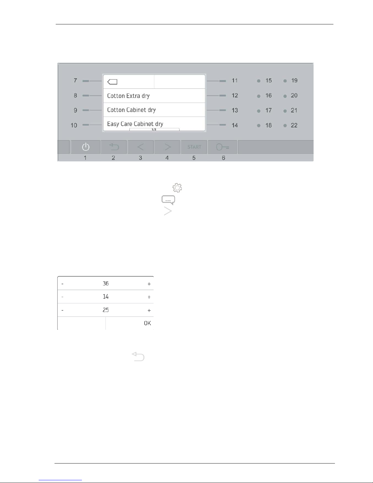
Setting of machine parameters
To star t theSettings menu, press the 11 button in the main menu.
(MFH: first of all hold down button 11 for 2 secs until the Settings menu appears)
By pressing down the arrow button 4 for a long time (5 seconds), you can access page 2 of
the settings menu.
Select Service Function and enter the service code 36-14-25 (01-02-03 field trial).
Important
This service code may only be handed over to authorised service organisations!
There is a separate code available for application technicians, facility managers and
administration, who would like to read out the operating data (see chapter Operating data).
The Machine Parameter menu appears. Select the individual machine parameters according to
the information in chapter Model overview and machine parameters.
Pressing the Back button (or after no mor e than 2 minutes after the last entry) exits t he
Settings menu.
When exiting the menu, changes must be confirmed with Yes or discarded with No.
2.1 Machine type
On setting the machine type, the control system is adjusted to suit the different machine sizes.
Nominal values for temperatures, moisture measurement, extra drying times of the individual
programmes. Time tables for the preview of the programme duration.

Dryer WT14 Service instructions
638 155 AL
page 4 / 34
11 / 2016
2.2 UI-Table (User Interface)
This setting allows the adjustment of the control system to the various models.
IMPORTANT: If you change the UI table and save these changes, the machine is automatically
reset to default settings.
2.3 Heating variant
Electric Settings for all domestic appliances.
Steam indirect This setting has no influence on any domestic appliances.
Hot water This setting has no influence on any domestic appliances.
2.4 Self-cleaning
Yes Solenoid installed for cleaning the evaporator.
No No Y-valve and no solenoid. Condensate is either pumped into the condensate
drawer or into the drainage hose.
2.5 Y-valve
Yes Y-valve installed. The condensate is either pumped up into the condensate
container (cleaning) or to the outside into the drainage hose.
No No Y-valve. Condensate is always pumped into the drainage hose.
2.6 Welcome text
Neutral Without welcome text and logo
Schulthess ... The selected company name always appears on the display on turning on the
machine.
2.7 Payment options
These functions are described in the CRM14 Payment System guide.
Without No payment system installed
Card CRM14 (Cash Reader Module) installed
Token Unit with integrated token function
Coin Unit with integrated coin function
RS-485 Module RS485 installed
2.8 Lock settings
Yes The settings are blocked for the customer, apart from the Language
(temporary), Time and Date settings (these are never blocked).
No The settings are available to the customer

Dryer WT14 Service instructions
638 155 AL
page 5 / 34
11 / 2016
2.9 Filter cleaning display
Off No display
5 programmes After the set number of programmes have run, the message "Clean filter C"
up to is displayed. The message disappears when the filter is removed.
25 programmes
2.10 Maintenance interval
No No instruction to maintain the machine will appear.
500 - 4000 After this number of programmes the notification "Machine maintenance due"
will be displayed. After a further 50 programmes the notification will be
displayed again, thereafter after every 10th programme, until the counter is
zeroed.
500 – 4000 After the course of the set number of programmes, the notification "Machine
mandatory maintenance due“ is displayed.
After a further 50 programmes no further programmes can be performed until
the counter is zeroed (the number of programmes that can still be carried out
will be shown at every programme start).
Zeroing the "Maintenance interval" counter:
Enter the service function.
Select Reset maintenance counter.
The programme counter is zeroed.
2.11 Powe r outage AutoStart
No The programme remains stopped after a power cut. The programme resumes
by pressing the start button.
Yes The programme continues automatically after a power cut.
This setting has no meaning in EFH machines. The programme always
continues to run automatically after a power failure.
3 Settings for the customer
The individual settings are described in chapter Settings of the respective operating instructions.
4 Test programmes
Test programmes are called up as described in chapter Machine parameters.
Select the Test programmes menu after entering the service code.
The chosen test programme starts automatically.

Dryer WT14 Service instructions
638 155 AL
page 6 / 34
11 / 2016
4.1 High-voltage test (for production)
For the high-voltage test, the drive motor is run for two minutes in the same direction. The fan is
also operated and after 30 seconds, the condensate pump will also start up. All other consumers
are switched off.
This test programme is terminated after two minutes.
4.2 Drying programme
During the duration of this programme, the display shows the temperatures of the temperature
sensors in the machine.
SFH HP
During the first 40 seconds the drum motor (including process air fan) and the compressor are in
operation. Then the sub cooler fan also switches on.
During minute 3 and 4 only the drum motor (including process air fan) is in operation.
SFH C
The machine runs a 4-minute heating cycle followed by a 2-minute cooling cycle.
The condensate is drained at the end.
AB HP
During the first 2 minutes the drum motor, the process air fan and the compressor are in
operation
The auxiliary heater turns on until the air temperature reaches 40 °C. Then the lower radiator fan
switches on, but with a 40 second delay.
During minute 3 and 4 only the drum motor and the process air fan are in operation.
4.3 Heating
SFH HP
During the first 30 seconds the drum motor (including process air fan) and the compressor are in
operation.
Let run for another 10 seconds, and then the drum motor (including process air fan) and the sub
cooler fan are in operation.
SFH C
The drive motor starts up. The high-power heater is activated first for 5 seconds, then the lowpower heater. The drive motor runs for about 30 seconds longer.
AB HP
The drum motor, the process air fan, the compressor, the low-power heater and the sub cooler
fan are activated sequentially. After 16 seconds this programme is terminated.
4.4 Condensate pump
SFH HP and AB HP
First the Y-valve is actuated. After 60 seconds, the condensate pump will start up and pump the
water to the outside. The pump runs for 60 seconds and then the programme ends.
SFH C
The condensate pump runs for 60 seconds.
4.5 Reversing
SFH
Inspection of the drive. The drum will rotate clockwise for 10 seconds, then it will stop for 2
seconds rotate again clockwise for 10 seconds, and so on.
The fan also runs. The programme ends after two minutes.

Dryer WT14 Service instructions
638 155 AL
page 7 / 34
11 / 2016
AB
Inspection of the drive. The drum will rotate clockwise for 10 seconds, then it will stop for 2
seconds, rotate counterclockwise for 10 seconds, stop for 2 seconds, etc.
4.6 Fan motor
SFH
The drum motor will be actuated for 2 minutes. The process air fan also runs on the axle of the
drum motor.
AB
The process air fan will be actuated for 2 minutes.
4.7 Moisture measurement
By applying a short circuit between the electrodes at the inside of the drum front, the moisture
measurement function can be tested.
- Open door and insert a door locking latch into the door lock.
- Start the moisture measurement test programme. The display shows an increasing value.
- Induce a short circuit. The value will decrease again.
- Remove the short circuit. The value will start to increase again.
After 2 minutes the test programme is exited.
4.8 Operating buttons
When operating a button, the corresponding touch value is shown in a green field. The test
programme is exited 10 seconds after the last push of a button.
4.9 Self-cleaning
SFH HP and AB HP
Pumping up in the condensate container, cleaning of the front heat exchanger (condensate dripoff) and pumping the condensate out of the device is tested.
First, 3.0 litres of water are added to the bottom assembly via the lint filter in the door opening,
where the water flows into the condensate pan after flowing through filter C (only MFH).
The condensate pump switches on, as soon as the condensate electrode is submerged in water.
After that, close the door and start test programme.
The water from the bottom assembly is pumped up within 90 seconds (the
condensate tank overflows after 1.9 litres and the excess water flows back into the bottom
assembly).
Next, the Y-valve is activated and stays open until the end of the programme.
After 60 seconds switchover time, the condensate pump starts and the rinse valve opens for 5
seconds (knocking noise at the solenoid).
The water flows downwards from the upper container through the front heat exchanger (heat
pump's vaporiser unit) and removes any pieces of fluff from the entire surface of the heat
exchanger.
The plinth panel with the filter C can be opened to observe the dripping
(only AB). The condensate is pumped out of the bottom assembly into the drainage hose within
90 seconds.
For the pump performance when pumping out, one measures the time required to pump back out
the 3 litres poured in at the beginning, i.e. the time interval between the knocking noise occurring
and the moment in time, when the condensate pump sucks in air and the water in the condensate
hose starts to swing back and forth.
(The allocated time is approx. 30 to 70 seconds, depending on the level of the condensate hose.)
Dryer WT14 Service instructions
638 155 AL
page 8 / 34
11 / 2016
5 Operating data
Using this function, the operating data stored in the control PCB are displayed.
5.1 Calling up the operating data
In the Settings menu, the Operating data menu can be called up on the second page. The
operating data code (28-39-17) must be entered for access.
This operating data code may be forwarded to interested persons. (Application technicians,
facility managers administrations)
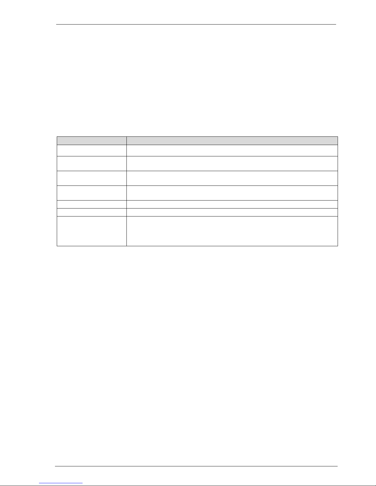
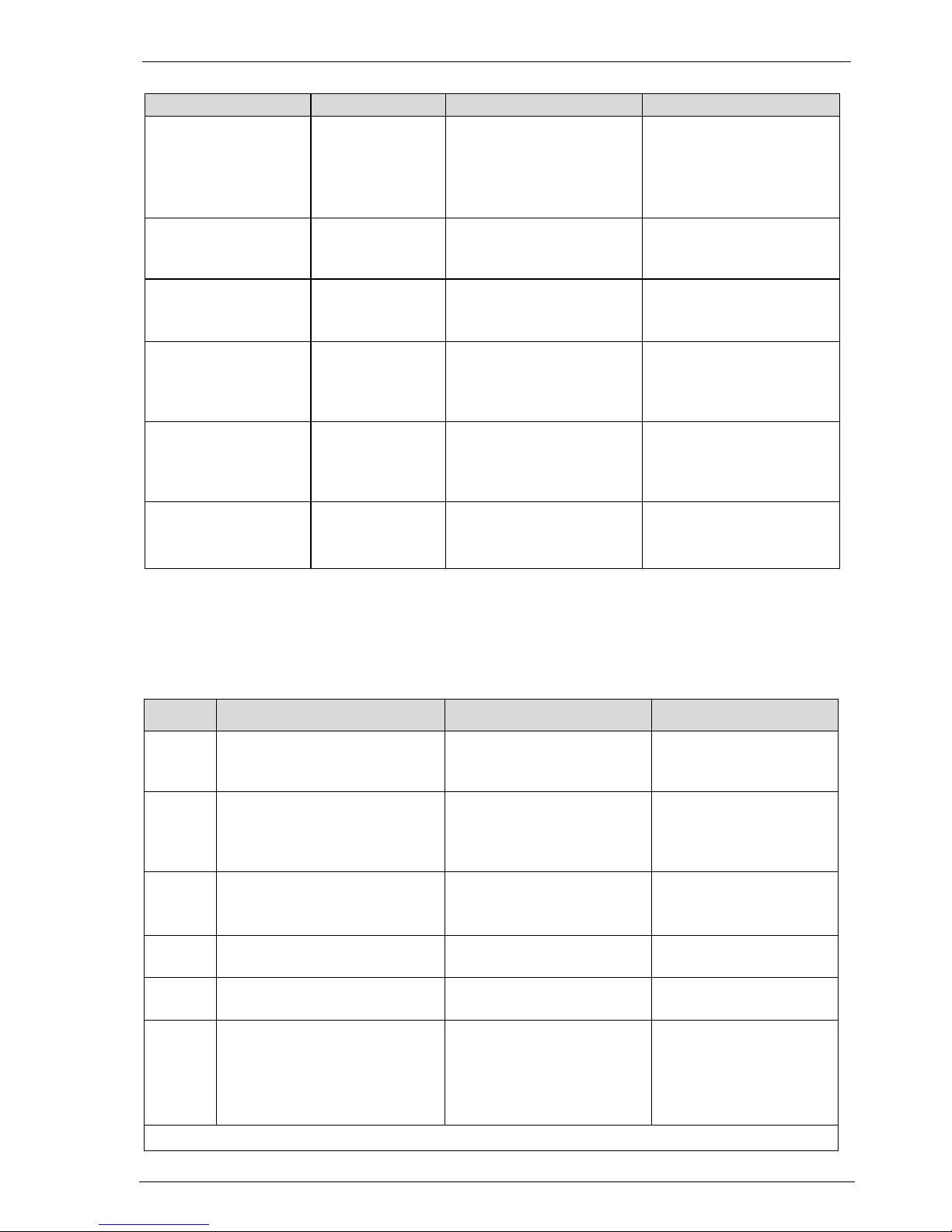
5.2 Operating data survey
Operating data
Information
Error messages
Display of the last 20 errors, with time and date stamp
Last drying
programmes
Display of the last 20 programmes runs, with programme number, programme
name, time and date stamp
Number of wash
programmes
Display of the number of completely run programmes (no stepping forward)
Operating hours Display of the current operating hours (loosening up resp. crease protection
are counted as well)
Software version
Display of the current firmware version
Machine number
Display of the machine number
Last service inspection
Display, when the machine was inspected last by a service technician
Format: XX.XX.XX / YY
X = Service visit date (DD.MM.YY)
Y = letters A - Z; service technician initials
Dryer WT14 Service instructions
638 155 AL
page 9 / 34
11 / 2016
6 Error messages
Two different types of error messages exist:
Error messages in the form of a plain text display
These errors can usually be corrected by the user.
Error messages F
These errors must be corrected by a service technician.
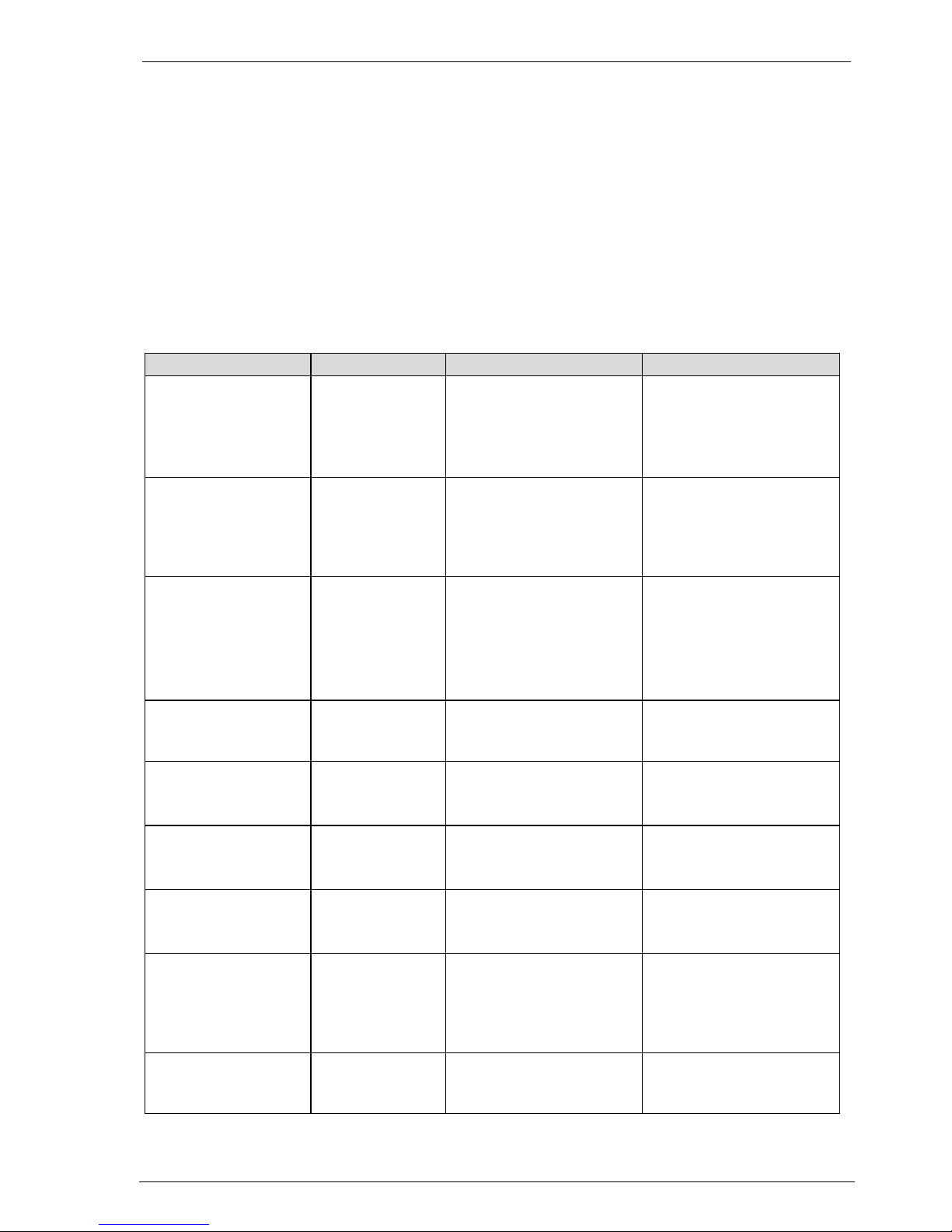
6.1 Plain text message
Depending on the type of error, different procedures are required to acknowledge the message.
Display Error type Cause Reaction
„Display is dark“ No power supply to
the control panel
Control panel defective or
interruption in the cable
between power board and
operator board.
The current programme
switches to cool down.
Child lock active
Child lock active Child look is activated in the
user parameters. For actions
like "Open door" or "Start
programme", always press
button "11" first.
Programme does not start.
Pop-up for 5 sec.
H-01
Check drain
Collected
condensate water
could not be
pumped out in last
12 minutes.
Condensate pump or Yvalve defect.
Level electrode is shortcircuited.
Hose plugged or hose
pinched.
The current programme
switches to cool down.
Then cancel or continue.
Insert filter «C»
then press start button
Filter "C" not
properly inserted at
startup
Filter is missing, or solenoid
switch is defective. (Filter
monitoring)
Once the error is eliminated,
the programme can be
started.
Insert filter «C»
Cancel / Continue
H-03
Filter "C" removed
during programme.
Filter or solenoid switch is
defective. (Filter monitoring)
Once the error is eliminated,
the programme can be
started.
Close door,
then press start button
The start button
was pressed with
the door open.
Door is open or door lock is
defective.
No programme can be
started.
Clean fluff filter
(displayed at the end of
the programme)
Timeout
Filter is plugged or heat
output is insufficient.
The module moisture
measurement took longer
than 150 minutes.
Clean fluff filter
(displayed during the
programme)
H-09
Timeout Filter is plugged, heat output
is insufficient, the process
fan does not run or the
moisture measurement unit
is defective.
The module moisture
measurement took longer
than 240 minutes.
Clean filter „C“
Filter cleaning is
due
The number configured in
the filter maintenance menu
has been reached
Filter "C" must be cleaned.
Dryer WT14 Service instructions
638 155 AL
page 10 / 34
11 / 2016
Display
Error type
Cause
Reaction
Error door lock
H-14
Door did not open
after repeated
pressing of the
door release button
The door lock is overheated,
defective or the control
signal to the door lock is
interrupted.
Door release is disabled for
30 sec. to cool down the coil.
Machine maintenance
due
The machine
needs to be
serviced
The number configured in
the machine maintenance
menu has been reached.
Drying can be continued.
The message is displayed
sporadically.
Machine maintenance
due
No. programmes still
The machine must
be serviced soon
The number configured in
the machine maintenance
menu has been reached.
Only a limited number of
programs can still be run.
Machine maintenance
due now
H-20
The machine must
now be serviced
The mandatory number
configured in the service
interval menu has been
reached.
Drying can only be continued
when the maintenance
counter has been reset in
the service menu.
Programme stopped
H-21
The On/Off button
was pressed
during a
programme.
The programme was
stopped.
The current programme
switches to cool down.
Default settings
H-23
Security prompt The user selected the
settings "Default settings".
The machine is reset to the
settings at the time of
delivery.
6.2 F-error messages
F-error messages are displayed as "Error F-XX, programme cancelled, inform customer
service". When the error message is acknowledged with "OK, the machine restarts.
If the error cause was not corrected, the error message appears again.
Display
Error type
Cause
Reaction
F-11 NTC1 sensor interruption for
measuring the supply air or hot
gas temperature, respectively
NTC probe interruption
The current programme
switches to cool down.
F-12 NTC1 sensor short-circuit for
measuring the supply air or hot
gas temperature, respectively.
NTC probe short
circuit
The current programme
switches to cool down.
F-15
NTC3 sensor interruption for
measuring exhaust temperature.
NTC probe interruption
The current programme
switches to cool down.
F-16
NTC3 sensor interruption for
measuring exhaust temperature.
NTC probe interruption
The current programme
switches to cool down.
F-19
Compressor contactor does not
open.
Contacts are stuck together. Compressor runs all the
time.
F-30 No connection to the power
board.
The cable between operating
and control part is
interrupted.
The control part does not
receive a response from the
power part
The current programme
stops.
All consumers are
switched off.within 30
seconds.
F-50 – F-53: See Service instructions „Payment system CRM14”

Dryer WT14 Service instructions
638 155 AL
page 11 / 34
11 / 2016
7 Replacement of control and power boards
7.1 Replacing a control board
When the control PCB starts up for the first time, the "high-voltage test" and the "drying
programme" test programme are automatically executed.
The test programmes can be terminated using "Cancel".
IMPORTANT:
Parameter visibility depends on the set UI table.
Compliance with the following sequence is imported during parametrisation after control PCB
replacement:
1. First configure the UI table in the machine parameters.
2. Exit the menu via the Back button and save the changes.
3. Configure the machine type in the machine parameters.
4. Configure the remaining parameters acc. to the machine type, acc. to the table Model
overview and machine parameters (ex factory settings)
5. IMPORTANT:
Changes to the machine parameters must be saved on the control PCB using the service
function Save default settings.
REASON:
If the customer resets his settings to Default settings, the settings saved on the control PCB
AND the machine parameters are called up again.
Error message when starting the machine
If the configuration of the new control PCB does not match the machine,
an error message is shown on the display during control PCB start-up.
Press and hold the arrow key 4 , until the input menu appears for the service code.
This way, the machine parameter menu can be accessed despite the error message.
CRM14
Except for the registration number, all parameters will be set to default and must be re-configured.
7.2 Replacing a power board
No special settings must be applied.
 Loading...