

Page 1

TeSys DFB Library V2 for Unity Pro
1672609EN-03 01/2020
TeSys DFB Library V2 for Unity
Pro
a SoCollaborative library
User Manual
01/2020
1672609EN-03
www.se.com
Page 2

The information provided in this documentation contains general descriptions and/or technical characteristics of the performance of the products contained herein. This documentation is not intended as a
substitute for and is not to be used for determining suitability or reliability of these products for specific user
applications. It is the duty of any such user or integrator to perform the appropriate and complete risk
analysis, evaluation and testing of the products with respect to the relevant specific application or use
thereof. Neither Schneider Electric nor any of its affiliates or subsidiaries shall be responsible or liable for
misuse of the information contained herein. If you have any suggestions for improvements or amendments
or have found errors in this publication, please notify us.
You agree not to reproduce, other than for your own personal, noncommercial use, all or part of this
document on any medium whatsoever without permission of Schneider Electric, given in writing. You also
agree not to establish any hypertext links to this document or its content. Schneider Electric does not grant
any right or license for the personal and noncommercial use of the document or its content, except for a
non-exclusive license to consult it on an "as is" basis, at your own risk. All other rights are reserved.
All pertinent state, regional, and local safety regulations must be observed when installing and using this
product. For reasons of safety and to help ensure compliance with documented system data, only the
manufacturer should perform repairs to components.
When devices are used for applications with technical safety requirements, the relevant instructions must
be followed.
Failure to use Schneider Electric software or approved software with our hardware products may result in
injury, harm, or improper operating results.
Failure to observe this information can result in injury or equipment damage.
© 2020 Schneider Electric. All rights reserved.
2 1672609EN-03 01/2020
Page 3

Table of Contents
Safety Information. . . . . . . . . . . . . . . . . . . . . . . . . . . . . . . . . . . . . . . . . . . . 5
About the Book . . . . . . . . . . . . . . . . . . . . . . . . . . . . . . . . . . . . . . . . . . . . . . 9
Chapter 1 Introduction. . . . . . . . . . . . . . . . . . . . . . . . . . . . . . . . . . . . . . . . . . . . . . . . . 11
Presentation . . . . . . . . . . . . . . . . . . . . . . . . . . . . . . . . . . . . . . . . . . . . . . . . . . . . . . . . . . . . .
TeSys DFB Library Overview . . . . . . . . . . . . . . . . . . . . . . . . . . . . . . . . . . . . . . . . . . . . . . . .
TeSys DFB Sequencing . . . . . . . . . . . . . . . . . . . . . . . . . . . . . . . . . . . . . . . . . . . . . . . . . . . .
Chapter 2 Modbus SL DFB . . . . . . . . . . . . . . . . . . . . . . . . . . . . . . . . . . . . . . . . . . . . . 21
Ctrl_cmd_mdb_u_••••: TeSys U Control/Command for Modbus SL. . . . . . . . . . . . . . . . . . . .
Comm_manager_u: TeSys U Communication Management for Modbus SL . . . . . . . . . . . .
Ctrl_cmd_mdb_t_••••: TeSys T Control/Command for Modbus SL . . . . . . . . . . . . . . . . . . . .
Comm_manager_t: TeSys T Communication Management for Modbus SL . . . . . . . . . . . . .
Chapter 3 Modbus SL and Modbus/TCP DFB . . . . . . . . . . . . . . . . . . . . . . . . . . . . . . 39
Special_mdb_u_••••: TeSys U DFB for Modbus SL and Modbus/TCP . . . . . . . . . . . . . . . . .
Special_mdb_t_••••: TeSys T DFB for Modbus SL and Modbus/TCP . . . . . . . . . . . . . . . . . .
Custom_mdb_••••: Custom Read DFB for Modbus SL and Modbus/TCP . . . . . . . . . . . . . . .
Chapter 4 Modbus/TCP DFB for Quantum PLC . . . . . . . . . . . . . . . . . . . . . . . . . . . . . 61
Special_mdb_u_addq: TeSys U DFB for Modbus/TCP for Quantum PLC . . . . . . . . . . . . . .
Special_mdb_t_addq: TeSys T DFB for Modbus/TCP for Quantum PLC . . . . . . . . . . . . . . .
Custom_mdb_addq: Custom Read DFB for Modbus/TCP for Quantum PLC . . . . . . . . . . . .
Chapter 5 Profibus DFB . . . . . . . . . . . . . . . . . . . . . . . . . . . . . . . . . . . . . . . . . . . . . . . 81
Ctrl_pfb_u_ms: TeSys U Control/Command for Profibus DP MS . . . . . . . . . . . . . . . . . . . . .
Ctrl_pfb_u_mms: TeSys U Control/Command for Profibus DP MMS . . . . . . . . . . . . . . . . . .
Ctrl_pfb_t_mms: TeSys T Control/Command for Profibus DP MMS . . . . . . . . . . . . . . . . . . .
Chapter 6 Cyclic Control/Command DFB . . . . . . . . . . . . . . . . . . . . . . . . . . . . . . . . . . 89
Ctrl_cmd_u: TeSys U Cyclic Control/Command . . . . . . . . . . . . . . . . . . . . . . . . . . . . . . . . . .
Ctrl_cmd_t: TeSys T Cyclic Control/Command . . . . . . . . . . . . . . . . . . . . . . . . . . . . . . . . . . .
Chapter 7 PKW Exchanges DFB. . . . . . . . . . . . . . . . . . . . . . . . . . . . . . . . . . . . . . . . . 95
Special_pkw_u: TeSys U DFB for PKW Exchanges . . . . . . . . . . . . . . . . . . . . . . . . . . . . . . .
Special_pkw_t: TeSys T DFB for PKW Exchanges. . . . . . . . . . . . . . . . . . . . . . . . . . . . . . . .
Custom_pkw: Custom Read DFB for PKW Exchanges. . . . . . . . . . . . . . . . . . . . . . . . . . . . .
Chapter 8 Treatment DFB . . . . . . . . . . . . . . . . . . . . . . . . . . . . . . . . . . . . . . . . . . . . . . 117
Scale: TeSys U DFB for Measurement Unit Conversion. . . . . . . . . . . . . . . . . . . . . . . . . . . .
Timestamp_•: TeSys U DFB for Data Time-Stamping. . . . . . . . . . . . . . . . . . . . . . . . . . . . . .
12
13
17
22
26
30
34
40
46
58
62
68
78
82
84
86
90
92
96
102
113
118
120
1672609EN-03 01/2020 3
Page 4

4 1672609EN-03 01/2020
Page 5
Safety Information
Important Information
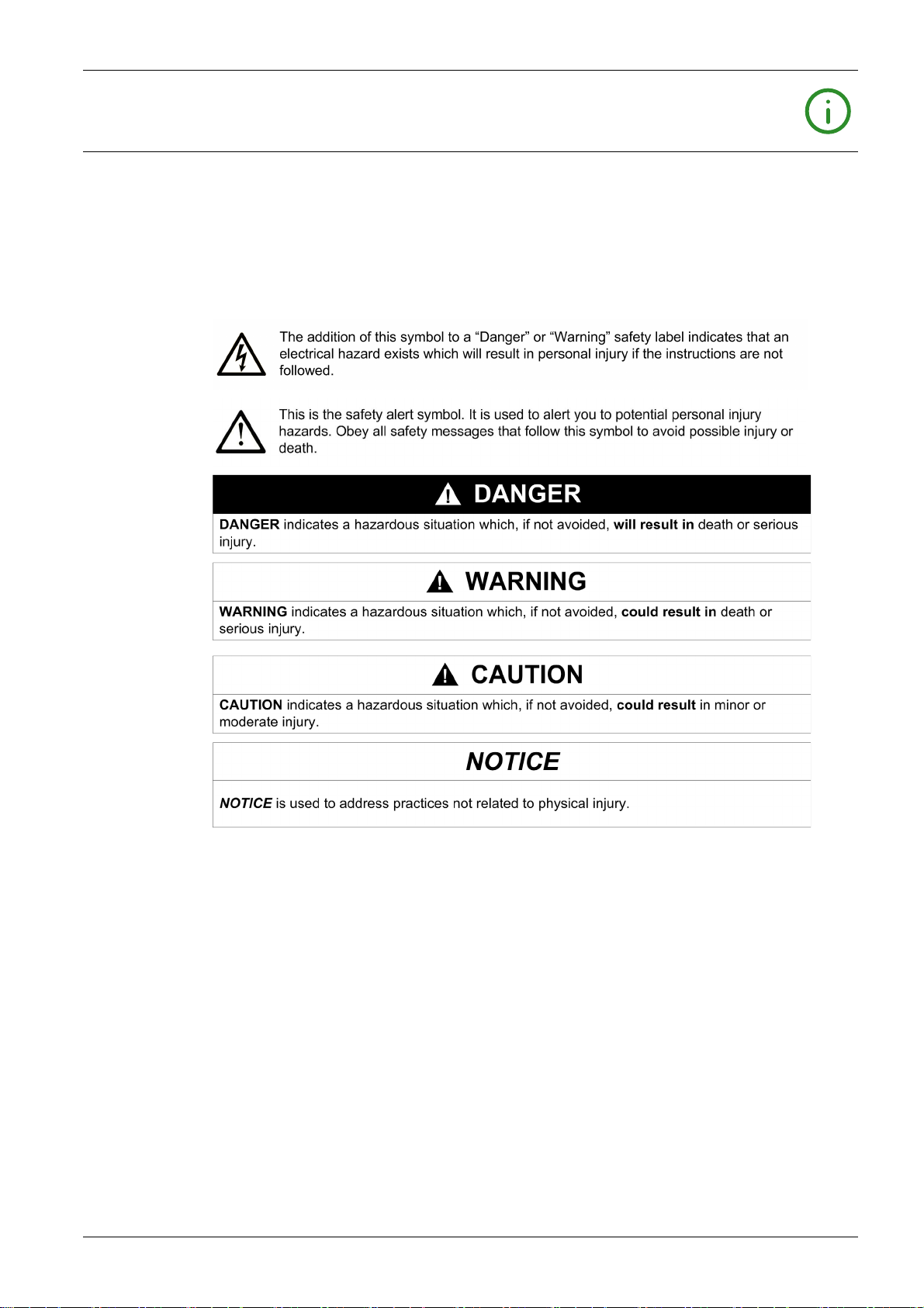
NOTICE
Read these instructions carefully, and look at the equipment to become familiar with the device before
trying to install, operate, service, or maintain it. The following special messages may appear throughout
this documentation or on the equipment to warn of potential hazards or to call attention to information that
clarifies or simplifies a procedure.
PLEASE NOTE
Electrical equipment should be installed, operated, serviced, and maintained only by qualified personnel.
No responsibility is assumed by Schneider Electric for any consequences arising out of the use of this
material.
A qualified person is one who has skills and knowledge related to the construction and operation of
electrical equipment and its installation, and has received safety training to recognize and avoid the
hazards involved.
BEFORE YOU BEGIN
Do not use this product on machinery lacking effective point-of-operation guarding. Lack of effective pointof-operation guarding on a machine can result in serious injury to the operator of that machine.
1672609EN-03 01/2020 5
Page 6
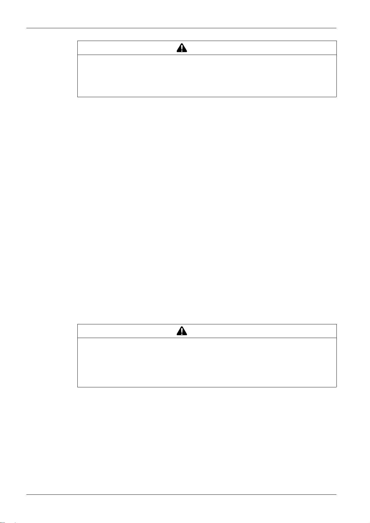
WARNING
UNGUARDED EQUIPMENT
Do not use this software and related automation equipment on equipment which does not have point-
of-operation protection.
Do not reach into machinery during operation.
Failure to follow these instructions can result in death, serious injury, or equipment damage.
This automation equipment and related software is used to control a variety of industrial processes. The
type or model of automation equipment suitable for each application will vary depending on factors such
as the control function required, degree of protection required, production methods, unusual conditions,
government regulations, etc. In some applications, more than one processor may be required, as when
backup redundancy is needed.
Only you, the user, machine builder or system integrator can be aware of all the conditions and factors
present during setup, operation, and maintenance of the machine and, therefore, can determine the
automation equipment and the related safeties and interlocks which can be properly used. When selecting
automation and control equipment and related software for a particular application, you should refer to the
applicable local and national standards and regulations. The National Safety Council's Accident Prevention
Manual (nationally recognized in the United States of America) also provides much useful information.
In some applications, such as packaging machinery, additional operator protection such as point-ofoperation guarding must be provided. This is necessary if the operator's hands and other parts of the body
are free to enter the pinch points or other hazardous areas and serious injury can occur. Software products
alone cannot protect an operator from injury. For this reason the software cannot be substituted for or take
the place of point-of-operation protection.
Ensure that appropriate safeties and mechanical/electrical interlocks related to point-of-operation
protection have been installed and are operational before placing the equipment into service. All interlocks
and safeties related to point-of-operation protection must be coordinated with the related automation
equipment and software programming.
NOTE: Coordination of safeties and mechanical/electrical interlocks for point-of-operation protection is
outside the scope of the Function Block Library, System User Guide, or other implementation referenced
in this documentation.
START-UP AND TEST
Before using electrical control and automation equipment for regular operation after installation, the system
should be given a start-up test by qualified personnel to verify correct operation of the equipment. It is
important that arrangements for such a check be made and that enough time is allowed to perform
complete and satisfactory testing.
Follow all start-up tests recommended in the equipment documentation. Store all equipment
documentation for future references.
Software testing must be done in both simulated and real environments.
Verify that the completed system is free from all short circuits and temporary grounds that are not installed
according to local regulations (according to the National Electrical Code in the U.S.A, for instance). If highpotential voltage testing is necessary, follow recommendations in equipment documentation to prevent
accidental equipment damage.
Before energizing equipment:
Remove tools, meters, and debris from equipment.
Close the equipment enclosure door.
WARNING
EQUIPMENT OPERATION HAZARD
Verify that all installation and set up procedures have been completed.
Before operational tests are performed, remove all blocks or other temporary holding means used for
shipment from all component devices.
Remove tools, meters, and debris from equipment.
Failure to follow these instructions can result in death, serious injury, or equipment damage.
6 1672609EN-03 01/2020
Page 7

Remove all temporary grounds from incoming power lines.
Perform all start-up tests recommended by the manufacturer.
OPERATION AND ADJUSTMENTS
The following precautions are from the NEMA Standards Publication ICS 7.1-1995 (English version
prevails):
Regardless of the care exercised in the design and manufacture of equipment or in the selection and
ratings of components, there are hazards that can be encountered if such equipment is improperly
operated.
It is sometimes possible to misadjust the equipment and thus produce unsatisfactory or unsafe
operation. Always use the manufacturer’s instructions as a guide for functional adjustments. Personnel
who have access to these adjustments should be familiar with the equipment manufacturer’s
instructions and the machinery used with the electrical equipment.
Only those operational adjustments actually required by the operator should be accessible to the
operator. Access to other controls should be restricted to prevent unauthorized changes in operating
characteristics.
1672609EN-03 01/2020 7
Page 8

8 1672609EN-03 01/2020
Page 9

At a Glance
Document Scope
Validity Note
About the Book
This manual describes the DFB (Derived Function Block) library dedicated to TeSys U starter-controllers
and TeSys T motor management systems.
It is intended for design engineers and system integrators who have a good knowledge of Unity Pro PLC
programming platforms.
The purposes of this manual are to
describe the scope of the DFB library and platform compatibility,
describe the DFB characteristics and the download procedure from the Schneider Electric website,
explain how to implement the DFB in the PLC application.
This TeSys library is compatible and usable with the following versions of Unity Pro:
Unity Pro V2.3 SP2
Unity Pro V3.0
Unity Pro V3.1
Unity Pro V4.0 or later
This manual is valid for all TeSys DFBs. The following table describes the differences between versions 1
and 2 of Unity Pro:
Library Version Date Evolution
V1 03/2009 Initial version
V2 09/2009 Addition of 3 new DFBs for Quantum PLC:
Special_mdb_u_addq
Special_mdb_t_addq
Custom_mdb_addq
Evolution of 2 existing DFBs to be compatible with Quantum PLC:
Ctrl_cmd_u
Ctrl_cmd_t
Related Documents
Title of Documentation Reference Number
TeSys U LUCM and LUCMT Multifunction Control Unit User Manual 1743237
TeSys U Communication Variables User Manual 1744082
TeSys U LULC032-033 Modbus Communication Module User M
anual
TeSys U LULC15 Advantys STB Communication Module User
Manual
TeSys U LULC08 CANopen Communication Module User Manual 1744084
TeSys U LULC07 Profibus DP Communication Module User Manual 1672610
TeSys T LTMR Motor Management Controller - User Guide DOCA0127
TeSys T LTMR Ethernet Communication Guide DOCA0129
TeSys T LTMR Modbus Communication Guide DOCA0130
TeSys T LTMR PROFIBUS DP Communication Guide DOCA0131
TeSys T LTMR CANopen Communication Guide DOCA0132
LAD9AP3•• Quickfit Instruction Sheet 1568984
LUFC00 Parallel Wiring Module Instruction Sheet 1743239
LU9G02 Splitter Box Instruction Sheet 1638822
LU9G03 Splitter Box Instruction Sheet AAV90641
1743234
1744083
1672609EN-03 01/2020 9
Page 10

You can download these technical publications and other technical information from our website at
https://www.se.com/ww/en/download/ .
10 1672609EN-03 01/2020
Page 11

TeSys DFB Library V2 for Unity Pro
Introduction
1672609EN-03 01/2020
Introduction
Chapter 1
Introduction
Introduction
This chapter gives an overview of the TeSys U and TeSys T DFB (Derived Function Block) library,
presents the DFB library download procedure from the Schneider Electric website, and describes the
sequencing system used to synchronize the treatment between DFBs.
What Is in This Chapter?
This chapter contains the following topics:
Presentation 12
TeSys DFB Library Overview 13
TeSys DFB Sequencing 17
Topic Page
1672609EN-03 01/2020 11
Page 12

Introduction
Presentation
Aim of the TeSys DFB Library
The TeSys DFB library has been developed to simplify and optimize the integration of TeSys U startercontrollers and TeSys T motor management systems in PLC applications, for both PLC programmers and
end users.
The TeSys DFB library for Unity Pro can be ordered with part number UNYLTSZFUWB.
Advantages for the PLC Programmer
The TeSys DFB library enables the PLC programmer to
simplify the program design: the program is split by functions (control, command, data treatment,...),
optimize the programming time: the DFB is tested and can be re-used for different applications,
increase the program understanding: the applications are coded in the same way using the common
DFB,
optimize the program size: the same code is used for each DFB instantiation,
simplify the TeSys U and TeSys T integration: the data mapping management is masked.
Advantages for the End User
The TeSys DFB library enables the end user to
optimize the communication response time:
the Modbus requests management is optimized,
the data exchange management is optimized,
the product performance is taken into account,
have a functional view of the motor-starter by providing direct access to common functions (Ready,
Alarm, Run, Stop,...),
group data related to a specific application (diagnostic, maintenance, measurement,...) through a
program number,
facilitate debugging: variables used by the DFB are identified on its interface.
PLC Platform Compatibility
The TeSys DFB library can be integrated in the Unity Pro programming platform with Quantum, Premium
and M340 PLC platforms.
TeSys Compatibility
The TeSys DFB library for Unity Pro is compatible with:
TeSys U starter-controllers (up to 38 A/18.5 kW or 25 hp),
TeSys T motor management system.
Communication Protocol Compatibility
The following table describes the TeSys DFB library compatibility with communication protocols and the
corresponding TeSys U and TeSys T assemblies.
Protocol TeSys U TeSys T
Modbus SL
(Serial Line)
Modbus/TCP Starter-controller with LULC033 Modbus
Profibus DP Starter-controller with LULC07 Profibus DP
CANopen Starter-controller with LULC08 CANopen
Advantys STB with
communication module
Starter-controller with LULC033 Modbus
communication module
communication module and Ethernet gateway
(TeSysPort, TSXETG100, TSXETG1000,...)
communication module
communication module
Starter-controller with LULC15 Advantys STB
communication module
LTMR••M•• Modbus SL controller with or without the
LTM E expansion module
LTMR••E•• Modbus/TCP controller with or without the
LTM E expansion module
LTMR••P•• Profibus DP controller with or without the
LTM E expansion module
LTMR••C•• CANopen controller with or without the
LTM E expansion module
–
12
1672609EN-03 01/2020
Page 13

TeSys DFB Library Overview
TeSys DFB Library Organization
The following table lists the TeSys DFB library according to the communication protocol and service and
their availability according to the TeSys model:
Introduction
Communication Protocol /
Service
Modbus SL Ctrl_cmd_mdb_u_•••• √ √ –
Modbus SL and Modbus/TCP Custom_mdb_•••• √ – √
Modbus/TCP (for Quantum PLC) Custom_mdb_addq √ – √
Profibus DP Ctrl_pfb_u_ms √ √ –
Cyclic control/command
(Modbus/TCP (IO scanning),
CANopen, and Advantys STB)
PKW Special_pkw_u √ – –
Treatment Timestamp_• √ – –
DFB Name TeSys U up to
32 A
Comm_manager_u √ √ –
Ctrl_cmd_mdb_t_•••• – – √
Comm_manager_t – – √
Special_mdb_u_•••• √ – –
Special_mdb_t_•••• – – √
Special_mdb_u_addq √ – –
Special_mdb_t_addq – – √
Ctrl_pfb_u_mms √ – –
Ctrl_pfb_t_mms – – √
Ctrl_cmd_u (Modbus/TCP (IO scanning), CANopen, and
Advantys STB)
Ctrl_cmd_t (Modbus/TCP (IO scanning) and CANopen) – – √
Special_pkw_t – – √
Custom_pkw √ – √
Scale √ – –
√√–
TeSys U up to
38 A
TeSys T
Modbus SL DFB Library
The following table describes the Modbus SL (Serial Line) DFB library:
DFB Description For More Information
Ctrl_cmd_mdb_u_addr
Ctrl_cmd_mdb_u_addm
Comm_manager_u This DFB is dedicated to the control and command of up to 31 TeSys U
These DFBs are dedicated to the control and command of a single TeS ys
U starter-controller with any control unit and a LULC033 Modbus
communication module.
Ctrl_cmd_mdb_u_addr is dedicated to Premium PLC.
Ctrl_cmd_mdb_u_addm is dedicated to M340 PLC.
These DFBs enable the user to
read status register 455,
write command register 704,
reset communication loss (register 703, bit 3).
The program number enables the user to select bit or word control.
starter-controllers with any control unit and a LULC033 Modbus
communication module.
It must be associated with the Ctrl_cmd_mdb_u_•••• DFBs to manage the
Modbus requests sequencing.
It enables the user to
optimize the response time by taking into account the response time
of the devices,
send write requests only when necessary,
manage the disconnection and reconnection of a TeSys U Modbus
slave.
The program number enables the user to select different Modbus request
sequences.
Ctrl_cmd_mdb_u_••••: TeSys U
Control/Command for Modbus
SL, page 22
Comm_manager_u: TeSys U
Communication Management for
Modbus SL, page 26
1672609EN-03 01/2020 13
Page 14

Introduction
DFB Description For More Information
Ctrl_cmd_mdb_t_addr
Ctrl_cmd_mdb_t_addm
These DFBs are dedicated to the control and command of a single TeSys
T LTMR••M•• Modbus SL controller with or without the LTM E expansion
module.
Ctrl_cmd_mdb_t_addr is dedicated to Premium PLC.
Ctrl_cmd_mdb_t_addm is dedicated to M340 PLC.
Ctrl_cmd_mdb_t_••••: TeSys T
Control/Command for Modbus
SL, page 30
These DFBs enable the user to
read status registers 455 and 456,
write command register 704.
The program number enables the user to select bit or word control.
Comm_manager_t This DFB is dedicated to the control and command of several TeSys T
LTMR••M•• Modbus SL controllers with or without the LTM E expansion
module. It must be associated with the Ctrl_cmd_mdb_t_•••• DFBs to
Comm_manager_t: TeSys T
Communication Management for
Modbus SL, page 34
manage the Modbus requests sequencing.
It enables the user to
optimize the response time by taking into account the response time
of the devices,
send write requests only when necessary,
manage the disconnection and reconnection of a TeSys U Modbus
slave.
The program number enables the user to select different Modbus
requests sequences.
Modbus SL and Modbus/TCP Library
The following table describes the Modbus SL and Modbus/TCP library:
DFB Description For More Information
Special_mdb_u_addr
Special_mdb_u_addm
Special_mdb_t_addr
Special_mdb_t_addm
Custom_mdb_addr
Custom_mdb_addm
These DFBs are dedicated to the reading of up to 16 predefined registers
(diagnostic, maintenance, measurement,...) of a TeSys U starter-controller
(up to 32 A/15 kW or 20 hp) with a LUCM multifunction control unit and a
LULC033 Modbus communication module.
The program number enables the user to select the predefined registers.
Special_mdb_u_addr is dedicated to Premium PLC and can be used with
a TeSys U starter-controller connected on Modbus Serial Line or through
a Modbus/TCP gateway.
Special_mdb_u_addm is dedicated to M340 PLC and can be used with
a TeSys U starter-controller connected on Modbus Serial Line or through
a Modbus/TCP gateway.
These DFBs are dedicated to the reading of up to 16 predefined registers
(diagnostic, maintenance, measurement,...) of a TeSys T Modbus SL
controller or TeSys T Modbus/TCP controller with or without the LTM E
expansion module.
The program number enables the user to select the predefined registers.
Special_mdb_t_addr is dedicated to Premium PLC and can be used with
a TeSys T controller LTMR••M•• connected through Modbus Serial Line
or a TeSys T controller LTMR••E•• through a Modbus/TCP network.
Special_mdb_t_addm is dedicated to M340 PLC and can be used with a
TeSys T controller LTMR••M•• connected through Modbus Serial Line or
a TeSys T controller LTMR••E•• through a Modbus/TCP network.
These DFBs are dedicated to the reading of up to 5 sets of registers in one
single TeSys device.
A set of registers is defined by the address of the first register to read and
the length of the set (up to 16 registers per set).
Custom_mdb_addr is dedicated to Premium PLC and can be used with
a TeSys connected through Modbus Serial Line or through a
Modbus/TCP network.
Custom_mdb_addm is dedicated to M340 PLC and can be used with a
TeSys connected through Modbus Serial Line or through a Modbus/TCP
network.
Special_mdb_u_••••: TeSys U
DFB for Modbus SL and
Modbus/TCP, page 40
Special_mdb_t_••••: TeSys T
DFB for Modbus SL and
Modbus/TCP, page 46
Custom_mdb_••••: Custom Read
DFB for Modbus SL and
Modbus/TCP, page 58
14
1672609EN-03 01/2020
Page 15

Modbus/TCP Quantum Library
The following table describes the Modbus/TCP DFB library dedicated to Quantum PLC:
DFB Description For More Information
Special_mdb_u_addq This DFB is dedicated to the reading of up to 16 predefined registers
(diagnostic, maintenance, measurement,...) in a TeSys U starter-controller
(up to 32 A/15 kW or 20 hp) with a LUCM multifunction control unit and a
LULC033 Modbus communication module through a Modbus/TCP gateway
connected to a Quantum PLC.
The program number enables the user to select the predefined registers.
Special_mdb_t_addq This DFB is dedicated to the reading of up to 16 predefined registers
(diagnostic, maintenance, measurement,...) in a TeSys T Modbus/TCP
LTMR••E•• controller with or without the LTM E expansion module
connected to a Quantum PLC.
The program number enables the user to select the predefined registers.
Custom_mdb_addq This DFB is dedicated to the reading of up to 5 sets of registers in one single
TeSys device connected through Modbus/TCP to a Quantum PLC.
A set of registers is defined by the address of the first register to read and
the length of the set (up to 16 registers per set).
Special_mdb_u_addq: TeSys U
DFB for Modbus/TCP for
Quantum PLC, page 62
Special_mdb_t_addq: TeSys T
DFB for Modbus/TCP for
Quantum PLC, page 68
Custom_mdb_addq: Custom
Read DFB for Modbus/TCP for
Quantum PLC, page 78
Profibus DP DFB Library
The following table describes the Profibus DP DFB library:
DFB Description For More Information
Ctrl_pfb_u_ms This DFB is dedicated to the control and command of a single TeSys U
starter-controller with any control unit and a LULC07 Profibus DP
communication module using the Motor Starter profile.
Ctrl_pfb_u_mms This DFB is dedicated to the control and command of a single TeSys U
starter-controller (up to 32 A/15 kW or 20 hp) with a LUCM multifunction
control unit and a LULC07 Profibus DP communication module using the
Motor Management Starter profile.
Ctrl_pfb_t_ms This DFB is dedicated to the control and command of a single TeSys T
LTMR••P•• Profibus controller with or without the LTM E expansion module.
Ctrl_pfb_u_ms: TeSys U
Control/Command for Profibus DP
MS, page 82
Ctrl_pfb_u_mms: TeSys U
Control/Command for Profibus DP
MMS, page 84
Ctrl_pfb_t_mms: TeSys T
Control/Command for Profibus DP
MMS, page 86
Introduction
Cyclic Control/Command DFB Library
The following table describes the cyclic control/command (Modbus/TCP (IO scanning), CANopen, and
Advantys STB) DFB library:
DFB Description For More Information
Ctrl_cmd_u This DFB is dedicated to the control and command of a single TeSys U
starter-controller with any control unit and a LULC08 CANopen, a LULC15
STB communication module, or a LULC033 Modbus communication
module with an Ethernet gateway.
Ctrl_cmd_t This DFB is dedicated to the control and command of a single TeSys T
LTMR••C•• CANopen controller or a TeSys T LTMR••E•• Modbus/TCP
controller, with or without the LTM E expansion module.
Ctrl_cmd_u: TeSys U Cyclic
Control/Command, page 90
Ctrl_cmd_t: TeSys T Cyclic
Control/Command, page 92
1672609EN-03 01/2020 15
Page 16

Introduction
PKW DFB Library
The following table describes the PKW DFB library:
DFB Description For More Information
Special_pkw_u This DFB is dedicated to the reading of up to 16 predefined registers
(diagnostic, maintenance, measurement,...) of a single TeSys U startercontroller (up to 32 A/15 kW or 20 hp) with a LUCM multifunction control
unit and one of the following communication modules that support PKW
exchanges:
LULC07 (Profibus DP)
LULC08 (CANopen)
LULC15 (Advantys STB)
The program number enables the user to select the predefined registers.
Special_pkw_t This DFB is dedicated to the reading of up to 16 predefined registers
(diagnostic, maintenance, measurement,...) of a single TeSys T LTMR••P••
Profibus controller or a LTMR••C•• CANopen controller with or without the
LTM E expansion module.
The program number enables the user to select the predefined registers.
Custom_pkw This DFB is dedicated to the reading of up to 5 sets of registers of a single
TeSys device supporting PKW exchanges.
A set of registers is defined by the address of the first register to read and
the length of the set (up to 16 registers per set).
Special_pkw_u: TeSys U DFB for
PKW Exchanges, page 96
Special_pkw_t: TeSys T DFB for
PKW Exchanges, page 102
Custom_pkw: Custom Read DFB
for PKW Exchanges, page 113
Treatment DFB Library
The following table describes the treatment DFB library:
DFB Description For More Information
Scale This DFB is dedicated to the conversion of current measurement unit from
Timestamp
Timestamp_q
relative value (% FLA) to Amps for a TeSys U starter-controller (up to
32 A/15 kW or 20 hp) with a LUCM multifunction control unit. It also enables
the user to select another unit in the A...mA range.
These DFBs are dedicated to the time-stamping of up to 8 input registers of
a TeSys U starter-controller (up to 32 A/15 kW or 20 hp) with a LUCM
multifunction control unit. It provides an output table of the 8 time-stamped
registers and 4 date and time registers.
Timestamp is dedicated to Premium and M340 PLCs
Timestamp_q is dedicated to Quantum PLC.
Scale: TeSys U DFB for
Measurement Unit Conversion,
page 118
Timestamp_•: TeSys U DFB for
Data Time-Stamping, page 120
16
1672609EN-03 01/2020
Page 17
TeSys DFB Sequencing
Introduction
Some of the TeSys DFBs use a sequencing system using dedicated inputs and outputs that enable the
sequencing and the synchronization of the treatment between DFBs.
The following derived function blocks use a sequencing system:
Ctrl_cmd_mdb_u_••••
Ctrl_cmd_mdb_t_••••
Special_mdb_u_••••
Special_mdb_t_••••
Custom_mdb_••••
Special_pkw_u
Special_pkw_t
Custom_pkw
Timestamp_•
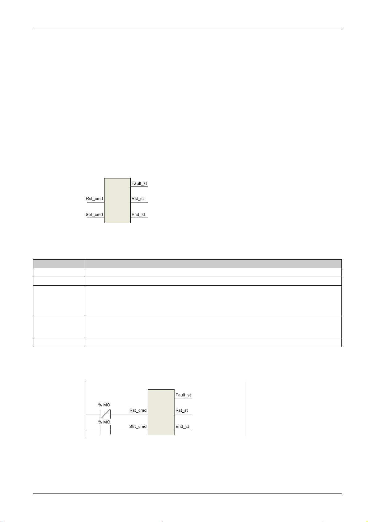
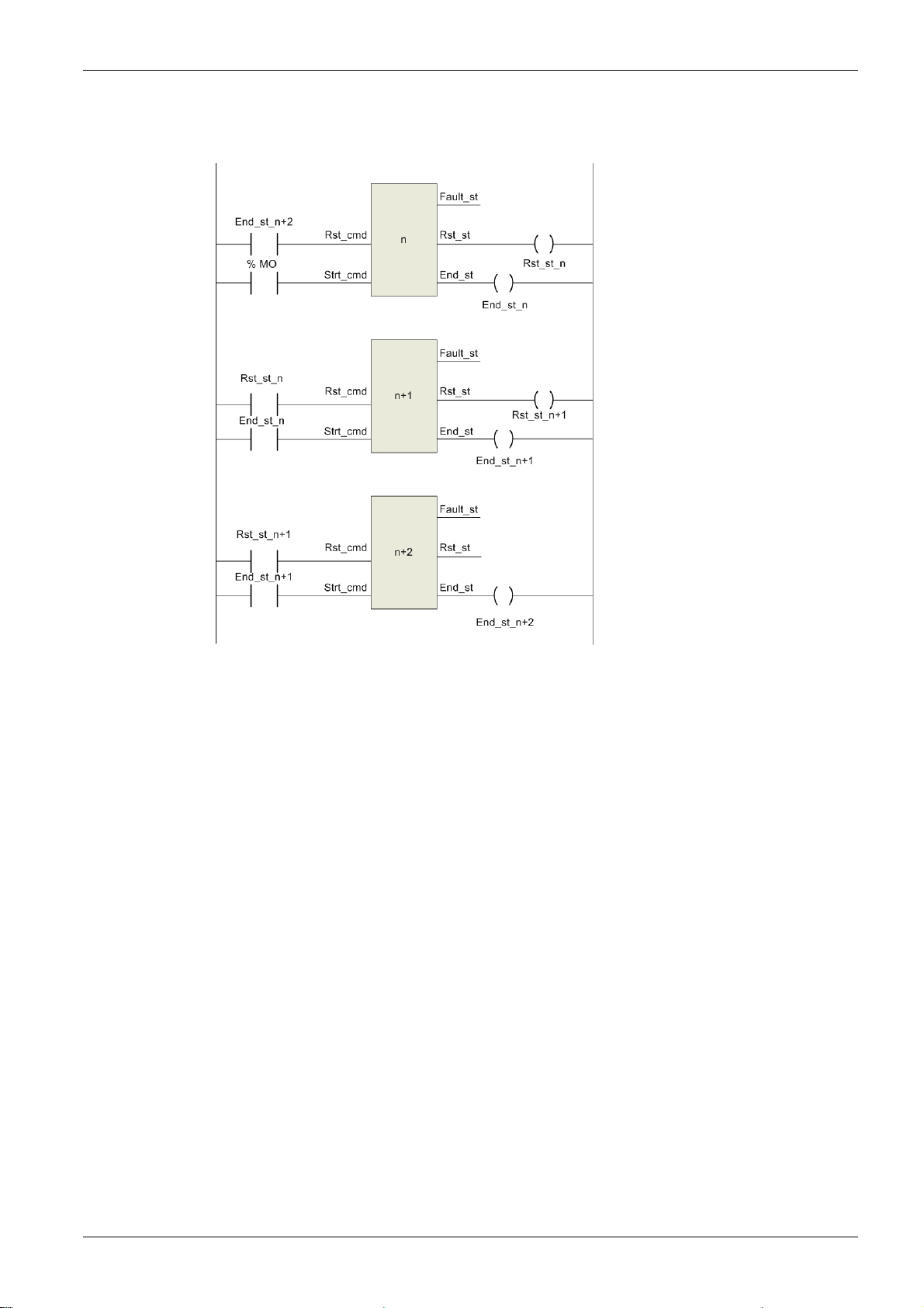
Sequencing System Principle
The sequencer has 2 boolean inputs and 3 boolean outputs:
Introduction
The _cmd suffix indicates a command dedicated to the DFB sequencer function.
The _st suffix indicates a status information concerning the DFB sequencer function.
The following table describes the sequencer inputs and outputs:
Input/Output Description
Rst_cmd This command resets the DFB and/or restarts the DFB treatment if Strt_cmd is set to 1.
Strt_cmd This command starts the DFB treatment.
Fault_st This status bit indicates
a parameterization error (value out of range),
a communication fault.
If a fault occurs, the applicative boolean outputs are reset to 0, and the output words are forced to –1.
Rst_st This status bit indicates
a reset in progress,
a treatment in progress.
End_st This status bit indicates the end of the DFB treatment.
Stand-Alone with Manual Restart
In the stand-alone with manual restart configuration, the DFB is not linked to another DFB and it is activated
each time %M0 is set to 1:
1672609EN-03 01/2020 17
Page 18
Introduction
Stand-Alone with Automatic Restart
In the stand-alone with automatic restart configuration, the DFB is not linked to another DFB and it is
activated continuously when %M0 is set to 1:
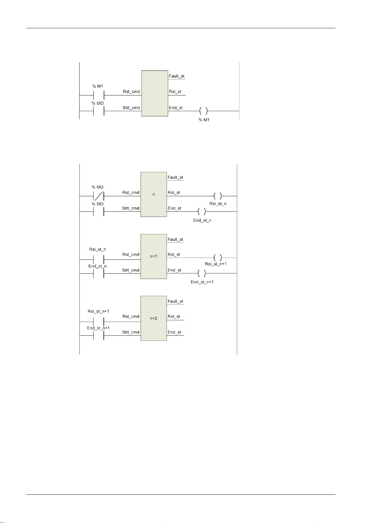
DFB Chaining with Manual Restart
In the DFB chaining with manual restart configuration, the DFB is linked to other DFBs and it is activated
each time %M0 is set to 1:
18
1672609EN-03 01/2020
Page 19
DFB Chaining with Automatic Restart
In the DFB chaining with automatic restart configuration, the DFB is linked to other DFBs and it is activated
continuously when %M0 is set to 1:
Introduction
1672609EN-03 01/2020 19
Page 20

Introduction
20
1672609EN-03 01/2020
Page 21

TeSys DFB Library V2 for Unity Pro
Modbus SL DFB
1672609EN-03 01/2020
Modbus SL DFB
Chapter 2
Modbus SL DFB
Introduction
This chapter describes the TeSys U and TeSys T Modbus SL (Serial Line) DFBs.
What Is in This Chapter?
This chapter contains the following topics:
Ctrl_cmd_mdb_u_••••: TeSys U Control/Command for Modbus SL 22
Comm_manager_u: TeSys U Communication Management for Modbus SL 26
Ctrl_cmd_mdb_t_••••: TeSys T Control/Command for Modbus SL 30
Comm_manager_t: TeSys T Communication Management for Modbus SL 34
Topic Page
1672609EN-03 01/2020 21
Page 22
Modbus SL DFB
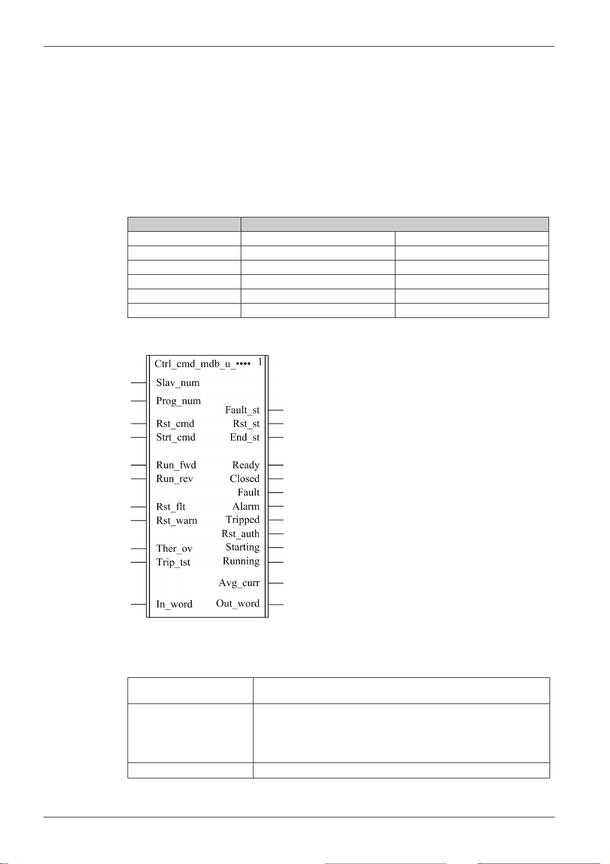
Ctrl_cmd_mdb_u_••••: TeSys U Control/Command for Modbus SL
Presentation
The Ctrl_cmd_mdb_u_•••• DFBs are dedicated to the control and command of a single TeSys U startercontroller with any control unit and a LULC033 Modbus communication module through the Modbus SL
(Serial Line) network.
Ctrl_cmd_mdb_u_addr uses XWAY addressing and is dedicated to Premium PLCs.
Ctrl_cmd_mdb_u_addm uses an addressing method dedicated to M340 PLCs.
For more information, see the
Characteristics
Characteristic Value
Name Ctrl_cmd_mdb_u_addr Ctrl_cmd_mdb_u_addm
Version 1.00 1.00
Input 11 11
Output 13 13
Input/Output 0 0
Public Variable 6 8
TeSys U LULC032-033 Modbus Communication Module User Manual
.
Graphical Representation
TeSys U Compliance
22
The Ctrl_cmd_mdb_u_•••• DFBs are compliant with the following TeSys U sub-assemblies:
Power base LUB•• non-reversing power base
LU2B•• reversing power base
Control unit
Communication module
LUCA standard control unit
LUCB and LUCD advanced control units
LUCC advanced control unit (up to 32 A/15 kW or 20 hp)
LUCL magnetic control unit
LUCM multifunction control unit (up to 32 A/15 kW or 20 hp)
LULC033 Modbus communication module
1672609EN-03 01/2020
Page 23
Software Implementation
The parameters and the inputs can only be changed if the End_st output variable is set to 1.
The output data is only valid if the End_st output variable is set to 1 and if there is no fault detected
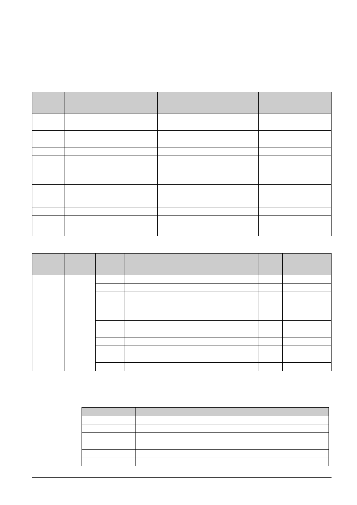
Input Characteristics
The following table describes the DFB inputs and their availability according to the control unit:
Modbus SL DFB
(Fault_st = 0).
Input Type Range Default Value Description LUCA
LUCL
Slav_num INT 1...31 1 Modbus slave number √ √ √
Prog_num INT 1...30 – See
Rst_cmd EBOOL 0...1 0 Reset command √ √ √
Strt_cmd EBOOL 0...1 0 Start command √ √ √
Run_fwd EBOOL 0...1 0 Motor run forward command √ √ √
Run_rev EBOOL 0...1 0 Motor run reverse command √ √ √
Rst_flt EBOOL 0...1 0 Reset device (if register 451 = 102 or 104, fault
Rst_warn EBOOL 0...1 0 Reset warning (for example, communication
Ther_ov EBOOL 0...1 0 Automatic thermal overload fault test – – √
Trip_tst EBOOL 0...1 0 Overcurrent trip test via communication bus – –√
In_word INT – – This input is only used when program number
Program Number, page 23
acknowledgment causes a return to
communication module factory settings)
loss)
is 10, 20, or 30. See next table and program
number description.
√√√
√√√
√√√
–––
LUCB
LUCC
LUCD
LUCM
The following table describes the In_word input:
Input Type Bit Description LUCA
LUCL
In_word INT 0 Motor run forward command √ √ √
1 Motor run reverse command √ √ √
2 Reserved – – –
3 Reset device (if register 451 = 102 or 104, fault
acknowledgment causes a return to communication module
factory settings)
4 Reserved – – –
5 Automatic thermal overload fault test – – √
6 Overcurrent trip test via communication bus – – √
7 Reserved – – –
8 Reset warning (for example, communication loss) √ √ √
9...15 Reserved – – –
√√√
LUCB
LUCC
LUCD
LUCM
Program Number
The program number enables the user to select bit or word control.
The following table describes the programs of the DFB:
Program Number Description
1 Read registers 455 and 456, then write register 704 (systematic)
2 Read registers 455 and 456, then write register 704 (conditional)
3 Write register 704
10 Same as program 1 but using the In_word input and the Out_word output
20 Same as program 2 but using the In_word input and the Out_word output
30 Same as program 3 but using the In_word input and the Out_word output
1672609EN-03 01/2020 23
Page 24
Modbus SL DFB
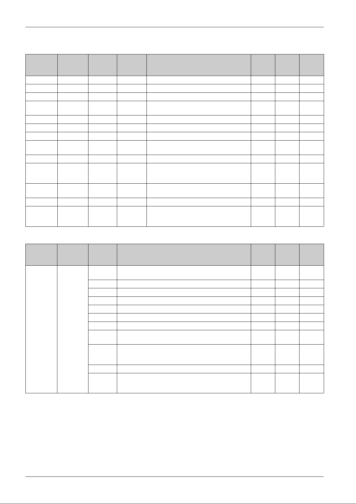
Output Characteristics
The following table describes the DFB outputs and their availability according to the control unit:
Output Type Range Default
Value
Fault_st EBOOL 0...1 0 Fault detected √ √ √
Rst_st EBOOL 0...1 0 Reset state √ √ √
End_st EBOOL 0...1 0 End state √ √ √
Ready EBOOL 0...1 0 System ready: the rotary handle is turned to On
Closed EBOOL 0...1 0 Pole status: closed √ √ √
Fault EBOOL 0...1 0 All faults √ √ √
Alarm EBOOL 0...1 0 All warnings √ √ √
Tripped EBOOL 0...1 0 System tripped: the rotary handle is turned to
Rst_auth EBOOL 0...1 0 Fault reset authorized – √ √
Starting EBOOL 0...1 0 Start in progress:
Running EBOOL 0...1 0 Motor running with detection of current, if
Avg_curr INT 0...200 0 Average motor current (x 1% FLA) – √ √
Out_word INT – – This output is only used when program number
Description LUCA
LUCL
√√√
position and there is no fault
√√√
Trip position
–√√
0 = descending current is lower than 150% FLA
1 = ascending current is greater than 10% FLA
–√√
greater than 10% FLA
–––
is 10, 20, or 30. See next table and program
number description.
LUCB
LUCC
LUCD
LUCM
The following table describes the Out_word output:
Output Type Bit Description LUCA
LUCL
Out_word INT 0 System ready: the rotary handle is turned to On position and
there is no fault.
1 Pole status: closed √ √ √
2 All faults √ √ √
3 All warnings √ √ √
4 System tripped: the rotary handle is turned to Trip position. √ √√
5 Fault reset authorized – √ √
6 Reserved – – –
7 Motor running with detection of current, if greater than
10% FLA
8...13 Average motor current (% FLA)
32 = 100% FLA
63 = 200% FLA
14 Reserved – – –
15 Start in progress:
0 = descending current is lower than 150% FLA
1 = ascending current is greater than 10% FLA
√√√
–√√
–√√
–√√
LUCB
LUCC
LUCD
LUCM
24
1672609EN-03 01/2020
Page 25

Public Variables Characteristics
The following table describes the Ctrl_cmd_mdb_u_addr DFB public variables (using XWAY addressing)
and their availability according to the control unit:
Modbus SL DFB
Public Variable Type Range Default
Value
Net_num INT 0...255 0 Network address √ √ √
Stat_num INT 0...255 0 Station address √ √ √
Rack_num INT 0...7 0 Destination rack address √ √ √
Slot_num INT 0...10 0 Destination slot address √ √ √
Chan_num INT 0...1 0 Destination channel address √ √ √
Sq_princ INT 0...7 0 Reserved for support √ √ √
Description LUCA
LUCL
LUCB
LUCC
LUCD
The following table describes the Ctrl_cmd_mdb_u_addm DFB public variables (using M340 addressing)
and their availability according to the control unit:
Public Variable Type Range Default
Value
Rack_num INT 0...7 0 Destination rack address √ √ √
Slot_num INT 0...10 0 Destination slot address √ √ √
Chan_num INT 0...1 0 Destination channel address √ √ √
IP_addr1 INT 0...255 0 First byte of IP address √ √ √
IP_addr2 INT 0...255 0 Second byte of IP address √ √ √
IP_addr3 INT 0...255 0 Third byte of IP address √ √ √
IP_addr4 INT 0...255 0 Fourth byte of IP address √ √ √
Sq_princ INT 0...7 0 Reserved for support √ √ √
Description LUCA
LUCL
LUCB
LUCC
LUCD
LUCM
LUCM
1672609EN-03 01/2020 25
Page 26
Modbus SL DFB
Comm_manager_u: TeSys U Communication Management for Modbus SL
Presentation
The Comm_manager_u DFB is dedicated to the control and command of up to 31 TeSys U startercontrollers with any control unit and a LULC033 Modbus communication module though the Modbus SL
(Serial Line) network. It must be associated with the Ctrl_cmd_mdb_u_•••• DFBs to manage the Modbus
requests sequencing.
The number of TeSys U Modbus slaves is defined in the Slav_num variable (Slav_num = 1...31).
For more information, see the
Characteristics
Characteristic Value
Name Comm_manager_u
Version 1.00
Input 4
Output 4
Input/Output 0
Public Variable 3
TeSys U LULC032-033 Modbus Communication Module User Manual
.
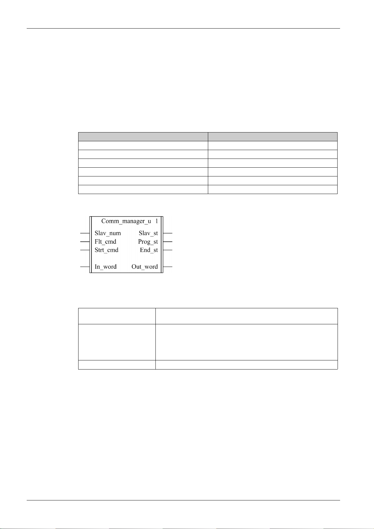
Graphical Representation
TeSys U Compliance
The Comm_manager_u DFB is compliant with the following TeSys U sub-assemblies:
Power base LUB•• non-reversing power base
Control unit
Communication module
LU2B•• reversing power base
LUCA standard control unit
LUCB and LUCD advanced control units
LUCC advanced control unit (up to 32 A/15 kW or 20 hp)
LUCL magnetic control unit
LUCM multifunction control unit (up to 32 A/15 kW or 20 hp)
LULC033 Modbus communication module
26
1672609EN-03 01/2020
Page 27
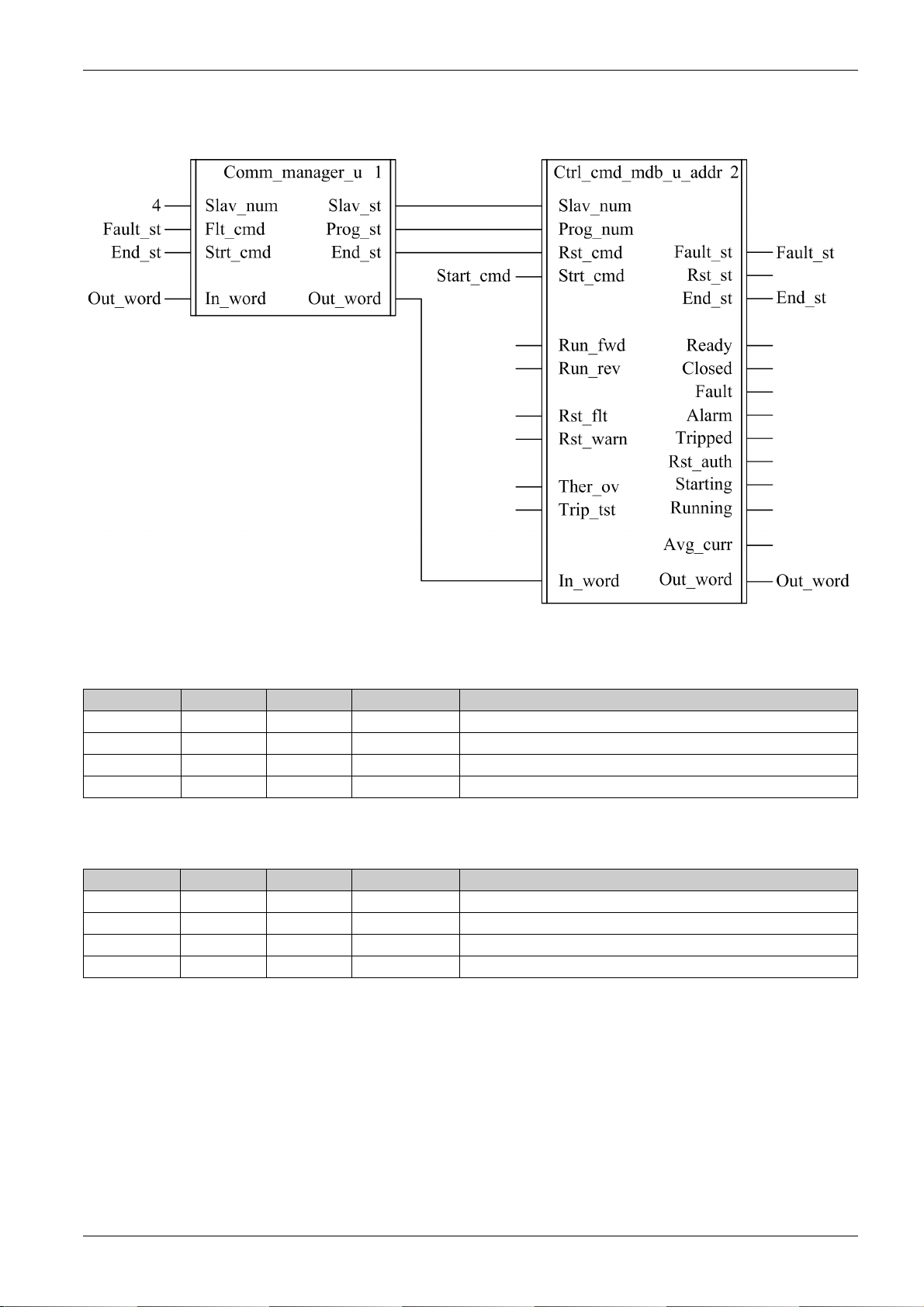
Software Implementation
The following figure shows a Unity Pro program extract in FBD language showing how to interconnect the
Ctrl_cmd_mdb_u_addr and the Comm_manager_u DFBs:
Modbus SL DFB
Input Characteristics
The following table describes the DFB inputs:
Input Type Range Default Value Description
Slav_num INT 1...31 1 Modbus slave number
Flt_cmd EBOOL 0...1 0 Reset command
Strt_cmd EBOOL 0...1 0 Start command
In_word INT – – To connect to the Out_word output of the Ctrl_cmd_mdb_u_•••• DFB
Output Characteristics
The following table describes the DFB outputs:
Output Type Range Default Value Description
Slav_st INT 1...31 1 Modbus slave number
Prog_st INT 20 or 30 – Program number of the Ctrl_cmd_mdb_u_•••• DFB
End_st EBOOL 0...1 0 End state
Out_word INT – – To connect to the In_word input of the Ctrl_cmd_mdb_u_•••• DFB
1672609EN-03 01/2020 27
Page 28

Modbus SL DFB
Public Variables Characteristics
The following table describes the DFB public variables:
Public Variable Type Range Default Value Description
In_cmd[0]...[31] ARRAY [0...31] of INT – – See
In_cmd[0]...[31] Public Variable,
page 28
Out_urg INT – – Priority level
Out_st[0]...[31] ARRAY [0...31] of INT – – See
Bit 0 = Pulling
Bit 1 = Writing priority
Bit 2 = Reading priority
Bit 3 = Fault priority
Out_st[0]...[31] Public Variable,
page 29
In_cmd[0]...[31] Public Variable
The In_cmd[0]...[31] public variable is a table of 32 words corresponding to the TeSys U Modbus slave
address. The following table describes the In_cmd[0]...[31] public variable:
Public Variable Type Bit Description Corresponding to the TeSys U
Slave 1...31
In_cmd[0] INT – Not significant – – –
In_cmd[1]...[31] INT 0 Motor run forward command √ √ √
1 Motor run reverse command √ √ √
2 Reserved – – –
3 Reset device
(if register 451 = 102 or 104, fault
acknowledgment causes a return to
communication module factory settings)
4 Reserved – – –
5 Automatic thermal overload fault test – – √
6 Overcurrent trip test via communication bus – – √
7 Reserved – – –
8 Reset warning (for example, communication
loss)
9...15 Reserved – – –
LUCA
LUCL
√√√
√√√
LUCB
LUCC
LUCD
LUCM
28
1672609EN-03 01/2020
Page 29

Out_st[0]...[31] Public Variable
The Out_st[0]...[31] public variable is a table of 32 words corresponding to the TeSys U Modbus slave
address.The following table describes the Out_st[0]....[31] public variable:
Modbus SL DFB
Public Variable Type Bit Description Corresponding to the TeSys U Slave
1...31
Out_st[0] INT – Not significant – – –
Out_st[1]...[31] INT 0 System ready: the rotary handle is turned to On
position and there is no fault.
1 Pole status: closed √ √ √
2 All faults √ √ √
3 All warnings √ √ √
4 System tripped: the rotary handle is turned to Trip
position.
5 Fault reset is authorized – √ √
6Reserved – – –
7 Motor running with detection of current, if greater
than 10% FLA
8...13 Average motor current (% FLA)
32 = 100% FLA
63 = 200% FLA
14 Reserved – – –
15 Start in progress:
1 = ascending current is greater than 10% FLA
0 = descending current is lower than 150% FLA
LUCA
LUCL
√√ √
√√ √
–√√
–√√
–√√
LUCB
LUCC
LUCD
LUCM
1672609EN-03 01/2020 29
Page 30
Modbus SL DFB
Ctrl_cmd_mdb_t_••••: TeSys T Control/Command for Modbus SL
Presentation
The Ctrl_cmd_mdb_t_•••• DFBs are dedicated to the control and command of a single TeSys T LTMR••M••
Modbus SL controller with or without the LTM E expansion module through the Modbus SL network.
Ctrl_cmd_mdb_t_addr uses XWAY addressing and is dedicated to Premium PLCs
Ctrl_cmd_mdb_t_addm uses an addressing method dedicated to M340 PLCs
For more information, see the
Characteristics
Characteristic Value
Name Ctrl_cmd_mdb_t_addr Ctrl_cmd_mdb_t_addm
Version 1.00 1.00
Input 10 10
Output 24 24
Input/Output 0 0
Public Variable 6 8
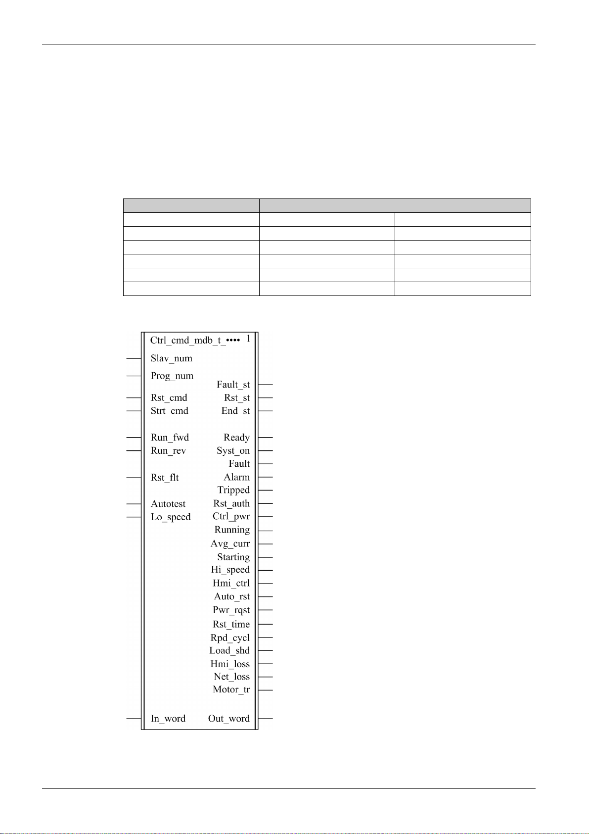
Graphical Representation
TeSys T LTMR Modbus Communication Guide
.
30
1672609EN-03 01/2020
Page 31

Modbus SL DFB
TeSys T Compliance
The Ctrl_cmd_mdb_t_•••• DFBs are compliant with all the TeSys T LTM R••M•• controller versions, with or
without the LTM E expansion module.
Software Implementation
The parameters and the inputs can only be changed if the End_st output variable is set to 1.
The output data is only valid if the End_st output variable is set to 1 and if there is no fault detected
(Fault_st = 0).
Input Characteristics
The following table describes the DFB inputs:
Input Type Range Default Value Description
Slav_num INT 1...31 1 Modbus slave number
Prog_num INT 1...30 – See
Rst_cmd EBOOL 0...1 0 Reset command
Strt_cmd EBOOL 0...1 0 Start command
Run_fwd EBOOL 0...1 0 Motor run forward command
Run_rev EBOOL 0...1 0 Motor run reverse command
Rst_flt EBOOL 0...1 0 Fault reset command
Autotest EBOOL 0...1 0 Self test command
Lo_speed EBOOL 0...1 0 Motor low speed command
In_word INT – – This input is only used when program number is 10, 20,
Program Number, page 31
or 30. See next table and program number description.
The following table describes the In_word input:
Input Type Bit Description
In_word INT 0 Motor run forward command
1 Motor run reverse command
2 Reserved
3 Fault reset command
4 Reserved
5 Self test command
6 Motor low speed command
7...15 Reserved
Program Number
The program number enables the user to select bit or word control.
The following table describes the programs of the DFB:
Program Number Description
1 Read registers 455 and 456, then write register 704 (systematic)
2 Read registers 455 and 456, then write register 704 (conditional)
3 Write register 704
10 Same as program 1 but using the In_word input and the Out_word output
20 Same as program 2 but using the In_word input and the Out_word output
30 Same as program 3 but using the In_word input and the Out_word output
1672609EN-03 01/2020 31
Page 32

Modbus SL DFB
Output Characteristics
The following table describes the DFB outputs:
Output Type Range Default Value Description
Fault_st EBOOL 0...1 0 Fault detected
Rst_st EBOOL 0...1 0 Reset state
End_st EBOOL 0...1 0 End state
Ready EBOOL 0...1 0 System ready
Syst_on EBOOL 0...1 0 System On
Fault EBOOL 0...1 0 System fault
Alarm EBOOL 0...1 0 System warning
Tripped EBOOL 0...1 0 System tripped
Rst_auth EBOOL 0...1 0 Fault reset authorized
Ctrl_pwr EBOOL 0...1 0 Controller power
Running EBOOL 0...1 0 Motor running (with detection of a current, if greater than 10% FLC)
Avg_curr INT 0...200 0 Motor average current ratio (x 1% FLC)
Starting EBOOL 0...1 0 Motor starting (start in progress)
0 = descending current is less than 150% FLC
1 = ascending current is greater than 10% FLC
Hi_speed EBOOL 0...1 0 Motor high speed
Hmi_ctrl EBOOL 0...1 0 Control through HMI
Auto_rst EBOOL 0...1 0 Auto-reset active
Pwr_rqst EBOOL 0...1 0 Power cycle requested
Rst_Time EBOOL 0...1 0 Motor restart time undefined
Rpd_cycl EBOOL 0...1 0 Rapid cycle lockout
Load_shd EBOOL 0...1 0 Load shedding
Hmi_loss EBOOL 0...1 0 HMI port communication loss
Net_loss EBOOL 0...1 0 Network port communication loss
Motor_tr EBOOL 0...1 0 Motor transition lockout
Out_word DINT – – This output is only used when program number is 10, 20, or 30. See
next table and program number description.
32
1672609EN-03 01/2020
Page 33

The following table describes the Out_word output:
Output Type Bit Description
Out_word DINT 0 System ready
1System On
2 System fault
3System warning
4 System tripped
5 Fault reset authorized
6 Controller power
7 Motor running (with detection of a current, if greater than 10%FLC)
8...13 Motor average current ratio
32 = 100% FLC
63 = 200% FLC
14 Control through HMI
15 Motor starting (start in progress)
0 = descending current is less than 150% FLC
1 = ascending current is greater than 10% FLC
16 Auto-reset active
17 Not significant
18 Power cycle requested
19 Motor restart time undefined
20 Rapid cycle lockout
21 Load shedding
22 Motor speed
0 = FLC1 setting is used
1 = FLC2 setting is used
23 HMI port communication loss
24 Network port communication loss
25 Motor transition lockout
26...31 Not significant
Modbus SL DFB
Public Variables Characteristics
The following table describes the Ctrl_cmd_mdb_t_addr DFB public variables (using XWAY addressing):
Public Variable Type Range Default Value Description
Net_num INT 0...255 0 Network address
Stat_num INT 0...255 0 Station address
Rack_num INT 0...7 0 Destination rack address
Slot_num INT 0...10 0 Destination slot address
Chan_num INT 0...1 0 Destination channel address
Sq_princ INT 0...7 0 Reserved for support
The following table describes the Ctrl_cmd_mdb_t_addm DFB public variables (using M340 addressing):
Public Variable Type Range Default Value Description
Rack_num INT 0...7 0 Destination rack address
Slot_num INT 0...10 0 Destination slot address
Chan_num INT 0...1 0 Destination channel address
IP_addr1 INT 0...255 0 First byte of IP address
IP_addr2 INT 0...255 0 Second byte of IP address
IP_addr3 INT 0...255 0 Third byte of IP address
IP_addr4 INT 0...255 0 Fourth byte of IP address
Sq_princ INT 0...7 0 Reserved for support
1672609EN-03 01/2020 33
Page 34

Modbus SL DFB
Comm_manager_t: TeSys T Communication Management for Modbus SL
Presentation
The Comm_manager_t DFB is dedicated to the control and command of up to 31 TeSys T LTMR••M••
Modbus SL controllers with or without the LTM E expansion module through the Modbus SL network. It
must be associated with the Ctrl_cmd_mdb_t_•••• DFB to manage the Modbus requests sequencing.
The number of TeSys T Modbus slaves is define din the Slav_num variable (Slav_num = 1...31).
For more information, see the
Characteristics
Characteristic Value
Name Comm_manager_t
Version 1.0
Input 4
Output 4
Input/Output 0
Public Variable 3
Graphical Representation
TeSys T LTMR Modbus Communication Guide
.
TeSys T Compliance
The Comm_manager_t DFB is compliant with all the TeSys T LTM R••M•• controller versions, with or
without the LTM E expansion module.
34
1672609EN-03 01/2020
Page 35

Software Implementation
The following figure shows a Unity Pro program extract in FBD language showing how to interconnect the
Ctrl_cmd_mdb_t and the Comm_manager_t DFBs:
Modbus SL DFB
The Comm_manager_t DFB can be used in case both TeSys U starter-controllers and TeSys T motor
management systems are present on the same Modbus SL network.
Input Characteristics
The following table describes the DFB inputs:
Input Type Range Default Value Description
Slav_num INT 1...31 1 Modbus slave number
Flt_cmd EBOOL 0...1 0 Reset command
Strt_cmd EBOOL 0...1 0 Start command
In_word DINT – – To connect to the Out_word output of the Ctrl_cmd_mdb_t_••••
1672609EN-03 01/2020 35
DFB
Page 36

Modbus SL DFB
Output Characteristics
The following table describes the DFB outputs:
Output Type Range Default Value Description
Slav_st INT 1...31 1 Modbus slave number
Prog_st INT 20 or 30 – Program number of the Ctrl_cmd_mdb_t_•••• DFB
End_st EBOOL 0...1 0 End state
Out_word INT – – To connect to the In_word input of the Ctrl_cmd_mdb_t_••••
DFB
Public Variables Characteristics
The following table describes the DFB public variables:
Public Variable Type Range Default Value Description
In_cmd[0]...[31] ARRAY [0...31] of INT – – See
Out_urg INT – – Priority level
Out_st[0]...[31] ARRAY [0...31] of DINT – – See
In_cmd[0]...[31] Public Variable, page 36
Bit 0 = Pulling
Bit 1 = Writing priority
Bit 2 = Reading priority
Bit 3 = Fault priority
Out_st[0]...[31] Public Variable, page 37
In_cmd[0]...[31] Public Variable
The In_cmd[0]...[31] public variable is a table of 32 words corresponding to the TeSys T Modbus slave
address. The following table describes the In_cmd[0]...[31] public variable:
Public Variable Type Bit Description Corresponding to the TeSys T Slave 1...31
In_cmd[0] INT – Not significant
In_cmd[1]...[31] INT 0 Motor run forward command
1 Motor run reverse command
2 Reserved
3 Fault reset command
4 Reserved
5 Self test command
6 Motor low speed command
7...31 Reserved
36
1672609EN-03 01/2020
Page 37

Out_st[0]...[31] Public Variable
The Out_st[0]...[31] public variable is a table of 32 words corresponding to the TeSys T Modbus slave
address.The following table describes the Out_st[0]....[31] public variable:
Public Variable Type Bit Description Corresponding to the TeSys T
Slave 1...31
Out_st[0] DINT – Not significant
Out_st[1]...[31] DINT 0 System ready
1System On
2 System fault
3System warning
4 System tripped
5 Fault reset authorized
6 Controller power
7 Motor running (with detection of a current, if greater than 10%FLC)
8...13 Motor average current ratio
32 = 100% FLC
63 = 200% FLC
14 Control through HMI
15 Motor starting (start in progress)
0 = descending current is less than 150% FLC
1 = ascending current is greater than 10% FLC
16 Auto-reset active
17 Not significant
18 Power cycle requested
19 Motor restart time undefined
20 Rapid cycle lockout
21 Load shedding
22 Motor speed
0 = FLC1 setting is used
1 = FLC2 setting is used
23 HMI port communication loss
24 Network port communication loss
25 Motor transition lockout
26...31 Not significant
Modbus SL DFB
1672609EN-03 01/2020 37
Page 38

Modbus SL DFB
The Out_st[0]...[31] public variable is a table of 32 words corresponding to the TeSys T Modbus slave
address.The following table describes the Out_st[0]....[31] public variable:
Public Variable Type Bit Description Corresponding to the TeSys T
Slave 1...31
Out_st[0] DINT – Not significant
Out_st[1]...[31] DINT 0 System ready
1System On
2 System fault
3System warning
4 System tripped
5 Fault reset authorized
6 Controller power
7 Motor running (with detection of a current, if greater than 10%FLC)
8...13 Motor average current ratio
32 = 100% FLC
63 = 200% FLC
14 Control through HMI
15 Motor starting (start in progress)
0 = descending current is less than 150% FLC
1 = ascending current is greater than 10% FLC
16 Auto-reset active
17 Not significant
18 Power cycle requested
19 Motor restart time undefined
20 Rapid cycle lockout
21 Load shedding
22 Motor speed
0 = FLC1 setting is used
1 = FLC2 setting is used
23 HMI port communication loss
24 Network port communication loss
25 Motor transition lockout
26...31 Not significant
38
1672609EN-03 01/2020
Page 39

TeSys DFB Library V2 for Unity Pro
Modbus SL and Modbus/T CP DFB
1672609EN-03 01/2020
Modbus SL and Modbus/TCP DFB
Chapter 3
Modbus SL and Modbus/TCP DFB
Introduction
This chapter describes the TeSys U and TeSys T Modbus SL and Modbus/TCP DFBs dedicated to
Premium and M340 PLCs.
What Is in This Chapter?
This chapter contains the following topics:
Special_mdb_u_••••: TeSys U DFB for Modbus SL and Modbus/TCP 40
Special_mdb_t_••••: TeSys T DFB for Modbus SL and Modbus/TCP 46
Custom_mdb_••••: Custom Read DFB for Modbus SL and Modbus/TCP 58
Topic Page
1672609EN-03 01/2020 39
Page 40

Modbus SL and Modbus/TCP DFB
Special_mdb_u_••••: TeSys U DFB for Modbus SL and Modbus/TCP
Presentation
The Special_mdb_u_•••• DFBs are dedicated to the reading of up to 16 predefined registers of a TeSys U
starter-controller (up to 32 A/15 kW or 20 hp) equipped with a LUCM multifunction control unit and a
LULC033 Modbus communication module directly through a Modbus SL network or through an Ethernet
gateway with a Modbus/TCP network.
Special_mdb_u_addr uses XWAY addressing and is dedicated to Premium PLCs and can be used with
a TeSys U starter-controller connected on Modbus Serial Line or through a Modbus/TCP gateway.
Special_mdb_u_addm uses an addressing method dedicated to M340 PLCs and can be used with a
TeSys U starter-controller connected on Modbus Serial Line or through a Modbus/TCP gateway.
For more information, see the
Characteristics
Characteristic Value
Name Special_mdb_u_addr Special_mdb_u_addm
Version 1.00 and 1.10 1.00 and 1.10
Input 4 4
Output 3 3
Input/Output 0 0
Public Variable 7 9
TeSys U LULC032-033 Modbus Communication Module User Manual
.
Graphical Representation
TeSys U Compliance
The Special_mdb_u_•••• DFBs are compliant with the following TeSys U sub-assemblies:
Power base LUB•• non-reversing power base (up to 32 A/15 kW or 20 hp)
Control unit
Communication module
Software Implementation
The parameters and the inputs can only be changed if the End_st output variable is set to 1.
With version 1.00:
The output data is only valid if the End_st output variable is set to 1 and if there is no fault detected
(Fault_st = 0).
With version 1.10:
The output data is only valid if there is no fault detected (Fault_st = 0).
Prog_num input can be modified on the fly.
LU2B•• reversing power base (up to 32 A/15 kW or 20 hp)
LUCM multifunction control unit
LULC033 Modbus communication module
40
1672609EN-03 01/2020
Page 41

Input Characteristics
The following table describes the DFB inputs:
Input Type Range Default Value Description
Slav_num INT 1...31 1 Modbus slave number
Prog_num INT 0...6 0 Program number
See
Program Number, page 41
Rst_cmd EBOOL 0...1 0 Reset command
Strt_cmd EBOOL 0...1 0 Start command
Output Characteristics
The following table describes the DFB outputs:
Output Type Range Default Value Description
Fault_st EBOOL 0...1 0 Fault detected
Rst_st EBOOL 0...1 0 Reset state
End_st EBOOL 0...1 0 End state
Program Number
The Prog_num input variable enables the user to define the public variables data depending on the
application type. Each program uses variables related to one application (diagnostic, maintenance,
measurement,...). The following table describes the programs of the DFB:
Modbus SL and Modbus/TCP DFB
Program Number Description
0 Bypass: no action
1 Diagnostic: faults monitoring variables, warnings monitoring variables, and communication monitoring variables
2 Maintenance: global statistics variables
3 Measurements: measurements monitoring variables
4 Statistics: last trip statistics and trip N–1 statistics
5 Statistics: trip N–2 statistics and trip N–3 statistics
6 Statistics: trip N–4 statistics
Public Variables Characteristics
The following table describes the Special_mdb_u_addr DFBs public variables (using XWAY addressing):
Public Variable Type Range Default Value Description
Net_num INT 0...255 0 Network address
Stat_num INT 0...255 0 Station address
Rack_num INT 0...7 0 Destination rack address
Slot_num INT 0...10 0 Destination slot address
Chan_num INT 0...1 0 Destination channel address
Sq_princ INT 0...7 0 Reserved for support
Out_data[0]...[15] ARRAY [0...15] of
INT
0...65535 0 The output data depends on the program number.
Out_data[0]...[15] Public Variable (Program
See
1), page 42
...
Out_data[0]...[15] Public Variable
(Program 6), page 45
The following table describes the Special_mdb_u_addm DFB public variables (using M340 addressing):
Public Variable Type Range Default Value Description
Rack_num INT 0...7 0 Destination rack address
Slot_num INT 0...10 0 Destination slot address
Chan_num INT 0...1 0 Destination channel address
IP_addr1 INT 0...255 0 First byte of IP address
IP_addr2 INT 0...255 0 Second byte of IP address
IP_addr3 INT 0...255 0 Third byte of IP address
1672609EN-03 01/2020 41
Page 42

Modbus SL and Modbus/TCP DFB
Public Variable Type Range Default Value Description
IP_addr4 INT 0...255 0 Fourth byte of IP address
Sq_princ INT 0...7 0 Reserved for support
Out_data[0]...[15] ARRAY [0...15] of INT 0...65535 0 The output data depends on the program number.
Out_data[0]...[15] Public Variable (Program 1),
See
page 42
...
Out_data[0]...[15] Public Variable
(Program 6), page 45
Out_data[0]...[15] Public Variable (Program 1)
The following table describes the Out_data[0]...[15] public variable in the case of the diagnostic program
(program number 1):
Public Variable Type Register Bit Description
Out_data[0] INT 452 0 Short-circuit fault
1 Magnetic fault
2 Ground fault
3 Thermal fault
4 Long start fault
5 Jam fault
6 Phase imbalance fault
7 Underload fault
8 Shunt trip fault
9 Test trip fault
10 Communication loss fault on LUCM Modbus port
11 Control unit internal fault
12 Module identification or internal communication fault
13 Module internal fault
14 Module trip fault
15 Module drop-out fault
Out_data[1] INT 461 0...1 Not significant
2 Ground fault warning
3 Thermal warning
4 Long start warning
5 Jam warning
6 Phase imbalance warning
7 Under-current warning
8...9 Not significant
10 Communication loss fault on LUCM Modbus port
11 Internal temperature warning
12 Module identification or internal communication warning
13...14 Not significant
15 Module warning
Out_data[2] INT 457 0 Button position On (0 = Off)
1 Button position Trip (0 = Not tripped)
2 Contactor state On
3 24 Vdc power supply present on outputs
4...15 Not significant
Out_data[3] INT 450 – Time to automatic reset on a thermal fault (s)
Out_data[4]
...Out_data[15]
– – – Not significant
42
1672609EN-03 01/2020
Page 43

Out_data[0]...[15] Public Variable (Program 2)
The following table describes the Out_data[0]...[15] public variable in the case of the maintenance program
(program number 2):
Public Variable Type Register Description
Out_data[0] INT 100 Short-circuit faults count
Out_data[1] INT 101 Magnetic faults count
Out_data[2] INT 102 Ground faults count
Out_data[3] INT 103 Thermal faults count
Out_data[4] INT 104 Long start faults count
Out_data[5] INT 105 Jam faults count
Out_data[6] INT 106 Phase imbalance faults count
Out_data[7] INT 108 Shunt trip faults count
Out_data[8] INT 115 Auto-resets count
Out_data[9] INT 116 Thermal warnings count
Out_data[10] INT 117 Starts count (LSB)
Out_data[11] INT 118 Starts count (MSB)
Out_data[12] INT 119 Operating time (LSB)
Out_data[13] INT 120 Operating time (MSB)
Out_data[14] INT 121 Maximum internal temperature (°C)
Out_data[15] – – Not significant
Modbus SL and Modbus/TCP DFB
Out_data[0]...[15] Public Variable (Program 3)
The following table describes the Out_data[0]...[15] public variable in the case of the measurements
program (program number 3):
Public Variable Type Register Description
Out_data[0] – – Not significant
Out_data[1] INT 465 Thermal capacity level (%)
Out_data[2] INT 466 Average motor current (x 0.1 % FLA)
Out_data[3] INT 467 L1 current (% FLA)
Out_data[4] INT 468 L2 current (% FLA)
Out_data[5] INT 469 L3 current (% FLA)
Out_data[6] INT 470 Ground current (% FLA min)
Out_data[7] INT 471 Current imbalance coefficient
Out_data[8] INT 472 Control unit internal temperature (°C)
Out_data[9]
...Out_data[13]
Out_data[14] INT 79 Control unit sensor maximum current (x 0.1 A):
Out_data[15] INT 652 Full load amps setting (% FLA max):
– – Not significant
6 = adjustment range 0.15–0.6 A
14 = adjustment range 0.35–.4 A
50 = adjustment range 1.25–5 A
120 = adjustment range 3–12 A
180 = adjustment range 4.5–18 A
320 = adjustment range 8–32 A
minimum = 25 (default value)
maximum = 100
1672609EN-03 01/2020 43
Page 44

Modbus SL and Modbus/TCP DFB
Out_data[0]...[15] Public Variable (Program 4)
The following table describes the Out_data[0]...[15] public variable in the case of the statistics program
(program number 4):
Public Variable Type Register Description
Out_data[0] INT 150 Last trip fault number
Out_data[1] INT 152 Last trip thermal capacity level (% trip level)
Out_data[2] INT 153 Last trip average current (% FLA)
Out_data[3] INT 154 Last trip L1 current (% FLA)
Out_data[4] INT 155 Last trip L2 current (% FLA)
Out_data[5] INT 156 Last trip L3 current (% FLA)
Out_data[6] INT 157 Last trip ground current (% FLA min)
Out_data[7] INT 180 N1 trip fault number
Out_data[8] INT 182 N–1 trip thermal capacity level (% trip level)
Out_data[9] INT 183 N–1 trip average current (% FLA)
Out_data[10] INT 184 N–1 trip L1 current (% FLA)
Out_data[11] INT 185 N–1 trip L2 current (%FLA)
Out_data[12] INT 186 N–1 trip L3 current (% FLA)
Out_data[13] INT 187 N–1 trip ground current (% FLA min)
Out_data[14] INT 79 Control unit sensor maximum current (x 0.1 A):
Out_data[15] INT 652 Full load amps setting (% FLA max):
6 = adjustment range 0.15–0.6 A
14 = adjustment range 0.35–1.4 A
50 = adjustment range 1.25–5 A
120 = adjustment range 3–12 A
180 = adjustment range 4.5–18 A
320 = adjustment range 8–32 A
minimum = 25 (default value)
maximum = 100
44
1672609EN-03 01/2020
Page 45

Out_data[0]...[15] Public Variable (Program 5)
The following table describes the Out_data[0]...[15] public variable in the case of the statistics program
(program number 5):
Public Variable Type Register Description
Out_data[0] INT 210 N–2 trip fault number
Out_data[1] INT 212 N–2 trip thermal capacity level (% trip level)
Out_data[2] INT 213 N–2 trip average current (% FLA)
Out_data[3] INT 214 N–2 trip L1 current (% FLA)
Out_data[4] INT 215 N–2 trip L2 current (% FLA)
Out_data[5] INT 216 N–2 trip L3 current (% FLA)
Out_data[6] INT 217 N–2 trip ground current (% FLA min)
Out_data[7] INT 240 N–3 trip fault number
Out_data[8] INT 242 N–3 trip thermal capacity level (% trip level)
Out_data[9] INT 243 N–3 trip average current (% FLA)
Out_data[10] INT 244 N–3 trip L1 current (% FLA)
Out_data[11] INT 245 N–3 trip L2 current (%FLA)
Out_data[12] INT 246 N–3 trip L3 current (% FLA)
Out_data[13] INT 247 N–3 trip ground current (% FLA min)
Out_data[14] INT 79 Control unit sensor maximum current (x 0.1 A):
6 = adjustment range 0.15–0.6 A
14 = adjustment range 0.35–1.4 A
50 = adjustment range 1.25–5 A
120 = adjustment range 3–12 A
180 = adjustment range 4.5–18 A
320 = adjustment range 8–32 A
Out_data[15] INT 652 Full load amps setting (% FLA max):
minimum = 25 (default value)
maximum = 100
Modbus SL and Modbus/TCP DFB
Out_data[0]...[15] Public Variable (Program 6)
The following table describes the Out_data[0]...[15] public variable in the case of the statistics program
(program number 6):
Public Variable Type Register Description
Out_data[0] INT 270 N–4 trip fault number
Out_data[1] INT 272 N–4 trip thermal capacity level (% trip level)
Out_data[2] INT 273 N–4 trip average current (% FLA)
Out_data[3] INT 274 N–4 trip L1 current (% FLA)
Out_data[4] INT 275 N–4 trip L2 current (% FLA)
Out_data[5] INT 276 N–4 trip L3 current (% FLA)
Out_data[6] INT 277 N–4 trip ground current (% FLA min)
Out_data[7]
...Out_data[13]
Out_data[14] INT 79 Control unit sensor maximum current (x 0.1 A):
Out_data[15] INT 652 Full load amps setting (% FLA max):
–– Reserved
6 = adjustment range 0.15–0.6 A
14 = adjustment range 0.35–1.4 A
50 = adjustment range 1.25–5 A
120 = adjustment range 3–12 A
180 = adjustment range 4.5–18 A
320 = adjustment range 8–32 A
minimum = 25 (default value)
maximum = 100
1672609EN-03 01/2020 45
Page 46

Modbus SL and Modbus/TCP DFB
Special_mdb_t_••••: TeSys T DFB for Modbus SL and Modbus/TCP
Presentation
The Special_mdb_t_•••• DFBs are dedicated to the reading of up to 16 predefined registers of a TeSys T
LTM R••M•• controller through the Modbus SL network or a TeSys T LTM R••E•• controller through the
Modbus/TCP network.
Special_mdb_t_addr uses XWAY addressing and is dedicated to Premium PLCs.
Special_mdb_t_addm uses an addressing method dedicated to M340 PLCs.
For more information, see:
TeSys T LTM R Modbus Communication Guide
TeSys T LTM R Ethernet Communication Guide
Characteristics
Characteristic Value
Name Special_mdb_t_addr Special_mdb_t_addm
Version 1.00 and 1.10 1.00 and 1.10
Input 4 4
Output 3 3
Input/Output 0 0
Public Variable 7 9
Graphical Representation
TeSys T Compliance
The Special_mdb_t_•••• DFBs are compliant with all the TeSys T LTM R••M•• and LTM R••E•• controller
versions, with or without the LTM E expansion module.
Software Implementation
The parameters and the inputs can only be changed if the End_st output variable is set to 1.
With version 1.00:
The output data is only valid if the End_st output variable is set to 1 and if there is no fault detected
(Fault_st = 0).
With version 1.10:
The output data is only valid if there is no fault detected (Fault_st = 0).
Prog_num input can be modified on the fly.
Input Characteristics
The following table describes the DFB inputs:
Input Type Range Default Value Description
Slav_num INT 1...31 1 Modbus slave number
Prog_num INT 0...6 0 Program number
Rst_cmd EBOOL 0...1 0 Reset command
Strt_cmd EBOOL 0...1 0 Start command
46
Program Number, page 47
See
1672609EN-03 01/2020
Page 47

Modbus SL and Modbus/TCP DFB
Output Characteristics
The following table describes the DFB outputs:
Output Type Range Default Value Description
Fault_st EBOOL 0...1 0 Fault detected
Rst_st EBOOL 0...1 0 Reset state
End_st EBOOL 0...1 0 End state
Program Number
The Prog_num input variable enables the user to define the public variables data depending on the
application type. Each program holds variables related to one application (diagnostic, maintenance,
measurement,...). The following table describes the programs of the DFB:
Program Number Description
0 Bypass: no action
10 Diagnostic: faults monitoring variables, warnings monitoring variables, and communication monitoring variables
20 Maintenance: global statistics variables
30 Measurements 1
31 Measurements 2
32 Measurements 3
40 Statistics: last fault statistics (N–0)
41 Statistics: last fault statistics with expansion module (N–0)
50 Statistics: N–1 fault statistics
51 Statistics: N–1 fault statistics (with expansion module)
60 Statistics: N–2 fault statistics
61 Statistics: N–2 fault statistics (with expansion module)
70 Statistics: N–3 fault statistics
71 Statistics: N–3 fault statistics (with expansion module)
80 Statistics: N–4 fault statistics
81 Statistics: N–4 fault statistics (with expansion module)
Public Variables Characteristics
The following table describes the Special_mdb_t_addr DFB public variables (using XWAY addressing):
Public Variable Type Range Default Value Description
Net_num INT 0...255 0 Network address
Stat_num INT 0...255 0 Station address
Rack_num INT 0...7 0 Destination rack address
Slot_num INT 0...10 0 Destination slot address
Chan_num INT 0...1 0 Destination channel address
Sq_princ INT 0...7 0 Reserved for support
Out_data[0]...[15] ARRAY [0...15] of INT 0...65535 0 The output data depends on the program number.
Out_data[0]...[15] Public Variable (Program
See
1), page 42
...
Out_data[0]...[15] Public Variable
(Program 6), page 45
The following table describes the Special_mdb_t_addm DFB public variables (using M340 addressing):
Public Variable Type Range Default Value Description
Rack_num INT 0...7 0 Destination rack address
Slot_num INT 0...10 0 Destination slot address
Chan_num INT 0...1 0 Destination channel address
IP_addr1 INT 0...255 0 First byte of IP address
IP_addr2 INT 0...255 0 Second byte of IP address
IP_addr3 INT 0...255 0 Third byte of IP address
1672609EN-03 01/2020 47
Page 48

Modbus SL and Modbus/TCP DFB
Public Variable Type Range Default Value Description
IP_addr4 INT 0...255 0 Fourth byte of IP address
Sq_princ INT 0...7 0 Reserved for support
Out_data[0]...[15] ARRAY [0...15] of INT 0...65535 0 The output data depends on the program number.
Out_data[0]...[15] Public Variable (Program
See
1), page 42
...
Out_data[0]...[15] Public Variable
(Program 6), page 45
Out_data[0]...[15] Public Variable (Program 10)
The following table describes the Out_data[0]...[15] public variable in the case of the diagnostic program
(program number 10):
Public Variable Type Register Bit Description
Out_data[0] INT 452 0...1 Reserved
2 Ground current fault
3 Thermal overload fault
4 Long start fault
5 Jam fault
6 Current phase imbalance fault
7 Undercurrent fault
8 Reserved
9 Test fault
10 HMI port fault
11 Controller internal fault
12 Internal port fault
13 Not significant
14 Network port config fault
15 Network port fault
Out_data[1] INT 453 0 External system fault
1 Diagnostic fault
2 Wiring fault
3 Overcurrent fault
4 Current phase loss fault
5 Current phase reversal fault
6 Motor temperature sensor fault (1)
7 Voltage phase imbalance fault (1)
8 Voltage phase loss fault (1)
9 Voltage phase reversal fault (1)
10 Undervoltage fault (1)
11 Overvoltage fault (1)
12 Underpower fault (1)
13 Overpower fault (1)
14 Under power factor fault (1)
15 Over power factor fault (1)
48
1672609EN-03 01/2020
Page 49

Public Variable Type Register Bit Description
Out_data[2] INT 461 0...1 Not significant
2 Ground current warning
3 Thermal overload warning
4 Not significant
5 Jam warning
6 Current phase imbalance warning
7 Undercurrent warning
8...9 Not significant
10 HMI port warning
11 Controller internal temperature warning
12...14 Not significant
15 Network port warning
Out_data[3] INT 462 0 Not significant
1 Diagnostic warning
2 Reserved
3 Overcurrent warning
4 Current phase loss warning
5 Current phase reversal warning
6 Motor temperature sensor warning
7 Voltage phase imbalance warning (1)
8 Voltage phase loss warning (1)
9 Not significant
10 Undervoltage warning (1)
11 Overvoltage warning (1)
12 Underpower warning (1)
13 Overpower warning (1)
14 Under power factor warning (1)
15 Over power factor warning (1)
Out_data[4] INT 457 0 Logic input 1
1 Logic input 2
2 Logic input 3
3 Logic input 4
4 Logic input 5
5 Logic input 6
6 Logic input 7
7 Logic input 8 (1)
8 Logic input 9 (1)
9 Logic input 10 (1)
10 Logic input 11 (1)
11 Logic input 12 (1)
12 Logic input 13 (1)
13 Logic input 14 (1)
14 Logic input 15 (1)
15 Logic input 16 (1)
Modbus SL and Modbus/TCP DFB
1672609EN-03 01/2020 49
Page 50

Modbus SL and Modbus/TCP DFB
Public Variable Type Register Bit Description
Out_data[5] INT 458 0 Logic output 1
1 Logic output 2
2 Logic output 3
3 Logic output 4
4 Logic output 5 (1)
5 Logic output 6 (1)
6 Logic output 7 (1)
7 Logic output 8 (1)
8...15 Reserved
Out_data[6] INT 450 – Minimum wait time (s)
Out_data[7]
...Out_data[15]
(1) The variable is available for the LTM R controller and the LTM EV40 expansion module combination.
– – – Reserved
Out_data[0]...[15] Public Variable (Program 20)
The following table describes the Out_data[0]...[15] public variable in the case of the maintenance program
(program number 20):
Public Variable Type Register Description
Out_data[0] INT 102 Ground current faults count
Out_data[1] INT 103 Thermal overload faults count
Out_data[2] INT 104 Long start faults count
Out_data[3] INT 105 Jam faults count
Out_data[4] INT 106 Current phase imbalance faults count
Out_data[5] INT 107 Undercurrent faults count
Out_data[6] – – Reserved
Out_data[7] INT 114 Network port faults count
Out_data[8] INT 115 Auto-resets count
Out_data[9] INT 116 Thermal overload warnings count
Out_data[10] INT 117 Motor starts count (LSB)
Out_data[11] INT 118 Motor starts count (MSB)
Out_data[12] INT 119 Operating time (s) (LSB)
Out_data[13] INT 120 Operating time (MSB)
Out_data[14] INT 121 Maximum controller internal temperature (°C)
Out_data[15] – – Reserved
50
1672609EN-03 01/2020
Page 51

Out_data[0]...[15] Public Variable (Program 30)
The following table describes the Out_data[0]...[15] public variable in the case of the first
measurements program (program number 30):
Public Variable Type Register Description
Out_data[0] – – Reserved
Out_data[1] INT 465 Thermal capacity level (% trip level)
Out_data[2] INT 466 Average current ratio (% FLC)
Out_data[3] INT 467 L1 current ratio (% FLC)
Out_data[4] INT 468 L2 current ratio (% FLC)
Out_data[5] INT 469 L3 current ratio (% FLC)
Out_data[6] INT 470 Ground current ratio ( x 0.1 % FLC min)
Out_data[7] INT 471 Current phase imbalance (%)
Out_data[8] INT 472 Controller internal temperature (°C)
Out_data[9] INT 474 Frequency (x 0.01 Hz)
Out_data[10] INT 475 Motor temperature sensor (x 0.1 Ω)
Out_data[11] ...Out_data[13] – – Reserved
Out_data[14] INT 96 Full load current (FLC) max (x 0.1 A)
Out_data[15] INT 652 Motor full load current ratio
Modbus SL and Modbus/TCP DFB
Out_data[0]...[15] Public Variable (Program 31)
The following table describes the Out_data[0]...[15] public variable in the case of the second
measurements program (program number 31):
Public Variable Type Register Description
Out_data[0] INT 500 Average current (x 0.01 A) MSB
Out_data[1] INT 501 Average current (x 0.01 A) LSB
Out_data[2] INT 502 L1 current (x 0.01 A) MSB
Out_data[3] INT 503 L1 current (x0.01 A) LSB
Out_data[4] INT 504 L2 current (x 0.01 A) MSB
Out_data[5] INT 505 L2 current (x0.01 A) LSB
Out_data[6] INT 506 L3 current (x 0.01 A) MSB
Out_data[7] INT 507 L3 current (x0.01 A) LSB
Out_data[8] INT 508 Ground current (x 0.001 A) MSB
Out_data[9] INT 509 Ground current (x 0.001 A) LSB
Out_data[10] INT 511 Time to trip (x 1 s)
Out_data[11] INT 512 Motor last start current ratio (% FLC)
Out_data[12] INT 513 Motor last start duration (s)
Out_data[13] INT 514 Motor starts per hour count
Out_data[14]
...Out_data[15]
–– –
Out_data[0]...[15] Public Variable (Program 32)
The following table describes the Out_data[0]...[15] public variable in the case of the third measurements
program (program number 32):
Public Variable Type Register Description
Out_data[0] WORD 476 Average voltage (V)
Out_data[1] WORD 477 L3–L1 voltage (V)
Out_data[2] WORD 478 L1–L2 voltage (V)
Out_data[3] WORD 479 L2–L3 voltage (V)
Out_data[4] WORD 480 Voltage phase imbalance (%)
Out_data[5] WORD 481 Power factor (x 0.01)
Out_data[6] WORD 482 Active power (x 0.1 kW)
1672609EN-03 01/2020 51
Page 52

Modbus SL and Modbus/TCP DFB
Public Variable Type Register Description
Out_data[7] WORD 483 Reactive power (x 0.1 kVAr)
Out_data[8]
...Out_data[15]
–– Reserved
Out_data[0]...[15] Public Variable (Program 40)
The following table describes the Out_data[0]...[15] public variable in the case of the last fault statistics
program (program number 40):
Public Variable Type Register Description
Out_data[0] INT 150 Detected fault code N–0
Out_data[1] INT 151 Motor full load current ratio N–0 (% FLC max)
Out_data[2] INT 152 Thermal capacity level N–0 (% trip level)
Out_data[3] INT 153 Average current ratio N–0 (% FLC)
Out_data[4] INT 154 L1 current ratio N–0 (% FLC)
Out_data[5] INT 155 L2 current ratio N–0 (% FLC)
Out_data[6] INT 156 L3 current ratio N–0 (% FLC)
Out_data[7] INT 157 Ground current ratio N–0 (x 0.1 % FLC min)
Out_data[8] INT 158 Full load current max N–0 (x 0.1 A)
Out_data[9] INT 159 Current phase imbalance N–0 (%)
Out_data[10] INT 160 Frequency N–0 (x 0.1 Hz)
Out_data[11] INT 161 Motor temperature sensor N–0 (x 0.1 Ω)
Out_data[12] WORD[4] 162 Date and time N–0
Out_data[13] 163
Out_data[14] 164
Out_data[15] 165
DT_DateTime, page 111
See
Out_data[0]...[15] Public Variable (Program 41)
The following table describes the Out_data[0]...[15] public variable in the case of the last fault statistics with
expansion module program (program number 41):
Public Variable Type Register Description
Out_data[0] INT 166 Average voltage N–0 (V)
Out_data[1] INT 167 L3–L1 voltage N–0 (V)
Out_data[2] INT 168 L1–L2 voltage N–0 (V)
Out_data[3] INT 169 L2–L3 voltage N–0 (V)
Out_data[4] INT 170 Voltage phase imbalance N–0 (%)
Out_data[5] INT 171 Active power N–0 (kW)
Out_data[6] INT 172 Power factor N–0 (x 0.01)
Out_data[7] ...Out_data[15] – – Reserved
52
1672609EN-03 01/2020
Page 53

Modbus SL and Modbus/TCP DFB
Out_data[0]...[15] Public Variable (Program 50)
The following table describes the Out_data[0]...[15] public variable in the case of the N–1 fault statistics
program (program number 50):
Public Variable Type Register Description
Out_data[0] INT 180 Detected fault code N–1
Out_data[1] INT 181 Motor full load current ratio N–1 (% FLC max)
Out_data[2] INT 182 Thermal capacity level N–1 (% trip level)
Out_data[3] INT 183 Average current ratio N–1 (% FLC)
Out_data[4] INT 184 L1 current ratio N–1 (% FLC)
Out_data[5] INT 185 L2 current ratio N–1 (% FLC)
Out_data[6] INT 186 L3 current ratio N–1 (% FLC)
Out_data[7] INT 187 Ground current ratio N–1 (x 0.1 % FLC min)
Out_data[8] INT 188 Full load current max N–1 (x 0.1 A)
Out_data[9] INT 189 Current phase imbalance N–1 (%)
Out_data[10] INT 190 Frequency N–1 (x 0.1 Hz)
Out_data[11] INT 191 Motor temperature sensor N–1 (x 0.1 Ω)
Out_data[12] WORD[4] 192 Date and time N–1
DT_DateTime, page 111
Out_data[13] 193
Out_data[14] 194
Out_data[15] 195
See
Out_data[0]...[15] Public Variable (Program 51)
The following table describes the Out_data[0]...[15] public variable in the case of the N–1 fault statistics
with expansion module program (program number 51):
Public Variable Type Register Description
Out_data[0] INT 196 Average voltage N–1 (V)
Out_data[1] INT 197 L3–L1 voltage N–1 (V)
Out_data[2] INT 198 L1–L2 voltage N–1 (V)
Out_data[3] INT 199 L2–L3 voltage N–1 (V)
Out_data[4] INT 200 Voltage phase imbalance N–1 (%)
Out_data[5] INT 201 Active power N–1 (kW)
Out_data[6] INT 202 Power factor N–1 (x 0.01)
Out_data[7]
...Out_data[15]
– – Reserved
1672609EN-03 01/2020 53
Page 54

Modbus SL and Modbus/TCP DFB
Out_data[0]...[15] Public Variable (Program 60)
The following table describes the Out_data[0]...[15] public variable in the case of the N–2 fault statistics
program (program number 60):
Public Variable Type Register Description
Out_data[0] INT 210 Detected fault code N–2
Out_data[1] INT 211 Motor full load current ratio N–2 (% FLC max)
Out_data[2] INT 212 Thermal capacity level N–2 (% trip level)
Out_data[3] INT 213 Average current ratio N–2 (% FLC)
Out_data[4] INT 214 L1 current ratio N–2 (% FLC)
Out_data[5] INT 215 L2 current ratio N–2 (% FLC)
Out_data[6] INT 216 L3 current ratio N–2 (% FLC)
Out_data[7] INT 217 Ground current ratio N–2 (x 0.1 % FLC min)
Out_data[8] INT 218 Full load current max N–2 (x 0.1 A)
Out_data[9] INT 219 Current phase imbalance N–2 (%)
Out_data[10] INT 220 Frequency N–2 (x 0.1 Hz)
Out_data[11] INT 221 Motor temperature sensor N–2 (x 0.1 Ω)
Out_data[12] WORD[4] 222 Date and time N–2
DT_DateTime, page 111
Out_data[13] 223
Out_data[14] 224
Out_data[15] 225
See
Out_data[0]...[15] Public Variable (Program 61)
The following table describes the Out_data[0]...[15] public variable in the case of the N–2 fault statistics
with expansion module program (program number 61):
Public Variable Type Register Description
Out_data[0] INT 226 Average voltage N–2 (V)
Out_data[1] INT 227 L3–L1 voltage N–2 (V)
Out_data[2] INT 228 L1–L2 voltage N–2 (V)
Out_data[3] INT 229 L2–L3 voltage N–2 (V)
Out_data[4] INT 230 Voltage phase imbalance N–2 (%)
Out_data[5] INT 231 Active power N–2 (kW)
Out_data[6] INT 232 Power factor N–2 (x 0.01)
Out_data[7]
...Out_data[15]
– – Reserved
54
1672609EN-03 01/2020
Page 55

Out_data[0]...[15] Public Variable (Program 70)
The following table describes the Out_data[0]...[15] public variable in the case of the N–3 fault statistics
program (program number 70):
Public Variable Type Register Description
Out_data[0] INT 240 Detected fault code N–3
Out_data[1] INT 241 Motor full load current ratio N–3 (% FLC max)
Out_data[2] INT 242 Thermal capacity level N–3 (% trip level)
Out_data[3] INT 243 Average current ratio N–3 (% FLC)
Out_data[4] INT 244 L1 current ratio N–3 (% FLC)
Out_data[5] INT 245 L2 current ratio N–3 (% FLC)
Out_data[6] INT 246 L3 current ratio N–3 (% FLC)
Out_data[7] INT 247 Ground current ratio N–3 (x 0.1 % FLC min)
Out_data[8] INT 248 Full load current max N–3 (x 0.1 A)
Out_data[9] INT 249 Current phase imbalance N–3 (%)
Out_data[10] INT 250 Frequency N–3 (x 0.1 Hz)
Out_data[11] INT 251 Motor temperature sensor N–3 (x 0.1 Ω)
Out_data[12] WORD[4] 252 Date and time N–3
DT_DateTime, page 111
Out_data[13] 253
Out_data[14] 254
Out_data[15] 255
See
Modbus SL and Modbus/TCP DFB
Out_data[0]...[15] Public Variable (Program 71)
The following table describes the Out_data[0]...[15] public variable in the case of the N–3 fault statistics
with expansion module program (program number 71):
Public Variable Type Register Description
Out_data[0] INT 256 Average voltage N–3 (V)
Out_data[1] INT 257 L3–L1 voltage N–3 (V)
Out_data[2] INT 258 L1–L2 voltage N–3 (V)
Out_data[3] INT 259 L2–L3 voltage N–3 (V)
Out_data[4] INT 260 Voltage phase imbalance N–3 (%)
Out_data[5] INT 261 Active power N–3 (kW)
Out_data[6] INT 262 Power factor N–3 (x 0.01)
Out_data[7]
...Out_data[15]
– – Reserved
1672609EN-03 01/2020 55
Page 56

Modbus SL and Modbus/TCP DFB
Out_data[0]...[15] Public Variable (Program 80)
The following table describes the Out_data[0]...[15] public variable in the case of the N–4 fault statistics
program (program number 80):
Public Variable Type Register Description
Out_data[0] INT 270 Detected fault code N–4
Out_data[1] INT 271 Motor full load current ratio N–4 (% FLC max)
Out_data[2] INT 272 Thermal capacity level N–4 (% trip level)
Out_data[3] INT 273 Average current ratio N–4 (% FLC)
Out_data[4] INT 274 L1 current ratio N–4 (% FLC)
Out_data[5] INT 275 L2 current ratio N–4 (% FLC)
Out_data[6] INT 276 L3 current ratio N–4 (% FLC)
Out_data[7] INT 277 Ground current ratio N–4 (x 0.1 % FLC min)
Out_data[8] INT 278 Full load current max N–4 (x 0.1 A)
Out_data[9] INT 279 Current phase imbalance N–4 (%)
Out_data[10] INT 280 Frequency N–4 (x 0.1 Hz)
Out_data[11] INT 281 Motor temperature sensor N–4 (x 0.1 Ω)
Out_data[12] WORD[4] 282 Date and time N–4
DT_DateTime, page 111
Out_data[13] 283
Out_data[14] 284
Out_data[15] 285
See
56
1672609EN-03 01/2020
Page 57

Out_data[0]...[15] Public Variable (Program 81)
The following table describes the Out_data[0]...[15] public variable in the case of the N–4 fault statistics
with expansion module program (program number 81):
Public Variable Type Register Description
Out_data[0] INT 286 Average voltage N–4 (V)
Out_data[1] INT 287 L3–L1 voltage N–4 (V)
Out_data[2] INT 288 L1–L2 voltage N–4 (V)
Out_data[3] INT 289 L2–L3 voltage N–4 (V)
Out_data[4] INT 290 Voltage phase imbalance N–4 (%)
Out_data[5] INT 291 Active power N–4 (kW)
Out_data[6] INT 292 Power factor N–4 (x 0.01)
Out_data[7]
...Out_data[15]
– – Reserved
Modbus SL and Modbus/TCP DFB
1672609EN-03 01/2020 57
Page 58

Modbus SL and Modbus/TCP DFB
Custom_mdb_••••: Custom Read DFB for Modbus SL and Modbus/TCP
Presentation
The Custom_mdb_•••• DFBs are dedicated to the reading of up to 5 sets of registers in one single TeSys
device through the Modbus SL or Modbus/TCP networks.
Custom_mdb_addr uses XWAY addressing and is dedicated to Premium PLCs.
Custom_mdb_addm uses an addressing method dedicated to M340 PLCs.
The Custom_mdb_•••• DFBs complete the Special_mdb_u_•••• and Special_mdb_t_•••• DFBs and enable
the user to select the registers to read.
Characteristics
Characteristic Value
Name Custom_mdb_addr Custom_mdb_addm
Version 1.00 and 1.10 1.00 and 1.10
Input 3 3
Output 3 3
Input/Output 0 0
Public Variable 13 15
Graphical Representation
TeSys U and TeSys T Compliance
TeSys U: The Custom_mdb_•••• DFBs are compliant with the following TeSys U sub-assemblies:
LUB•• non-reversing power base and LU2B•• reversing power base (upto32A/15kW or 20hp)
LUCM multifunction control unit
LULC033 Modbus communication module
TeSys T: The Custom_mdb_•••• DFBs are compliant with all the LTM R••M•• and LTM R••E•• controller
versions, with or without the LTM E expansion module.
Software Implementation
The parameters and the inputs can only be changed if the End_st output variable is set to 1.
With version 1.00:
The output data is only valid if the End_st output variable is set to 1 and if there is no fault detected
(Fault_st = 0).
With version 1.10:
The output data is only valid if there is no fault detected (Fault_st = 0).
Prog_num input can be modified on the fly.
The public variables enable the user to read up to 5 sets of registers of a maximum length of 16 registers
for each set:
The user defines the starting point of a set of registers with the In_reg public variable.
The user defines the length of the set of registers with the corresponding In_len public variable.
The registers content is then returned in the corresponding Out_dat public variable.
58
1672609EN-03 01/2020
Page 59

Input Characteristics
Modbus SL and Modbus/TCP DFB
The following table describes the DFB inputs:
Input Type Range Default
Value
Slav_num INT 1...31 1 Modbus slave number
Rst_cmd EBOOL 0...1 0 Reset command
Strt_cmd EBOOL 0...1 0 Start command
Description
Output Characteristics
The following table describes the DFB outputs:
Output Type Range Default
Value
Fault_st EBOOL 0...1 0 Fault detected
Rst_st EBOOL 0...1 0 Reset state
End_st EBOOL 0...1 0 End state
Description
Public Variables Characteristics
The following table describes the Custom_mdb_addr DFB public variables (using XWAY addressing):
Public Variable Type Range Default
Value
Net_num INT 0...255 0 Network address
Stat_num INT 0...255 0 Station address
Rack_num INT 0...7 0 Destination rack address
Slot_num INT 0...10 0 Destination slot address
Chan_num INT 0...1 0 Destination channel address
In_reg ARRAY[0...4] of INT 0...65535 0 Array of 5 words for the 5 index registers
In_len ARRAY[0...4] of INT 0...16 0 Array of 5 words for the length of each set of registers
Out_dat[0] ARRAY[0...15] of INT 0...65535 0 Array of up to 16 words containing the In_len[0] words
Out_dat[1] ARRAY[0...15] of INT 0...65535 0 Array of up to 16 words containing the In_len[1] words
Out_dat[2] ARRAY[0...15] of INT 0...65535 0 Array of up to 16 words containing the In_len[2] words
Out_dat[3] ARRAY[0...15] of INT 0...65535 0 Array of up to 16 words containing the In_len[3] words
Out_dat[4] ARRAY[0...15] of INT 0...65535 0 Array of up to 16 words containing the In_len[4] words
Sq_princ INT 0...7 0 Reserved for support
Description
(In_reg[0]...In_reg[4])
(In_len[0]...In_len[4])
starting from In_reg[0]
starting from In_reg[1]
starting from In_reg[2]
starting from In_reg[3]
starting from In_reg[4]
The following table describes the Custom_mdb_addm DFB public variables (using M340 addressing):
Public Variable Type Range Default Value Description
Rack_num INT 0...7 0 Destination rack address
Slot_num INT 0...10 0 Destination slot address
Chan_num INT 0...1 0 Destination channel address
IP_addr1 INT 0...255 0 First byte of IP address
IP_addr2 INT 0...255 0 Second byte of IP address
IP_addr3 INT 0...255 0 Third byte of IP address
IP_addr4 INT 0...255 0 Fourth byte of IP address
In_reg ARRAY[0...4] of INT 0...65535 0 Array of 5 words for the 5 index registers
1672609EN-03 01/2020 59
(In_reg[0]...In_reg[4])
Page 60

Modbus SL and Modbus/TCP DFB
Public Variable Type Range Default Value Description
In_len ARRAY[0...4] of INT 0...16 0 Array of 5 words for the length of each set of registers
(In_len[0]...In_len[4])
Out_dat[0] ARRAY[0...15] of INT 0...255 0 Array of up to 16 words containing the In_len[0] words
starting from In_reg[0]
Out_dat[1] ARRAY[0...15] of INT 0...255 0 Array of up to 16 words containing the In_len[1] words
starting from In_reg[1]
Out_dat[2] ARRAY[0...15] of INT 0...255 0 Array of up to 16 words containing the In_len[2] words
starting from In_reg[2]
Out_dat[3] ARRAY[0...15] of INT 0...65535 0 Array of up to 16 words containing the In_len[3] words
starting from In_reg[3]
Out_dat[4] ARRAY[0...15] of INT 0...65535 0 Array of up to 16 words containing the In_len[4] words
starting from In_reg[4]
Sq_princ INT 0...7 0 Reserved for support
60
1672609EN-03 01/2020
Page 61

TeSys DFB Library V2 for Unity Pro
Modbus/TCP DFB for Quantum PLC
1672609EN-03 01/2020
Modbus/TCP DFB for Quantum PLC
Chapter 4
Modbus/TCP DFB for Quantum PLC
Introduction
This chapter describes the TeSys U and TeSys T Modbus/TCP DFBs dedicated to Quantum PLC.
What Is in This Chapter?
This chapter contains the following topics:
Special_mdb_u_addq: TeSys U DFB for Modbus/TCP for Quantum PLC 62
Special_mdb_t_addq: TeSys T DFB for Modbus/TCP for Quantum PLC 68
Custom_mdb_addq: Custom Read DFB for Modbus/TCP for Quantum PLC 78
Topic Page
1672609EN-03 01/2020 61
Page 62

Modbus/TCP DFB for Quantum PLC
Special_mdb_u_addq: TeSys U DFB for Modbus/TCP for Quantum PLC
Presentation
The Special_mdb_u_addq DFBs are dedicated to the reading of up to 16 predefined registers of a TeSys U
starter-controller (up to 32 A/15 kW or 20 hp) equipped with a LUCM multifunction control unit and a
LULC033 Modbus communication module through an Ethernet gateway with a Modbus/TCP network
connected to a Quantum PLC.
For more information, see the
Characteristics
Characteristic Value
Name Special_mdb_u_addq
Version 1.00
Input 4
Output 5
Input/Output 0
Public Variable 7
Graphical Representation
TeSys U LULC032-033 Modbus Communication Module User Manual
.
TeSys U Compliance
The Special_mdb_u_addq DFBs are compliant with the following TeSys U sub-assemblies:
Power base LUB•• non-reversing power base (up to 32 A/15 kW or 20 hp)
LU2B•• reversing power base (up to 32 A/15 kW or 20 hp)
Control unit
Communication module
LUCM multifunction control unit
LULC033 Modbus communication module connected through an Ethernet gateway
Software Implementation
The parameters and the inputs can only be changed if the End_st output variable is set to 1.
The output data is only valid if there is no fault detected (Fault_st = 0).
Prog_num input can be modified on the fly.
Input Characteristics
The following table describes the DFB inputs:
Input Type Range Default Value Description
Slav_num INT 1...31 1 Modbus address of the slave connected to the gateway
Prog_num INT 0...6 0 Program number
Rst_cmd EBOOL 0...1 0 Reset command
Strt_cmd EBOOL 0...1 0 Start command
Program Number, page 41
See
62
1672609EN-03 01/2020
Page 63

Modbus/TCP DFB for Quantum PLC
Output Characteristics
The following table describes the DFB outputs:
Output Type Range Default Value Description
Control ARRAY [1...9] of INT 0...65535 0 For internal use of the DFB.
Databuf ANY_ARRAY_INT 0...65535 0 For internal use of the DFB.
Fault_st EBOOL 0...1 0 Fault detected
Rst_st EBOOL 0...1 0 Reset state
End_st EBOOL 0...1 0 End state
Must be linked to an array of 9 located words (%MW)
Must be linked to an array of 38 located words minimum
(%MW)
Program Number
The Prog_num input variable enables the user to define the public variables data depending on the
application type. Each program uses variables related to one application (diagnostic, maintenance,
measurement,...). The following table describes the programs of the DFB:
Program Number Description
0 Bypass: no action
1 Diagnostic: faults monitoring variables, warnings monitoring variables, and communication monitoring variables
2 Maintenance: global statistics variables
3 Measurements: measurements monitoring variables
4 Statistics: last trip statistics and trip N–1 statistics
5 Statistics: trip N–2 statistics and trip N–3 statistics
6 Statistics: trip N–4 statistics
Public Variables Characteristics
The following table describes the Special_mdb_u_addq DFB public variables (using Quantum addressing):
Public Variable Type Range Default Value Description
Slot_num INT 0...254 0 Slot address of the NOE coupler.
IP_addr1 INT 0...255 0 First byte of IP address
IP_addr2 INT 0...255 0 Second byte of IP address
IP_addr3 INT 0...255 0 Third byte of IP address
IP_addr4 INT 0...255 0 Fourth byte of IP address
Sq_princ INT 0...7 0 Reserved for support
Out_data[0]...[15] ARRAY [0...15] of INT 0...65535 0 The output data depends on the program number.
Must be equal to 254 if using integrated Ethernet
port of the CPU.
Out_data[0]...[15] Public Variable (Program 1),
See
page 42
...
Out_data[0]...[15] Public Variable
(Program 6), page 45
Out_data[0]...[15] Public Variable (Program 1)
The following table describes the Out_data[0]...[15] public variable in the case of the diagnostic program
(program number 1):
1672609EN-03 01/2020 63
Page 64

Modbus/TCP DFB for Quantum PLC
Public Variable Type Register Bit Description
Out_data[0] INT 452 0 Short-circuit fault
1 Magnetic fault
2 Ground fault
3 Thermal fault
4 Long start fault
5 Jam fault
6 Phase imbalance fault
7 Underload fault
8 Shunt trip fault
9 Test trip fault
10 Communication loss fault on LUCM Modbus port
11 Control unit internal fault
12 Module identification or internal communication fault
13 Module internal fault
14 Module trip fault
15 Module drop-out fault
Out_data[1] INT 461 0...1 Not significant
2 Ground fault warning
3 Thermal warning
4 Long start warning
5 Jam warning
6 Phase imbalance warning
7 Under-current warning
8...9 Not significant
10 Communication loss fault on LUCM Modbus port
11 Internal temperature warning
12 Module identification or internal communication warning
13...14 Not significant
15 Module warning
Out_data[2] INT 457 0 Button position On (0 = Off)
1 Button position Trip (0 = Not tripped)
2 Contactor state On
3 24 Vdc power supply present on outputs
4...15 Not significant
Out_data[3] INT 450 – Time to automatic reset on a thermal fault (s)
Out_data[4]
– – – Not significant
...Out_data[15]
64
1672609EN-03 01/2020
Page 65

Out_data[0]...[15] Public Variable (Program 2)
The following table describes the Out_data[0]...[15] public variable in the case of the maintenance program
(program number 2):
Public Variable Type Register Description
Out_data[0] INT 100 Short-circuit faults count
Out_data[1] INT 101 Magnetic faults count
Out_data[2] INT 102 Ground faults count
Out_data[3] INT 103 Thermal faults count
Out_data[4] INT 104 Long start faults count
Out_data[5] INT 105 Jam faults count
Out_data[6] INT 106 Phase imbalance faults count
Out_data[7] INT 108 Shunt trip faults count
Out_data[8] INT 115 Auto-resets count
Out_data[9] INT 116 Thermal warnings count
Out_data[10] INT 117 Starts count (LSB)
Out_data[11] INT 118 Starts count (MSB)
Out_data[12] INT 119 Operating time (LSB)
Out_data[13] INT 120 Operating time (MSB)
Out_data[14] INT 121 Maximum internal temperature (°C)
Out_data[15] – – Not significant
Modbus/TCP DFB for Quantum PLC
Out_data[0]...[15] Public Variable (Program 3)
The following table describes the Out_data[0]...[15] public variable in the case of the measurements
program (program number 3):
Public Variable Type Register Description
Out_data[0] – – Not significant
Out_data[1] INT 465 Thermal capacity level (%)
Out_data[2] INT 466 Average motor current (x 0.1 % FLA)
Out_data[3] INT 467 L1 current (% FLA)
Out_data[4] INT 468 L2 current (% FLA)
Out_data[5] INT 469 L3 current (% FLA)
Out_data[6] INT 470 Ground current (% FLA min)
Out_data[7] INT 471 Current imbalance coefficient
Out_data[8] INT 472 Control unit internal temperature (°C)
Out_data[9]
...Out_data[13]
Out_data[14] INT 79 Control unit sensor maximum current (x 0.1 A):
Out_data[15] INT 652 Full load amps setting (% FLA max):
– – Not significant
6 = adjustment range 0.15–0.6 A
14 = adjustment range 0.35–.4 A
50 = adjustment range 1.25–5 A
120 = adjustment range 3–12 A
180 = adjustment range 4.5–18 A
320 = adjustment range 8–32 A
minimum = 25 (default value)
maximum = 100
1672609EN-03 01/2020 65
Page 66

Modbus/TCP DFB for Quantum PLC
Out_data[0]...[15] Public Variable (Program 4)
The following table describes the Out_data[0]...[15] public variable in the case of the statistics program
(program number 4):
Public Variable Type Register Description
Out_data[0] INT 150 Last trip fault number
Out_data[1] INT 152 Last trip thermal capacity level (% trip level)
Out_data[2] INT 153 Last trip average current (% FLA)
Out_data[3] INT 154 Last trip L1 current (% FLA)
Out_data[4] INT 155 Last trip L2 current (% FLA)
Out_data[5] INT 156 Last trip L3 current (% FLA)
Out_data[6] INT 157 Last trip ground current (% FLA min)
Out_data[7] INT 180 N1 trip fault number
Out_data[8] INT 182 N–1 trip thermal capacity level (% trip level)
Out_data[9] INT 183 N–1 trip average current (% FLA)
Out_data[10] INT 184 N–1 trip L1 current (% FLA)
Out_data[11] INT 185 N–1 trip L2 current (%FLA)
Out_data[12] INT 186 N–1 trip L3 current (% FLA)
Out_data[13] INT 187 N–1 trip ground current (% FLA min)
Out_data[14] INT 79 Control unit sensor maximum current (x 0.1 A):
Out_data[15] INT 652 Full load amps setting (% FLA max):
6 = adjustment range 0.15–0.6 A
14 = adjustment range 0.35–1.4 A
50 = adjustment range 1.25–5 A
120 = adjustment range 3–12 A
180 = adjustment range 4.5–18 A
320 = adjustment range 8–32 A
minimum = 25 (default value)
maximum = 100
66
1672609EN-03 01/2020
Page 67

Out_data[0]...[15] Public Variable (Program 5)
The following table describes the Out_data[0]...[15] public variable in the case of the statistics program
(program number 5):
Public Variable Type Register Description
Out_data[0] INT 210 N–2 trip fault number
Out_data[1] INT 212 N–2 trip thermal capacity level (% trip level)
Out_data[2] INT 213 N–2 trip average current (% FLA)
Out_data[3] INT 214 N–2 trip L1 current (% FLA)
Out_data[4] INT 215 N–2 trip L2 current (% FLA)
Out_data[5] INT 216 N–2 trip L3 current (% FLA)
Out_data[6] INT 217 N–2 trip ground current (% FLA min)
Out_data[7] INT 240 N–3 trip fault number
Out_data[8] INT 242 N–3 trip thermal capacity level (% trip level)
Out_data[9] INT 243 N–3 trip average current (% FLA)
Out_data[10] INT 244 N–3 trip L1 current (% FLA)
Out_data[11] INT 245 N–3 trip L2 current (%FLA)
Out_data[12] INT 246 N–3 trip L3 current (% FLA)
Out_data[13] INT 247 N–3 trip ground current (% FLA min)
Out_data[14] INT 79 Control unit sensor maximum current (x 0.1 A):
6 = adjustment range 0.15–0.6 A
14 = adjustment range 0.35–1.4 A
50 = adjustment range 1.25–5 A
120 = adjustment range 3–12 A
180 = adjustment range 4.5–18 A
320 = adjustment range 8–32 A
Out_data[15] INT 652 Full load amps setting (% FLA max):
minimum = 25 (default value)
maximum = 100
Modbus/TCP DFB for Quantum PLC
Out_data[0]...[15] Public Variable (Program 6)
The following table describes the Out_data[0]...[15] public variable in the case of the statistics program
(program number 6):
Public Variable Type Register Description
Out_data[0] INT 270 N–4 trip fault number
Out_data[1] INT 272 N–4 trip thermal capacity level (% trip level)
Out_data[2] INT 273 N–4 trip average current (% FLA)
Out_data[3] INT 274 N–4 trip L1 current (% FLA)
Out_data[4] INT 275 N–4 trip L2 current (% FLA)
Out_data[5] INT 276 N–4 trip L3 current (% FLA)
Out_data[6] INT 277 N–4 trip ground current (% FLA min)
Out_data[7]
...Out_data[13]
Out_data[14] INT 79 Control unit sensor maximum current (x 0.1 A):
Out_data[15] INT 652 Full load amps setting (% FLA max):
–– Reserved
6 = adjustment range 0.15–0.6 A
14 = adjustment range 0.35–1.4 A
50 = adjustment range 1.25–5 A
120 = adjustment range 3–12 A
180 = adjustment range 4.5–18 A
320 = adjustment range 8–32 A
minimum = 25 (default value)
maximum = 100
1672609EN-03 01/2020 67
Page 68

Modbus/TCP DFB for Quantum PLC
Special_mdb_t_addq: TeSys T DFB for Modbus/TCP for Quantum PLC
Presentation
The Special_mdb_t_addq DFBs are dedicated to the reading of up to 16 predefined registers of a TeSys T
LTM R••E•• controller through the Modbus/TCP network connected to a Quantum PLC.
For more information, see the
Characteristics
Characteristic Value
Name Special_mdb_t_addq
Version 1.00
Input 3
Output 5
Input/Output 0
Public Variable 7
Graphical Representation
TeSys T LTMR Ethernet Communication Guide
.
TeSys T Compliance
The Special_mdb_t_addq DFBs are compliant with all the LTM R••E•• controller versions, with or without
the LTM E expansion module.
Software Implementation
The parameters and the inputs can only be changed if the End_st output variable is set to 1.
The output data is only valid if there is no fault detected (Fault_st = 0).
Prog_num can be modified on the fly.
Input Characteristics
The following table describes the DFB inputs:
Input Type Range Default Value Description
Prog_num INT 0...6 0 Program number
See
Program Number, page 47
Rst_cmd EBOOL 0...1 0 Reset command
Strt_cmd EBOOL 0...1 0 Start command
68
1672609EN-03 01/2020
Page 69

Modbus/TCP DFB for Quantum PLC
Output Characteristics
The following table describes the DFB outputs:
Output Type Range Default Value Description
Control ARRAY [1...9] of INT 0...65535 0 For internal use of the DFB.
Databuf ANY_ARRAY_INT 0...65535 0 For internal use of the DFB.
Fault_st EBOOL 0...1 0 Fault detected
Rst_st EBOOL 0...1 0 Reset state
End_st EBOOL 0...1 0 End state
Must be linked to an array of 9 located words (%MW)
Must be linked to an array of 20 located words minimum
(%MW)
Program Number
The Prog_num input variable enables the user to define the public variables data depending on the
application type. Each program holds variables related to one application (diagnostic, maintenance,
measurement,...). The following table describes the programs of the DFB:
Program Number Description
0 Bypass: no action
10 Diagnostic: detected faults monitoring variables, detected warnings monitoring variables, and communication
monitoring variables
20 Maintenance: global statistics variables
30 Measurements 1
31 Measurements 2
32 Measurements 3
40 Statistics: last detected fault (N–0) statistics
41 Statistics: last detected fault (N–0) statistics (with expansion module)
50 Statistics: N–1 detected fault statistics
51 Statistics: N–1 detected fault statistics (with expansion module)
60 Statistics: N–2 detected fault statistics
61 Statistics: N–2 detected fault statistics (with expansion module)
70 Statistics: N–3 detected fault statistics
71 Statistics: N–3 detected fault statistics (with expansion module)
80 Statistics: N–4 detected fault statistics
81 Statistics: N–4 detected fault statistics (with expansion module)
Public Variables Characteristics
The following table describes the Special_mdb_t_addq DFB public variables (using Quantum addressing):
Public Variable Type Range Default Value Description
Slot_num INT 0...254 0 Slot address of the NOE coupler.
IP_addr1 INT 0...255 0 First byte of IP address
IP_addr2 INT 0...255 0 Second byte of IP address
IP_addr3 INT 0...255 0 Third byte of IP address
IP_addr4 INT 0...255 0 Fourth byte of IP address
Sq_princ INT 0...7 0 Reserved for support
Out_data[0]...[15] ARRAY [0...15] of INT 0...65535 0 The output data depends on the program number.
Must be equal to 254 if using integrated Ethernet
port of the CPU.
Out_data[0]...[15] Public Variable (Program
See
1), page 42
...
Out_data[0]...[15] Public Variable
(Program 6), page 45
1672609EN-03 01/2020 69
Page 70

Modbus/TCP DFB for Quantum PLC
Out_data[0]...[15] Public Variable (Program 10)
The following table describes the Out_data[0]...[15] public variable in the case of the diagnostic program
(program number 10):
Public Variable Type Register Bit Description
Out_data[0] INT 452 0...1 Reserved
2 Ground current fault
3 Thermal overload fault
4 Long start fault
5 Jam fault
6 Current phase imbalance fault
7 Undercurrent fault
8 Reserved
9 Test fault (the TeSys T controller has detected a fault during a self test
sequence)
10 HMI port fault
11 Controller internal fault
12 Internal port fault
13 Reserved
14 Network port config fault
15 Network port fault
Out_data[1] INT 453 0 External fault (fault detected by external device and connected to I.3)
1 Diagnostic fault
2 Wiring fault
3 Overcurrent fault
4 Current phase loss fault
5 Current phase reversal fault
6 Motor temperature sensor fault (1)
7 Voltage phase imbalance fault (1)
8 Voltage phase loss fault (1)
9 Voltage phase reversal fault (1)
10 Undervoltage fault (1)
11 Overvoltage fault (1)
12 Underpower fault (1)
13 Overpower fault (1)
14 Under power factor fault (1)
15 Over power factor fault (1)
Out_data[2] INT 461 0...1 Reserved
2 Ground current warning
3 Thermal overload warning
4 Reserved
5 Jam warning
6 Current phase imbalance warning
7 Undercurrent warning
8...9 Reserved
10 HMI port warning
11 Controller internal temperature warning
12...14 Reserved
15 Network port warning
70
1672609EN-03 01/2020
Page 71

Public Variable Type Register Bit Description
Out_data[3] INT 462 0 Reserved
1 Diagnostic warning
2 Reserved
3 Overcurrent warning
4 Current phase loss warning
5 Current phase reversal warning
6 Motor temperature sensor warning
7 Voltage phase imbalance warning (1)
8 Voltage phase loss warning (1)
9 Reserved
10 Undervoltage warning (1)
11 Overvoltage warning (1)
12 Underpower warning (1)
13 Overpower warning (1)
14 Under power factor warning (1)
15 Over power factor warning (1)
Out_data[4] INT 457 0 Logic input 1
1 Logic input 2
2 Logic input 3
3 Logic input 4
4 Logic input 5
5 Logic input 6
6 Logic input 7
7 Logic input 8 (1)
8 Logic input 9 (1)
9 Logic input 10 (1)
10 Logic input 11 (1)
11 Logic input 12 (1)
12 Logic input 13 (1)
13 Logic input 14 (1)
14 Logic input 15 (1)
15 Logic input 16 (1)
Out_data[5] INT 458 0 Logic output 1
1 Logic output 2
2 Logic output 3
3 Logic output 4
4 Logic output 5 (1)
5 Logic output 6 (1)
6 Logic output 7 (1)
7 Logic output 8 (1)
8...15 Reserved
Out_data[6] INT 450 – Minimum wait time (s)
Out_data[7]
– – – Reserved
...Out_data[15]
(1) The variable is available for the LTM R controller and the LTM EV40 expansion module combination.
Modbus/TCP DFB for Quantum PLC
1672609EN-03 01/2020 71
Page 72

Modbus/TCP DFB for Quantum PLC
Out_data[0]...[15] Public Variable (Program 20)
The following table describes the Out_data[0]...[15] public variable in the case of the maintenance program
(program number 20):
Public Variable Type Register Description
Out_data[0] INT 102 Ground current faults count
Out_data[1] INT 103 Thermal overload faults count
Out_data[2] INT 104 Long start faults count
Out_data[3] INT 105 Jam faults count
Out_data[4] INT 106 Current phase imbalance faults count
Out_data[5] INT 107 Undercurrent faults count
Out_data[6] – – Reserved
Out_data[7] INT 114 Network port faults count
Out_data[8] INT 115 Auto-resets count
Out_data[9] INT 116 Thermal overload warnings count
Out_data[10] INT 117 Motor starts count (LSB)
Out_data[11] INT 118 Motor starts count (MSB)
Out_data[12] INT 119 Operating time (s) (LSB)
Out_data[13] INT 120 Operating time (MSB)
Out_data[14] INT 121 Maximum controller internal temperature (°C)
Out_data[15] – – Reserved
Out_data[0]...[15] Public Variable (Program 30)
The following table describes the Out_data[0]...[15] public variable in the case of the first
measurements program (program number 30):
Public Variable Type Register Description
Out_data[0] – – Reserved
Out_data[1] INT 465 Thermal capacity level (% trip level)
Out_data[2] INT 466 Average current ratio (% FLC)
Out_data[3] INT 467 L1 current ratio (% FLC)
Out_data[4] INT 468 L2 current ratio (% FLC)
Out_data[5] INT 469 L3 current ratio (% FLC)
Out_data[6] INT 470 Ground current ratio (x 0.1% FLC min)
Out_data[7] INT 471 Current phase imbalance (%)
Out_data[8] INT 472 Controller internal temperature (°C)
Out_data[9] INT 474 Frequency (x 0.01 Hz)
Out_data[10] INT 475 Motor temperature sensor (x 0.1 Ω)
Out_data[11]
...Out_data[13]
Out_data[14] INT 96 Full load current (FLC) max (x 0.1 A)
Out_data[15] INT 652 Motor full load current ratio
–– Reserved
72
1672609EN-03 01/2020
Page 73

Out_data[0]...[15] Public Variable (Program 31)
The following table describes the Out_data[0]...[15] public variable in the case of the second
measurements program (program number 31):
Public Variable Type Register Description
Out_data[0] INT 500 Average current (x 0.01 A) MSB
Out_data[1] INT 501 Average current (x 0.01 A) LSB
Out_data[2] INT 502 L1 current (x 0.01 A) MSB
Out_data[3] INT 503 L1 current (x 0.01 A) LSB
Out_data[4] INT 504 L2 current (x 0.01 A) MSB
Out_data[5] INT 505 L2 current (x 0.01 A) LSB
Out_data[6] INT 506 L3 current (x 0.01 A) MSB
Out_data[7] INT 507 L3 current (x 0.01 A) LSB
Out_data[8] INT 508 Ground current (x 0.001 A) MSB
Out_data[9] INT 509 Ground current (x 0.001 A) LSB
Out_data[10] INT 511 Time to trip (x 1 s)
Out_data[11] INT 512 Motor last start current ratio (% FLC)
Out_data[12] INT 513 Motor last start duration (s)
Out_data[13] INT 514 Motor starts per hour count
Out_data[14]
...Out_data[15]
–– –
Modbus/TCP DFB for Quantum PLC
Out_data[0]...[15] Public Variable (Program 32)
The following table describes the Out_data[0]...[15] public variable in the case of the third measurements
program (program number 32):
Public Variable Type Register Description
Out_data[0] WORD 476 Average voltage (V)
Out_data[1] WORD 477 L3–L1 voltage (V)
Out_data[2] WORD 478 L1–L2 voltage (V)
Out_data[3] WORD 479 L2–L3 voltage (V)
Out_data[4] WORD 480 Voltage phase imbalance (%)
Out_data[5] WORD 481 Power factor (x 0.01)
Out_data[6] WORD 482 Active power (x 0.1 kW)
Out_data[7] WORD 483 Reactive power (x 0.1 kVAr)
Out_data[8]
...Out_data[15]
–– Reserved
Out_data[0]...[15] Public Variable (Program 40)
The following table describes the Out_data[0]...[15] public variable in the case of the last detected fault
statistics program (program number 40):
Public Variable Type Register Description
Out_data[0] INT 150 Detected fault code N–0
Out_data[1] INT 151 Motor full load current ratio N–0 (% FLC max)
Out_data[2] INT 152 Thermal capacity level N–0 (% trip level)
Out_data[3] INT 153 Average current ratio N–0 (% FLC)
Out_data[4] INT 154 L1 current ratio N–0 (% FLC)
Out_data[5] INT 155 L2 current ratio N–0 (% FLC)
Out_data[6] INT 156 L3 current ratio N–0 (% FLC)
Out_data[7] INT 157 Ground current ratio N–0 (x 0.1% FLC min)
Out_data[8] INT 158 Full load current max N–0 (x 0.1 A)
Out_data[9] INT 159 Current phase imbalance N–0 (%)
Out_data[10] INT 160 Frequency N–0 (x 0.1 Hz)
1672609EN-03 01/2020 73
Page 74

Modbus/TCP DFB for Quantum PLC
Public Variable Type Register Description
Out_data[11] INT 161 Motor temperature sensor N–0 (x 0.1 Ω)
Out_data[12] WORD[4] 162 Date and time N–0
See
Out_data[13] 163
Out_data[14] 164
Out_data[15] 165
DT_DateTime, page 111
Out_data[0]...[15] Public Variable (Program 41)
The following table describes the Out_data[0]...[15] public variable in the case of the last detected fault
statistics with expansion module program (program number 41):
Public Variable Type Register Description
Out_data[0] INT 166 Average voltage N–0 (V)
Out_data[1] INT 167 L3–L1 voltage N–0 (V)
Out_data[2] INT 168 L1–L2 voltage N–0 (V)
Out_data[3] INT 169 L2–L3 voltage N–0 (V)
Out_data[4] INT 170 Voltage phase imbalance N–0 (%)
Out_data[5] INT 171 Active power N–0 (kW)
Out_data[6] INT 172 Power factor N–0 (x 0.01)
Out_data[7] ...Out_data[15] – – Reserved
Out_data[0]...[15] Public Variable (Program 50)
The following table describes the Out_data[0]...[15] public variable in the case of the N–1 detected fault
statistics program (program number 50):
Public Variable Type Register Description
Out_data[0] INT 180 Detected fault code N–1
Out_data[1] INT 181 Motor full load current ratio N–1 (% FLC max)
Out_data[2] INT 182 Thermal capacity level N–1 (% trip level)
Out_data[3] INT 183 Average current ratio N–1 (% FLC)
Out_data[4] INT 184 L1 current ratio N–1 (% FLC)
Out_data[5] INT 185 L2 current ratio N–1 (% FLC)
Out_data[6] INT 186 L3 current ratio N–1 (% FLC)
Out_data[7] INT 187 Ground current ratio N–1 (x 0.1% FLC min)
Out_data[8] INT 188 Full load current max N–1 (x 0.1 A)
Out_data[9] INT 189 Current phase imbalance N–1 (%)
Out_data[10] INT 190 Frequency N–1 (x 0.1 Hz)
Out_data[11] INT 191 Motor temperature sensor N–1 (x 0.1 Ω)
Out_data[12] WORD[4] 192 Date and time N–1
DT_DateTime, page 111
Out_data[13] 193
Out_data[14] 194
Out_data[15] 195
See
74
1672609EN-03 01/2020
Page 75

Modbus/TCP DFB for Quantum PLC
Out_data[0]...[15] Public Variable (Program 51)
The following table describes the Out_data[0]...[15] public variable in the case of the N–1 detected fault
statistics with expansion module program (program number 51):
Public Variable Type Register Description
Out_data[0] INT 196 Average voltage N–1 (V)
Out_data[1] INT 197 L3–L1 voltage N–1 (V)
Out_data[2] INT 198 L1–L2 voltage N–1 (V)
Out_data[3] INT 199 L2–L3 voltage N–1 (V)
Out_data[4] INT 200 Voltage phase imbalance N–1 (%)
Out_data[5] INT 201 Active power N–1 (kW)
Out_data[6] INT 202 Power factor N–1 (x 0.01)
Out_data[7]
...Out_data[15]
– – Reserved
Out_data[0]...[15] Public Variable (Program 60)
The following table describes the Out_data[0]...[15] public variable in the case of the N–2 detected fault
statistics program (program number 60):
Public Variable Type Register Description
Out_data[0] INT 210 Detected fault code N–2
Out_data[1] INT 211 Motor full load current ratio N–2 (% FLC max)
Out_data[2] INT 212 Thermal capacity level N–2 (% trip level)
Out_data[3] INT 213 Average current ratio N–2 (% FLC)
Out_data[4] INT 214 L1 current ratio N–2 (% FLC)
Out_data[5] INT 215 L2 current ratio N–2 (% FLC)
Out_data[6] INT 216 L3 current ratio N–2 (% FLC)
Out_data[7] INT 217 Ground current ratio N–2 (x 0.1% FLC min)
Out_data[8] INT 218 Full load current max N–2 (x 0.1 A)
Out_data[9] INT 219 Current phase imbalance N–2 (%)
Out_data[10] INT 220 Frequency N–2 (x 0.1 Hz)
Out_data[11] INT 221 Motor temperature sensor N–2 (x 0.1 Ω)
Out_data[12] WORD[4] 222 Date and time N–2
DT_DateTime, page 111
Out_data[13] 223
Out_data[14] 224
Out_data[15] 225
See
Out_data[0]...[15] Public Variable (Program 61)
The following table describes the Out_data[0]...[15] public variable in the case of the N–2 detected fault
statistics with expansion module program (program number 61):
Public Variable Type Register Description
Out_data[0] INT 226 Average voltage N–2 (V)
Out_data[1] INT 227 L3–L1 voltage N–2 (V)
Out_data[2] INT 228 L1–L2 voltage N–2 (V)
Out_data[3] INT 229 L2–L3 voltage N–2 (V)
Out_data[4] INT 230 Voltage phase imbalance N–2 (%)
Out_data[5] INT 231 Active power N–2 (kW)
Out_data[6] INT 232 Power factor N–2 (x 0.01)
Out_data[7]
...Out_data[15]
1672609EN-03 01/2020 75
– – Reserved
Page 76

Modbus/TCP DFB for Quantum PLC
Out_data[0]...[15] Public Variable (Program 70)
The following table describes the Out_data[0]...[15] public variable in the case of the N–3 detected fault
statistics program (program number 70):
Public Variable Type Register Description
Out_data[0] INT 240 Detected fault code N–3
Out_data[1] INT 241 Motor full load current ratio N–3 (% FLC max)
Out_data[2] INT 242 Thermal capacity level N–3 (% trip level)
Out_data[3] INT 243 Average current ratio N–3 (% FLC)
Out_data[4] INT 244 L1 current ratio N–3 (% FLC)
Out_data[5] INT 245 L2 current ratio N–3 (% FLC)
Out_data[6] INT 246 L3 current ratio N–3 (% FLC)
Out_data[7] INT 247 Ground current ratio N–3 (x 0.1% FLC min)
Out_data[8] INT 248 Full load current max N–3 (x 0.1 A)
Out_data[9] INT 249 Current phase imbalance N–3 (%)
Out_data[10] INT 250 Frequency N–3 (x 0.1 Hz)
Out_data[11] INT 251 Motor temperature sensor N–3 (x 0.1 Ω)
Out_data[12] WORD[4] 252 Date and time N–3
DT_DateTime, page 111
Out_data[13] 253
Out_data[14] 254
Out_data[15] 255
See
Out_data[0]...[15] Public Variable (Program 71)
The following table describes the Out_data[0]...[15] public variable in the case of the N–3 detected fault
statistics with expansion module program (program number 71):
Public Variable Type Register Description
Out_data[0] INT 256 Average voltage N–3 (V)
Out_data[1] INT 257 L3–L1 voltage N–3 (V)
Out_data[2] INT 258 L1–L2 voltage N–3 (V)
Out_data[3] INT 259 L2–L3 voltage N–3 (V)
Out_data[4] INT 260 Voltage phase imbalance N–3 (%)
Out_data[5] INT 261 Active power N–3 (kW)
Out_data[6] INT 262 Power factor N–3 (x 0.01)
Out_data[7]
...Out_data[15]
– – Reserved
76
1672609EN-03 01/2020
Page 77

Modbus/TCP DFB for Quantum PLC
Out_data[0]...[15] Public Variable (Program 80)
The following table describes the Out_data[0]...[15] public variable in the case of the N–4 detected fault
statistics program (program number 80):
Public Variable Type Register Description
Out_data[0] INT 270 Detected fault code N–4
Out_data[1] INT 271 Motor full load current ratio N–4 (% FLC max)
Out_data[2] INT 272 Thermal capacity level N–4 (% trip level)
Out_data[3] INT 273 Average current ratio N–4 (% FLC)
Out_data[4] INT 274 L1 current ratio N–4 (% FLC)
Out_data[5] INT 275 L2 current ratio N–4 (% FLC)
Out_data[6] INT 276 L3 current ratio N–4 (% FLC)
Out_data[7] INT 277 Ground current ratio N–4 (x 0.1% FLC min)
Out_data[8] INT 278 Full load current max N–4 (x 0.1 A)
Out_data[9] INT 279 Current phase imbalance N–4 (%)
Out_data[10] INT 280 Frequency N–4 (x 0.1 Hz)
Out_data[11] INT 281 Motor temperature sensor N–4 (x 0.1 Ω)
Out_data[12] WORD[4] 282 Date and time N–4
DT_DateTime, page 111
Out_data[13] 283
Out_data[14] 284
Out_data[15] 285
See
Out_data[0]...[15] Public Variable (Program 81)
The following table describes the Out_data[0]...[15] public variable in the case of the N–4 detected fault
statistics with expansion module program (program number 81):
Public Variable Type Register Description
Out_data[0] INT 286 Average voltage N–4 (V)
Out_data[1] INT 287 L3–L1 voltage N–4 (V)
Out_data[2] INT 288 L1–L2 voltage N–4 (V)
Out_data[3] INT 289 L2–L3 voltage N–4 (V)
Out_data[4] INT 290 Voltage phase imbalance N–4 (%)
Out_data[5] INT 291 Active power N–4 (kW)
Out_data[6] INT 292 Power factor N–4 (x 0.01)
Out_data[7]
...Out_data[15]
– – Reserved
1672609EN-03 01/2020 77
Page 78

Modbus/TCP DFB for Quantum PLC
Custom_mdb_addq: Custom Read DFB for Modbus/TCP for Quantum PLC
Presentation
The Custom_mdb_addq DFB is dedicated to the reading of up to 5 sets of registers in one single TeSys
device through the Modbus/TCP network connected to a Quantum PLC.
The Custom_mdb_addq DFB completes the Special_mdb_u_addq and Special_mdb_t_addq DFBs and
enable the user to select the registers to read.
Characteristics
Characteristic Value
Name Custom_mdb_addq
Version 1.00
Input 3
Output 5
Input/Output 0
Public Variable 13
Graphical Representation
TeSys U and TeSys T Compliance
TeSys U: The Custom_mdb_addq DFB is compliant with the following TeSys U sub-assemblies:
LUB•• non-reversing power base and LU2B•• reversing power base (upto32A/15kW or 20hp)
LUCM multifunction control unit
LULC033 Modbus communication module connected through an Ethernet gateway.
TeSys T: The Custom_mdb_addq DFB is compliant with all the LTM R••M•• (through an Ethernet
gateway) and LTM R••E•• controller versions, with or without the LTM E expansion module.
Software Implementation
The parameters and the inputs can only be changed if the End_st output variable is set to 1.
The output data is only valid if there is no fault detected (Fault_st = 0).
Prog_num input can be modified on the fly.
The public variables enable the user to read up to 5 sets of registers of a maximum length of 16 registers
for each set:
The user defines the starting point of a set of registers with the In_reg public variable.
The user defines the length of the set of registers with the corresponding In_len public variable.
The registers content is then returned in the corresponding Out_dat public variable.
Input Characteristics
The following table describes the DFB inputs:
Input Type Range Default
Value
Slav_num INT 1...31 1 Modbus slave number
Rst_cmd EBOOL 0...1 0 Reset command
Strt_cmd EBOOL 0...1 0 Start command
Description
78
1672609EN-03 01/2020
Page 79

Output Characteristics
Modbus/TCP DFB for Quantum PLC
The following table describes the DFB outputs:
Output Type Range Default
Value
Control ARRAY [1...9] of INT 0...65535 0 For internal use of the DFB.
Databuf ANY_ARRAY_INT 0...65535 0 For internal use of the DFB.
Fault_st EBOOL 0...1 0 Fault detected
Rst_st EBOOL 0...1 0 Reset state
End_st EBOOL 0...1 0 End state
Description
Must be linked to an array of 9 located words (%MW)
Must be linked to an array of 16 located words minimum
(%MW)
Public Variables Characteristics
The following table describes the Custom_mdb_addq DFB public variables (using Quantum addressing):
Public Variable Type Range Default
Value
Slot_num INT 0...254 0 Slot address of the NOE coupler.
IP_addr1 INT 0...255 0 First byte of IP address
IP_addr2 INT 0...255 0 Second byte of IP address
IP_addr3 INT 0...255 0 Third byte of IP address
IP_addr4 INT 0...255 0 Fourth byte of IP address
In_reg ARRAY[0...4] of INT 0...65535 0 Array of 5 words for the 5 index registers
In_len ARRAY[0...4] of INT 0...16 0 Array of 5 words for the length of each set of registers
Out_dat[0] ARRAY[0...15] of INT 0...255 0 Array of up to 16 words containing the In_len[0] words
Out_dat[1] ARRAY[0...15] of INT 0...255 0 Array of up to 16 words containing the In_len[1] words
Out_dat[2] ARRAY[0...15] of INT 0...255 0 Array of up to 16 words containing the In_len[2] words
Out_dat[3] ARRAY[0...15] of INT 0...65535 0 Array of up to 16 words containing the In_len[3] words
Out_dat[4] ARRAY[0...15] of INT 0...65535 0 Array of up to 16 words containing the In_len[4] words
Sq_princ INT 0...7 0 Reserved for support
Description
Must be equal to 254 if using integrated Ethernet port of the
CPU.
(In_reg[0]...In_reg[4])
(In_len[0]...In_len[4])
starting from In_reg[0]
starting from In_reg[1]
starting from In_reg[2]
starting from In_reg[3]
starting from In_reg[4]
1672609EN-03 01/2020 79
Page 80

Modbus/TCP DFB for Quantum PLC
80
1672609EN-03 01/2020
Page 81

TeSys DFB Library V2 for Unity Pro
Profibus DFB
1672609EN-03 01/2020
Profibus DFB
Chapter 5
Profibus DFB
Introduction
This chapter describes the TeSys U and TeSys T Profibus DP DFBs.
What Is in This Chapter?
This chapter contains the following topics:
Ctrl_pfb_u_ms: TeSys U Control/Command for Profibus DP MS 82
Ctrl_pfb_u_mms: TeSys U Control/Command for Profibus DP MMS 84
Ctrl_pfb_t_mms: TeSys T Control/Command for Profibus DP MMS 86
Topic Page
1672609EN-03 01/2020 81
Page 82

Profibus DFB
Ctrl_pfb_u_ms: TeSys U Control/Command for Profibus DP MS
Presentation
The Ctrl_pfb_u_ms DFB is dedicated to the control and command of a single TeSys U starter-controller
through the Profibus DP MS (Motor Starter) network.
With the MS profile, the TeSys U starter-controller commands are managed on bit level. For more
information, see the
Characteristics
Characteristic Value
Name Ctrl_pfb_u_ms
Version 1.00
Input 7
Output 10
Input/Output 0
Public Variable 0
Graphical Representation
TeSys U LULC07 Profibus DP Communication Module User Manual.
TeSys U Compliance
The Ctrl_pfb_u_ms DFB is compliant with the following TeSys U sub-assemblies:
Power base LUB•• non-reversing power base
LU2B•• reversing power base
Control unit
Communication module
GSD file modules
LUCA standard control unit
LUCB and LUCD advanced control units
LUCC advanced control unit (up to 32 A/15 kW or 20 hp)
LUCL magnetic control unit
LUCM multifunction control unit (up to 32 A/15 kW or 20 hp)
LULC07 Profibus DP communication module
Sc St R MS with or without PKW
Sc Ad R MS with or without PKW
Sc Mu R MS with or without PKW
Sc Mu L MS with or without PKW
Software Implementation
Ms_in1 input word must be linked to the first word of the Profibus slave input cyclic data.
Ms_out1 output word must be linked to the first word of the Profibus slave output cyclic data.
82
1672609EN-03 01/2020
Page 83

Input Characteristics
Profibus DFB
The following table describes the DFB inputs and their availability according to the control unit:
Input Type Range Default
Value
Ms_in1 INT – 0 Must be linked to the first word of the
Run_fwd EBOOL 0...1 0 Motor run forward command √ √ √
Run_rev EBOOL 0...1 0 Motor run reverse command √ √ √
Rst_flt EBOOL 0...1 0 Reset device (if register 451 = 102 or
Rst_warn EBOOL 0...1 0 Reset warning (for example,
Em_strt EBOOL 0...1 0 Emergency start (reset thermal
Trip_tst EBOOL 0...1 0 Overcurrent trip test via communication
Description LUCA
LUCL
√√√
MS Profibus slave input cyclic data
√√√
104, fault acknowledgment causes a
return to communication module
factory settings)
√√√
communication loss)
––√
memory)
––√
bus
LUCB
LUCC
LUCD
Output Characteristics
The following table describes the DFB outputs and their availability according to the control unit:
Output Type Range Default
Value
Ms_out1 INT – 0 Must be linked to the first word of the
Ready EBOOL 0...1 0 System ready: the rotary handle is
Closed EBOOL 0...1 0 Pole status: closed √ √ √
Tripped EBOOL 0...1 0 System tripped: the rotary handle is
Fault EBOOL 0...1 0 All faults √ √ √
Alarm EBOOL 0...1 0 All warnings √ √ √
Rst_auth EBOOL 0...1 0 Fault reset authorized – √ √
Starting EBOOL 0...1 0 Start in progress:
Running EBOOL 0...1 0 Motor running with detection of current,
Avg_curr INT 0...200 0 Average motor current (x 1% FLA) – √ √
Description LUCA
LUCL
√√√
MS Profibus slave output cyclic data
√√√
turned to On position and there is no
fault
√√√
turned to Trip position
–√√
1 = ascending current is greater than
10% FLA
0 = descending current is lower than
150% FLA
–√√
if greater than 10% FLA
LUCB
LUCC
LUCD
LUCM
LUCM
1672609EN-03 01/2020 83
Page 84

Profibus DFB
Ctrl_pfb_u_mms: TeSys U Control/Command for Profibus DP MMS
Presentation
The Ctrl_pfb_u_mms DFB is dedicated to the control and command of a single TeSys U starter-controller
(up to 32 A/15 kW or 20 hp) with a LUCM multifunction control unit and a LULC07 Profibus DP
communication module through the Profibus DP MMS (Motor Management Starter) network.
With the MMS profile, the TeSys U starter-controller commands are managed on bit rising edges. For more
information, see the
Characteristics
Characteristic Value
Name Ctrl_pfb_u_mms
Version 1.00
Input 10
Output 13
Input/Output 0
Public Variable 0
Graphical Representation
TeSys U LULC07 Profibus DP Communication Module User Manual
.
TeSys U Compliance
The Ctrl_pfb_u_mms DFB is compliant with the following TeSys U sub-assemblies:
Power base LUB•• non-reversing power base (up to 32 A/15 kW or 20 hp)
LU2B•• reversing power base (up to 32 A/15 kW or 20 hp)
Control unit
Communication module
GSD file modules
84
LUCM multifunction control unit
LULC07 Profibus DP communication module
Sc Mu R MMS with or without PKW
Sc Mu L MMS with or without PKW
1672609EN-03 01/2020
Page 85

Profibus DFB
Software Implementation
Mms_in1 and Mms_in2 input words must be linked to the first 2 words of the Profibus slave input cyclic
data.
Mms_out1 output word must be linked to the first word of the Profibus slave output cyclic data.
Input Characteristics
The following table describes the DFB inputs:
Input Type Range Default Value Description
Mms_in1 INT – 0 Must be linked to the first word of the MMS Profibus slave input
Mms_in2 INT – 0 Must be linked to the second word of the MMS Profibus slave
Run_rev EBOOL 0...1 0 Motor run reverse command
Off_cmd EBOOL 0...1 0 Off command
Run_fwd EBOOL 0...1 0 Motor run forward command
Rst_flt EBOOL 0...1 0 Reset device
Rst_warn EBOOL 0...1 0 Reset warning
Em_strt EBOOL 0...1 0 Emergency start (reset thermal memory)
Ther_ov_test EBOOL 0...1 0 Thermal overload test
Automode_cmd EBOOL 0...1 0 Auto mode command
cyclic data
input cyclic data
Output Characteristics
The following table describes the DFB outputs:
Output Type Range Default Value Description
Ms_out1 INT – 0 Must be linked to the first word of the Profibus slave output cyclic
data
Rev_st EBOOL 0...1 0 Run reverse
Off_st EBOOL 0...1 0 System Off
Fwd_st EBOOL 0...1 0 Run forward
Th_ov_st EBOOL 0...1 0 Thermal overload
Automode_st EBOOL 0...1 0 Auto mode
Fault EBOOL 0...1 0 TeSys U on fault
Alarm EBOOL 0...1 0 TeSys U on alarm
Ready EBOOL 0...1 0 TeSys U ready to operate
Starting EBOOL 0...1 0 Motor starting
Running EBOOL 0...1 0 Motor running
Tripped EBOOL 0...1 0 Rotary knob on trip position
Avg_curr INT 0...2000 0 Average motor current (x 0.1% FLA)
1672609EN-03 01/2020 85
Page 86

Profibus DFB
Ctrl_pfb_t_mms: TeSys T Control/Command for Profibus DP MMS
Presentation
The Ctrl_pfb_t_mms DFB is dedicated to the control and command of a single TeSys T LTM R••P••
controller through the Profibus DP MMS (Motor Management Starter) network.
With the MMS profile, the TeSys T LTM R••P•• controller commands are managed on bit rising edges. For
more information, see the
Characteristics
Characteristic Value
Name Ctrl_pfb_t_mms
Version 1.00
Input 11
Output 22
Input/Output 0
Public Variable 0
Graphical Representation
TeSys T LTMR Profibus DP Communication Guide
.
86
1672609EN-03 01/2020
Page 87

Profibus DFB
TeSys T Compliance
The Ctrl_pfb_t_mms DFB is compliant with all the TeSys T LTM R••P•• controller versions, with or without
the LTM E expansion module.
Software Implementation
Mms_in1, Mms_in2 and Mms_in5 input words must be linked respectively to the first, second, and fifth
word of the Profibus slave input cyclic data.
Mms_out1 output word must be linked to the first word of the Profibus slave output cyclic data.
Input Characteristics
The following table describes the DFB inputs:
Input Type Range Default Value Description
Mms_in1 INT – 0 Must be linked to the first word of the MMS Profibus slave input
cyclic data
Mms_in2 INT – 0 Must be linked to the second word of the MMS Profibus slave input
cyclic data
Mms_in5 INT – 0 Must be linked to the fifth word of the MMS Profibus slave input
cyclic data
Run_rev EBOOL 0...1 0 Motor run reverse command
Off_cmd EBOOL 0...1 0 Stop command
Run_fwd EBOOL 0...1 0 Motor run forward command
Rst_flt EBOOL 0...1 0 Fault reset command
Em_strt EBOOL 0...1 0 Emergency start (reset thermal memory)
Autotest EBOOL 0...1 0 Self test command
Automode_cmd EBOOL 0...1 0 Auto mode command
Lo_speed EBOOL 0...1 0 Motor low speed command
1672609EN-03 01/2020 87
Page 88

Profibus DFB
Output Characteristics
The following table describes the DFB outputs and their availability according to the programming platform:
Output Type Range Default Value Description
Mms_out1 INT – 0 Must be linked to the first word of the Profibus slave output cyclic
Rev_st EBOOL 0...1 0 Run reverse
Off_st EBOOL 0...1 0 System Off
Fwd_st EBOOL 0...1 0 Run forward
Th_ov_st EBOOL 0...1 0 Thermal overload
Automode_st EBOOL 0...1 0 Auto mode
Fault EBOOL 0...1 0 System fault
Alarm EBOOL 0...1 0 System warning
Ready EBOOL 0...1 0 System ready
Starting EBOOL 0...1 0 Motor starting
Running EBOOL 0...1 0 Motor running (with detection of a current, if greater than 10% FLC)
Tripped EBOOL 0...1 0 System tripped
Auto_rst EBOOL 0...1 0 Auto-reset active
Pwr_rqst EBOOL 0...1 0 Fault power cycle requested
Rst_time EBOOL 0...1 0 Motor restart time undefined
Rpd_cycl EBOOL 0...1 0 Rapid cycle lockout
Load_shd EBOOL 0...1 0 Voltage load shedding
Hi_speed EBOOL 0...1 0 Motor high speed
Hmi_loss EBOOL 0...1 0 HMI port communication loss
Net_loss EBOOL 0...1 0 Network port communication loss
Motor_tr EBOOL 0...1 0 Motor transition lockout
Avg_curr INT 0...2000 0 Average motor current (x 0.1 % FLA)
data
88
1672609EN-03 01/2020
Page 89

TeSys DFB Library V2 for Unity Pro
Cyclic Control/Command DFB
1672609EN-03 01/2020
Cyclic Control/Command DFB
Chapter 6
Cyclic Control/Command DFB
Introduction
This chapter describes the TeSys U and TeSys T cyclic control/command DFBs.
What Is in This Chapter?
This chapter contains the following topics:
Ctrl_cmd_u: TeSys U Cyclic Control/Command 90
Ctrl_cmd_t: TeSys T Cyclic Control/Command 92
Topic Page
1672609EN-03 01/2020 89
Page 90

Cyclic Control/Command DFB
Ctrl_cmd_u: TeSys U Cyclic Control/Command
Presentation
The Ctrl_cmd_u DFB is dedicated to the control and command of a single TeSys U starter-controller
through cyclic data exchanges on Modbus/TCP (IO scanning), CANopen, and Advantys STB networks.
For more information, see:
TeSys U LULC032-033 Modbus Communication Module User Manual
TeSys U LULC08 CANopen Communication Module User Manual
TeSys U LULC15 Advantys STB Communication Module User Manual
Characteristics
Characteristic Value
Name Ctrl_cmd_u
Version 1.00 and 1.10
Input 7
Output 11
Input/Output 0
Public Variable 0
NOTE:
Version 1.10 is compatible with Quantum, Premium, and M340 PLCs.
Version 1.00 is compatible only with Premium and M340 PLCs.
Graphical Representation
90
1672609EN-03 01/2020
Page 91

TeSys U Compliance
The Ctrl_cmd_u DFB is compliant with the following TeSys U sub-assemblies:
Power base LUB•• non-reversing power base
LU2B•• reversing power base
Control unit
Communication module
LUCA standard control unit
LUCB and LUCD advanced control units
LUCC advanced control unit (up to 32 A/15 kW or 20 hp)
LUCL magnetic control unit
LUCM multifunction control unit (up to 32 A/15 kW or 20 hp)
LULC08 CANopen communication module
LULC15 Advantys STB communication module
LULC033 Modbus communication module with an Ethernet gateway
Input Characteristics
The following table describes the DFB inputs and their availability according to the control unit:
Cyclic Control/Command DFB
Input Type Range Default Value Description LUCA
LUCL
LUCB
LUCC
LUCD
Reg_455 INT 0...65535 0 To link to register 455 of cyclic data
√√√
inputs
Run_fwd EBOOL 0...1 0 Motor run forward command √ √ √
Run_rev EBOOL 0...1 0 Motor run reverse command √ √ √
Rst_flt EBOOL 0...1 0 Reset device (if device 451 = 102 or 104,
√√√
fault acknowledgment causes a return to
communication module factory settings)
Rst_warn EBOOL 0...1 0 Reset warning (for example,
√√√
communication loss)
Ther_ov EBOOL 0...1 0 Automatic thermal overload fault test – – √
Trip_tst EBOOL 0...1 0 Overcurrent trip test via communication
––√
bus
Output Characteristics
The following table describes the DFB outputs and their availability according to the control unit:
Output Type Range Default Value Description LUCA
LUCL
Reg_704 INT 0...65535 0 To link to register 704 of cyclic data
√√√
outputs
Reg_703 INT 0...65535 0 To link to register 703 of cyclic data
√√√
outputs
Ready EBOOL 0...1 0 System ready: the rotary handle is
√√√
turned to On position and there is no
fault.
Closed EBOOL 0...1 0 Pole status: closed √ √ √
Tripped EBOOL 0...1 0 System tripped: the rotary handle is
√√√
turned to Trip position.
Fault EBOOL 0...1 0 All faults √ √ √
Alarm EBOOL 0...1 0 All warnings √ √ √
Rst_auth EBOOL 0...1 0 Fault reset authorized – √ √
Starting EBOOL 0...1 0 Start in progress:
–√√
0 = descending current is lower than
150% FLA
1 = ascending current is greater than
10% FLA
Running EBOOL 0...1 0 Motor running with detection of current, if
–√√
greater than 10% FLA
Avg_curr INT 0...200 0 Average motor current (x 1% FLA) – √ √
LUCB
LUCC
LUCD
LUCM
LUCM
1672609EN-03 01/2020 91
Page 92

Cyclic Control/Command DFB
Ctrl_cmd_t: TeSys T Cyclic Control/Command
Presentation
The Ctrl_cmd_t DFB is dedicated to the control and command of a single TeSys T LTM R••C•• CANopen
or a TeSys T LTMR••E•• Modbus/TCP controller through cyclic data exchanges on Modbus/TCP (IO
scanning) and CANopen networks.
For more information, see:
TeSys T LTMR Ethernet Communication Guide
TeSys T LTMR CANopen Communication Guide
Characteristics
Characteristic Value
Name Ctrl_cmd_t
Version 1.00 and 1.10
Input 7
Output 21
Input/Output 0
Public Variable 0
NOTE:
Version 1.10 is compatible with Quantum, Premium, and M340 PLCs.
Version 1.0 is compatible only with Premium and M340 PLCs.
Graphical Representation
92
1672609EN-03 01/2020
Page 93

Cyclic Control/Command DFB
TeSys T Compliance
The Ctrl_cmd_t DFB is compliant with the TeSys T LTM R••C•• CANopen and with the TeSys T LTM R••E••
Modbus/TCP controller versions, with or without the LTM E expansion module.
Input Characteristics
The following table describes the DFB inputs:
Input Type Range Default Value Description
Reg_455 INT 0...65535 0 To link to register 455 of cyclic data inputs
Reg_456 INT 0...65535 0 To link to register 456 of cyclic data inputs
Run_fwd EBOOL 0...1 0 Motor run forward command
Run_rev EBOOL 0...1 0 Motor run reverse command
Lo_speed EBOOL 0...1 0 Motor low speed command
Rst_flt EBOOL 0...1 0 Fault reset command
Autotest EBOOL 0...1 0 Self test command
Output Characteristics
The following table describes the DFB outputs:
Output Type Range Default Value Description
Reg_704 INT 0...65535 0 To link to register 704 of cyclic data outputs
Ready EBOOL 0...1 0 System ready
Syst_on EBOOL 0...1 0 System On
Fault EBOOL 0...1 0 System fault
Alarm EBOOL 0...1 0 System warning
Tripped EBOOL 0...1 0 System tripped
Rst_auth EBOOL 0...1 0 Fault reset authorized
Ctrl_pwr EBOOL 0...1 0 Controller power
Running EBOOL 0...1 0 Motor running (with detection of a current, if greater than 10% FLC)
Hmi_ctrl EBOOL 0...1 0 Control through HMI
Starting EBOOL 0...1 0 Motor starting (start in progress)
Auto_rst EBOOL 0...1 0 Auto-reset active
Pwr_rqst EBOOL 0...1 0 Power cycle requested
Rst_time EBOOL 0...1 0 Motor restart time undefined
Rpd_cycl EBOOL 0...1 0 Rapic cycle lockout
Load_shd EBOOL 0...1 0 Load shedding
Hi_speed EBOOL 0...1 0 Motor speed
Hmi_loss EBOOL 0...1 0 HMI port communication loss
Net_loss EBOOL 0...1 0 Network port communication loss
Motor_tr EBOOL 0...1 0 Motor transition lockout
Avg_curr INT 0...200 0 Average motor current (x 1% FLA)
0 = descending current is less than 150% FLC
1 = ascending current is greater than 10% FLC
0 = FLC1 setting is used
1 = FLC2 setting is used
1672609EN-03 01/2020 93
Page 94

Cyclic Control/Command DFB
94
1672609EN-03 01/2020
Page 95

TeSys DFB Library V2 for Unity Pro
PKW Exchanges DFB
1672609EN-03 01/2020
PKW Exchanges DFB
Chapter 7
PKW Exchanges DFB
Introduction
This chapter describes the TeSys U and TeSys T DFBs for PKW exchanges.
What Is in This Chapter?
This chapter contains the following topics:
Special_pkw_u: TeSys U DFB for PKW Exchanges 96
Special_pkw_t: TeSys T DFB for PKW Exchanges 102
Custom_pkw: Custom Read DFB for PKW Exchanges 113
Topic Page
1672609EN-03 01/2020 95
Page 96

PKW Exchanges DFB
Special_pkw_u: TeSys U DFB for PKW Exchanges
Presentation
The Special_pkw_u DFB is dedicated to the reading of up to 16 predefined registers of a TeSys U startercontroller (up to 12 A/5.5 kW or 7 hp) with a LUCM multifunction control unit and one of the following
communication modules that support PKW (Periodically Kept in Acyclic Words) exchanges:
LULC07 (Profibus)
LULC08 (CANopen)
LULC15 (Advantys STB)
For more information, see:
LULC07 Profibus Communication Module User Manual
LULC08 CANopen Communication Module User Manual
LULC15 Advantys STB Communication Module User Manual
Characteristics
Characteristic Value
Name Special_pkw_u
Version 1.00
Input 7
Output 3
Input/Output 2
Public Variable 2
Graphical Representation
TeSys U Compliance
The Special_pkw_u DFB is compliant with the following TeSys U sub-assemblies:
Power base LUB•• non-reversing power base (up to 12 A/5.5 kW or 7 hp)
LU2B•• reversing power base (up to 12 A/5.5 kW or 7 hp)
Control unit
Communication module
GSD file modules Profibus:
LUCM multifunction control unit
LULC07 Profibus DP communication module
LULC08 CANopen communication module
LULC15 Advantys STB communication module
Sc Mu R MS PKW
Sc Mu L MS PKW
Sc Mu R MMS PKW
Sc Mu L MMS PKW
96
1672609EN-03 01/2020
Page 97

PKW Exchanges DFB
Software Implementation
Pkw_in1, Pkw_in2, Pkw_in3, and Pkw_in4 input words must be linked to the first 4 words of the PKW
slave input cyclic data.
Pkw_out1 and Pkw_out2 input/output words must be linked to the first 2 words of the PKW slave output
cyclic data.
The output data is only valid if the End_st output variable is set to 1 and if there is no fault detected
(Fault_st = 0).
When using TSXPBY100 Premium Profibus coupler it is mandatory to set %QWxy.0.242:X0 to 1 to
guarantee the data consistency.
Input Characteristics
The following table describes the DFB inputs:
Input Type Range Default Value Description
Pkw_in1 INT – 0 Must be linked to the first word of the PKW slave input cyclic
Pkw_in2 INT – 0 Must be linked to the second word of the PKW slave input
Pkw_in3 INT – 0 Must be linked to the third word of the PKW slave input cyclic
Pkw_in4 INT – 0 Must be linked to the fourth word of the PKW slave input
Prog_num INT 0...6 0 Program number
Rst_cmd EBOOL 0...1 0 Reset command
Strt_cmd EBOOL 0...1 0 Start command
data
cyclic data
data
cyclic data
See
Program Number, page 97
Output Characteristics
The following table describes the DFB outputs:
Output Type Range Default Value Description
Fault_st EBOOL 0...1 0 Fault detected
Rst_st EBOOL 0...1 0 Reset state
End_st EBOOL 0...1 0 End state
Input/Output Characteristics
The following table describes the DFB input/outputs:
Input/Output Type Range Default Value Description
Pkw_out1 INT – 0 Must be linked to the first word of the PKW slave output
cyclic data
Pkw_out2 INT – 0 Must be linked to the second word of the PKW slave output
cyclic data
Program Number
The Prog_num input variable enables the user to define the public variables data depending on the
application type. Each program uses variables related to one application (diagnostic, maintenance,
measurement,...). The following table describes the programs of the DFB:
Program Number Description
0 Bypass: no action
1 Diagnostic: faults monitoring variables, warnings monitoring variables, and communication monitoring variables
2 Maintenance: global statistics variables
3 Measurements: measurements monitoring variables
4 Statistics: last trip statistics and trip N–1 statistics
5 Statistics: N–2 and N–3 trip statistics
6 Statistics: N–4 trip statistics
1672609EN-03 01/2020 97
Page 98

PKW Exchanges DFB
Public Variables Characteristics
The following table describes the DFB public variables:
Public Variable Type Range Default Value Description
Sq_princ INT 0...7 0 Reserved for support
Out_data[0]...[15] ARRAY[0...15] of INT 0...65535 0 The output data depends on the program number
Out_data[0]...[15] Public Variable (Program 1)
The following table describes the Out_data[0]...[15] public variable in the case of the diagnostic program
(program number 1):
Public Variable Type Register Bit Description
Out_data[0] INT 452 0 Short-circuit fault
1 Magnetic fault
2 Ground fault
3 Thermal fault
4 Long start fault
5 Jam fault
6 Phase imbalance fault
7 Underload fault
8 Shunt trip fault
9 Test trip fault
10 Communication loss fault on LUCM Modbus port
11 Control unit internal fault
12 Module identification or internal communication fault
13 Module internal fault
14 Module trip fault
15 Module drop-out fault
Out_data[1] INT 461 0...1 Not significant
2 Ground fault warning
3 Thermal warning
4 Long start warning
5 Jam warning
6 Phase imbalance warning
7 Under-current warning
8...9 Not significant
10 Communication loss fault on LUCM Modbus port
11 Internal temperature warning
12 Module identification or internal communication warning
13...14 Not significant
15 Module warning
Out_data[2] INT 457 0 Button position On (0 = Off)
1 Button position Trip (0 = Not tripped)
2 Contactor state On
3 24 Vdc power supply present on outputs
4...15 Not significant
Out_data[3] INT 450 – Time to automatic reset on a thermal fault (s)
Out_data[4]
...Out_data[15]
– – – Not significant
98
1672609EN-03 01/2020
Page 99

Out_data[0]...[15] Public Variable (Program 2)
The following table describes the Out_data[0]...[15] public variable in the case of the maintenance program
(program number 2):
Public Variable Type Register Description
Out_data[0] INT 100 Short-circuit faults count
Out_data[1] INT 101 Magnetic faults count
Out_data[2] INT 102 Ground faults count
Out_data[3] INT 103 Thermal faults count
Out_data[4] INT 104 Long start faults count
Out_data[5] INT 105 Jam faults count
Out_data[6] INT 106 Phase imbalance faults count
Out_data[7] INT 108 Shunt trip faults count
Out_data[8] INT 115 Auto-resets count
Out_data[9] INT 116 Thermal warnings count
Out_data[10] INT 117 Starts count (LSB)
Out_data[11] INT 118 Starts count (MSB)
Out_data[12] INT 119 Operating time (LSB)
Out_data[13] INT 120 Operating time (MSB)
Out_data[14] INT 121 Maximum internal temperature (°C)
Out_data[15] – – Not significant
PKW Exchanges DFB
Out_data[0]...[15] Public Variable (Program 3)
The following table describes the Out_data[0]...[15] public variable in the case of the measurements
program (program number 3):
Public Variable Type Register Description
Out_data[0] – – Not significant
Out_data[1] INT 465 Thermal capacity level (%)
Out_data[2] INT 466 Average motor current (x 0.1 % FLA)
Out_data[3] INT 467 L1 current (% FLA)
Out_data[4] INT 468 L2 current (% FLA)
Out_data[5] INT 469 L3 current (% FLA)
Out_data[6] INT 470 Ground current (% FLA min)
Out_data[7] INT 471 Current imbalance coefficient
Out_data[8] INT 472 Control unit internal temperature (°C)
Out_data[9]
...Out_data[13]
Out_data[14] INT 79 Control unit sensor maximum current (x 0.1 A):
Out_data[15] INT 652 Full load amps setting (% FLA max):
– – Not significant
6 = adjustment range 0.15 to 0.6 A
14 = adjustment range 0.35 to 1.4 A
50 = adjustment range 1.25 to 5 A
120 = adjustment range 3 to 12 A
180 = adjustment range 4.5 to 18 A
320 = adjustment range 8 to 32 A
minimum = 25 (default value)
maximum = 100
1672609EN-03 01/2020 99
Page 100

PKW Exchanges DFB
Out_data[0]...[15] Public Variable (Program 4)
The following table describes the Out_data[0]...[15] public variable in the case of the statistics program
(program number 4):
Public Variable Type Register Description
Out_data[0] INT 150 Last trip fault number
Out_data[1] INT 152 Last trip thermal capacity level (% trip level)
Out_data[2] INT 153 Last trip average current (% FLA)
Out_data[3] INT 154 Last trip L1 current (% FLA)
Out_data[4] INT 155 Last trip L2 current (% FLA)
Out_data[5] INT 156 Last trip L3 current (% FLA)
Out_data[6] INT 157 Last trip ground current (% FLA min)
Out_data[7] INT 180 N–1 trip fault number
Out_data[8] INT 182 N–1 trip thermal capacity level (% trip level)
Out_data[9] INT 183 N–1 trip average current (% FLA)
Out_data[10] INT 184 N–1 trip L1 current (% FLA)
Out_data[11] INT 185 N–1 trip L2 current (%FLA)
Out_data[12] INT 186 N–1 trip L3 current (% FLA)
Out_data[13] INT 187 N–1 trip ground current (% FLA min)
Out_data[14] INT 79 Control unit sensor maximum current (x 0.1 A):
Out_data[15] INT 652 Full load amps setting (% FLA max):
6 = adjustment range 0.15 to 0.6 A
14 = adjustment range 0.35 to 1.4 A
50 = adjustment range 1.25 to 5 A
120 = adjustment range 3 to 12 A
180 = adjustment range 4.5 to 18 A
320 = adjustment range 8 to 32 A
minimum = 25 (default value)
maximum = 100
Out_data[0]...[15] Public Variable (Program 5)
The following table describes the Out_data[0]...[15] public variable in the case of the statistics program
(program number 5):
Public Variable Type Register Description
Out_data[0] INT 210 N–2 trip fault number
Out_data[1] INT 212 N–2 trip thermal capacity level (% trip level)
Out_data[2] INT 213 N–2 trip average current (% FLA)
Out_data[3] INT 214 N–2 trip L1 current (% FLA)
Out_data[4] INT 215 N–2 trip L2 current (% FLA)
Out_data[5] INT 216 N–2 trip L3 current (% FLA)
Out_data[6] INT 217 N–2 trip ground current (% FLA min)
Out_data[7] INT 240 N–3 trip fault number
Out_data[8] INT 242 N–3 trip thermal capacity level (% trip level)
Out_data[9] INT 243 N–3 trip average current (% FLA)
Out_data[10] INT 244 N–3 trip L1 current (% FLA)
Out_data[11] INT 245 N–3 trip L2 current (%FLA)
Out_data[12] INT 246 N–3 trip L3 current (% FLA)
Out_data[13] INT 247 N–3 trip ground current (% FLA min)
Out_data[14] INT 79 Control unit sensor maximum current (x 0.1 A):
6 = adjustment range 0.15 to 0.6 A
14 = adjustment range 0.35 to 1.4 A
50 = adjustment range 1.25 to 5 A
120 = adjustment range 3 to 12 A
180 = adjustment range 4.5 to 18 A
320 = adjustment range 8 to 32 A
100
1672609EN-03 01/2020
 Loading...