

Page 1
You in Control
AND
AIR PRODUCTS
CONTROLS
PAM SERIES
MULTI-VOLTAGE RE L AY MODUL E S
The PAM Series Relays are encapsulated multi-voltage devices with “flying” leads that offer versatile, reliable performance in a convenient package. Several of the versions contain a red LED which indicates when the relay coil is
energized. The PAM Series Relays are packaged with a self-tapping screw and a piece of double sided tape for easy
installation almost anywhere. The relays are also packaged with wire-nuts to aid installation.
PAM Relays are ideal for applications where remote relays are required for control or status feedback. They are suitable for use with HVAC, Temperature Control, Fire Alarm, Security, Energy Management, Lighting Control Systems
and Building Automation Systems.
PRODUCT DESCRIPTION
PAM-1
The PAM-1 Relay provides 10.0 A form “C” contacts. The relay may be energized
by one of three input voltages: 24VDC, 24VAC, or 120VAC. The input voltages are
polarity-sensitive and diode-protected. PAM-1 Relays contain a red LED which
indicates when the relay coil is energized.
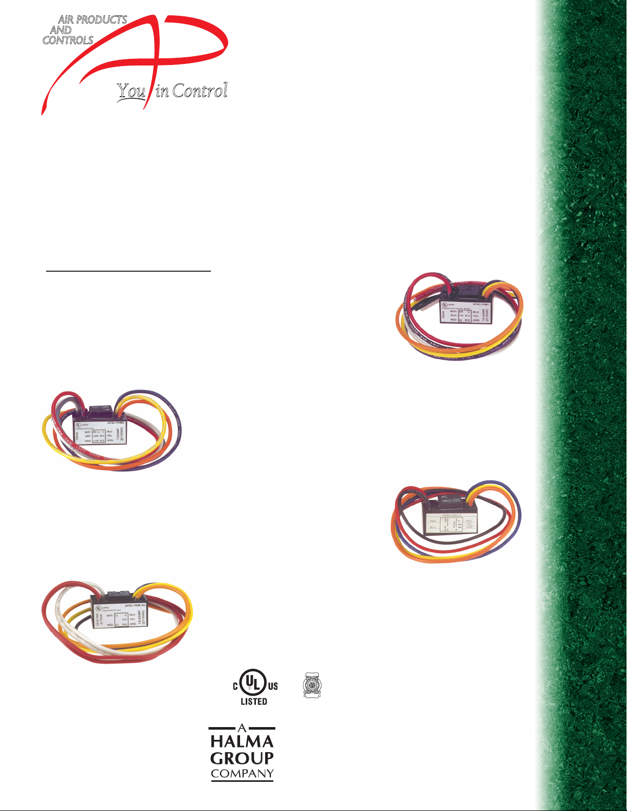
PAM-2
The PAM-2 Relay provides 7.0 A form “C” contacts. The relay may be energized
by one of two input voltages: 12VDC or 24VDC. The input voltages are
polarity-sensitive and diode-protected. PAM-2 Relays contain a red LED which
indicates when the relay coil is energized.
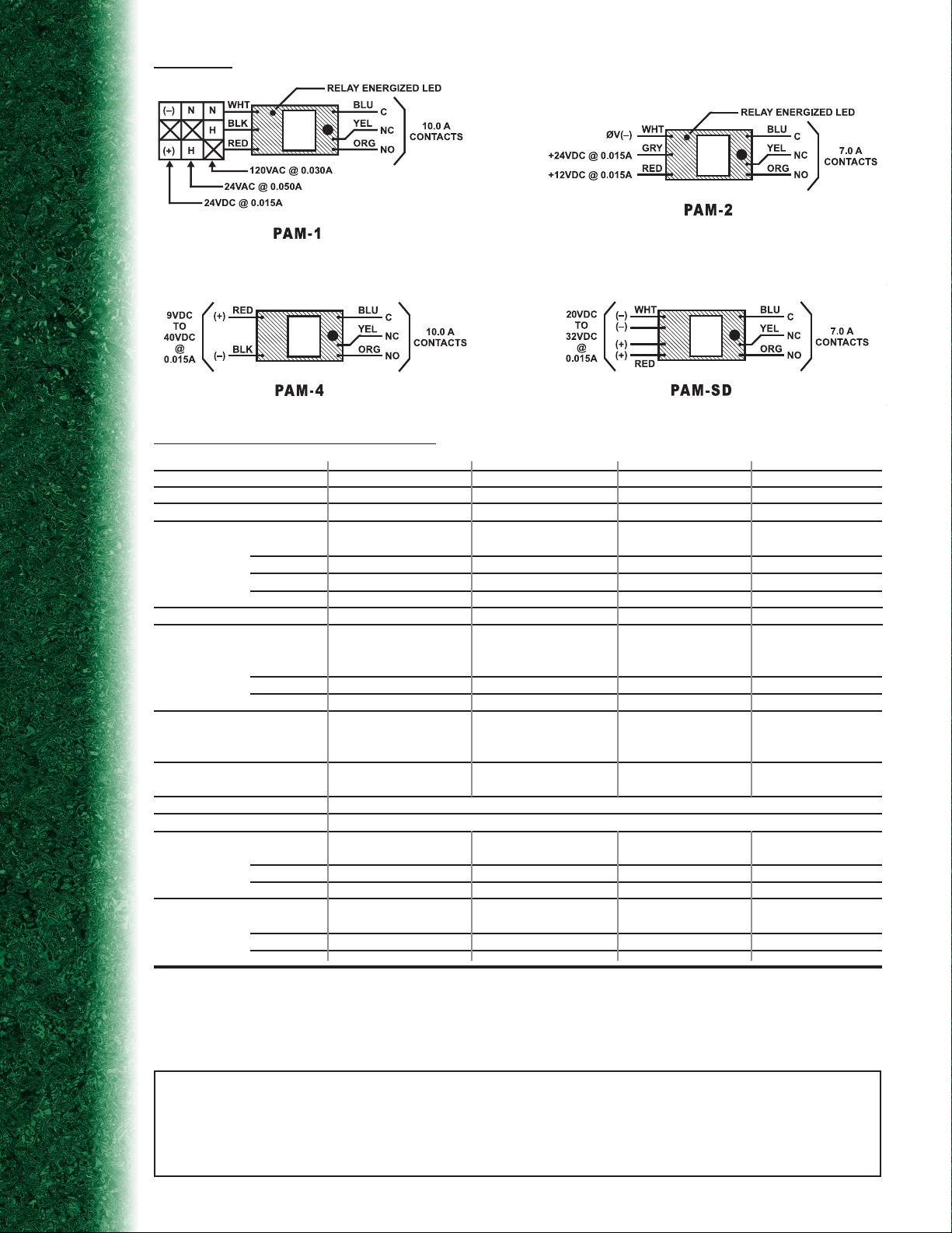
PAM-4
The PAM-4 Relay provides 10.0 A form “C” contacts. The relay may be energized
across a wide voltage range from 9VDC to 40VDC, making it ideal for 12VDC
and 24VDC EOL circuits. The 15mA operating current is constant across the
operating range. The input voltages are polarity-sensitive and diode-protected.
PAM-SD
The PAM-SD Relay provides 7.0 A form “C” contacts. The relay may be
energized by an input voltage between 20VDC to 32VDC, making it ideal
for 24VDC NAC circuits. The input voltages are polarity-sensitive and diodeprotected. The PAM-SD provides an additional set of wires for redundant
input voltage (circuit supervision pass through).
CSFM LISTED
MEA ACCEPTED
Page 2
WIRING
PRODUCT SPECIFICATIONS
MODEL NUMBER: PAM-1 PAM-2 PAM-4 PAM-SD
COIL VOLTAGE: 24VAC/24VDC/120VAC 12VDC/24VDC 9 to 40VDC 20 to 32VDC
POLARIZED:
ENERGIZED LED INDICATOR: Yes Yes No No
CURRENT REQUIREMENT:
@12VDC 15mA
@24VDC 15mA 15mA 15mA 15mA
@24VAC 50mA
@120VAC 30mA
CONTACT CONFIGURATION: (1) SPDT dry form “C” (1) SPDT dry form “C” (1) SPDT dry form “C” (1) SPDT dry form “C”
CONTACT RATINGS:
(contact rating/ power factor)
@5VDC
@24VDC 7A / .35 PF 7A / .35 PF 7A 7A / .35 PF
@120VAC 10A 7A / .35 PF 10A 7A / .35 PF
WIRE LEADS: 6 “flying” leads 6 “flying” leads 5 “flying” leads 7 “flying” leads
AMBIENT TEMPERATURE: 32°F to 120°F 32°F to 120°F 32°F to 120°F 32°F to 120°F
(@ 100% RH, condensing) (0°C to 49°C) (0°C to 49°C) (0°C to 49°C) (0°C to 49°C)
CONSTRUCTION: 100% potted (sealed) with “flying” leads
MOUNTING: Pre-drilled mounting screw hole and self tapping screw provided. Double sided tape provided.
DIMENSIONS:
H 1.50” (38mm) 1.50” (38mm) 1.50” (38mm) 1.50” (38mm)
W 1.20” (25mm) 1.00” (25mm) 1.00” (25mm) 1.00” (25mm)
D 0.90” (20mm) 0.90” (23mm) 0.90” (23mm) 0.80” (20mm)
LISTINGS AND APPROVALS:
UL*: U0XX/7.S3403 U0XX/7.S3403 U0XX/7.S3403 U0XX/7.S3403
MEA: 73-92-E Vol. 21 73-92-E Vol. 21 73-92-E Vol. 21 73-92-E Vol. 21
CSFM: 7300-1004:101 7300-1004:101 7300-1004:101 7300-1004:101
*UOXX=Control Unit Accessories, System; /7=also Certified for Canada
Yes Yes Yes Yes
15mA
250µA / .35 PF 250µA / .35 PF 250µA 250µA / .35 PF
12” / 18 AWG 12” / 18 AWG 12” / 18 AWG 12” / 18 AWG
Wire-nuts provided Wire-nuts provided Wire-nuts provided Wire-nuts provided
NOTICE:
The information contained in this document is intended only as a summary and is subject to change without notice. The products described have specific
instructional/installation documentation, which covers various technical, approval, code, limitation and liability information. Copies of this documentation along with any general product warning and limit ation documents, which also c ontain imp ortant information, are provi ded with the product and are also avail able from Air Products and
Controls I nc. The information contained in all of these documents should be considered before specifying or using the products. Any example applications shown are
subject to the most current enforced local/national codes, standards, approvals, c ertifications, and/or the a uthority havi ng jurisdicti on. All of t hese resource s, as well as
the specific manufacturer of any shown or mentioned related equipment, should be consulted prior to any implementation. For further information or assistance concerning
the products, contact Air Products and Controls Inc. Air Products and Controls Inc. reserves the right to change any and all documentation without notice.
© Air Products and Controls Inc. 2006
DS-RL-1 E060404
 Loading...