

Page 1
Easergy P3
Universal Relays P3U10, P3U20 and P3U30
User Manual
P3U/en M/F005
01/2020
www.schneider-electric.com
Page 2

Page 3

Table of Contents
Table of Contents
1. About this manual....................................................................... 12
1.1. Purpose..........................................................................................................12
1.2. Related documents........................................................................................12
1.3. Abbreviations and terms................................................................................ 13
2. Product introduction.................................................................... 18
2.1. Warranty.........................................................................................................18
2.2. Product overview........................................................................................... 18
2.3. Product selection guide..................................................................................19
2.4. Access to device configuration...................................................................... 27
2.4.1. User accounts......................................................................................27
2.4.2. Logging on via the front panel............................................................. 28
2.4.3. HTTP and FTP logon details............................................................... 28
2.4.4. Password management....................................................................... 29
2.4.5. Changing passwords for administrator and configurator accounts via
PuTTY............................................................................................................29
2.4.6. Password restoring.............................................................................. 31
2.5. Front panel.....................................................................................................32
2.5.1. Push-buttons........................................................................................32
2.5.2. LED indicators..................................................................................... 33
2.5.3. Controlling the alarm screen................................................................34
2.5.4. Accessing operating levels.................................................................. 34
2.5.5. Adjusting the LCD contrast.................................................................. 34
2.5.6. Testing the LEDs and LCD screen.......................................................35
2.5.7. Controlling an object with selective control..........................................35
2.5.8. Controlling an object with direct control............................................... 35
2.5.9. Menus..................................................................................................35
2.6. Easergy Pro setting and configuration tool.................................................... 38
Universal Relays P3U10, P3U20 and P3U30
2.5.9.1. Moving in the menus ............................................................. 37
2.5.9.2. Local panel messages............................................................38
3. Measurement functions...............................................................40
3.1. Primary, secondary and per unit scaling........................................................ 42
3.1.1. Frequency adaptation mode................................................................ 44
3.1.2. Current transformer ratio..................................................................... 45
3.1.3. Voltage transformer ratio..................................................................... 47
3.2. Measurements for protection functions..........................................................49
3.3. RMS values....................................................................................................50
3.4. Harmonics and total harmonic distortion (THD).............................................50
3.5. Demand values..............................................................................................51
3.6. Minimum and maximum values..................................................................... 53
3.7. Maximum values of the last 31 days and 12 months..................................... 54
3.8. Power and current direction........................................................................... 56
3.9. Symmetrical components...............................................................................57
P3U/en M/F005 3
Page 4

Universal Relays P3U10, P3U20 and P3U30
4. Control functions......................................................................... 59
4.1. Digital outputs................................................................................................ 59
4.2. Digital inputs.................................................................................................. 61
4.3. Virtual inputs and outputs...............................................................................63
4.4. Matrix............................................................................................................. 66
4.4.1. Output matrix....................................................................................... 66
4.4.2. Blocking matrix.................................................................................... 67
4.4.3. Object block matrix.............................................................................. 68
4.4.4. Auto-recloser matrix.............................................................................69
4.5. Releasing latches...........................................................................................69
4.5.1. Releasing latches using Easergy Pro.................................................. 69
4.5.2. Releasing latches using buttons and local panel display.....................69
4.5.3. Releasing latches using F1 or F2 buttons........................................... 70
4.6. Controllable objects....................................................................................... 70
4.6.1. Object control with digital inputs.......................................................... 72
4.6.2. Local or remote selection.....................................................................72
4.6.3. Object control with Close and Trip buttons.......................................... 73
4.6.4. Object control with F1 and F2..............................................................73
4.7. Logic functions...............................................................................................74
4.8. Local panel.....................................................................................................82
4.8.1. Mimic view........................................................................................... 83
4.8.2. Local panel configuration.....................................................................85
Table of Contents
5. Protection functions.....................................................................90
5.1. Maximum number of protection stages in one application.............................90
5.2. General features of protection stages............................................................90
5.3. Application modes..........................................................................................98
5.4. Current protection function dependencies..................................................... 98
5.5. Dependent operate time................................................................................ 98
5.5.1. Standard dependent delays using IEC, IEEE, IEEE2 and RI curves.100
5.5.2. Custom curves................................................................................... 114
5.5.3. Programmable dependent time curves.............................................. 115
5.6. Synchronism check (ANSI 25)..................................................................... 116
5.7. Undervoltage (ANSI 27)...............................................................................120
5.8. Directional power (ANSI 32) ....................................................................... 123
5.9. Phase undercurrent (ANSI 37).....................................................................125
5.10. Broken conductor (ANSI 46BC) ................................................................ 126
5.11. Negative sequence overcurrent (ANSI 46) ................................................127
5.12. Incorrect phase sequence (ANSI 46) ........................................................129
5.13. Negative sequence overvoltage protection (ANSI 47)............................... 130
5.14. Motor start-up supervision (ANSI 48) ........................................................131
5.15. Thermal overload (ANSI 49 RMS)............................................................. 136
5.16. Breaker failure 1 (ANSI 50BF)................................................................... 140
5.17. Breaker failure 2 (ANSI 50BF)................................................................... 141
5.18. Switch-on-to-fault (ANSI 50HS) ................................................................ 147
5.19. Phase overcurrent (ANSI 50/51)................................................................149
4 P3U/en M/F005
Page 5

Table of Contents
Universal Relays P3U10, P3U20 and P3U30
5.20. Ground fault overcurrent (ANSI 50N/51N) ................................................ 153
5.20.1. Ground fault phase detection...........................................................157
5.21. Capacitor bank unbalance (ANSI 51C) .....................................................158
5.22. Locked rotor (ANSI 51LR)..........................................................................164
5.23. Voltage-dependent overcurrent (ANSI 51V) ............................................. 166
5.24. Overvoltage (ANSI 59)...............................................................................168
5.25. Capacitor overvoltage (ANSI 59C) ............................................................171
5.26. Neutral overvoltage (ANSI 59N)................................................................ 176
5.27. Motor restart inhibition (ANSI 66) ..............................................................178
5.28. Directional phase overcurrent (ANSI 67) .................................................. 181
5.29. Directional ground fault overcurrent (ANSI 67N)....................................... 185
5.29.1. Ground fault phase detection...........................................................191
5.30. Transient intermittent ground fault (ANSI 67NI).........................................192
5.31. Second harmonic inrush detection (ANSI 68F2)........................................197
5.32. Fifth harmonic detection (ANSI 68H5)....................................................... 198
5.33. Auto-recloser function (ANSI 79) .............................................................. 199
5.34. Overfrequency and underfrequency (ANSI 81) .........................................204
5.35. Rate of change of frequency (ANSI 81R).................................................. 206
5.36. Lockout (ANSI 86)......................................................................................211
5.37. Programmable stages (ANSI 99)............................................................... 212
6. Supporting functions................................................................. 215
6.1. Event log......................................................................................................215
6.2. Disturbance recording..................................................................................217
6.3. Cold load start and magnetizing inrush........................................................223
6.4. System clock and synchronization...............................................................224
6.5. Voltage sags and swells...............................................................................230
6.6. Voltage interruptions....................................................................................232
6.7. Current transformer supervision (ANSI 60) .................................................234
6.8. Voltage transformer supervision (ANSI 60FL)............................................. 236
6.9. Circuit breaker wear.....................................................................................237
6.10. Circuit breaker condition monitoring.......................................................... 243
6.11. Energy pulse outputs..................................................................................245
6.12. Running hour counter................................................................................ 249
6.13. Timers........................................................................................................250
6.14. Combined overcurrent status.....................................................................252
6.15. Main short-circuit fault locator.................................................................... 254
6.16. Feeder fault locator (ANSI 21FL)............................................................... 259
6.17. Trip circuit supervision (ANSI 74) ..............................................................263
6.17.1. Trip circuit supervision with one digital input....................................263
6.17.2. Trip circuit supervision with two digital inputs.................................. 269
7. Communication and protocols...................................................273
7.1. Cybersecurity...............................................................................................273
7.2. Communication ports...................................................................................273
7.2.1. Remote and extension ports..............................................................274
P3U/en M/F005 5
Page 6

Universal Relays P3U10, P3U20 and P3U30
7.2.2. Ethernet port......................................................................................274
7.2.3. Disabling the Ethernet communication.............................................. 274
7.3. Communication protocols............................................................................ 275
7.3.1. Modbus RTU and Modbus TCP.........................................................276
7.3.2. Profibus DP........................................................................................276
7.3.3. SPA-bus.............................................................................................277
7.3.4. IEC 60870-5-103 (IEC-103)...............................................................277
7.3.5. DNP 3.0............................................................................................. 278
7.3.6. IEC 60870-5-101 (IEC-101)...............................................................278
7.3.7. IEC 61850..........................................................................................279
7.3.8. HTTP server – Webset...................................................................... 279
7.4. IP filter..........................................................................................................279
7.4.1. Configuring the IP filter...................................................................... 280
7.4.2. Unexpected packets.......................................................................... 282
7.4.3. Alarms................................................................................................282
8. Applications and configuration examples..................................284
Table of Contents
8.1. Substation feeder protection........................................................................284
8.2. Industrial feeder / motor protection.............................................................. 286
8.3. Using CSH120 and CSH200 with core balance CTs................................... 286
9. Installation................................................................................. 289
9.1. Safety in installation.....................................................................................289
9.2. Checking the consignment...........................................................................290
9.3. Product identification....................................................................................291
9.4. Storage........................................................................................................ 292
9.5. Mounting...................................................................................................... 293
9.6. Connections.................................................................................................296
9.6.1. Rear panel......................................................................................... 297
9.6.2. Auxiliary voltage.................................................................................309
9.6.3. Local port...........................................................................................309
9.6.4. Connection data.................................................................................310
9.6.5. External option modules.................................................................... 316
9.6.5.1. VSE-001 fiber optic interface module...................................316
9.6.5.2. VSE-002 RS-485 interface module...................................... 317
9.6.5.3. VSE-009 DeviceNet interface module..................................319
9.6.5.4. VPA-3CG Profibus interface module.................................... 320
9.6.5.5. VIO 12A RTD and analog input / output modules................ 321
9.6.6. Block diagrams.................................................................................. 322
9.6.7. Connection examples........................................................................ 329
9.7. Voltage system configuration.......................................................................339
9.8. CSH120 and CSH200 Core balance CTs.................................................... 346
10. Test and environmental conditions..........................................350
10.1. Disturbance tests....................................................................................... 350
10.2. Electrical safety tests................................................................................. 351
10.3. Mechanical tests........................................................................................ 352
10.4. Environmental tests................................................................................... 352
6 P3U/en M/F005
Page 7

Table of Contents Universal Relays P3U10, P3U20 and P3U30
10.5. Environmental conditions...........................................................................353
10.6. Casing........................................................................................................353
11. Maintenance............................................................................ 354
11.1. Preventive maintenance.............................................................................354
11.2. Periodic testing...........................................................................................355
11.3. Hardware cleaning..................................................................................... 355
11.4. System status messages........................................................................... 355
11.5. Spare parts.................................................................................................355
11.6. Self-supervision..........................................................................................355
11.6.1. Diagnostics.......................................................................................356
12. Order codes and accessories................................................. 358
12.1. Order codes............................................................................................... 358
12.2. Accessories................................................................................................360
13. Firmware revision....................................................................362
P3U/en M/F005 7
Page 8

Universal Relays P3U10, P3U20 and P3U30 Legal information
Legal information
The Schneider Electric brand and any registered trademarks of Schneider Electric
Industries SAS referred to in this guide are the sole property of Schneider Electric
SA and its subsidiaries. They may not be used for any purpose without the
owner's permission, given in writing. This guide and its content are protected,
within the meaning of the French intellectual property code (Code de la propriété
intellectuelle français, referred to hereafter as "the Code"), under the laws of
copyright covering texts, drawings and models, as well as by trademark law. You
agree not to reproduce, other than for your own personal, noncommercial use as
defined in the Code, all or part of this guide on any medium whatsoever without
Schneider Electric's permission, given in writing. You also agree not to establish
any hypertext links to this guide or its content. Schneider Electric does not grant
any right or license for the personal and noncommercial use of the guide or its
content, except for a non-exclusive license to consult it on an "as is" basis, at your
own risk. All other rights are reserved.
Electrical equipment should be installed, operated, serviced and maintained only
by qualified personnel. No responsibility is assumed by Schneider Electric for any
consequences arising out of the use of this material.
As standards, specifications and designs change from time to time, please ask for
confirmation of the information given in this publication.
8 P3U/en M/F005
Page 9

Safety information
Safety information
Important information
Read these instructions carefully and look at the equipment to become familiar
with the device before trying to install, operate, service or maintain it.
The following special messages may appear throughout this publication or on the
equipment to warn of potential hazards or to call attention to information that
clarifies or simplifies a procedure.
Universal Relays P3U10, P3U20 and P3U30
This is the safety alert symbol. It is used to alert you to potential
personal injury hazards. Obey all safety messages that follow this
symbol to avoid possible injury or death.
The addition of either symbol to a “Danger” or “Warning” safety
label indicates that an electrical hazard exists which will result in
personal injury if the instructions are not followed.
DANGER
DANGER indicates a hazardous situation which, if not avoided, will result
in death or serious injury.
WARNING
WARNING indicates a hazardous situation which, if not avoided, could
result in death or serious injury.
CAUTION
CAUTION indicates a hazardous situation which, if not avoided, could
result in minor or moderate injury.
NOTICE
NOTICE is used to address practices not related to physical injury.
Please note
Electrical equipment must only be installed, operated, serviced, and maintained
by qualified personnel. A qualified person is one who has skills and knowledge
related to the construction, installation, and operation of electrical equipment and
has received safety training to recognize and avoid the hazards involved.
No responsibility is assumed by Schneider Electric for any consequences arising
out of the use of this material.
Protective grounding
The user is responsible for compliance with all the existing international and
national electrical codes concerning protective grounding of any device.
P3U/en M/F005 9
Page 10

Universal Relays P3U10, P3U20 and P3U30 North America regulatory compliance
North America regulatory compliance
Certificate number: 20190829-E215590
Issue date: 2019-August-29
UL certifies that the Easergy P3 products comply with the following standards:
• UL 508 Industrial Control Equipment
• CSA C22.2 No. 14-13 Industrial Control Equipment
• IEEE C37.90-2005 Guide for Power System Protection Testing
• IEEE C37.90.1-2012 Standard for Surge Withstand Capability (SWC) Tests
for Relays and Relay Systems Associated with Electrical Power Apparatus
• IEEE C37.90.2-2004 Standard for Withstand Capability of Relay Systems to
Radiated Electromagnetic Interference from Trancievers
10 P3U/en M/F005
Page 11

EU directive compliance Universal Relays P3U10, P3U20 and P3U30
EU directive compliance
EMC compliance
2014/30/EU
Compliance with the European Commission's EMC Directive. Product Specific
Standard was used to establish conformity:
• EN 60255-26 2013
Product safety
2014/35/EU
Compliance with the European Commission's Low Voltage Directive. Product
Specific Safety Standard was used to establish conformity:
• EN 60255-27 2014
P3U/en M/F005 11
Page 12

Universal Relays P3U10, P3U20 and P3U30 1. About this manual
1. About this manual
1.1. Purpose
This document contains instructions on the installation, commissioning and
operation of Easergy P3U10, P3U20 and P3U30.
This document is intended for persons who are experts on electrical power
engineering, and it covers the relay models as described by the order code.
Related topics
Order codes on page 358
1.2. Related documents
Table 1 - Related documents
Document
Easergy P3 Universal Relay P3U Quick Start P3U/EN QS/xxxx
Easergy Pro Setting and Configuration Tool User Manual P3eSetup/EN M/xxxx
RTD and mA Output/Input Modules User Manual P3VIO12A/EN M/A001
Profibus Interface Module User Manual P3VPA3CG/EN M/A001
IEC 61850 configuration instructions P3APS17001EN
Rapid Spanning Tree Protocol (RSTP) P3APS17002EN
Parallel Redundancy Protocol for Easergy P3 relays with dualport 100 Mbps Ethernet interface
Communication parameter protocol mappings P3TDS17005EN
Easergy P3 protection functions' parameters and recorded
values
DeviceNet data model P3APS17008EN
Identification
P3APS17004EN
P3TDS17006EN
1
IEC103 Interoperability List P3TDS17009EN
DNP 3.0 Device Profile Document P3TDS17010EN
P3 Standard Series facia label instruction P3TDS17011EN
Principles of numerical protection techniques P3INS17019EN
1
xxxx = revision number
12 P3U/en M/F005
Page 13

1. About this manual Universal Relays P3U10, P3U20 and P3U30
1.3. Abbreviations and terms
AFD Arc flash detection
ANSI American National Standards Institute
A standardization organisation
bps Bits per second
CB Circuit breaker
CBFP Circuit breaker failure protection
CLPU Cold load pickup
CM Common mode
Controlling output Heavy duty output rated for the circuit breaker controlling
CPU Central processing unit
cosφ Active power divided by apparent power = P/S
(See power factor PF.)
Negative sign indicates reverse power.
CT Current transformer
CT
PRI
CT
SEC
Dead band See hysteresis.
DI Digital input
Digital output Relay's output contact
DM Differential mode
DMS Distribution management system
Nominal primary value of current transformer
Nominal secondary value of current transformer
DO Digital output
Document file Stores information about the relay settings, events and fault logs
DSR Data set ready
An RS232 signal. Input in front panel port of Easergy P3 devices
to disable rear panel local port.
DST Daylight saving time
Adjusting the official local time forward by one hour for summer
time.
DT Definite time
P3U/en M/F005 13
Page 14

Universal Relays P3U10, P3U20 and P3U30 1. About this manual
DTR Data terminal ready
An RS232 signal. Output and always true (+8 Vdc) in front panel
port of Easergy P3 relays.
Easergy P3 Standard P3U10, P3U20 and P3U30 relays
Easergy P3
P3F30, P3L30, P3M30/32, P3G30/32 and P3T32 relays
Advanced
eSetup Easergy Pro Setting and configuration tool for Easergy P3 protection relays,
later called Easergy Pro
F2BIO 2 x optical BIO interfaces, fibre
GOOSE Generic object-oriented substation event
A specific definition of a type of generic substation event, for
peer-peer communication.
Hysteresis I.e. dead band
Used to avoid oscillation when comparing two nearby values.
IDMT Inverse definite minimum time
I
MODE
Nominal current of the selected mode
In feeder mode, I
In motor mode, I
MODE
MODE
= CT
= I
MOT
PRIMARY
.
.
I
MOT
I
NOM
Nominal current of the protected motor
Nominal current
Rating of CT primary or secondary
I
SET
I
N(nom)
I
0 SET
Start setting value I> (50/51)
Nominal current of IN input in general
Start setting value I0>
IEC International Electrotechnical Commission
An international standardization organisation
IEC-101 Communication protocol defined in standard IEC 60870-5-101
IEC-103 Communication protocol defined in standard IEC 60870-5-103
IEEE Institute of Electrical and Electronics Engineers
IRIG-B Inter-Range Instrumentation Group time code B
Standard for time transfer
IT Instrument transformer (current or voltage transformer): electrical
device used to isolate or transform voltage or current levels
14 P3U/en M/F005
Page 15

1. About this manual Universal Relays P3U10, P3U20 and P3U30
LAN Local area network
Ethernet-based network for computers and devices
Latching Digital outputs and indication LEDs can be latched, which means
that they are not released when the control signal is releasing.
Releasing of latched devices is done with a separate action.
LCD Liquid crystal display
LED Light-emitting diode
NTP Network Time Protocol for LAN and WWW
OVF Indication of the event overflow
P Active power
Unit = [W]
PF Power factor
The absolute value is equal to cosφ, but the sign is 'IND' for
inductive i.e. lagging current and 'CAP' for capacitive i.e. leading
current.
PLC Programmable logic controller
P
M
Nominal power of the prime mover
(Used by reverse/under power protection.)
POC signals
Binary signals that are transferred in the communication channel
of two P3L30 line differential relays in both directions. POC
signals are used to transfer statuses of the DI, VI, VO and logic
outputs.
pu
PU
Per unit
Depending of the context, the per unit refers to any nominal
value.
For example, for overcurrent setting 1 pu = 1 x I N .For example,
for overcurrent setting 1 pu = 1 x I
MOT
.
P3U P3U10, P3U20 and P3U30 protection relay
Q Reactive power
Unit = [var]
RELxxxxx Short order code
RH Relative humidity
RMS Root mean square
RS232 or RS485
(EIA-232 or EIA-485)
Standard defining the electrical characteristics of a serial
communication interface
P3U/en M/F005 15
Page 16

Universal Relays P3U10, P3U20 and P3U30 1. About this manual
RTU Remote terminal unit
S Apparent power
Unit = [VA]
SCADA Supervisory control and data acquisition
SF Alarm duty watchdog output is energized when the auxiliary
power supply is on and the product status is operative. This
output is referenced as "service status output" in the setting tool.
Signaling output Alarm duty output rated, not suitable for direct circuit breaker
controlling
SNTP Simple Network Time Protocol for LAN and WWW
SOTF Switch on to fault
SPST Single pole single throw
SPDT Single pole double throw
TCS Trip circuit supervision
THD Total harmonic distortion
V Voltage V
V
NSEC
Voltage at input Vc at zero ohm ground fault. (Used in voltage
measurement mode “2LL+VN”)
V
A
Voltage input for VAB or VA depending on the voltage
measurement mode
V
B
Voltage input for VBC or VB depending on the voltage
measurement mode
V
C
Voltage input for VCA or VN depending on the voltage
measurement mode
V
N
Neutral voltage
Rating of VT primary or secondary
V
NOM
Nominal voltage
Rating of VT primary or secondary
UMI User-machine interface
USB Universal serial bus
UTC Coordinated Universal Time
Used to be called GMT = Greenwich Mean Time
Webset http configuration interface
16 P3U/en M/F005
Page 17

1. About this manual Universal Relays P3U10, P3U20 and P3U30
VI Virtual input
VO Virtual output
VT Voltage transformer
VT
VT
PRI
SEC
Nominal primary value of voltage transformer
Nominal secondary value of voltage transformer
Parameter names in user manual and Easergy Pro
Some parameters may have a different name in this user manual compared to the
Easergy Pro setting tool.
Table 2 - Parameter names in user manual and Easergy Pro
User manual Easergy Pro
Base angle setting range Angle offset
Characteristic curve / curve type Delay type
Cooling time coefficient Rel. cooling time coefficient
Dependent time coefficient Inv. time coefficient
Operate angle Pick-up sector size
Operate time Operation delay
Self-blocking value of undervoltage Low voltage blocking
Start value Pick-up setting
Start voltage
Time multiplier Inv. time coefficient / Inverse delay
3BIO 3 x hard-wired BIO interfaces
VN setting for INDir stage > (67N)
P3U/en M/F005 17
Page 18

Universal Relays P3U10, P3U20 and P3U30
2. Product introduction
2.1. Warranty
This product has a standard warranty of 10 years.
2.2. Product overview
The relay communicates with other systems using common protocols, such as the
Modbus RTU, ModbusTCP, IEC 60870-5-103, IEC 60870-5-101, IEC 61850, SPA
bus, and DNP 3.0.
User interface
The relay can be controlled in three ways:
2. Product introduction
• Locally with the push-buttons on the relay front panel
• Locally using a PC connected to the USB port on the front
• Via remote control over the optional remote control port on the relay rear
panel.
Easergy P3U10, P3U20 and P3U30 include all the essential protection functions
needed to protect feeders and motors in distribution networks of utilities, industry
and power plants for all level of voltage below 132 kV. Further, the relay includes
several programmable functions, such as trip circuit supervision and circuit
breaker protection and communication protocols for various protection and
communication situations.
Protection functions
• Universal, adaptive protection functions for user-configurable applications like
feeder, motor and voltage protection from basic non-directional to directional
overcurrent protection, thermal overload, and auto-recloser
• Neutral overvoltage, overvoltage and frequency protection including
synchronism check for two breakers
• Single-line diagram, measurements and alarms in the user-machine interface
(UMI)
• User-configurable interlocking for primary object control
• Optional arc flash detection utilizing point sensors and a fiber loop that can
provide system wide arc flash detection.
Virtual injection
• Current and voltage injection by manipulating the database of the product by
setting tool disturbance recorder file playback through the product's database
Robust hardware
• User-selectable Ethernet, RS485 or RS232 -based communication interfaces
• Designed for demanding industrial conditions with conformal-coated printed
circuit boards
• Standard USB connection (type B) for Easergy P3 setting software
18 P3U/en M/F005
Page 19
1
4
3
2. Product introduction Universal Relays P3U10, P3U20 and P3U30
Common technology for cost efficiency
• Powerful CPU supporting IEC 61850
• Thanks to four setting groups, adaptation to various protection schemes is
convenient
User-machine interface (UMI)
• Clear LCD display for alarms and events
• Single-line diagram mimic with control, indication and live measurements
• Programmable function keys and LEDs
• Circuit breaker ON/OFF control
• Common firmware platform with other Easergy P3 range protection relays
NOTE: If the device has been powered off for more than about one week, the
UMI language after starting is IEC but after about two minutes, it is
automatically updated to ANSI.
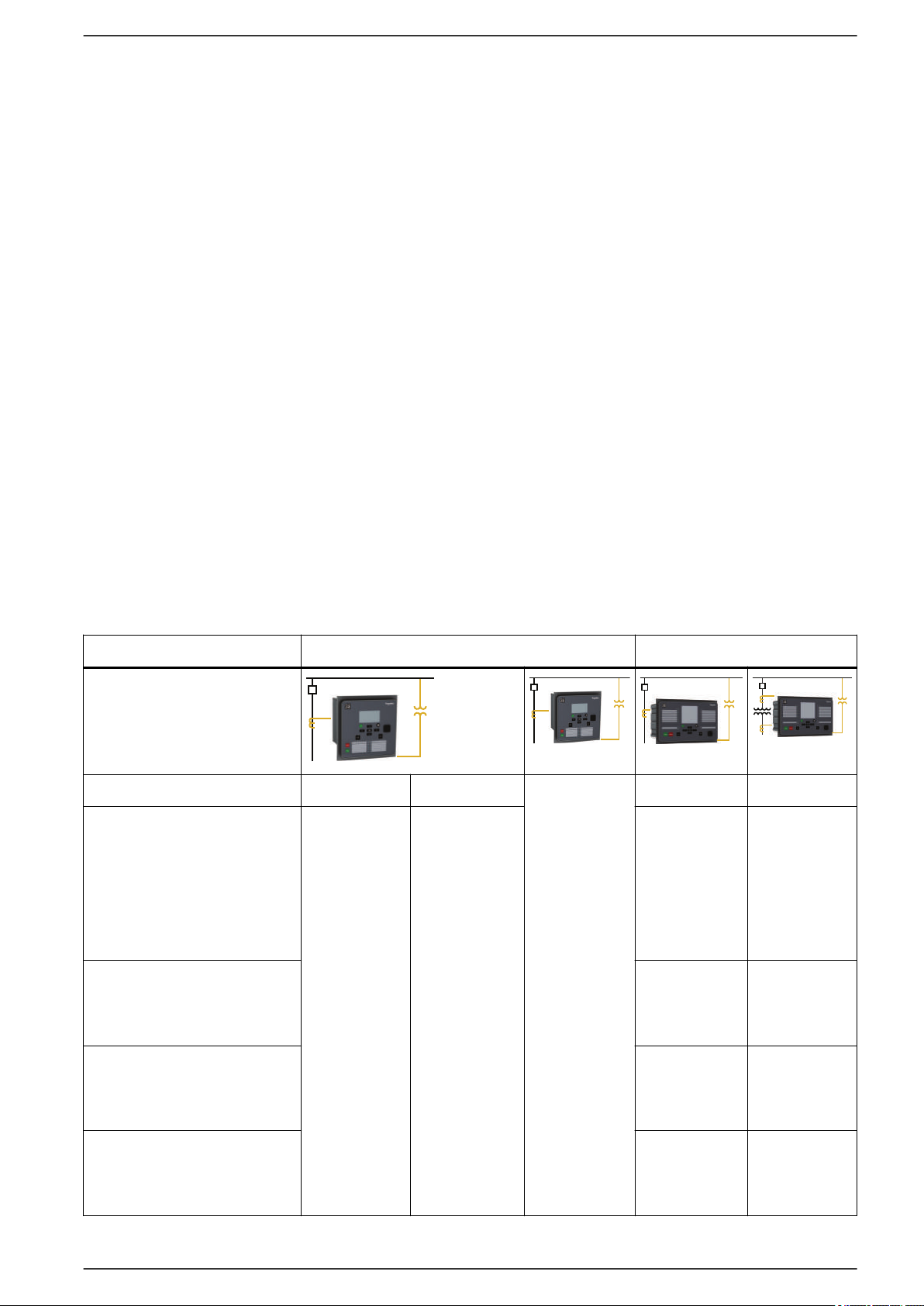
2.3. Product selection guide
The selection guide provides information on the Easergy P3 platform to aid in the
relay selection. It suggests Easergy P3 types suitable for your protection
requirements, based on your application characteristics. The most typical
applications are presented along with the associated Easergy P3 type.
Table 3 - Applications
Easergy P3 Standard Easergy P3 Advanced
Voltage – –
Feeder
Transformer
P3U10 P3U20
Motor
P3U30
with
directional
o/c
with voltage
protection
P3F30
w.
directional
P3L30
w. line diff. &
distance
–
P3M30
–
–
P3T32
with
differential
P3M32
with
differential
Generator
P3G30
P3U/en M/F005 19
P3G32
with
differential
Page 20
1
4
3
Universal Relays P3U10, P3U20 and P3U30 2. Product introduction
Easergy P3 Standard Easergy P3 Advanced
Measuring
inputs
Phase current 1/5A CT (x3) 1/5A CT (x3) 1/5A CT (x6)
Residual current 1/5A CT or 0.2/1A CT 5/1A+1/0.2A 5/1A+1/0.2A +
5/1A CT
Voltage VT (x1) VT (x4) VT (x4) VT (x4)
Arc-flash sensor input – 0 to 4 point
sensor
0 to 4 point
sensor
Digital I/O Input 2 8/10 16 6 to 36 6 to 16
Output 5 + WD 5/8 + WD 8 + WD 10 to 21 + WD 10 to 13 + WD
Analog I/O Input –
Output –
Temperature sensor input –
2
0 or 4
2
0 or 4
0 or 8 or 12
2
0 or 8 or 12
0 or 4
0 or 4
2
2
2
Front port USB USB
Nominal power supply
24 V dc or 24...48 V dc or 48...230 V ac/dc
3
24...48 V dc or 110...240 V ac/dc
Ambient temperature, in service -40...60°C (-40...140°F) -40...60°C (-40...140°F)
2
Using external RTD module
3
Check the available power supply range from the device's serial number label.
Table 4 - Communication & others
Easergy P3 Standard Easergy P3 Advanced
Communication
Rear ports RS-232 – ■ ■ ■
IRIG/B ■ ■ ■
RS-485 – ■ Using external
ETHERNET – ■ ■ ■
Protocols IEC 61850 Ed1
& Ed2
IEC 60870-5-101 – ■ ■ ■ ■
IEC 60870-5-103 – ■ ■ ■ ■
I/O module
– ■ ■ ■ ■
Using external
I/O module
DNP3 Over
– ■ ■ ■ ■
Ethernet
Modbus serial – ■ ■ ■ ■
Modbus TCP/IP – ■ ■ ■ ■
DeviceNet – ■ ■ ■ ■
Profibus DP – ■ ■ ■ ■
20 P3U/en M/F005
Page 21

2. Product introduction Universal Relays P3U10, P3U20 and P3U30
Easergy P3 Standard Easergy P3 Advanced
SPAbus – ■ ■ ■ ■
Redundancy
protocols
Others
Control
Logic Matrix ■ ■
Cyber security Password Password
Withdrawability (Pluggable
connector)
Remote UMI – ■
RSTP – ■ ■ ■ ■
PRP – ■ ■ ■ ■
1 object
Mimic
Logic equations ■ ■
8 objects
Mimic
■ –
8 objects
Mimic
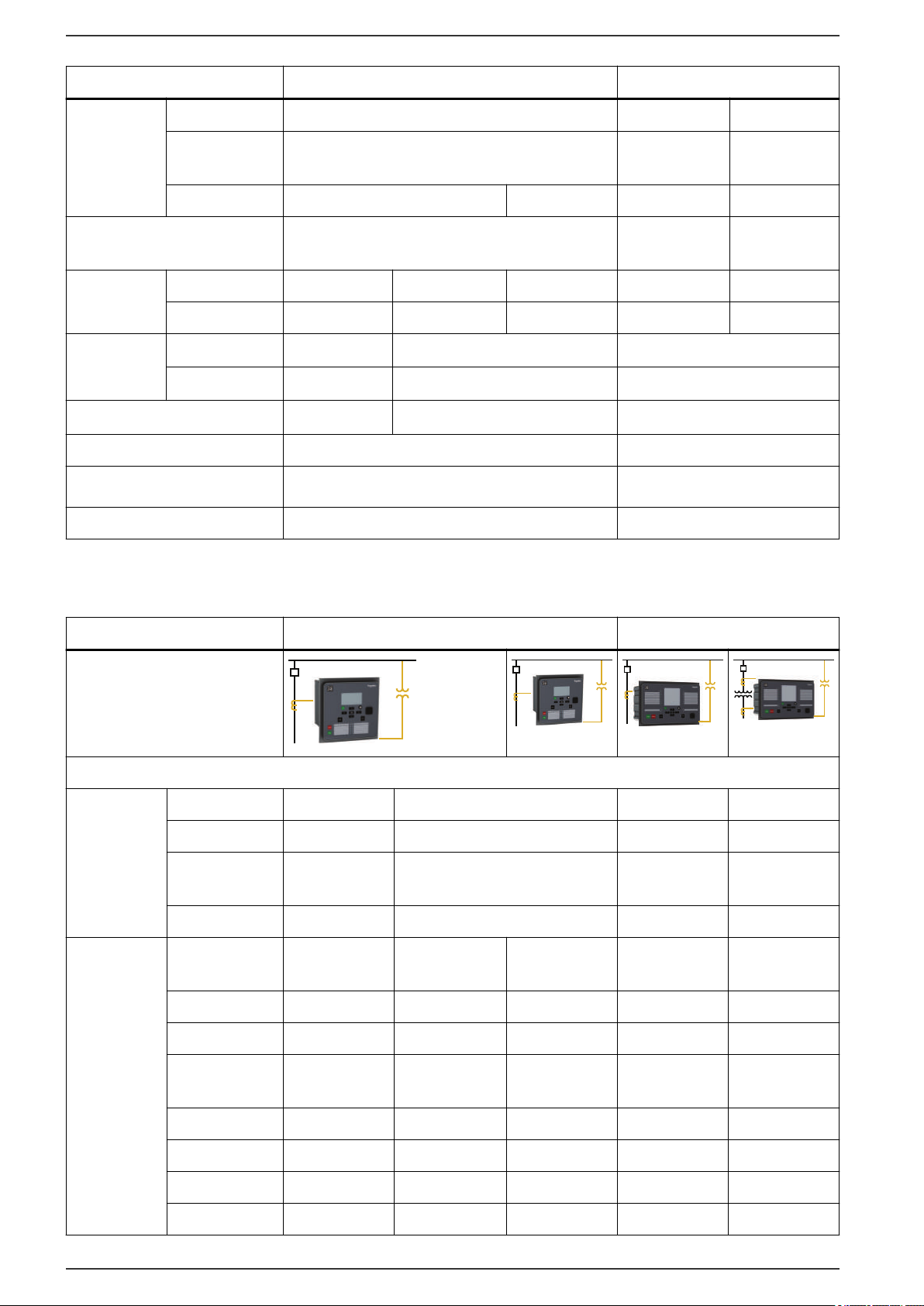
NOTE: The numbers in the following tables represent the amount of stages
available for each Easergy P3 type.
Table 5 - Protection functions for P3U
Protection functions ANSI
code
Feeder
P3U10/20
Feeder P3U30 Motor P3U10/20 Motor P3U30
Fault locator 21FL – 1 – 1
Synchronism check
Undervoltage 27 – 3 – 3
Directional power 32 – 2 – 2
Phase undercurrent 37 1 1 1 1
RTD temperature
monitoring
Negative sequence
overcurrent (motor,
generator)
Incorrect phase sequence 46 – – 1 1
Cur. unbalance, broken
conductor
Negative sequence
overvoltage protection
Excessive start time,
locked rotor
5
4
25 – 2 – 2
38/49T 12 12 12 12
46 – – 2 2
46BC 1 1 – –
47 – 3 – 3
48/51LR – – 1 1
Thermal overload 49 1 1 1 1
Phase overcurrent 50/51 3 3 3 3
Ground fault overcurrent 50N/51N 5 5 5 5
Breaker failure 50BF 1 1 1 1
P3U/en M/F005 21
Page 22

Universal Relays P3U10, P3U20 and P3U30 2. Product introduction
Protection functions ANSI
code
Feeder
P3U10/20
Feeder P3U30 Motor P3U10/20 Motor P3U30
SOTF 50HS 1 1 1 1
Capacitor bank
unbalance
6
Voltage-dependent
51C 2 2 2 2
51V – 1 – 1
overcurrent
Overvoltage 59 – 3 – 3
Capacitor overvoltage 59C 1 1 – –
Neutral overvoltage 59N 3 3 3 3
CT supervision 60 1 1 1 1
VT supervision 60FL – 1 – 1
Starts per hour 66 – – 1 1
Directional phase
67 – 4 – 4
overcurrent
Directional ground fault
67N 3 3 3 3
o/c
Transient intermittent 67NI 1 1 – –
Second harmonic inrush
68F2 1 1 1 1
detection
Fifth harmonic detection 68H5 1 1 1 1
Auto-Recloser 79 5 5 – –
Over or under frequency 81 – 2/2 – 2/2
Rate of change of
81R – 1 – 1
frequency
Under frequency 81U – 2 – 2
Lockout 86 1 1 1 1
Programmable stages 99 8 8 8 8
Cold load pickup (CLPU) – 1 1 1 1
Programmable curves – 3 3 3 3
Setting groups
4
The availability depends on the selected voltage measurement mode (in the Scaling setting view in Easergy Pro)
5
Using external RTD module
6
Capacitor bank unbalance protection is connected to the ground fault overcurrent input and shares two stages with the ground fault
overcurrent protection.
7
Not all protection functions have 4 setting groups. See details in the manual.
7
– 4 4 4 4
Table 6 - Protection functions for Px3x
Protection functions ANSI
P3F30 P3L30 P3M30 P3M32 P3G30 P3G32 P3T32
code
Distance 21 – 1 – – – – –
Under-impedance 21G – – – – 2 2 –
22 P3U/en M/F005
Page 23

2. Product introduction Universal Relays P3U10, P3U20 and P3U30
Protection functions ANSI
P3F30 P3L30 P3M30 P3M32 P3G30 P3G32 P3T32
code
Fault locator 21FL 1 1 – – – – –
Overfluxing 24 – – – – 1 1 1
Synchronism check
8
Undervoltage 27 3 3 3 3 3 3 3
Positive sequence undervoltage
Directional power 32 2 2 2 2 2 2 2
Phase undercurrent 37 – – 1 1 – – –
RTD temperature
monitoring
9
Loss of field 40 – – – – 1 1 –
Under-reactance 21/40 – – – – 2 2 –
Negative sequence
overcurrent (motor,
generator)
25 2 2 2 2 2 2 2
27P – – – – 2 2 –
38/49T 12 12 12 12 12 12 12
46 – – 2 2 2 2 2
Incorrect phase sequence 46 – – 1 1 – – –
Cur. unbalance, broken
46BC 1 1 – – – – –
conductor
Negative sequence
47 3 3 3 3 3 3 3
overvoltage protection
Excessive start time,
48/51LR – – 1 1 – – –
locked rotor
Thermal overload 49 1 1 1 1 1 1 1
Phase overcurrent 50/51 3 3 3 3 3 3 3
Ground fault overcurrent 50N/51N 5 5 5 5 5 5 5
Breaker failure 50BF 1 1 1 1 1 1 1
SOTF 50HS 1 1 1 1 1 1 1
Capacitor bank
unbalance
10
Voltage-dependent
51C 2 2 2 2 2 2 2
51V 1 1 – – 1 1 –
overcurrent
Overvoltage 59 3 3 3 3 3 3 3
Capacitor overvoltage 59C 1 1 – – – – –
Neutral overvoltage 59N 2 2 2 2 2 2 2
CT supervision 60 1 1 1 1 1 2 2
VT supervision 60FL 1 1 1 1 1 1 1
Restricted ground fault
64REF – – – – – 1 1
(low impedance)
P3U/en M/F005 23
Page 24

Universal Relays P3U10, P3U20 and P3U30 2. Product introduction
Protection functions ANSI
P3F30 P3L30 P3M30 P3M32 P3G30 P3G32 P3T32
code
Stator ground fault 64S – – – – 1 1 –
Starts per hour 66 – – 1 1 – – –
Directional phase
overcurrent
Directional ground fault
o/c
Transient intermittent 67NI 1 1 – – – – –
Second harmonic inrush
detection
Fifth harmonic detection 68H5 1 1 1 1 1 1 1
Pole slip 78PS – – – – 1 1 –
Auto-Recloser 79 5 5 – – – – –
Over or under frequency 81 2/2 2/2 2/2 2/2 2/2 2/2 2/2
Rate of change of
frequency
67 4 4 4 4 4 4 4
67N 3 3 3 3 3 3 3
68F2 1 1 1 1 1 1 1
81R 1 1 1 1 1 1 1
Under frequency 81U 2 2 2 2 2 2 2
Lockout 86 1 1 1 1 1 1 1
Line differential 87L – 2 – – – – –
Machine differential 87M – – – 2 – 2 –
Transformer differential 87T – – – – – – 2
Programmable stages 99 8 8 8 8 8 8 8
Arc flash detection (AFD) – 8 8 8 8 8 8 8
Cold load pickup (CLPU) – 1 1 1 1 1 1 1
Programmable curves – 3 3 3 3 3 3 3
Setting groups
8
The availability depends on the selected voltage measurement mode (in the Scaling setting view in Easergy Pro)
9
Using external RTD module
10
Capacitor bank unbalance protection is connected to the ground fault overcurrent input and shares two stages with the ground fault
overcurrent protection.
11
Not all protection functions have 4 setting groups. See details in the manual.
11
– 4 4 4 4 4 4 4
Table 7 - Control functions
Control functions P3U10/20P3U30 P3F30 P3L30 P3M30 P3M32 P3G30 P3G32 P3T32
Switchgear control and
1/2 4 6 6 6 6 6 6 6
monitoring
Switchgear monitoring
– – 2 2 2 2 2 2 2
only
Programmable switchgear
■ ■ ■ ■ ■ ■ ■ ■ ■
interlocking
24 P3U/en M/F005
Page 25

2. Product introduction Universal Relays P3U10, P3U20 and P3U30
Control functions P3U10/20P3U30 P3F30 P3L30 P3M30 P3M32 P3G30 P3G32 P3T32
Local control on single-
■ ■ ■ ■ ■ ■ ■ ■ ■
line diagram
Local control with O/I keys ■ ■ ■ ■ ■ ■ ■ ■ ■
Local/remote function ■ ■ ■ ■ ■ ■ ■ ■ ■
Function keys 2 2 2 2 2 2 2 2 2
Custom logic (logic
■ ■ ■ ■ ■ ■ ■ ■ ■
equations)
Control with Smart App ■ ■ ■ ■ ■ ■ ■ ■ ■
Table 8 - Measurements
Measurement P3U10/20P3U30 P3F30 P3L30 P3M30 P3M32 P3G30 P3G32 P3T32
RMS current values ■ ■ ■ ■ ■
12
■
■
RMS voltage values ■ ■ ■ ■ ■ ■ ■ ■ ■
RMS active, reactive and
– ■ ■ ■ ■ ■ ■ ■ ■
apparent power
12
■
12
■
Frequency ■ ■ ■ ■ ■ ■ ■ ■ ■
Fundamental frequency
■ ■ ■ ■ ■
12
■
■
12
■
■
current values
Fundamental frequency
– ■ ■ ■ ■ ■ ■ ■ ■
voltage values
Fundamental frequency
– ■ ■ ■ ■ ■ ■ ■ ■
active, reactive and
apparent power values
Power factor – ■ ■ ■ ■ ■ ■ ■ ■
Energy values active and
– ■ ■ ■ ■ ■ ■ ■ ■
reactive
Energy transmitted with
– ■ ■ ■ ■ ■ ■ ■ ■
pulse outputs
Demand values: phase
■ ■ ■ ■ ■ ■ ■ ■ ■
currents
Demand values: active,
– ■ ■ ■ ■ ■ ■ ■ ■
reactive, apparent power
and power factor
12
Min and max demand
■ ■ ■ ■ ■ ■ ■ ■ ■
values: phase currents
Min and max demand
■ ■ ■ ■ ■ ■ ■ ■ ■
values: RMS phase
currents
P3U/en M/F005 25
Page 26

Universal Relays P3U10, P3U20 and P3U30 2. Product introduction
Measurement P3U10/20P3U30 P3F30 P3L30 P3M30 P3M32 P3G30 P3G32 P3T32
Min and max demand
values: active, reactive,
apparent power and
power factor
Maximum demand values
over the last 31 days and
12 months: active,
reactive, apparent power
Minimum demand values
over the last 31 days and
12 months: active,
reactive power
Max and min values:
currents
Max and min values:
voltages
Max and min values:
frequency
– ■ ■ ■ ■ ■ ■ ■ ■
– ■ ■ ■ ■ ■ ■ ■ ■
– ■ ■ ■ ■ ■ ■ ■ ■
■ ■ ■ ■ ■ ■ ■ ■ ■
– ■ ■ ■ ■ ■ ■ ■ ■
■ ■ ■ ■ ■ ■ ■ ■ ■
Max andmin values:
– ■ ■ ■ ■ ■ ■ ■ ■
active, reactive, apparent
power and power factor
Harmonic values of phase
■ ■ ■ ■ ■
12
■
■
12
■
12
■
current and THD
Harmonic values of
– ■ ■ ■ ■ ■ ■ ■ ■
voltage and THD
Voltage sags and swells – ■ ■ ■ ■ ■ ■ ■ ■
12
Function available on both sets of CT inputs
Table 9 - Logs and records
Logs and Records P3U10/20P3U30 P3F30 P3L30 P3M30 P3M32 P3G30 P3G32 P3T32
Sequence of event record ■ ■ ■ ■ ■ ■ ■ ■ ■
Disturbance record ■ ■ ■ ■ ■ ■ ■ ■ ■
Tripping context record ■ ■ ■ ■ ■ ■ ■ ■ ■
Table 10 - Monitoring functions
Monitoring functions
Trip circuit supervision
P3U10/
20
P3U30 P3F30 P3L30 P3M30 P3M32 P3G30 P3G32 P3T32
1 1 1 1 1 1 1 1 1
(ANSI 74)
Circuit breaker monitoring 1 1 1 1 1 1 1 1 1
Relay monitoring ■ ■ ■ ■ ■ ■ ■ ■ ■
26 P3U/en M/F005
Page 27

2. Product introduction Universal Relays P3U10, P3U20 and P3U30
NOTE:
(1) Capacitor bank unbalance protection is connected to the ground fault overcurrent
input and shares two stages with the ground fault overcurrent protection.
(2) Not all protection functions have four setting groups. See details in the manual.
(3) Function available on both sets of CT inputs
(4) Using external RTD module
(5) The availability depends on the selected voltage measurement mode (in the Scaling
setting view in Easergy Pro).
2.4. Access to device configuration
You can access the device configuration via:
• the Easergy Pro setting tool
• the device’s front panel
2.4.1. User accounts
By default, the Easergy P3 device has five user accounts.
Table 11 - User accounts
User account User name Default
Use
password
User user 0 Used for reading parameter
values, measurements, and
events, for example
Operator operator 1 Used for controlling objects and
for changing the protection stages’
settings, for example
Configurator conf 2 Needed during the device
commissioning. For example, the
scaling of the voltage and current
transformers can be set only with
this user account. Also used for
logging on to the HTTP server
Administrator admin 3 Needed for changing the
passwords for other user accounts
and for creating new user
accounts
Easergy easergy 2 Used for logging on to the FTP
server
P3U/en M/F005 27
Page 28
***************
0
Universal Relays P3U10, P3U20 and P3U30 2. Product introduction
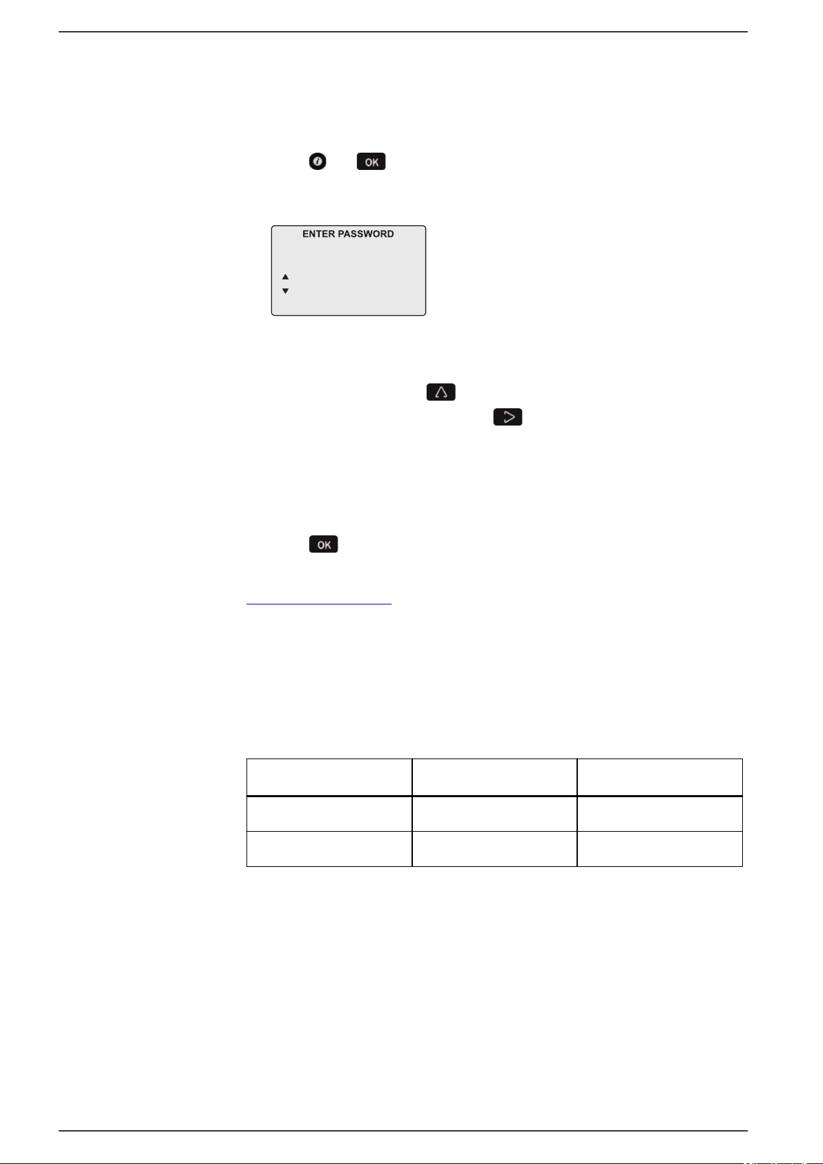
2.4.2. Logging on via the front panel
NOTE: To log on via the front panel, you need a password that consists of
digits only.
1. Press and on the front panel. The Enter password view opens.
Figure 1 - Enter password view
2. Enter the password for the desired access level.
Select a digit value using
move to the next digit position using
NOTE: There are 16 digit positions in the Enter password view. Enter the
password starting from the first digit position.
For example, if the password is 2, you can enter 2***, **2*, ***2, or 0002
to log on.
3. Press
Related topics
Password management on page 29
to confirm the password.
2.4.3. HTTP and FTP logon details
You can log on to the HTTP server and FTP using these user names and
passwords.
Table 12 - HTTP and FTP logon details
Protocol User name Password
, and if the password is longer than one digit,
.
28 P3U/en M/F005
HTTP conf 2
FTP easergy 2
Page 29

2. Product introduction
2.4.4. Password management
CYBERSECURITY HAZARD
To improve cybersecurity:
• Change all passwords from their default values when taking the protection
device into use.
• Change all passwords regularly.
Failure to follow these instructions can increase the risk of unauthorized
access.
You can change the password for the operator or configurator user accounts in
the General > Device info setting view in Easergy Pro.
The password can contain letters, digits or any other UTF-8 characters (total 1–32
characters). However, the new password cannot be any of the default passwords
(digits 0–4 or 9999).
Universal Relays P3U10, P3U20 and P3U30
NOTICE
NOTE: To log on via the front panel, you need a password that consists of
digits only.
Related topics
Logging on via the front panel on page 28
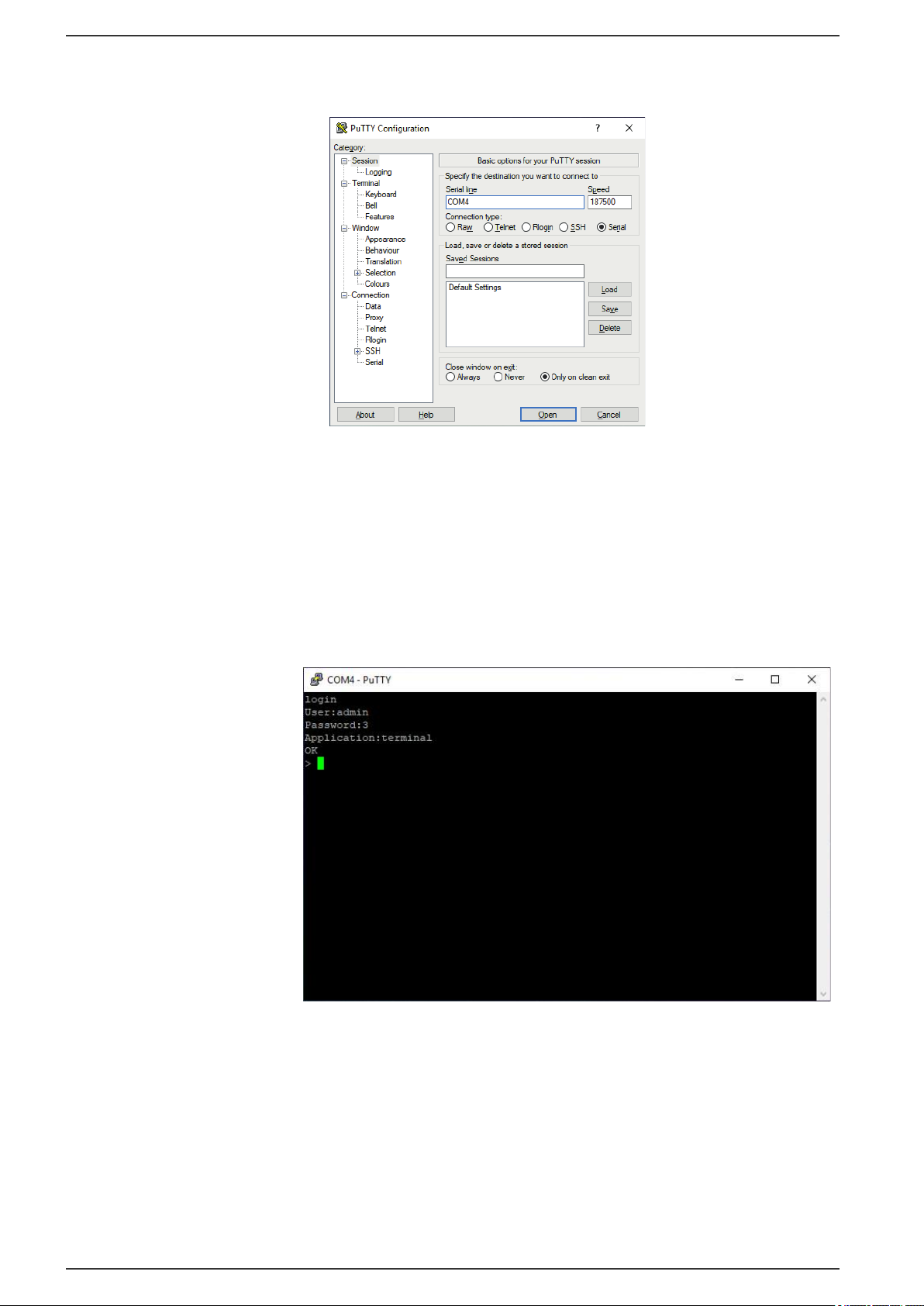
2.4.5. Changing passwords for administrator and configurator accounts via PuTTY
Change the password for the administrator and configurator user accounts to
reach an optimal cybersecurity level. To log on as the administrator user, you
need to use either a serial terminal software or a Telnet client software. This
instruction describes how to change the passwords using PuTTY which is freely
available at https://www.putty.org/.
1. Download and install PuTTY.
2. Connect the Easergy P3 device to your PC via the USB port in the device's
front panel.
3. Find the COM port number for the device (for example, with Easergy Pro).
4. Connect to the device’s COM port via PuTTY.
a. Open PuTTY.
The PuTTY Configuration dialog box opens.
P3U/en M/F005 29
Page 30
Universal Relays P3U10, P3U20 and P3U30
2. Product introduction
Figure 2 - PuTTY Configuration dialog box
b. In the Serial line field, type the COM port name.
c. In the Speed field, set the communication speed to 187500 bps.
d. Click Open.
The PuTTY command window opens.
5. Log on as the administrator by giving command login.
Figure 3 - PuTTY login
6. Change the password for the administrator account by giving the command
passwd.
30 P3U/en M/F005
Page 31

2. Product introduction Universal Relays P3U10, P3U20 and P3U30
Figure 4 - Changing the administrator password in PuTTY
7. Change the password for the configurator account by giving the command
passwd conf.
Figure 5 - Changing the configurator password in PuTTY
8. Log out by giving the command logout.
2.4.6. Password restoring
If you have lost or forgotten all passwords, contact Schneider Electric to restore
the default passwords.
P3U/en M/F005 31
Page 32

A
B
C
G
E
F
C
D
Universal Relays P3U10, P3U20 and P3U30 2. Product introduction
2.5. Front panel
Figure 6 - Easergy P3U10, P3U20 and P3U30 front panel
2.5.1. Push-buttons
A. LCD
B. Navigation push-buttons
C. Object control buttons
D. LED indicators
E. Local port
F. Function push-buttons and LEDs showing their status
G. INFO push-button
Symbol Function
HOME/CANCEL push-button for returning to the previous menu. To return to
the first menu item in the main menu, press the button for at least 3 seconds.
INFO push-button for viewing additional information, for entering the password
view and for adjusting the LCD contrast.
Programmable function push-button.
13
Programmable function push-button.
32 P3U/en M/F005
13
Page 33

2. Product introduction
Universal Relays P3U10, P3U20 and P3U30
ENTER push-button for activating or confirming a function.
UP navigation push-button for moving up in the menu or increasing a numerical
value.
DOWN navigation push-button for moving down in the menu or decreasing a
numerical value.
LEFT navigation push-button for moving backwards in a parallel menu or
selecting a digit in a numerical value.
RIGHT navigation push-button for moving forwards in a parallel menu or
selecting a digit in a numerical value.
Circuit breaker close push-button
Circuit breaker trip push-button
13
The default names of the function buttons are Function button 1 and 2. You can change the names
of the buttons in the Inputs/outputs > Names for logic outputs setting view.
2.5.2. LED indicators
The relay has 12 LED indicators on the front panel:
• two LEDs for function buttons (F1 and F2)
• two LEDs represent the unit's general status (power and service)
• eight user-configurable LEDs (A-H)
When the relay is powered, the power LED is green. During normal use, the
service LED is not active, it activates only when an error occurs or the relay is not
operating correctly. Should this happen, contact your local representative for
further guidance. The service LED and watchdog contact are assigned to work
together. Hardwire the status output into the substation's automation system for
alarm purposes.
To customize the LED texts on the front panel for the user-configurable LEDs, the
text may be created using a template and then printed. The printed text may be
placed in the pockets beside the LEDs.
You can also customize the LED texts that are shown on the screen for active
LEDs via Easergy Pro.
P3U/en M/F005 33
Page 34

Universal Relays P3U10, P3U20 and P3U30
Table 13 - LED indicators and their information
2. Product introduction
LED indicator
Power LED lit
Service LED lit
A–H LED lit Yellow Application-related
F1 or F2 LED lit Yellow Corresponding
LED color
Green
Red
Meaning Measure /
The auxiliary power
has been switched
on
Internal fault.
Operates in parallel
with the selfsupervision output
status indicators.
function key
pressed / activated
Remarks
Normal operation
state
The relay attempts
to reboot. If the
service LED remains
lit, call for
maintenance.
Configurable in the
Matrix setting view
Depending on the
function
programmed to F1 /
F2
2.5.3. Controlling the alarm screen
You can enable or disable the alarm screen either via the relay's local display or
using Easergy Pro:
• On the local display, go to Events > Alarms.
• In Easergy Pro, go to General > Local panel conf.
2.5.4. Accessing operating levels
1. On the front panel, press
2. Enter the password, and press
2.5.5. Adjusting the LCD contrast
Prerequisite: You have entered the correct password.
1. Press
, and adjust the contrast.
and .
.
◦ To increase the contrast, press
◦ To decrease the contrast, press
2. To return to the main menu, press
.
.
.
NOTE: By nature, the LCD display changes its contrast depending on the
ambient temperature. The display may become dark or unreadable at low
temperatures. However, this condition does not affect the proper operation of
the protection or other functions.
34 P3U/en M/F005
Page 35

2. Product introduction
2.5.6. Testing the LEDs and LCD screen
You can start the test sequence in any main menu window.
To start the LED and LCD test:
1. Press .
Universal Relays P3U10, P3U20 and P3U30
2. Press
The relay tests the LCD screen and the functionality of all LEDs.
.
2.5.7. Controlling an object with selective control
Prerequisite: You have entered the correct password and enabled selective
control in the Objects setting view.
When selective control is enabled, the control operation needs confirmation
(select before operate).
1. Press
◦ Press
◦ Press
2. Press
◦ Press
◦ Press
to close an object.
again to confirm.
to cancel.
to trip an object.
again to confirm.
to cancel.
2.5.8. Controlling an object with direct control
Prerequisite: You have entered the correct password and enabled selective
control in the Objects setting view.
When direct control is enabled, the control operation is done without confirmation.
1. Log into the system.
2. Press
3. Press
to close an object.
to trip an object.
2.5.9. Menus
This section gives an overview of the menus that you can access via the device's
front panel.
The main menu
Press the right arrow to access more measurements in the main menu.
P3U/en M/F005 35
Page 36

Universal Relays P3U10, P3U20 and P3U30 2. Product introduction
Table 14 - Main menu
Menu name Description
Active LEDs User-configurable texts for active LEDs
Measurements User-configurable measurements
Single line Single line or Single line mimic, measurements and control view. This
is a default start view. To return to this view from any location, press
the HOME/CANCELL button for at least 3 seconds.
Info Information about the relay: relay's name, order code, date, time and
firmware version
P Power: power factor and frequency values calculated by the relay.
Press the right arrow to view more energy measurements.
E Energy: the amount of energy that has passed through the protected
line, calculated by the relay from the currents and voltages. Press the
right arrow to view more energy measurements.
I Current: phase currents and demand values of phase currents. Press
the right arrow to view more current measurements.
V Line-to-line voltages. Press the right arrow to view other voltage
measurements.
Dema Minimum and maximum phase current and power demand values
Vmax Minimum and maximum values of voltage and frequency
Imax Minimum and maximum voltage values
Pmax Minimum and maximum power values
Month Monthly maximum current and power values
FL Short-circuit locator applied to incomer or feeder
Evnt Event log: event codes and time stamps
DR Disturbance recorder configuration settings
Runh Running hour counter
TIMR Timers: programmable timers that you can use to preset functions
DI Digital input statuses and settings
DO Digital output statuses and settings
Prot Protection: settings and statuses for various protection functions
50/51-1–50/51-4 Protection stage settings and statuses. The availability of the menus
are depends on the activated protection stages.
AR Auto-reclosure settings, statuses and registers
36 P3U/en M/F005
Page 37

Main menu Submenus
Arc detection settings
I pick-up setting
ARC
OK
OK OK
2. Product introduction
Universal Relays P3U10, P3U20 and P3U30
Menu name Description
OBJ Objects: settings related to object status data and object control (open/
closed)
Lgic Logic events and counters
CONF General device setup: CT and VT scalings, frequency adaptation,
units, device info, date, time, clock, etc.
Bus Communication port settings
OPT Slot info: card ID (CID) that is the name of the card used by the relay
firmware
Diag Diagnosis: various diagnostic information
2.5.9.1. Moving in the menus
Figure 7 - Moving in menus using the front panel
• To move in the main menu, press or .
• To move in the submenus, press
• While in the submenu, press
• To enter a submenu, press
or .
or to jump to the root.
and use or for moving down or up
in the menu.
• To edit a parameter value, press
• Enter the password, and press
• To go back to the previous menu, press
P3U/en M/F005 37
and .
.
.
Page 38

Universal Relays P3U10, P3U20 and P3U30
• To go back to the first menu item in the main menu, press for at least three
seconds.
NOTE: To enter the parameter edit mode, enter the password. When the
value is in edit mode, its background is dark.
2.5.9.2. Local panel messages
Table 15 - Local panel messages
Value is not editable: The value can not be edited or password is not given
Control disabled: Object control disabled due to wrong operating level
Change causes autoboot: Notification that if the parameter is changed the relay boots
itself
2.6. Easergy Pro setting and configuration tool
2. Product introduction
DANGER
HAZARD OF ELECTRIC SHOCK, EXPLOSION, OR ARC
FLASH
Only qualified personnel should operate this equipment.
Such work should be performed only after reading this
entire set of instructions and checking the technical
characteristics of the device.
Failure to follow this instruction will result in death or
serious injury.
Easergy Pro is a software tool for configuring Easergy P3 relays. It has a
graphical interface where the relay settings and parameters are grouped under
seven tabs:
• General
• Measurements
• Inputs/outputs
• Protection
• Matrix
• Logs
• Communication
The contents of the tabs depend on the relay type and the selected application
mode.
Easergy Pro stores the relay configuration in a setting file. The configuration of
one physical relay is saved in one setting file. The configurations can be printed
out and saved for later use.
For more information, see the Easergy Pro user manual.
NOTE: Download the latest version of the software from www.schneider-
electric.com/en/product-range/64884-easergy-p3.
38 P3U/en M/F005
Page 39

2. Product introduction Universal Relays P3U10, P3U20 and P3U30
NOTICE
RISK OF SYSTEM SHUTDOWN
After writing new settings or configurations to a relay, perform a test to verify that
the relay operates correctly with the new settings.
Failure to follow these instructions can result in unwanted shutdown of
the electrical installation.
P3U/en M/F005 39
Page 40

Universal Relays P3U10, P3U20 and P3U30 3. Measurement functions
3. Measurement functions
Easergy P3 has various amounts of analog inputs depending on the model in use.
Table 16 - Measurement functions in Easergy P3 on page 40 introduces directly
measured and calculated quantities for the power system monitoring. Also see
2.3. Product selection guide on page 19.
The relay has two operational modes: feeder and motor. In the feeder mode, the
secondary currents are proportional to the CT values whereas in the motor mode,
all protection stages use the motor's nominal current values.
The current scaling impacts the following functions:
• Protection stages
• Measurements
• Disturbance recorder
• Fault location calculation
Table 16 - Measurement functions in Easergy P3
Measurements
Specification
P3U10/20 P3U30 P3x3x Measurement
range
RMS phase current ■ ■ ■ 0.025-50 x I
RMS ground fault
■ ■ ■ 0.003-2 x I
overcurrent
RMS line-to-line voltage — ■ ■
RMS phase-to-neutral
— ■ ■
0.005-1.7 x V
0.005-1.7 x V
voltage
RMS active power (PF >0.5) — ■ ■ ±0.1-1.5 x P
RMS reactive power (PF
— ■ ■ ±0.1-1.5 x Q
>0.5)
Inaccuracy
N
N
N
N
N
N
I ≤ 1.5 x IN: ±0.5 % of value or ±15
mA
I > 1.5 x IN: ±3 % of value
I ≤ 1.5 xI0N: ±0.3 % of value or ±0.2
% of I0N
I > 1.5 xI0N: ±3 % of value
±0.5 % or ±0.3 V
±0.5 % or ±0.3 V
±1 % for range 0.3-1.5xP
±3 % for range 0.1-0.3xP
±1 % for range 0.3-1.5xQ
±3 % for range 0.1-0.3xQ
N
N
N
N
RMS apparent power (PF
— ■ ■ ±0.1-1.5 x S
N
±1 % for range 0.3-1.5xS
N
>0.5)
±3 % for range 0.1-0.3xS
N
Frequency ■ ■ ■ 16 Hz – 75 Hz ±10 mHz
Fundamental frequency
current values
■ ■ ■ 0.025-50 x I
N
I ≤ 1.5 x IN: ±0.5 % of value or ±15
mA
I > 1.5 x IN: ±3 % of value
Fundamental frequency
— ■ ■
0.005-1.7 x V
N
±0.5 % or ±0.3 V
voltage values
40 P3U/en M/F005
Page 41

3. Measurement functions Universal Relays P3U10, P3U20 and P3U30
Measurements
Specification
Fundamental frequency
P3U10/20 P3U30 P3x3x Measurement
range
— ■ ■ ±0.1-1.5 x P
N
Inaccuracy
±1 % for range 0.3-1.5xP
active, reactive and apparent
power values
Fundamental frequency
— ■ ■ ±0.1-1.5 x Q
N
±3 % for range 0.1-0.3xP
±1 % for range 0.3-1.5xQ
active power values
±3 % for range 0.1-0.3xQ
Fundamental frequency
— ■ ■ ±0.1-1.5 x S
N
±1 % for range 0.3-1.5xS
reactive power values
±3 % for range 0.1-0.3xS
Power factor — ■ ■ 0.02-1 ±2° or ±0.02 for PF > 0.5
Active energy — ■ ■
Reactive energy — ■ ■
±1 % for range 0.3-1.5xEP
±1 %/1h for range 0.3-1.5xEQ
±3 %/1h for range 0.1-0.3xEQ
Energy transmitted with
— ■ ■
±1 %/1h for range 0.3-1.5xEP
pulse outputs
±3 %/1h for range 0.1-0.3xEP
N
N
N
N
N
N
N
N
N
N
N
Demand values: phase
currents
■ ■ ■ 0.025-50 x I
N
I ≤ 1.5 x IN: ±0.5 % of value or ±15
mA
I > 1.5 x IN ±3 % of value
Active power demand — ■ ■ ±0.1-1.5 x P
N
±1 % for range 0.3-1.5xP
±3 % for range 0.1-0.3xP
Reactive power demand — ■ ■ ±0.1-1.5 x Q
N
±1 % for range 0.3-1.5xQ
±3 % for range 0.1-0.3xQ
Apparent power demand — ■ ■ ±0.1-1.5 x S
N
±1 % for range 0.3-1.5xS
±3 % for range 0.1-0.3xS
Power factor demand — ■ ■ ±2° or ±0.02 for PF > 0.5
Min and max demand
values: phase currents
■ ■ ■
0.025-50 x I
N
I ≤ 1.5 x IN: ±0.5 % of value or ±15
mA
I > 1.5 x IN ±3 % of value
Min and max demand
values: RMS phase currents
■ ■ ■
0.025-50 x I
N
I ≤ 1.5 x IN: ±0.5 % of value or ±15
mA
N
N
N
N
N
N
I > 1.5 x IN ±3 % of value
Min and max demand
— ■ ■
±1 % for range 0.3-1.5xPN, QN, S
N
values: active, reactive,
apparent power and power
±3 % for range 0.1-0.3xPN, QN, S
N
factor
P3U/en M/F005 41
Page 42

Universal Relays P3U10, P3U20 and P3U30
3. Measurement functions
Measurements
Specification
Maximum demand values
over the last 31 days and 12
months: active, reactive,
apparent power
Minimum demand values
over the last 31 days and 12
months: active, reactive
power
Max and min values:
currents
Max and min values:
voltages
Max and min values:
frequency
P3U10/20 P3U30 P3x3x Measurement
range
— ■ ■
— ■ ■
■ ■ ■
— ■ ■
■ ■ ■
0.025-50 x I
0.005-1.7 x V
N
N
16 Hz-75 Hz ±10 mHz
Inaccuracy
±1 % for range 0.3-1.5xPN, QN, S
±3 % for range 0.1-0.3xPN, QN, S
±1 % for range 0.3-1.5xPN, QN, S
±3 % for range 0.1-0.3xPN, QN, S
I ≤ 1.5 x IN: ±0.5 % of value or ±15
mA
I > 1.5 x IN ±3 % of value
±0.5 % or ±0.3 V
N
N
N
N
Max andmin values: active,
— ■ ■
±0.1-1.5 x PN, QN, SN±1 % for range 0.3-1.5xPN, QN, S
reactive, apparent power
and power factor
Harmonic values of phase
■ ■ ■
2nd-15th
current and THD
Harmonic values of voltage
— ■ ■
2nd-15th
and THD
Voltage sags and swells — ■ ■
0.005-1.7 x V
N
NOTE: Measurement display's refresh rate is 0.2 s.
3.1. Primary, secondary and per unit scaling
Many measurement values are shown as primary values although the relay is
connected to secondary signals. Some measurement values are shown as
relative values - per unit or percent. Almost all start setting values use relative
scaling.
±3 % for range 0.1-0.3xPN, QN, S
±2° or ±0.02 for PF > 0.5
±2° or ±0.02 for PF > 0.5
N
N
42 P3U/en M/F005
Page 43

3. Measurement functions Universal Relays P3U10, P3U20 and P3U30
Scaling settings
Table 17 - Phase current and ground fault overcurrent scaling parameters
Parameter Description
Nominal input (IL side) Rated value of the phase current input. The given
thermal withstand, burden and impedance are
based on this value.
See Table 130 - Measuring circuits on page 315 for
details.
CT primary Primary current value of the IL current transformer
CT secondary Secondary current value of the IL current
transformer
IN1 CT primary Primary current value of the ground fault I
N1
overcurrent transformer
IN1 CT secondary Secondary current value of the ground fault I
N1
overcurrent transformer
Nominal IN1 input
Selectable nominal input rating for the ground fault
overcurrent input. Select either 5A or 1A depending
on which Io input is used. The given thermal
withstand, burden and impedance are based on this
value.
See Table 130 - Measuring circuits on page 315 for
details.
VT primary Primary voltage value of the voltage transformer
(only P3U30 relays)
VT secondary Secondary voltage value of the voltage transformer
(only P3U30 relays)
VTo secondary Secondary voltage value of the neutral voltage
displacement voltage transformer
Voltage measurement mode The relay can be connected either to zero-
sequence voltage, line-to-line voltage or line-toneutral voltage. Set the voltage measurement mode
according to the type of connection used.
Frequency adaptation mode Parameter used to set the system frequency. There
are three modes available: manual, auto and fixed.
For more information, see section Frequency
adaptation mode.
Adapted frequency When the frequency adaption mode is set to
manual, you can set the frequency in the Adapted
frequency field, and it is not be updated even if the
measured frequency is different.
Angle memory duration Time setting for the directional overcurrent stage to
keep the phase angle fixed if the system voltage
collapses
P3U/en M/F005 43
Page 44

Universal Relays P3U10, P3U20 and P3U30
Figure 8 - Scaling setting view in Easergy Pro
3. Measurement functions
The scaling equations presented in 3.1.2. Current transformer ratio on page 45
and 3.1.3. Voltage transformer ratio on page 47 are useful when doing
secondary testing.
3.1.1. Frequency adaptation mode
You can set the system frequency in General > Scaling in Easergy Pro.
There are three frequency adaptation modes available:
• Manual: When the adaption mode is set to manual, you can set the frequency
in the Adapted frequency field, and it will not be updated even if the
measured frequency is different. However, the relay monitors the system
frequency internally and adapts to the new frequency even if the frequency
has been set manually.
• Auto: The network frequency is automatically updated when the relay has
measured the voltage for approximately 45 seconds. The Adapted frequency
field is updated even if it has been set previously. The frequency is measured
from the voltage signals.
44 P3U/en M/F005
Page 45

3. Measurement functions
Universal Relays P3U10, P3U20 and P3U30
Table 18 - Voltage signals
Voltage measurement mode Voltage Voltage channel
2LL+VN, 2LL+VN/LNy, 2LL+VN/LLy VAB, V
3LN, 3LN+VN, 3LN/LNy, 3LN/LLy VA, V
LN+V
N/y/z
LL+V
N/y/z
In P310 and P320 relays, the frequency adaptation is taken from the
measured currents.
• Fixed: The frequency is not updated based on the measured voltage and only
the set value is used. This mode is recommended to be used for the linedifferential function.
3.1.2. Current transformer ratio
NOTE: The rated value of the relay's current input, for example 5 A or 1 A,
does not have any effect on the scaling equations, but it defines the
measurement range and the maximum allowed continuous current. See Table
130 - Measuring circuits on page 315 for details.
V1, V
BC
B
V
A
V
AB
V1, V
V
1
V
1
2
2
For ground fault overcurrent to input IN, use the corresponding CT
values. For ground fault stages using I
values for CT
and CT
PRI
SEC
.
signals, use the phase current CT
N Calc
Examples
1. Secondary to primary
CT = 500 / 5
Current to the relay's input is 4 A.
=> Primary current is I
= 4 x 500 / 5 = 400 A
PRI
2. Primary to secondary
CT = 500 / 5
The relay displays I
=> Injected current is I
= 400 A
PRI
= 400 x 5 / 500 = 4 A
SEC
Per unit [pu] scaling
For phase currents:
1 pu = 1 x I
1.3. Abbreviations and terms on page 13.
See
= 100%, where I
MODE
is the rated current according to the mode.
MODE
and CT
PRI
SEC
For ground fault overcurrents
1 pu = 1 x CT
P3U/en M/F005 45
for secondary side and 1 pu = 1 x CT
SEC
for primary side.
PRI
Page 46

MODESEC
PRISEC
PU
ICT
CTI
I
⋅
⋅
=
SEC
SEC
PU
CT
I
I =
PRI
MODE
SECPUSEC
CT
I
CTII ⋅⋅=
SECPUSEC
CTII ⋅=
Universal Relays P3U10, P3U20 and P3U30
secondary → per unit
per unit → secondary
Examples
1. Secondary to per unit
CT = 750 / 5
Current injected to the relay's inputs is 7 A.
Per unit current is IPU = 7 / 5 = 1.4 pu = 140%
2. Secondary to per unit for phase currents
3. Measurement functions
Phase current scaling Ground fault overcurrent (3IN)
scaling
CT = 750/5
IN or I
MOT
= 525 A
Current injected to the relay's inputs is 7 A.
Per unit current is IPU = 7 x 750 / (5 x 525) = 2.00 pu = 2.00 x (IN or I
= 200%
3. Per unit to secondary
CT = 750 / 5
The relay setting is 2 pu = 200%.
Secondary current is I
= 2 x 5 = 10 A
SEC
4. Per unit to secondary for phase currents
CT = 750 / 5
IN or I
The relay setting is 2 x (IN or I
Secondary current is I
MOT
= 525 A
) = 2 pu = 200%.
MOT
= 2 x 5 x 525 / 750 = 7 A
SEC
5. Secondary to per unit for earth fault overcurrent
Input is IN.
CT0 = 50 / 1
Current injected to the relay's input is 30 mA.
Per unit current is IPU = 0.03 / 1 = 0.03 pu = 3%
MOT
)
6. Secondary to per unit for ground fault overcurrent
Input is IN.
CT0 = 50 / 1
The relay setting is 0.03 pu = 3%.
Secondary current is I
= 0.03 x 1 = 30 mA
SEC
7. Secondary to per unit for earth fault overcurrent
Input is I
N Calc
.
CT = 750 / 5
46 P3U/en M/F005
Page 47

3. Measurement functions
Universal Relays P3U10, P3U20 and P3U30
Currents injected to the relay's IA input is 0.5 A.
IB = IC = 0.
Per unit current is IPU = 0.5 / 5 = 0.1 pu = 10%
8. Secondary to per unit for earth fault overcurrent
Input is I
CT = 750 / 5
The relay setting is 0.1 pu = 10%.
If IB = IC = 0, then secondary current to IA is I
3.1.3. Voltage transformer ratio
NOTE: Voltage transformer scaling is based on the line-to-line voltages in all
voltage measurements modes.
Examples
1. Secondary to primary. Voltage measurement mode is "2LL+VN".
VT = 12000/110
Voltage connected to the relay's input VA or VB is 100 V.
=> Primary voltage is V
2. Secondary to primary. Voltage measurement mode is "3LN”.
VT = 12000/110
Three phase symmetric voltages connected to the relay's inputs VA, V
and VC are 57.7 V.
=> Primary voltage is V
N Calc
.
= 0.1 x 5 = 0.5 A
SEC
= 100x12000/110 = 10909 V.
PRI
B
= √3 x58x12000/110 = 10902 V
PRI
3. Primary to secondary. Voltage measurement mode is "2LL+VN".
VT = 12000/110
The relay displays V
=> Secondary voltage is V
= 10910 V.
PRI
SEC
= 10910x110/12000 = 100 V
4. Primary to secondary. Voltage measurement mode is "3LN”.
VT = 12000/110
The relay displays VAB = VBC = VCA = 10910 V.
=> Symmetric secondary voltages at VA, VB and VC are V
= 10910/√3
SEC
x110/12000 = 57.7 V.
Per unit [pu] scaling of line-to-line voltages
One per unit = 1 pu = 1 x VN = 100%, where VN = rated voltage of the VT.
P3U/en M/F005 47
Page 48

N
PRI
SEC
SEC
PU
V
VT
VT
V
V
⋅=
N
PRI
SEC
SEC
PU
V
VT
VT
V
V
⋅⋅= 3
PRI
N
SECPUSEC
VT
V
VTV
V
⋅⋅=
PRI
NSEC
PUSEC
VT
VVT
V
V
⋅⋅=
3
Universal Relays P3U10, P3U20 and P3U30
3. Measurement functions
Line-to-line voltage scaling
Voltage measurement mode =
"2LL+VN", "1LL+VN/LLy", "2LL/
Voltage measurement
mode = "3LN"
LLy", "LL/LLy/LLz"
secondary → per
unit
per unit →
secondary
Examples
1. Secondary to per unit. Voltage measurement mode is "2LL+VN".
VT = 12000/110
Voltage connected to the relay's input VA or VB is 110 V.
=> Per unit voltage is VPU = 110/110 = 1.00 pu = 1.00 x VN = 100%
2. Secondary to per unit. Voltage measurement mode is "3LN".
VT = 12000/110
Three symmetric phase-to-neutral voltages connected to the relay's inputs
VA, VB and VC are 63.5 V
=> Per unit voltage is VPU = √3 x 63.5/110 x 12000/11000 = 1.00 pu =
1.00xVN = 100%
3. Per unit to secondary. Voltage measurement mode is "2LL+VN".
VT = 12000/110
The relay displays 1.00 pu = 100%.
=> Secondary voltage is V
= 1.00 x 110 x 11000/12000 = 100.8 V
SEC
4. Per unit to secondary. Voltage measurement mode is "3LN".
VT = 12000/110
VN = 11000 V
The relay displays 1.00 pu = 100%.
=> Three symmetric phase-to-neutral voltages connected to the relay 's
inputs VA, VB and VC are V
= 1.00 x 110/√3 x 11000/12000 = 58.2 V
SEC
48 P3U/en M/F005
Page 49

SEC
SEC
PU
V
V
V
0
=
3
1
SEC
cba
SEC
PU
VVV
VT
V
++
⋅=
SECPUSEC
VVV
0
⋅=
SECPU
SEC
cba
VTVVVV ⋅⋅=++ 3
3. Measurement functions
Universal Relays P3U10, P3U20 and P3U30
Per unit [pu] scaling of neutral overvoltage
Neutral overvoltage (VN) scaling
Voltage measurement mode
= "2LL+VN", "1LL+VN/LLy"
secondary → per unit
per unit →secondary
Voltage measurement
mode = "3LN"
Examples
1. Secondary to per unit. Voltage measurement mode is "2LL+VN".
V
= 110 V (This is a configuration value corresponding to VN at full
0SEC
ground fault.)
Voltage connected to the relay's input VC is 22 V.
=> Per unit voltage is VPU = 22/110 = 0.20 pu = 20%
2. Secondary to per unit. Voltage measurement mode is "3LN".
VT = 12000/110
Voltage connected to the relay's input VA is 38.1 V, while VA = VB = 0.
=> Per unit voltage is VPU = (38.1+0+0)/(√3 x110) = 0.20 pu = 20%
3. Per unit to secondary. Voltage measurement mode is "2LL+VN".
V
= 110 V (This is a configuration value corresponding to VN at full
0SEC
ground fault.)
The relay displays VN = 20%.
=> Secondary voltage at input VC is V
4. Per unit to secondary. Voltage measurement mode is "3LN".
VT = 12000/110
The relay displays VN = 20%.
=> If VB = VC = 0, then secondary voltages at VA is V
38.1 V
3.2. Measurements for protection functions
The relay uses root mean square (RMS) measurement for the protection stages if
not stated otherwise in the protection stage description.
= 0.20 x 110 = 22 V
SEC
= √3 x 0.2 x 110 =
SEC
P3U/en M/F005 49
Page 50

0.00 0.05 0.10 0.15 0.20 0.25 0.30
-10
-5
0
5
rms
I
B
f1
f2
0
50
100
f2/f1 (%)
Current (PU)
Time (s)
Load = 0%
Relative 2nd harmoic f2/f1 (%)
2
15
2
2
2
1
...
fffRMS
IIII +++=
2
15
2
2
2
1
...
fffRMS
VVVV +++=
Universal Relays P3U10, P3U20 and P3U30
Figure 9 - Example of various current values of a transformer inrush current
3. Measurement functions
3.3. RMS values
All the direct measurements and most protection functions are based on
fundamental frequency values.
Figure 9 - Example of various current values of a transformer inrush current on
page 50 shows a current waveform and the corresponding fundamental frequency
component f1, second harmonic f2, and RMS value in a special case where the
current deviates significantly from a pure sine wave.
RMS currents
The relay calculates the RMS value of each phase current. The minimum and
maximum RMS values are recorded and stored (see 3.6. Minimum and maximum
values on page 53).
RMS voltages
The relay calculates the RMS value of each voltage input. The minimum and the
maximum of RMS values are recorded and stored (see 3.6. Minimum and
maximum values on page 53).
3.4. Harmonics and total harmonic distortion (THD)
The relay calculates the the total harmonic distortions (THDs) as a percentage of
the currents and voltages values measured at the fundamental frequency. The
relay calculates the harmonics from the 2nd to the 15th of phase currents and
50 P3U/en M/F005
Page 51

1
15
2
h
T
HD
i
2
f
i
∑
=
=
%2.13
100
8310
222
=
++
=THD
ARMS 9.1008310100
2222
=+++=
3. Measurement functions
Universal Relays P3U10, P3U20 and P3U30
voltages. (The 17th harmonic component is also shown partly in the value of the
15th harmonic component. This is due to the nature of digital sampling.)
The harmonic distortion is calculated:
Equation 1
f1 = Fundamental value
f
= Harmonics
2– 15
Example
f1 = 100 A, f3 = 10 A, f7 = 3 A, f11 = 8 A
For reference, the RMS value is:
Another way to calculate the THD is to use the RMS value as reference instead of
the fundamental frequency value. In the example above, the result would then be
13.0 %.
3.5. Demand values
The device calculates average values (demand values) of phase currents IA, IB, I
and power values S, P and Q.
The demand time is configurable from 10 to 60 minutes with the parameter
"Demand time".
C
P3U/en M/F005 51
Page 52

Universal Relays P3U10, P3U20 and P3U30 3. Measurement functions
Figure 10 - Demand values
Table 19 - Demand value parameters
Parameter Value Unit Description
Set
Time 10 – 30 min Demand time (averaging time) Set
Fundamental frequency values
IAda A Demand of phase current I
IBda A Demand of phase current I
ICda A Demand of phase current I
A
B
C
Pda kW Demand of active power P
PFda Demand of power factor PF
Qda kvar Demand of reactive power Q
Sda kVA Demand of apparent power S
RMS values
IARMSda A Demand of RMS phase current I
A
14
IBRMSda A Demand of RMS phase current I
ICRMSda A Demand of RMS phase current I
B
C
Prmsda kW Demand of RMS active power P
Qrmsda kvar Demand of RMS reactive power Q
Srmsda kVA Demand of RMS apparent power S
14
Set = An editable parameter (password needed)
52 P3U/en M/F005
Page 53

3. Measurement functions
3.6. Minimum and maximum values
Minimum and maximum values are registered with time stamps since the latest
manual clearing or since the relay has been restarted. The available registered
values are listed in Table 20 - Minimum and maximum measurement values on
page 53.
Figure 11 - Minimum and maximum values
Universal Relays P3U10, P3U20 and P3U30
Table 20 - Minimum and maximum measurement values
Min & Max measurement Description
IA, IB, I
C
I
, I
B RMS
, I
C RMS
D
A RMS
I
N
VA, VB, VC, V
VARMS, VBRMS, VCRMS, VDRMS Line-to-neutral voltages, RMS value
V
N
f Frequency
P, Q, S Active, reactive, apparent power
IA da, IBda, ICda Demand values of phase currents
IAda, IBda, ICda (rms value) Demand values of phase currents, rms values
Phase current, fundamental frequency value
Phase current, RMS value
Ground fault overcurrent, fundamental value
Voltages, fundamental frequency values
Neutral voltage displacement, fundamental value
PFda Power factor demand value
P.F. Power factor
The clearing parameter "ClrMax" is common for all these values.
P3U/en M/F005 53
Page 54

Universal Relays P3U10, P3U20 and P3U30 3. Measurement functions
Table 21 - Parameters
Parameter Value Description
ClrMax -; Clear Reset all minimum and maximum values Set
15
Set = An editable parameter (password needed).
3.7. Maximum values of the last 31 days and 12 months
The maximum and minimum values of the last 31 days and the last 12 months
are stored in the relay's non-volatile memory. You can view them in the Month
max setting view in Easergy Pro.
NOTE: The saving process starts every 30 minutes and it takes a while. If the
relay's auxiliary supply power is switched off before all values have been
saved, the old values remain for the unsaved ones.
Corresponding time stamps are stored for the last 31 days. The registered values
are listed in
months on page 55.
Figure 12 - Maximum and minimum values of the past 31 days
Table 22 - Maximum registered values of the last 31 days and 12
Set
15
54 P3U/en M/F005
Page 55

3. Measurement functions Universal Relays P3U10, P3U20 and P3U30
Figure 13 - Maximum and minimum values of the past 12 months
Table 22 - Maximum registered values of the last 31 days and 12 months
12
months
Max Min Descriptio
n
31
days
Measur
ement
IA, IB, I
C
I
N
S X Apparent
P X X Active power X X
Q X X Reactive
X Phase
current
(fundamental
frequency
value)
X Ground fault
overcurrent
X X
power
X X
power
12
months
The timebase can be a value from one cycle to one minute. Also a demand value
can be used as the timebase and its value can be set between 10 and 60
minutes. The demand value menu is located under the Measurements view.
Table 23 - Parameters of the day and month registers
Parameter Value Description
Timebase Parameter to select the type of the registered values Set
20 ms
P3U/en M/F005 55
Collect min & max of one cycle values
17
Set
16
Page 56

I
V
REF
+ind
cos =+
PF=+
+cap
cos =+
PF =
ind
cos =
PF=+
cap
cos =
PF =
0°
+90°
III
III IV
Universal Relays P3U10, P3U20 and P3U30 3. Measurement functions
Parameter Value Description
200 ms Collect min & max of 200 ms average values
1 s Collect min & max of 1 s average values
1 min Collect min & max of 1 minute average values
demand Collect min & max of demand values (3.5. Demand
values on page 51)
ResetDays Reset the 31 day registers Set
ResetMon Reset the 12 month registers Set
16
Set = An editable parameter (password needed)
17
This is the fundamental frequency RMS value of one cycle updated every 20 ms.
3.8. Power and current direction
Figure 14 - Quadrants of voltage/current phasor plane on page 56 shows the
concept of three-phase current direction and sign of cosφ and power factor PF
(the absolute value is equal to cosφ, but the sign is 'IND' for inductive i.e. lagging
current and 'CAP' for capacitive i.e. leading current). Figure 15 - Quadrants of
power plane on page 57 shows the same concepts on a PQ power plane.
Set
16
Figure 14 - Quadrants of voltage/current phasor plane
I: Forward capacitive power, current is leading
II: Reverse inductive power, current is leading
56 P3U/en M/F005
III: Reverse capacitive power, current is lagging
IV: Forward inductive power, current is lagging
Page 57

S
P
Q
+ind
cos =+
PF=+
+cap
cos =+
PF =
ind
cos =
PF=+
cap
cos =
PF =
0°
+90°
III
III IV
3. Measurement functions
Universal Relays P3U10, P3U20 and P3U30
Figure 15 - Quadrants of power plane
I: Forward inductive power, current is lagging
II: Reverse capacitive power, current is lagging
III: Reverse inductive power, current is leading
IV: Forward capacitive power, current is leading
Table 24 - Power quadrants
Power quadrant Current related
+ inductive Lagging Forward + +
+ capacitive Leading Forward + -
- inductive Leading Reverse - +
- capacitive Lagging Reverse - -
3.9. Symmetrical components
to voltage
Power direction cosφ Power factor
PF
In a three-phase system, the voltage or current phasors may be divided into
symmetrical components.
• Positive sequence 1
• Negative sequence 2
• Zero sequence 0
Symmetrical components are calculated according to the following equations:
P3U/en M/F005 57
Page 58

=
Saa
aa
S
S
S
2
2
2 C
S
B
S
A
1
0
1
1
111
3
1
2
3
2
1
1201 ja +−=°∠=
Universal Relays P3U10, P3U20 and P3U30 3. Measurement functions
S 0 = zero sequence component
S 1 = positive sequence component
S 2 = negative sequence component
, a phase rotating constant
SA = phasor of phase A (phase current or voltage)
SB = phasor of phase B
SC = phasor of phase C
58 P3U/en M/F005
Page 59

4. Control functions Universal Relays P3U10, P3U20 and P3U30
4. Control functions
4.1. Digital outputs
The digital outputs are also called controlling outputs, signaling outputs and selfsupervision outputs. Trip contacts can be controlled by using the relay output
matrix or logic functions. Also forced control is possible. To use forced control,
you must enable it in the Relays setting view.
Any internal signal can be connected to the digital outputs in the Matrix > output
matrix setting view. A digital output can be configured as latched or non-latched.
The digital output connections are configured either through the Easergy Pro
setting tool or the relay's menus. Horizontal lines represent outputs and vertical
lines outputs.. When the crossing line of the horizontal output signal and vertical
output line is touched, the connection changes in the following sequence:
The position of the contact can be checked in the “OUTPUT MATRIX” and
“RELAYS” menu. A digital output can be configured as latched or non-latched.
Latched relay contacts can be set free by pressing the “enter” key of the relay or
by releasing from the Easergy Pro setting tool.
The difference between trip contacts and signal contacts is the DC breaking
capacity. The contacts are single pole single throw (SPST) normal open (NO)
type, except signal relay A1 which has a changeover contact single pole double
throw (SPDT).
Programming matrix
1. Connected (single bullet)
2. Connected and latched (single bullet rounded with another circle)
3. Not connected (line crossing is empty)
Figure 16 - Trip contacts can be connected to protection stages or other similar
purpose in the Output matrix setting view
P3U/en M/F005 59
Page 60

Universal Relays P3U10, P3U20 and P3U30 4. Control functions
Figure 17 - Trip contacts can be assigned directly to outputs of logical operators
NOTE: Logic outputs are assigned automatically in the output matrix as well
when logic is built.
Trip contact status can be viewed and forced to operate in the Relays setting
view.
Figure 18 - Relays setting view
Power supply card outputs are not visible in the Relay config setting view.
Table 25 - Parameters of digital outputs
Parameter Value Unit Description Note
T1 – T7 0
Status of trip controlling output
1
A1
0
Status of alarm signalling output F
1
WD 0
1
Status of the WD relay
In Easergy Pro, it is called
"Service status output"
Force On
Off
Force flag for digital output
forcing for test purposes
Names for output relays (editable with Easergy Pro only)
Description String of
max. 32
Names for DO on Easergy Pro
screens. Default is
characte
rs
18
F = Editable when force flag is on
19
Set = An editable parameter (password needed).
18
F
F
Set
Set
19
60 P3U/en M/F005
Page 61

4. Control functions
4.2. Digital inputs
Universal Relays P3U10, P3U20 and P3U30
Digital inputs are available for control purposes.
The polarity normal open (NO) / normal closed (NC) and a delay can be
configured according to the application by using the front panel or Easergy Pro.
Digital inputs can be used in many operations. The status of the input can be
checked in the Output matrix and Digital inputs setting views. The digital inputs
make it possible to change group, block/enable/disable functions, to program
logics, indicate object status, etc.
The digital inputs require an external control voltage (ac or dc). The digital inputs
are activated after the activation voltage is exceeded. Deactivation follows when
the voltage drops below threshold limit.
Figure 19 - Digital inputs can be connected, latched or unlatched to trip contacts
or other similar purpose in Output matrix setting view
Figure 20 - Digital inputs can be assigned, latched or unlatched directly to inputs/
outputs of logical operators
If inputs are energized by using ac voltage, “mode” has to be selected as ac.
All essential information on digital inputs can be found in the same location in the
Digital inputs setting view. DI on/off events and alarm display (pop-up) can be
P3U/en M/F005 61
Page 62

VOLTAGE
1 s.
DIGITAL INPUT
1 s.
1
0
1
0
Universal Relays P3U10, P3U20 and P3U30 4. Control functions
enabled and disabled in Digital inputs setting view. Individual operation counters
are located in the same view as well.
Label and description texts can be edited with Easergy Pro according to the
demand. Labels are the short parameter names used on the local panel and
descriptions are the longer names used by Easergy Pro.
Digital input delay determines the activation and de-activation delay for the input.
Figure 21 - Digital input’s behavior when delay is set to 1 second on page
62shows how the digital input behaves when the delay is set to 1 second.
Figure 21 - Digital input’s behavior when delay is set to 1 second
Table 26 - Parameters of digital inputs
Parameter Value Unit Description Note
20
Mode dc, ac Used voltage of digital inputs
Input
DI1 – DI16
Number of digital input.
State 0, 1 Status of digital input 1 – digital input
x.
Polarity NO
NC
For normal open contacts (NO). Active
edge is 0 > 1
For normal closed contacts (NC)
Active edge is 1 > 0
Delay 0.00 – 60.00 s Definite delay for both on and off
transitions
On event On Active edge event enabled Set
Off Active edge event disabled
Off event On Inactive edge event enabled Set
Set
Set
Set
Off Inactive edge event disabled
Alarm display no No pop-up display Set
yes Alarm pop-up display is activated at
active DI edge
Counters 0 – 65535 Cumulative active edge counter (Set)
NAMES for DIGITAL INPUTS (editable with Easergy Pro only)
62 P3U/en M/F005
Page 63

4. Control functions
Universal Relays P3U10, P3U20 and P3U30
Parameter Value Unit Description Note
Label String of max. 10
characters
Description String of max. 32
characters
20
Set = An editable parameter (password needed).
4.3. Virtual inputs and outputs
There are virtual inputs and virtual outputs that can in many places be used like
their hardware equivalents except that they are located in the memory of the
relay. The virtual inputs act like normal digital inputs. The status of the virtual input
can be changed via the local display, communication bus and Easergy Pro. For
example setting groups can be changed using virtual inputs.
Virtual inputs can be used in many operations. The status of the input can be
checked in the Output matrix and Virtual inputs setting views. The status is also
visible on local mimic display, if so selected. Virtual inputs can be selected to be
operated with the function buttons F1 and F2, the local mimic or simply by using
the virtual input menu. Virtual inputs have similar functions as digital inputs: they
enable changing groups, block/enable/disable functions, to program logics and
other similar to digital inputs.
Short name for DIs on the local
display
Default is "DI1 – DIx". x is the
maximum number of the digital input.
Long name for DIs. Default is "Digital
input 1 – Digital input x".
x is the maximum number of the digital
input.
Set
Set
The activation and reset delay of the input is approximately 5 ms.
NOTE: The default names of the logic outputs are Logic output 1-n. You can
change the names of the outputs in the General > Names for logic outputs
setting view.
Table 27 - Virtual input and output
Number of inputs
Number of outputs
Activation time / Reset time < 5 ms
20
20
Figure 22 - Virtual inputs and ouputs can be used for many purpose in the Output
matrix setting view.
P3U/en M/F005 63
Page 64

Universal Relays P3U10, P3U20 and P3U30 4. Control functions
Figure 23 - Virtual inputs and outputs can be assigned directly to inputs/outputs of
logical operators.
Notice the difference between latched and non-latched connection.
Virtual input
The virtual inputs can be viewed, named and controlled in the Virtual inputs
setting view.
Figure 24 - Virtual inputs setting view
Table 28 - Parameters of virtual inputs
Parameter Value Unit Description
VI1-VI20 0
1
Events On
Off
64 P3U/en M/F005
Status of virtual input
Event enabling Set
Set
21
Page 65

4. Control functions Universal Relays P3U10, P3U20 and P3U30
Parameter Value Unit Description
NAMES for VIRTUAL INPUTS (editable with Easergy Pro only)
Label String of max. 10
characters
Description String of max. 32
characters
21
Set = An editable parameter (password needed).
Short name for VIs on the local
display
Default is "VIn", n = 1–20
Long name for VIs. Default is
"Virtual input n", n = 1–20
Set
Set
Set
Virtual output
In Easergy Pro, the Virtual outputs setting view is located Inputs/Outputs view.
Figure 25 - Virtual outputs setting view
21
Table 29 - Parameters of virtual outputs
Parameter Value Unit Description
VO1-VO20
Events On
NAMES for VIRTUAL OUTPUTS (editable with Easergy Pro only)
P3U/en M/F005 65
0
1
Off
Status of virtual output F
Event enabling Set
Set
22
Page 66

Directly
measured
values
Calculate
S, P, Q,
cosφ, tanφ,
symmetric
components
etc.
n
n
n
n
n
n
n
n
Virtual
inputs
Digital
inputs
optional
delay
and
inversion
I
V
DI
Protection stages
BLOCK
INPUT
BLOCK
INPUT
BLOCK
INPUT
START
TRIP
Block matrix Output matrix User’s logic
OUTPUTS
I
N
P
U
T
S
Output relays
and indicators
Output contacts
Virtual
outputs
Universal Relays P3U10, P3U20 and P3U30
4. Control functions
4.4. Matrix
Parameter Value Unit Description
Label String of
max. 10
Short name for VOs on the local
display
Set
Set
characte
rs
Description String of
Default is "VOn", n=1-20
Long name for VOs. Default is
Set
max. 32
characte
"Virtual output n", n=1-20
rs
22
Set = An editable parameter (password needed). F = Editable when force flag is on.
The relay has several matrices that are used for configuring the relay:
• Output matrix used to link protection stage signals, digital inputs, virtual
inputs, function buttons, object control, logic output, relay's internal alarms,
GOOSE signals and release latch signals to outputs, disturbance recorder trig
input and virtual outputs
• Block matrix used to block protection stages
• Object block matrix used to inhibit object control
• Auto-recloser matrix used to control auto-recloser
• Arc matrix used to control current and light signals to arc stages and arc
stages to the high-speed outputs
22
Figure 26 - Blocking matrix and output matrix
4.4.1. Output matrix
66 P3U/en M/F005
There are general-purpose LED indicators – "A", "B", "C" to ”H” – available for
customer-specific indications on the front panel. Their usage is define in a
separate output matrix.
Page 67

4. Control functions
Universal Relays P3U10, P3U20 and P3U30
There are two LED indicators specified for keys F1 and F2. The triggering of the
disturbance recorder (DR) and virtual outputs are configurable in the output
matrix.
A digital output or indicator LED can be configured as latched or non-latched. A
non-latched relay follows the controlling signal. A latched relay remains activated
although the controlling signal releases.
There is a common "release all latches" signal to release all the latched relays.
This release signal resets all the latched digital outputs and indicators. The reset
signal can be given via a digital input, via front panel or remotely through
communication. For instructions on how to release latches, see
latches on page 69.
Figure 27 - Trip and alarm relays together with virtual outputs can be assigned in
output matrix. Also automatic triggering of disturbance recorder is done in output
matrix.
4.5. Releasing
4.4.2. Blocking matrix
By means of a blocking matrix, the operation of any protection stage can be
blocked. The blocking signal can originate from the digital inputs or it can be a
start or trip signal from a protection stage or an output signal from the user's
programmable logic. In
block matrix on page 67 , an active blocking is indicated with a black dot (●) in
the crossing point of a blocking signal and the signal to be blocked.
Figure 28 - All protection stages can be blocked in the block matrix
Figure 28 - All protection stages can be blocked in the
P3U/en M/F005 67
Page 68

Universal Relays P3U10, P3U20 and P3U30
The Blocked status becomes visible only when the stage is about to activate.
Figure 29 - A view from the setting tool showing a DI input blocking connection
Figure 30 - Result for the I> stage when the DI is active and the stage exceeds its
current start value
4. Control functions
NOTICE
RISK OF NUISANCE TRIPPING
• The blocking matrix is dynamically controlled by selecting and deselecting
protection stages.
• Activate the protection stages first, then store the settings in a relay. After
that, refresh the blocking matrix before configuring it.
Failure to follow these instructions can result in unwanted shutdown of
the electrical installation.
4.4.3. Object block matrix
The object block matrix is used to link digital inputs, virtual inputs, function
buttons, protection stage outputs, logic outputs, alarm signals and GOOSE
signals to inhibit the control of objects, that is, circuit breakers, isolators and
grounding switches.
68 P3U/en M/F005
Page 69

4. Control functions
Typical signals to inhibit controlling of the objects like circuit breaker are:
• protection stage activation
• statuses of other objects
• interlocking made with logic
• GOOSE signals
These and other signals are linked to objects in the object block matrix.
There are also event-type signals that do not block objects as they are on only for
a short time, for example "Object1" open and "Object1 close" signals.
4.4.4. Auto-recloser matrix
The auto-recloser matrix is used to link digital inputs, virtual inputs, protection
stage outputs, object statuses, logic outputs, alarm signals and GOOSE signals to
control the auto-recloser. For more information, see
(ANSI 79) on page 199.
Universal Relays P3U10, P3U20 and P3U30
5.33. Auto-recloser function
4.5. Releasing latches
You can release latches using:
• Easergy Pro
• buttons and local panel display
• F1 or F2 buttons
4.5.1. Releasing latches using Easergy Pro
1. Connect Easergy Pro to the device.
2. From the Easergy Pro toolbar, select R > Release all latches.
Figure 31 - Releasing all latches
Alternatively, go to General>Release latches and from the drop-down menu,
select Release.
Figure 32 - Release latches
4.5.2. Releasing latches using buttons and local panel display
Prerequisite: You have entered the correct password
P3U/en M/F005 69
Page 70

Universal Relays P3U10, P3U20 and P3U30
1. Press .
2. Press .
4. Control functions
3. Select Release, and press
All latches are released.
.
4.5.3. Releasing latches using F1 or F2 buttons
You can use the function buttons F1 or F2 to release all latches after configuring
this function in Easergy Pro.
• To configure F1 to release latches:
a. In Easergy Pro, go to INPUTS/OUTPUT >FUNCTION BUTTONS.
b. For F1, select F1 from the Selected control drop-down menu.
Figure 33 - Function buttons > Selected control
c. Go to GENERAL > RELEASE LATCHES.
d. Select F1 from the DI to release latches drop-down menu.
e. Set 1 s delay for Latch release signal pulse.
Figure 34 - Release latches
After this, pressing the F1 button on the relay’s front panel releases all
latches.
NOTE: The latch release signal can be activated only if the latched
output is active.
4.6. Controllable objects
The relay allows controlling eight objects, that is, circuit breakers, disconnectors
and grounding switches by the "select before operate" or "direct control" principle.
70 P3U/en M/F005
Page 71

4. Control functions
Universal Relays P3U10, P3U20 and P3U30
Controlling is possible in the following ways:
• through the object control buttons
• through front panel and display using single-line diagram
• through the function keys
• through digital input
• through remote communication
• through Easergy Pro setting tool
• through Web server
• through Smart APP
The connection of an object to specific controlling outputs is done via an output
matrix (object 1–8 open output, object 1–8 close output). There is also an output
signal “Object failed” that is activated if the control of an object is not completed.
Object states
Each object has the following states:
Setting Value Description
Object state Undefined (00) Actual state of the object
Open
Close
Undefined (11)
Basic settings for objects
Each object has the following settings:
Setting Value Description
DI for ‘obj open’ None, any digital input, virtual
DI for ‘obj close’ Close information
DI for ‘obj ready’ Ready information
Max ctrl pulse length 0.02–600 s Pulse length for open and close
Completion timeout 0.02–600 s Timeout of ready indication
input or virtual output
Open information
commands. Control pulse stops
once object changes its state
Object control Open/Close Direct object control
If changing the states takes longer than the time defined by the “Max ctrl pulse
length” setting, the object is inoperative and the “Object failure” matrix signal is
set. Also, an undefined event is generated. “Completion timeout” is only used for
the ready indication. If “DI for ‘obj ready’” is not set, the completion timeout has no
meaning.
Output signals of objects
Each object has two control signals in matrix:
P3U/en M/F005 71
Page 72

Universal Relays P3U10, P3U20 and P3U30 4. Control functions
Output signal Description
Object x Open Open control signal for the object
Object x Close Close control signal for the object
These signals send control pulse when an object is controlled by digital input,
remote bus, auto-reclose etc.
4.6.1. Object control with digital inputs
Objects can be controlled with digital inputs, virtual inputs or virtual outputs. There
are four settings for each object:
Setting Active
DI for remote open / close control In remote state
DI for local open / close control In local state
If the relay is in local control state, the remote control inputs are ignored and vice
versa. An object is controlled when a rising edge is detected from the selected
input. The length of digital input pulse should be at least 60 ms.
4.6.2. Local or remote selection
In local mode, digital outputs can be controlled via the front panel but they cannot
be controlled via a remote serial communication interface.
In remote mode, digital outputs cannot be controlled via a front panel but they can
be controlled via a remote serial communication interface.
The local or remote mode can be selected by using the front panel or via one
selectable digital input. The digital input is normally used to change a whole
station to local or remote mode. You can select the L/R digital input in the Objects
setting view in Easergy Pro.
Table 30 - Local or remote selection
Action Control through Easergy
Local/Remote switch
status
Control through
Pro or SmartApp
Local Remote Local Remote
communication protocol
CB control Yes No No Yes
Setting or configuration
changes
Communication
configuration
Virtual inputs
23
Virtual inputs have a general parameter “Check L/R selection” for disabling the L/R check.
72 P3U/en M/F005
23
Yes Yes Yes Yes
Yes Yes Yes Yes
Yes No No Yes
Page 73

4. Control functions
4.6.3. Object control with Close and Trip buttons
The relay also has dedicated control buttons for objects. Close stands for object
closing and Trip controls object open command internally. Control buttons are
configured in the Objects setting view.
Table 31 - Parameters of function keys
Parameter Value Unit Description Set
Universal Relays P3U10, P3U20 and P3U30
Disabled
Object 1–8
Mode for control
butons
4.6.4. Object control with F1 and F2
Objects can be controlled with the function buttons F1 and F2.
By default, the F1 and F2 buttons are configured to control F1 and F2 variables
that can further be assigned to control objects.
-
Obj1–Obj8
Selective
Direct
Set
Button closes selected object if
password is enabled
Button opens selected object if
password is enabled
Control operation needs confirmation
(select before operate)
Control operation is done without
confirmation
Table 32 - Parameters of F1 and F2
Parameter Value State Pulse
length
F1 F1, V1-V20,
ObjCtrl
F2 F2, V1-V20,
ObjCtrl
24
Pulse length applies to values F1 and F2 only
0.1 0600 s
0.1 0-600 s
24
Description
controls F1, V1-V20 or
ObjCtrl parameters.
controls F2, V1-V20 and
ObjCtrl parameters.
You can configure the button funtions in the Inputs/outputs > Function buttons
setting view in Easergy Pro.
P3U/en M/F005 73
Page 74

Universal Relays P3U10, P3U20 and P3U30 4. Control functions
Figure 35 - Function buttons setting view
If ObjCtrl has been selected under Selected control, the selected object is
shown under Selected object. Otherwise, this column is empty.
When selecting ObjCtrl, link the function button to the appropriate object in the
General > Objects setting view.
Figure 36 - Ctrl object 2 setting view
4.7. Logic functions
The relay supports customer-defined programmable logic for boolean signals.
User-configurable logic can be used to create something that is not provided by
the relay as a default. You can see and modify the logic in the General > Logic
setting view in the Easergy Pro setting tool.
Table 33 - Available logic functions and their memory use
Logic
functions
AND 1
OR 1
74 P3U/en M/F005
No. of gates
reserved
Max. no. of input gates Max. no. of
logic
outputs
32
(An input gate can include any
number of inputs.)
20
Page 75

4. Control functions Universal Relays P3U10, P3U20 and P3U30
Logic
functions
No. of gates
reserved
Max. no. of input gates Max. no. of
logic
outputs
XOR 1
AND+OR 2
CT (count+reset) 2
INVAND 2
INVOR 2
OR+AND 2
RS (set+reset) 2
RS_D (set+D
+load+reset)
4
The consumed memory is dynamically shown on the configuration view in
percentage. The first value indicates the memory consumption of inputs, the
second value the memory consumption of gates and the third value the memory
consumption of outputs.
The logic is operational as long the memory consumption of the inputs, gates or
outputs remains individually below or equal to 100%.
Figure 37 - Logic and memory consumption
P3U/en M/F005 75
Page 76

A Y
&
A Y
&
A
&
Y
B
A Y
&
B
A
&
B
Y
>1
Universal Relays P3U10, P3U20 and P3U30 4. Control functions
Truth tables
Table 34 - Truth table
Gate Symbol Truth table
AND
In Out
A Y
0 0
1 1
In Out
A Y
0 1
1 0
In Out
A B Y
0 1 0
1 0 0
1 1 1
AND+OR
0 0 0
In Out
A B Y
0 1 1
1 0 1
1 1 0
0 0 1
In Out
A B Y
0 0 0
1 1 1
1 0 1
0 1 1
76 P3U/en M/F005
Page 77

A
Y
B
CT
Reset
Count
A Y
¬&
B
A
¬>1
B
Y
4. Control functions Universal Relays P3U10, P3U20 and P3U30
Gate Symbol Truth table
CT (count+reset)
INVAND
In Out
A B Y Y
CountResetSettingNew
1 3 0
1 3 0
1 3 1
1 3 0
In Out
A B Y
0 0 0
1 0 1
1 1 0
0 1 0
INVOR
In Out
A B Y
0 0 1
1 1 1
1 0 1
0 1 0
P3U/en M/F005 77
Page 78

A
>1
B
Y
A
>1
B
Y
A
Y
B
>1
C
A
>1
C
Y
B
Universal Relays P3U10, P3U20 and P3U30 4. Control functions
Gate Symbol Truth table
OR
In Out
A B Y
0 0 0
1 1 1
1 0 1
0 1 1
In Out
A B Y
0 0 1
1 1 0
1 0 0
0 1 0
In Out
A B C Y
0 0 0 1
1 1 0 1
1 0 0 1
0 1 0 1
1 1 1 1
In Out
A B C Y
0 0 0 1
1 0 0 0
1 1 0 0
0 1 0 0
1 1 1 0
78 P3U/en M/F005
Page 79

&
>1
A
B
Y
A
Y
B
RS
Reset
Set
4. Control functions Universal Relays P3U10, P3U20 and P3U30
Gate Symbol Truth table
OR+AND
RS (set+reset)
In Out
A B Y
0 0 0
1 1 1
1 0 0
0 1 0
In Out
A B Y
Set Reset Y
1 0 1
1 1 0
0 0 0
0 1 0
P3U/en M/F005 79
Page 80

A
Y
B
R
S
D
Reset
Set
C
D
DLoad
A
Y
B
=1
C
Universal Relays P3U10, P3U20 and P3U30
Gate Symbol Truth table
4. Control functions
RS_D (set+D+load+reset)
A B C D Y
Set D LoadRe
0 0 0 0
set
Sta
te
25
0
1 X X 0 1
1 X X 1 0
0 1 0 0 0
0 1 1 0 1
0 1 1 1
25
Initial state
26
The state remains 1 until
Reset is set active
26
0
X = Any state
If Set or D + Load are high,
the state returns to high if
Reset returns to low.
XOR
In Out
A B C Y
0 0 0 0
0 0 1 1
0 1 0 1
0 1 1 0
1 0 0 1
1 0 1 0
1 1 0 0
1 1 1 1
25
Initial state
26
The state remains 1 until Reset is set active
Logic element properties
After you have selected the required logic gate in Easergy Pro, you can change
the function of the gate in the Element properties window by clicking the gate.
80 P3U/en M/F005
Page 81

4. Control functions Universal Relays P3U10, P3U20 and P3U30
Figure 38 - Logic element properties
Table 35 - Settings available for the logical gates depending on the selected
element
Property Description
Element properties
Type Change the logical function of the gate
Inverted Inverts the output state of the logical gate
ON delay Time delay to activate the output after logical conditions are met
OFF delay Time delay for how long the gate remain active even the logical condition
is reset
Count Setting for counter (CT gate only)
Reverse Use to reverse AND and OR gates (AND+OR gate only)
Inputs
Normal - / + Use to increase or decrease number of inputs
Inverting - / + Use to increase or decrease number of inverted inputs. This setting is
visible for INVAND and INVOR gates only
Count Use to increase or decrease number of count inputs (CT gate only)
Reset Use to increase or decrease number of count inputs (CT gate only)
AND Use to increase or decrease number of inputs for AND gates (AND+OR
gate only)
OR Use to increase or decrease number of inputs for OR gates (AND+OR
gate only)
Set Use to increase or decrease number of Set inputs (RS_D gate only)
D Use to increase or decrease number of Data inputs (RS_D gate only)
P3U/en M/F005 81
Page 82

Universal Relays P3U10, P3U20 and P3U30
Property Description
Load Use to increase or decrease number of Load inputs (RS_D gate only)
Reset Use to increase or decrease number of Reset inputs (RS_D gate only)
4.8. Local panel
Easergy P3U10, P3U20 and P3U30 have one LCD matrix display.
All the main menus are located on the left side of the display. To get to a
submenu, move up and down the main menus.
Figure 39 - Local panel's main menu
4. Control functions
Figure 40 - Local panel's main menu
82 P3U/en M/F005
Page 83

C A B
F
I
G
H
F J
I
D
E
4. Control functions Universal Relays P3U10, P3U20 and P3U30
4.8.1. Mimic view
The mimic view is set as the local panel's main view as default. You can modify
the mimic according to the application or disable it, if it is not needed, via the
Easergy Pro setting tool.
You can modify the mimic in the General > Mimic setting view in Easergy Pro
and disable the mimic view in the General > Local panel conf setting view.
NOTE: The mimic itself or the local mimic settings cannot be modified via the
local panel.
A) To clear an object or drawing, first point an empty square (B) with the mouse. Then
point the object item with the mouse. The color of the object item turns red. To clear
the whole mimic, click on the empty area.
B) Text tool
C) To move an existing drawing or object, point it with the mouse. The color turns green.
Hold down the left mouse button and move the object.
D) Different type of configurable objects. The object's number corresponds to the
number in General > Objects.
E) Some predefined drawings.
F) The remote/local selection defines whether certain actions are granted or not. In
remote state, it is not possible to locally enable or disable auto-reclosing or to control
objects. The remote/local state can be changed in General > Objects.
G) Creates auto-reclosing on/off selection to mimic.
H) Creates virtual input activation on the local mimic view.
I) Describes the relay's location. Text comes from the relay info menu.
J) Up to six configurable measurements.
P3U/en M/F005 83
Page 84

Universal Relays P3U10, P3U20 and P3U30 4. Control functions
Table 36 - Mimic functionality
Parameter Value Unit Description Set
Sublocation Text field Up to 9 characters. Fixed
location.
Object 1–8 1–8 Double-click on top of the object
to change the control number
between 1 and 8. Number 1
corresponds to object 1 in
General > Objects.
Remote/Local
mode
Auto reclosing 0
L
R
1
Local / Remote control. R stands
for remote. Remote local state
can be changed in General >
Objects as well. Position can be
changed.
Possible to enable/disable autoreclosure localy in local mode (L)
or remotely in remote mode (R).
Position can be changed.
Set
Set
Set
Set
84 P3U/en M/F005
Page 85

4. Control functions
Universal Relays P3U10, P3U20 and P3U30
Parameter Value Unit Description Set
Measurement
display 1–6
IA–I
C
I
0
VAB, VBC, VCA, VA, VB,
VC, V
N
f, P, Q, S, P.F.
CosPhi
E+, Eq+, E-, Eq-
ARStart, ARFaill,
ARShot1–5
IFLT
Starts, Trips
I
0Calc
IA–ICda, IL
Pda, Qda, Sda
T
fSYNC, VSYNC
Up to 6 freely selectable
measurements.
Set
Virtual input 1–4 0
27
Requires serial communication interface and External IO protocol activated.
Set = Settable.
NOTE:
The measurement view's data selection depends on the voltage
measurement mode selected in the General > Scaling setting view.
4.8.2. Local panel configuration
You can modify the local panel configuration in the General > Local panel conf
setting view in Easergy Pro.
IA–ICMin, A–CMax, A–
CdaMax
VAI1–VAI5
ExtAI1–6
27
1
Change the status of virtual
inputs while the password is
enabled. Position can be
changed.
Set
P3U/en M/F005 85
Page 86

Universal Relays P3U10, P3U20 and P3U30 4. Control functions
Figure 41 - Local panel configuration setting view
86 P3U/en M/F005
Page 87

4. Control functions Universal Relays P3U10, P3U20 and P3U30
Table 37 - Local panel configuration parameters
Parameter Value Unit Description
Display 1–5 I
LA-C
I
N
VAB, VBC, VCA, VA,
VB, VC, V
N
f, P, Q, S, P.F.
CosPhi
E+, Eq+, E-, Eq-
ARStart, ARFaill,
ARShot1–5
IFLT
Starts, Trips
I
N Calc
Phase currents
IA–Cda
IA–C max
IA–C min
IA–CdaMax
Pda, Qda, Sda
T
fSYNC, VSYNC
20 (5 x 4) freely configurable
measurement values can be
selected
Set
Set
28
30
VAI1–5
ExtAI1–6
29
SetGrp
Display contrast 50–210 Contrast can be changed in the
relay menu as well.
Display
backlight control
DI1–16
VI1–4
Activates the backlight of the
display.
VO1–6
Panel reset
timeout
Value range: 0.0–
2000.0
Default value: 15.0
min Configurable delay for the front
panel to return to the default
screen when the front panel is
not used.
When this value is zero (0.0),
this timeout never occurs.
Set
Set
Set
30
P3U/en M/F005 87
Page 88

Universal Relays P3U10, P3U20 and P3U30 4. Control functions
Parameter Value Unit Description
Default screen Value range: Mimic,
Meas disp1, Meas
disp2, Meas disp3,
Meas disp4, Meas
disp5
Default value: Mimic
Backlight off
timeout
Enable alarm
screen
0.0–2000.0 min Configurable delay for backlight
Selected
Unselected
Default screen for the front
panel.
If the selected screen would
result in a blank screen, the title
screen is used as the default
screen.
to turns off when the relay is not
used. Default value is 60
minutes. When value is zero
(0.0) backlight stays on all the
time.
Pop-up text box for events. popup events can be checked
individually by pressing enter,
but holding the button for 2
seconds checks all the events at
once.
Set
Set
Set
Set
28
AR info for
mimic display
Sync I info for
mimic display
Auto LED
release
Auto LED
release enable
time
Fault value
scaling
Selected
Unselected
Selected
Unselected
Selected
Unselected
0.1–600 s Default 1.5 s. When new LEDs
PU, Pri Fault values per unit or primary
Auto reclosure status visible on
top of the local mimic view.
Synchro-check status visible on
top of the local mimic view.
Operates together with autoreclosure.
Enables automatix LED release
functionality.
are latched, the previous active
latches are released
automatically if the set time has
passed.
scsaled.
Set
Set
Set
Set
Set
88 P3U/en M/F005
Page 89

4. Control functions Universal Relays P3U10, P3U20 and P3U30
Parameter Value Unit Description
Local MIMIC Selected
Unselected
Event buffer size 50–2000 Event buffer size. Default setting
28
Set = Settable
29
Requires serial communication interface and External IO protocol activated.
30
Inputs vary according to the relay type.
31
The existing events are lost if the event buffer size is changed.
Enable or disable the local mimic
(enabled as default).
When selected, the mimic is the
local panel's default main view.
When unselected, the
measurement view is the default
main view.
is 200 events.
Set
Set
Set
28
31
P3U/en M/F005 89
Page 90

Universal Relays P3U10, P3U20 and P3U30
5. Protection functions
5. Protection functions
Each protection stage can independently be enabled or disabled according to the
requirements of the intended application.
5.1. Maximum number of protection stages in one application
The relay limits the maximum number of enabled protection stages to about 30.
The exact number depends on the central processing unit's load consumption and
available memory as well as the type of the stages.
The individual protection stage and total load status can be found in the
Protection > Protection stage status setting view in the Easergy Pro setting
tool.
5.2. General features of protection stages
Setting groups
Setting groups are controlled by using digital inputs, function keys or virtual
inputs, via the front panel or custom logic. When none of the assigned inputs are
active, the setting group is defined by the parameter ‘SetGrp no control state’.
When controlled input activates, the corresponding setting group is activated as
well. If the control signal of the setting group is lost, the setting “Keep last” forces
the last active group into use. If multiple inputs are active at the same time, the
active setting group is defined by ‘SetGrp priority’. By using virtual I/O, the active
setting group can be controlled using the local panel display, any communication
protocol or the built-in programmable logic functions. All protection stages have
four setting groups.
Example
Any digital input can be used to control setting groups but in this example, DI1,
DI2, DI3 and DI4 are chosen to control setting groups 1 to 4. This setting is done
with the parameter “Set group x DI control” where x refers to the desired setting
group.
90 P3U/en M/F005
Page 91

5. Protection functions
Universal Relays P3U10, P3U20 and P3U30
Figure 42 - DI1, DI2, DI3, DI4 configured to control Groups 1 to 4 respectively
Use the 'SetGrp common change' parameter to force all protection stages to
group 1, 2, 3 or 4. The control becomes active if there is no local control in the
protection stage. You can activate this parameter using Easergy Pro.
“SetGrp priority” is used to give a condition to a situation where two or more
digital inputs, controlling setting groups, are active at the same time. SetGrp
priority could have values “1 to 4” or “4 to 1”.
Figure 43 - SetGrp priority setting n tihe Valid Protection stages view
Assuming that DI2 and DI3 are active at the same time and SetGrp priority is set
to “1 to 4”, setting group 2 becomes active. If SetGrp priority is reversed, that is,
set to “4 to 1”, the setting group 3 becomes active.
Protection stage statuses
The status of a protection stage can be one of the followings:
• Ok = ‘-‘
The stage is idle and is measuring the analog quantity for the protection. No
power system fault detected.
• Blocked
The stage is detecting a fault but blocked for some reason.
• Start
The stage is counting the operation delay.
• Trip
The stage has tripped and the fault is still on.
P3U/en M/F005 91
Page 92

Universal Relays P3U10, P3U20 and P3U30
The blocking reason may be an active signal via the block matrix from other
stages, the programmable logic or any digital input. Some stages also have builtin blocking logic. For more details about the block matrix, see
matrix on page 67.
Protection stage counters
Each protection stage has start and trip counters that are incremented when the
stage starts or trips. The start and trip counters are reset on relay reboot.
Forcing start or trip condition for testing purposes
There is a "Forcing flag" parameter which, when activated, allows forcing the
status of any protection stage to be "start" or "trip" for half a second. By using this
forcing feature, current or voltage injection is not necessary to check the output
matrix configuration, to check the wiring from the digital outputs to the circuit
breaker and also to check that communication protocols are correctly transferring
event information to a SCADA system.
After testing, the forcing flag is automatically reset five minutes after the last local
panel push button activity.
5. Protection functions
4.4.2. Blocking
The force flag also enables forcing the digital outputs and the optional mA
outputs.
The force flag can be found in the Relays setting view.
Figure 44 - Force flag
Start and trip signals
Every protection stage has two internal binary output signals: start and trip. The
start signal is issued when a fault has been detected. The trip signal is issued
after the configured operation delay unless the fault disappears before the end of
the delay time.
The hysteresis, as indicated in the protection stage's characteristics data, means
that the signal is regarded as a fault until the signal drops below the start setting
determined by the hysteresis value.
92 P3U/en M/F005
Page 93

> Start
Start level
hysteresis
Hysteresis_GT
5. Protection functions
Universal Relays P3U10, P3U20 and P3U30
Figure 45 - Example behavior of an over-protection with hysteresis
Output matrix
Using the output matrix, you can connect the internal start and trip signals to the
digital outputs and indicators. For more details, see 4.4.1. Output matrix on page
66.
Blocking
Any protection function can be blocked with internal and external signals using
the block matrix (4.4.2. Blocking matrix on page 67). Internal signals are for
example logic outputs and start and trip signals from other stages and external
signals are for example digital and virtual inputs as well as GOOSE signals.
Some protection stages have also built-in blocking functions. For example underfrequency protection has built-in under-voltage blocking to avoid tripping when the
voltage is off.
When a protection stage is blocked, it does not trip if a fault condition is detected.
If blocking is activated during the operation delay, the delay counting is frozen
until the blocking goes off or the start reason, that is the fault condition,
disappears. If the stage is already tripping, the blocking has no effect.
Use 100 ms safety margin delay when the downstream relay’s protection start
signal is hardwired to interlock protection stages at the upstream relay.
Dependent time operation
The operate time in the dependent time mode is dependent on the magnitude of
the injected signal. The bigger the signal, the faster the stage issues a trip signal
and vice versa. The tripping time calculation resets if the injected quantity drops
below the start level.
P3U/en M/F005 93
Page 94

t (s)
I
f
(A)
DTIDMT
Universal Relays P3U10, P3U20 and P3U30 5. Protection functions
Definite time operation
Figure 46 - Dependent time and definite time operation curves
The operate time in the definite time mode is fixed by the Operation delay
setting. The timer starts when the protection stage activates and counts until the
set time has elapsed. After that, the stage issues a trip command. Should the
protection stage reset before the definite time operation has elapsed, then the
stage resets.
By default, the definite time delay cannot be set to zero because the value
contains processing time of the function and operate time of the output contact.
This means that the time indicated in the Definite time setting view is the actual
operate time of the function. Use the Accept zero delay setting in the protection
stage setting view to accept the zero setting for definite time function. In this case,
the minimum operate time of the function must be tested separately.
Overshoot time
Overshoot time is the time the protection relay needs to notice that a fault has
been cleared during the operate time delay. This parameter is important when
grading the operate time delay settings between relays.
94 P3U/en M/F005
Page 95

DELAY SETTING>t +t
FAULT RET
TRIP CONTACTS
t<50 ms
RET
t
FAULT
RetardationTime
5. Protection functions
Universal Relays P3U10, P3U20 and P3U30
Figure 47 - Overshoot time
If the delay setting would be slightly shorter, an unselective trip might occur (the
dash line pulse).
For example, when there is a big fault in an outgoing feeder, it might start both the
incoming and outgoing feeder relay. However, the fault must be cleared by the
outgoing feeder relay and the incoming feeder relay must not trip. Although the
operating delay setting of the incoming feeder is more than at the outgoing feeder,
the incoming feeder might still trip if the operate time difference is not big enough.
The difference must be more than the overshoot time of the incoming feeder relay
plus the operate time of the outgoing feeder circuit breaker.
Figure 47 - Overshoot time on page 95 shows an overvoltage fault seen by the
incoming feeder when the outgoing feeder clears the fault. If the operation delay
setting would be slightly shorter or if the fault duration would be slightly longer
than in the figure, an unselective trip might happen (the dashed 40 ms pulse in
the figure). In Easergy P3 relays, the overshoot time is less than 50 ms.
Reset time
Figure 48 - Reset time on page 96 shows an example of reset time, that is,
release delay when the relay is clearing an overcurrent fault. When the relay’s trip
contacts are closed, the circuit breaker (CB) starts to open. After the CB contacts
are open, the fault current still flows through an arc between the opened contacts.
The current is finally cut off when the arc extinguishes at the next zero crossing of
the current. This is the start moment of the reset delay. After the reset delay the
trip contacts and start contact are opened unless latching is configured. The
precise reset time depends on the fault size; after a big fault, the reset time is
longer. The reset time also depends on the specific protection stage.
P3U/en M/F005 95
Page 96

TRIP CONTACTS
t
SET
t
CB
t
RESET
> Start
Start level
hysteresis
Hysteresis_GT
Universal Relays P3U10, P3U20 and P3U30 5. Protection functions
The maximum reset time for each stage is specified under the characteristics of
every protection function. For most stages, it is less than 95 ms.
Figure 48 - Reset time
Reset time is the time it takes the trip or start relay contacts to open after the fault
has been cleared.
Hysteresis or dead band
When comparing a measured value against a start value, some amount of
hysteresis is needed to avoid oscillation near equilibrium situation. With zero
hysteresis, any noise in the measured signal or any noise in the measurement
itself would cause unwanted oscillation between fault-on and fault-off situations.
Figure 49 - Example behavior of an over-protection with hysteresis
96 P3U/en M/F005
Page 97

< Start
Start level
hysteresis
Hysteresis_LT
time
δt
T
m
m
T
C
δt
Δt
5. Protection functions
Universal Relays P3U10, P3U20 and P3U30
Figure 50 - Example behavior of an under-protection with hysteresis
Time grading
When a fault occurs, the protection scheme only needs to trip circuit breakers
whose operation is required to isolate the fault. This selective tripping is also
called discrimination or protection coordination and is typically achived by time
grading. Protection systems in successive zones are arranged to operate in times
that are graded through the sequence of equipment so that upon the occurrence
of a fault, although a number of protections devices respond, only those relevant
to the faulty zone complete the tripping function.
The recommended discrimination time between two Easergy P3 relays in an MV
network is 170–200 ms. This is based on the following facts:
• Tc: circuit breaker operating time, 60 ms
• Tm: upstream protection overshoot time (retardation time), 50 ms
• δt: time delay tolerance, 25 ms
• m: safety margin, 10 ms
• Δt: discrimination time, 170–200 ms
Figure 51 - Time grading
Recorded values of the last eight faults
There is detailed information available on the last eight faults for each protection
stage. The recorded values are specific for the protection stages and can contain
information like time stamp, fault value, elapsed delay, fault current, fault voltage,
phase angle and setting group.
NOTE: The recorded values are lost if the relay power is switched off.
P3U/en M/F005 97
Page 98

Universal Relays P3U10, P3U20 and P3U30
5.3. Application modes
The application modes available are the feeder protection mode and the motor
protection mode. In the feeder protection mode, all current dependent protection
functions are relative to nominal current IN derived by CT ratios. The motor
protection functions are unavailable in the feeder protection mode. In the motor
protection mode all current-dependent protection functions are relative to the
motor’s nominal current I
protection functions. All functions which are available in the feeder protection
mode are also available in the motor protection mode. Default value of the
application mode is the feeder protection mode.
The application mode can be changed with Easergy Pro software or from CONF
menu of the relay. Changing the application mode requires configurator password.
. The motor protection mode enables motor
MOT
5.4. Current protection function dependencies
5. Protection functions
The current-based protection functions are relative to the application mode. In the
motor mode, all of the current-based functions are relative to the motor's nominal
current (I
(IN).
) and in the feeder mode to the current transformer's nominal current
MOT
5.5. Dependent operate time
The dependent operate time – that is, the inverse definite minimum time (IDMT)
type of operation – is available for several protection functions. The common
principle, formula and graphic representations of the available dependent delay
types are described in this chapter.
Dependent delay means that the operate time depends on the measured real
time process values during a fault. For example, with an overcurrent stage using
dependent delay, a bigger a fault current gives faster operation. The alternative to
dependent delay is definite delay. With definite delay, a preset time is used and
the operate time does not depend on the size of a fault.
Stage-specific dependent delay
Some protection functions have their own specific type of dependent delay.
Details of these dedicated dependent delays are described with the appropriate
protection function.
Operation modes
There are three operation modes to use the dependent time characteristics:
• Standard delays
Using standard delay characteristics by selecting a curve family (IEC, IEEE,
IEEE2, RI) and a delay type (Normal inverse, Very inverse etc). See
Standard dependent delays using IEC, IEEE, IEEE2 and RI curves on page
100.
• Standard delay formulae with free parameters
98 P3U/en M/F005
5.5.1.
Page 99

5. Protection functions
Universal Relays P3U10, P3U20 and P3U30
selecting a curve family (IEC, IEEE, IEEE2) and defining one's own
parameters for the selected delay formula. This mode is activated by setting
delay type to ‘Parameters’, and then editing the delay function parameters A –
E. See
5.5.2. Custom curves on page 114.
• Fully programmable dependent delay characteristics
Building the characteristics by setting 16 [current, time] points. The relay
interpolates the values between given points with second degree polynomials.
This mode is activated by the setting curve family to ‘PrgN’'. There is a
maximum of three different programmable curves available at the same time.
Each programmed curve can be used by any number of protection stages.
See
5.5.3. Programmable dependent time curves on page 115.
Dependent time limitation
The maximum dependent time is limited to 600 seconds.
Local panel graph
The relay shows a graph of the currently used dependent delay on the local panel
display. The up and down keys can be used for zooming. Also the delays at 20 x
I
SET
, 4 x I
and 2 x I
SET
are shown.
SET
Dependent time setting error signal
If there are any errors in the dependent delay configuration, the appropriate
protection stage uses the definite time delay.
There is a signal ‘Setting Error’ available in the output matrix that indicates
different situations:
1. Settings are currently changed with Easergy Pro or local panel.
2. There is temporarily an illegal combination of curve points. For example, if
previous setting was IEC/NI and then curve family is changed to IEEE, this
causes a setting error because there is no NI type available for IEEE curves.
After changing valid delay type for IEEE mode (for example MI), the ‘Setting
Error’ signal releases.
3. There are errors in formula parameters A – E, and the relay is not able to
build the delay curve.
4. There are errors in the programmable curve configuration, and the relay is not
able to interpolate values between the given points.
Limitations
The maximum measured secondary phase current is 50 x IN and the maximum
directly measured ground fault current is 10 x I0N for ground fault overcurrent
input. The full scope of dependent delay curves goes up to 20 times the setting.
At a high setting, the maximum measurement capability limits the scope of
dependent curves according to
Table 38 - Maximum measured secondary
currents and settings for phase and ground fault overcurrent inputs on page 100.
P3U/en M/F005 99
Page 100

Universal Relays P3U10, P3U20 and P3U30
Table 38 - Maximum measured secondary currents and settings for phase and
ground fault overcurrent inputs
5. Protection functions
Current input Maximum measured
secondary current
Maximum secondary scaled
setting enabling dependent
delay times up to full 20x setting
IA, IB, IC and I
IN = 5 A
IN = 1 A
N Calc
250 A 12.5 A
50 A 2.5 A
10 A 0.5 A
1. Example of limitation
CT = 750 / 5
CT0 = 100 / 1 (cable CT is used for ground fault overcurrent)
For overcurrent stage 50/51 - 1,
Table 38 - Maximum measured secondary
currents and settings for phase and ground fault overcurrent inputs on page
100 gives 12.5 A. Thus, the maximum setting the for 50/51 - 1 stage giving full
dependent delay range is 12.5 A / 5 A = 2.5 xIN = 1875 A
For ground fault stage 50N/51N-1,
Table 38 - Maximum measured secondary
Primary
.
currents and settings for phase and ground fault overcurrent inputs on page
100 gives 0.5 A. Thus, the maximum setting for the 50N/51N-1 stage giving
full dependent delay range is 0.5 A / 1 A = 0.5 xI0N = 50 A
Primary
.
2. Example of limitation
CT = 750 / 5
Application mode is Motor
Rated current of the motor = 600 A
I
= ( IA + IB + IC) is used for ground fault overcurrent.
N Calc
At secondary level, the rated motor current is 600 / 750*5 = 4 A
For overcurrent stage 50/51 - 1,
Table 38 - Maximum measured secondary
currents and settings for phase and ground fault overcurrent inputs on page
100 gives 12.5 A. Thus, the maximum setting giving full dependent delay
range is 12.5 A / 4 A = 3.13 x I
For ground fault 50N/51N-1,
= 1875 A
MOT
Primary
.
Table 38 - Maximum measured secondary
currents and settings for phase and ground fault overcurrent inputs on page
100 gives 12.5 A. Thus, the maximum setting for the 50N/51N-1 stage giving
full dependent delay range is 12.5 A / 5 A = 2.5 x I0N = 1875 A
Primary
.
5.5.1. Standard dependent delays using IEC, IEEE, IEEE2 and RI curves
The available standard dependent delays are divided in four categories called
dependent curve families: IEC, IEEE, IEEE2 and RI. Each category contains a set
of different delay types according to
Table 39 - Available standard delay families
and the available delay types within each family on page 101.
100 P3U/en M/F005
 Loading...