

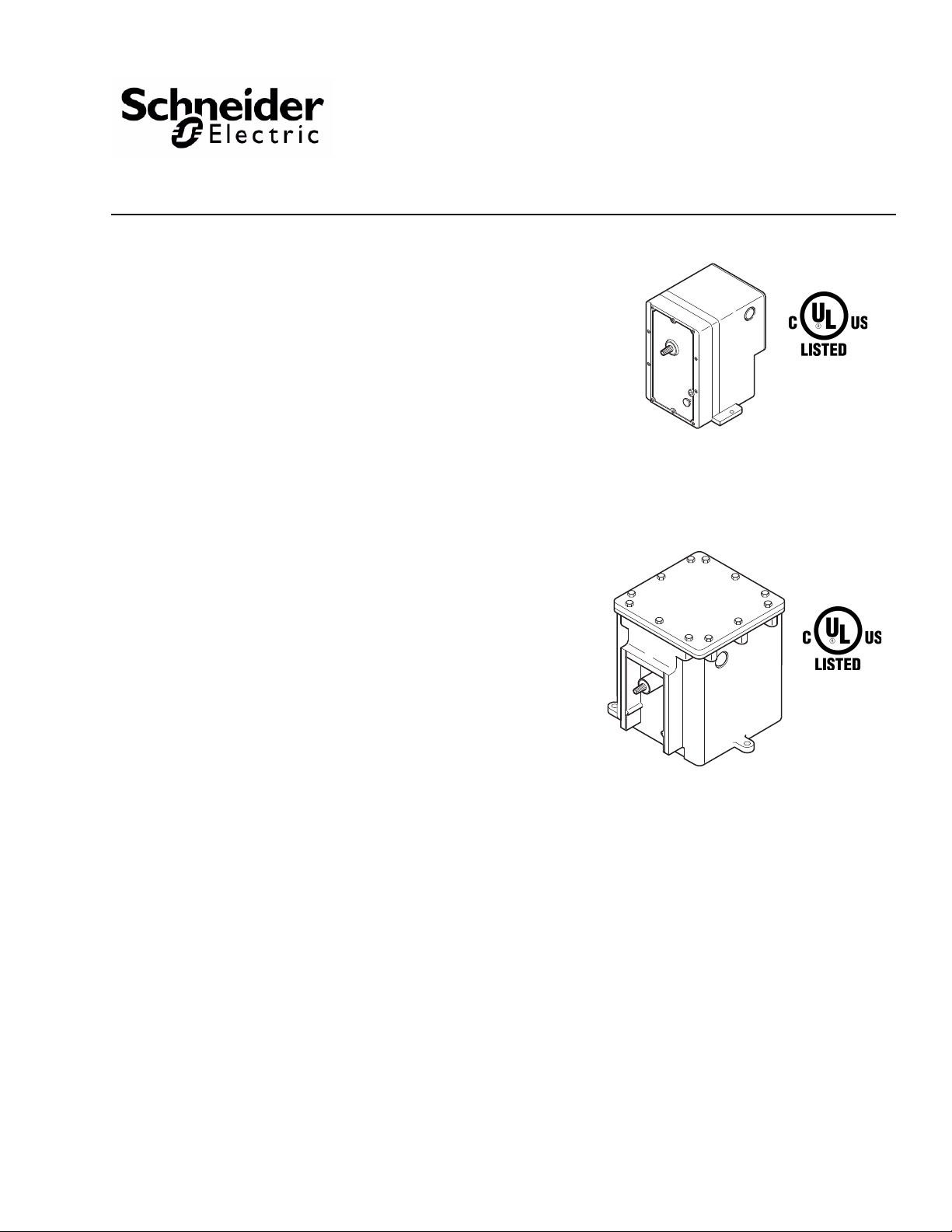
Application
MA6-3xx, MA6-4xx, MA7-4xx,
MA8-3xx, MA8-4xx
(Hazardous Locations)
MA-3xx, MA5-318,
MA-4xx, MA5-419
(Standard)
For two-position operation of dampers, valves, and
other equipment which require the return to normal
position upon power interruption.
Hazardous location models offer a sturdy cast
aluminum case with bolted cover. They have two 3/4"
pipe tapped openings for joint s with rigid metal conduit.
All wiring is brought out to separate termin als for ea se
of installation. These factory enclosure and actuator
assemblies are Underwriters Laboratories listed.
MAx-305 & MAx-318 Series
MAx-405 Through MAx-419
Series
Two-Position Actuators
General Instructions
Features
• Compatible with most SPST control devices
• Spring return
• 24, 120, 208, and 240 Vac models
• Actuators with part number suffix "-500" are
equipped w
ith SPDT auxiliary
switch
• Actuator has a rugged die cast aluminum housing
with
two 1/2” conduit openings
• Hazardous location actuator housing has two 3/4"
p
ipe taped openings for rigid metal cond
con
nection
• Oil immersed motor and gear train
uit
Applicable Literature
• Electric/Electronic Products Catalog, F-27382
• Valve Products Catalog, F-27384
• Cross-Reference Guide, F-26789
• Material Safety Data Sheet (MSDS) for BCS-51-185
Oil (Until Mar
MAx
-4xx-x-x-3)
ch 2002) (MAx-3xx-x-x-3 an
d
• AV -29x V alve Linkage for Hazard ous Location Gear
T
rain Actuators General Instructions, F-27441.
• Apparatus for Hazardous Locations EN-56-2,
F-
18451.
• AV-390 Series, Valve Linkage for Gear Train
Actu
• Material Safety Data Sheet (MSDS) for BCS-51-168
Printed in U.S.A. 6/12 © Copyright 2012 Schneider Electric All Rights Reserved. F-06491-32
ators General Instructions, F-24376.
Oil (
Until Feb. 1989)
• Material Safety Data Sheet (MSDS) for
BCS-
51-185-1 Oil (Current) (MAx-3xx-x-x-4 an
MAx
-4xx-x-x-4)
• High Temperature Exposure Performance (UL 555S)
MAx-31x-x-x-4, MAx-41x-x-x-4 Series Actuator
En
gineering Information EN-216, F-27068
d
s

SPECIFICATIONS
Actuator Inputs
Connections: Coded screw terminals.
Control Circuit: Two-wire.
Power Input: See Table-1.
Actuator Outputs
Torque: See Table-1.
Shaft Rotation:
MA-305, MA-405, MA6-305, MA6-405, CW 180° when power is applied.
MA-318, MA-41x, MAx-318, MAx-41x, CW 180° when power is applied.
Spring Return: CCW to the original position when the actuator is de-energized.
Auxiliary Switch (-500 Models): SPDT makes (or breaks) the circuit at the powered end of
stroke.
Environment
Ambient Temperature Limits:
Shipping & Storage, -40 to 136 °F (-40 to 58 °C).
Operating, -40 to 136 °F (-40 to 58 °C).
Humidity: 5 to 95% RH, non-condensing.
Location: NEMA Type 4 when used with the gasket (provided) and water-tight conduit
connectors (not provided), optional hazardous location models.
Agency Listings:
US Standard UL 873, Underwriters Laboratories (File #E9429 XAPX, Temperature
Indicating and Regulating Equipment).
Candadian Standard C22.2 No. 24: Underwriters Laboratories (File #E429 Category
XAPX7, Temperature Indicating and Regulating Equipment).
Hazardous Location Models, UL file #E29291. Designed for use in hazardous locations
N.E.C., Class 1, Groups C and D, and Class 2, Groups E, F , and G. Temperature code T6 for
hazardous housing.
T able-1 Model Chart.
Power
Part Number
MA-305
MA-305-500 Yes
MA-405
MA-405-500 Yes
MA-318
MA-318-500 Yes
MA-416
MA-416-500 Yes
MA-418
MA-418-500 Yes
MA-419
MA-419-500 Yes
MA5-419
MA5-419-500 Yes
a 4.4 FLA, 26.4 LRA @ 24 or 120 Vac; 2.4 FLA, 13.2 LRA @ 240 Vac.
b Spring return timing with full load opposing spring is approximately 60 sec.
Supply Auxiliary
60
60
50
Switch
No
No
No
No
No
No
No
Vac Hz Running Holding
24
120
24
208
120
240
a
Input
Watts
25
70
Running
25
Holding
56 56
48 48
92 32
104 38
108 42
120 39
VA Rated
Torque
lb-in. (N-m)
16 (1.8)
60 (6.8)
No Load
Timing in
Seconds at
75 °F (24 °C)
20
Mounting Application
b
Any Position
(Horizontal
Output Shaft
Position
Preferred)
Output Shaft
Must Be
Horizontal
Damper
Actuators
Damper
and Valve
Actuators
2 © Copyright 2012 Schneider Electric All Rights Reserved. F-06491-32

Table-2 Actuator Part Numbers for Hazardous Location Applications.
Standard
Part Numbers
Hazardous Location Actuator Assemblies
Part Numbers
a
b c d
Damper Actuators Valve Actuators
MA-305 MA6-305 —
MA-305-500 — —
MA-405 MA6-405 —
MA-405-500 MA6-405-500 —
MA-318 MA6-318 MA8-318
MA-318-500 MA6-318-500 MA8-318-500
MA-416 MA6-416 —
MA-416-500 MA6-416-500 —
MA-418 MA6-418 MA8-418
MA-418-500 MA6-418-500 MA8-418-500
MA-419 MA6-419 —
MA-419-500 MA6-419-500 —
MA5-419 MA7-419 —
MA5-419-500 MA7-419-500 —
a
MAx-31x-x-x-4 and MAx-41x-x-x-4 series actuators provide significantly improved high temperature exposure
performance for use in smoke or fire dampers, or combination smoke and fire dampers. Refer to Engineering
Information EN-216 (UL 555S), F-27068.
b
Class 1, Groups C & D, and Class 2, Groups E, F, and G hazardous locations; refer to EN-56-2.
c
Models for hazardous locations are only available as factory-built enclosure/actuator assemblies.
d
See standard actuator part number wiring diagrams for wiring terminations.
ACCESSORIES
Damper Only
AM-111 Crank arm for 5/16" diameter damper shaft
AM-112 Crank arm for 3/8" diameter damper shaft
AM-113 Crank arm for 1/2" diameter damper shaft
AM-115 Crank arm for 7/16" diameter damper shaft
AM-122 Linkage connector straight type
AM-123 Damper clip
AM-125 5/16" diameter x 20" damper rod
AM-125-048 5/16" diameter x 48" damper rod
AM-132 Ball joint connector
AM-161 Damper linkage kit
AM-161-1 Damper linkage kit
AM-301 90° mounting bracket (not used with MA6-xxx, MA7-xxx, & MA8-xxx)
Valve Only (To be used with 60 lb-in. (6.8 N-m) actuators only, excluding MA7-xxx & MA8-xxx)
AV-29 & AV-300 Linkage for 2-1/2" & 3" discontinued VB-9323
AV-391 Linkage for 1/2" to 2" VB-7xxx and 1/2" to 1-1/4" discontinued VB-9xxx
AV-392 Linkage for 1-1/2" and 2” discontinued VB-9xxx
AV-395 Linkage for 2-1/2" to 4" VB-931x or discontinued VB-92xx
Valve Only (To be used with 60 lb-in. (6.8 N-m) MA7-xxx & MA8-xxx hazardous location actuators
only)
AV-291 Linkage for 1/2" to 2" VB-7xxx valves assembled with hazardous location actuator
assemblies.
AV-295 Linkage for 2-1/2" and 3" VB-9xxx valves assembled with hazardous location actuator
assemblies.
F-06491-32 © Copyright 2012 Schneider Electric All Rights Reserved. 3

TYPICAL APPLICATIONS (Wiring Diagrams)
3
2
4
MA-318, MA-416
MA-418, MA-419
Series Actuator
1 Actuator rotates 180° CW when thermostat or switch contacts are closed.
Actuator spring returns when thermostat or switch contacts are open.
2 High Input (Running)
3 Low Input (Holding)
4 Aux. Switch for -500 Models
NO
NC
Thermostat
or Switch
L1 or H
L2 or G
1
NC
NO
COM
Thermostat
L1 or H
L2 or G
1 Actuator rotates 180° CW when thermostat or switch contacts are closed.
Actuator spring returns when thermostat or switch contacts are open.
2 Aux. Switch for -500 Models
or Switch
Figure-1 Typical Wiring for MA-305 and MA-405 Series.
MA-305
MA-405
1
Series Actuator
Motor
Field Coil
COM
2
NC
NO
Figure-2 Typical Wiring for MA-318, MA-416, MA-418, and MA-419 Series.
4 © Copyright 2012 Schneider Electric All Rights Reserved. F-06491-32

INSTALLATION
Inspection Inspect the package for damage. If damaged, notify the appropriate carrier immediately.
If undamaged, open the package and inspect the device for obvious damage. Return damaged
products.
Requirements • Job wiring diagrams
• Tools (not provided):
– Digital Volt-ohm Meter (DVM)
– Appropriate screwdriver(s) for cover and mounting screws
– Appropriate drill and drill bit for mounting screws
– Appropriate wrenches for adjustment of damper and valve linkages
• Appropriate accessories
• Mounting screws (not provided)
• Training: Installer must be a qualified, experienced technician
Warning:
• Disconnect the power supply (line power) before installation to prevent electrical shock and
equipment damage.
• Make all connections in accordance with the wiring diagram and in accordance with
national and local electrical codes. Use copper conductors only.
Caution:
• Do not apply power to the unit unless the damper linkag e and/or the valve assembly have
been installed.
• Avoid locations where excessive oil, dust, moisture, corrosive fumes or vibration, or an
explosive atmosphere is present. The actuator case is intended primarily to provide a
degree of protection against windblown dust, rain, sleet, and external ice formation (NEMA
Type 4).
Mounting Mount the actuator according to the following requirements:
1. Allow a minimum of 6
compartment.
2. Locate the actuator in a weather-protected area.
3. To ensure water and weather resistance, install the cover gasket (provided) and use
water-tight conduit fittings.
Dampers
Install the actuator and the damper linkage, so that 180° of actuator shaft rotation drives 90° of
damper shaft rotation, as follows:
Actuator Mounting and Damper Linkage Installation
1. Mount the actuator in an appropriate position near the damper.
Note:
• MA-305 and MA-405 series actuators are not position-sensitive, and in damper applications,
may be mounted in any position. However, the upright position is preferred.
• MA-318, MA-416, MA-418, and MA-419 series actuators must be mounted so that the
output shaft lies in a horizontal position.
• To the extent possible, position the actuator to optimize the length of the damper rod
needed to link it with the damper. A damper rod that is too long is not rigid enough for good
control, and a damper rod that is too short makes it difficult to adjust the linkage.
2. Install crank arms onto the driven shaft and the actuator shaft. Tighten the crank arm on the
driven shaft. Do not tight en t he cr an k ar m on the actuator shaft at this time.
3. Install a linkage connector onto the actuator shaft crank arm, at the prick point. Refer to
(Figure-3) and (Figure-4).
" (152 mm) clearance behind the actuator for access to the wiring
F-06491-32 © Copyright 2012 Schneider Electric All Rights Reserved. 5

Figure-3 Location of Prick Point on Crank Arm.
Prick Point
123
Slot provides adjustment
from 7/8" to 3-1/8".
Actuator
Shaft
0°
0°
90°
180°
Install Connector at
Prick-Point on
Crank Arm
Driven
Shaft
Install Connector at
End of Slot on
Crank Arm
Figure-4 180° Actuator Rotation Driving a Damper Rotation of 90°.
4. Install a linkage connector onto the driven shaft crank arm, at the end of the slot. Refer to
(Figure-4).
5. Install the damper rod in the linkage connectors on both crank arms and tighten the linkage
connector screws finger-tight.
Caution: Never attempt to turn the actuator shaft with a wrench or a crank; this may damage
the actuator.
Linkage Adjustment
1. Verify that the crank arm on the actuator shaft is loose. Rotate, by hand, the crank arm on
the actuator to drive the linkage and the damper shaft through its full stroke, to ensure proper
damper action.
2. For normally closed dampers, proceed as follows:
a. Return the damper to the closed position.
b. Tighten the crank arm on the actuator shaft.
c. Loosen the screw on one of the linkage connectors.
d. While pushing the damper closed, tighten the linkage connector screws to secure the
damper rod.
3. For normally open dampers, proceed as follows:
a. Move the damper to approximately 85° of the full open position.
b. Tighten the crank arm on the actuator shaft.
c. Tighten the linkage connector screws to secure the damper rod.
4. Run the actuator back and forth through its full stroke and check for proper damper and
linkage operation. Adjust the linkage if required.
6 © Copyright 2012 Schneider Electric All Rights Reserved. F-06491-32
Caution: When linking an actuator to a damper, be sure that it can complete its full stroke. If
the damper stops the actuator before it has reached its electrical limit of travel on the power
stroke, the actuator may be permanently damaged. Readjust the linkage as necessary.

Valves
Note:
When mounting an actuator onto a valve, observe the following:
• Allow 3" (76 mm) of clearance above the assembled actuator and valve for the removal and
reattachment of the actuator.
• Always install single-seat valves with pressure under the seat.
• Install all two-way valves so that they close against the flow. A tag or an arrow on the valve
body indicates proper flow direction.
• Always install three-way mixing valves with two inlets and one outlet.
• Always install three-way diverting valves with one inlet and two outlets.
• For steam applications only, mount the actuator above the valve body at 45° from the
vertical.
• MA-318, MA-416, MA-418, and MA-419 series actuators can be mounted in any upright
position above the centerline of the valve body. However, the output shaft must lie in a
horizontal position.
Indicator Screw
Indicator
Front Cover
For detailed valve linkage installation instructions, refer to
Hazardous Location Gear Train Actuators General Instructions, F-27441 or
AV-29x Valve Linkage for
AV-390
Series, Valve Linkage for Gear Train Actua to rs Ge neral Instructions, F-24376.
Refer to Figure-5 for the components of a typical valve installation of a standard actuator. For
installing an actuator with a hazardous location housing, refer to Figure-6.
Nylon Bushing
Plunger Assembly
Plunger Cam
Actuator
1
"C" Ring
Mounting Screws (3)
Mounting Bracket
Stem Extension
2
Cover Screws (2)
Stem Locknut
Packing Nut
Mounting Nut
Connecting Pin
1
1
Valve Body
(VB-7XXX Shown)
1 Not included in AV Kits.
2 Used with 1/2" through 2" valve bodies.
1
Figure-5 Typical Components for Valve Installation of Standard Actuator.
F-06491-32 © Copyright 2012 Schneider Electric All Rights Reserved. 7

Indicator Screw
Front Cover
Nylon Bushing
Actuator
Mounting Screws (3)
Mounting Bracket
Valve Body
(VB-7XXX Shown)
Plunger Assembly
Connecting Pin
Stem Extension
Stem Locknut
Packing Nut
Mounting Nut
Cover Screws (2)
Indicator
Plunger Cam
1
1
1 Not included in the Linkage Kit.
2 Mounting screws attach the bracket to
threaded mounting holes in the bottom of
the hazardous location housing.
2
1
1
Figure-6 Typical Components for Valve Installation of Hazardous Location Actuator.
8 © Copyright 2012 Schneider Electric All Rights Reserved. F-06491-32

WIRING
k
A
Hazardous Location Models
Make all electrical connections to the assembly in accordance with the job wiring diagram, the
National Electric Code Article 500, and in compliance with the local electrical codes.
Two 3/ 4" pipe tapped openings are provided in the housing for rigid conduit connections. It is
recommended to insert a chase nipple from inside of the housing to prevent threads from cutting
or damaging wiring.
When wiring, take care to lay all leads in the wiring channel located just under the housing cover
to protect the leads from any sharp edges which may be in the vicinity.
The housing and the edge of the cover are stamped with the letter "O." When replacing the cover,
the letters must be aligned with each other.
Warning: The cover-to-housing orientation must be maintained in order to preserve the
integrity of the seal. Failure to observe this warning can result in injury or death.
1. Remove twelve cover screws and cover. Place cover, machined surface up, in a p rotected
location to avoid damage to machined surfaces.
2. Make all wiring connections to actuator taking care to lay all leads in the wiring channel
provided.
3. Before enclosing the actuator, wipe machined surfaces of housing clean with a lint free cloth
and apply one of the UL approved compounds. See Note below.
Warning: Failure to observe these warnings can result in injury or death.
• Do not scrape, scratch, or use abrasives on the machined surfaces.
• Ensure the surfaces are clean.
• Use only the approved compounds listed below.
4. Secure cover tight against the enclosure in the same position before removal with the twelve
screws provided.
Note: Underwriters Laboratories has sanctioned the use of the following compounds on
hazardous location ground joints: Crouse-Hinds type OSL lubricant, Crouse-Hinds type STL
lubricant, or "No-OXID" oil, grade "D."
Two 1/ 2
" conduit knockouts are provided on the actuator case.
Refer to Figure-7 for terminal locations.
Power Terminals
L 2
ux. Switch
(-500 Models)
Case Ground
N.O.
(Shown with Back Cover Removed)
L 1
C
N.C.
Feed-Through
Terminal Bloc
Figure-7 Actuator Terminal Locations.
F-06491-32 © Copyright 2012 Schneider Electric All Rights Reserved. 9
Refer to Table-3 for the selection of the proper gage wire for the length of the wire run.

CHECKOUT
Table-3 Power Wire Selection.
Actuator Series
MA-305
MA-405 14 2800 (853)
MA-318
MA-416, MA-418, MA-419
a Each run has two wires.
b The length given is for a maximum two-wire run, for one actuator. When multiple actuators are used, determine the
maximum run for each actuator by dividing the number of actuators into the corresponding maximum run.
Wire Size
AWG
14 122 (37)
12 191 (58)
10 305 (93)
14 44 (13)
12 68 (21)
10 110 (34)
14 950 (290)
12 1580 (482)
Maximum Run
ft (m)
a b
After the entire system has been installed and the actuator has been powered up, perform the
following check for proper system operation. Check for the correct operation of the damper while
the actuator is being stroked.
Note: Smoke control systems must be tested in accordance with NFPA Standard 92A.
1. Verify that the system wiring is properly connected and powered.
2. Be sure the controller (manual or automatic) is operating properly according to system
requirements.
3. When the controller energizes the actuator, the output shaft must run to the end of the stroke
(180° CW).
4. When the controller de-energizes the actuator, the spring will return the output shaft to its
original position.
5. The action of the auxiliary switch (-500 models only) shall be as follows:
a. C makes to N.C. when the actuator is de-energized. Refer to (Figure-8).
b. C makes to N.O. when the actuator is energized and the output shaft reaches the end
of the stroke.
N.C. (Normally Closed)
C (Common)
N.O. (Normally Open)
N.O. makes when actuator is energized and
output shaft reaches end of stroke.
Figure-8 Action of Auxiliary Switch (-500 Models Only).
THEORY OF OPERATION
MA-305 and MA-405 series actuator output shafts rotate 180° clockwise when energized and
spring return counterclockwise to 0° when de-energized.
MA-31x and MA-41x series actuator output shafts rotate 170° clockwise when energized and
spring return counterclockwise when de-energized.
MA-305 and MA-405 series actuator motors are assembled to a gear train and stall at the end of
the power stroke.
MA-318, MA-416, MA-418, and MA-419 series actuators have an end of travel switch which
reduces the running input from 70 watts to 25 watts at the end of clockwise shaft rotation.
10 © Copyright 2012 Schneider Electric All Rights Reserved. F-06491-32

MAINTENANCE
1/4 (6)
4-3/4 (121)
15/16 (24)
3-3/8
(86)
4-1/2
(114)
1-1/2
(38)
2-1/4
(57)
4-1/4 (108)
5-5/8 (143)
3-7/8
(98)
4 (102)
5-3/4
(146)
5-3/8 (136)
1-7/16 (37)
4-3/4
(121)
1/2 (13)
Dia. Shaft
17/64 (7)
Dia. Hole
(1 of 3)
Dimensions are in inches (mm).
1/2 (13) Conduit
Opening on Each Side
13/16 (21)
FIELD REPAIR
DIMENSIONAL DATA
Caution: MA-300 series and MA-400 series actuators that are used in applications where they
are energized for extended periods of time must be electrically cycled at least once every six
months to ensure correct operation.
Regular maintenance of the total system is recommended to assure sustained, optimum
performance.
None. Replace an inoperative actuator with a functional unit.
Figure-9 Dimensions of MA-3xx, MA5-318, MA-4xx, and MA5-419 (Standard) Actua tors.
F-06491-32 © Copyright 2012 Schneider Electric All Rights Reserved. 11

Figure-10 Dimensions of MA6-3xx, MA6-4xx, and MA7-4xx Damper Actuators for Hazardous Locations.
4-1/2
(114)
15/16
(24)
4-7/32
(107)
8-1/4
(209)
1/2 (13)
Dia. Shaft
Dimensions are in inches (mm).
4-13/32
(112)
9
(228)
1/4 (6)
2-15/16
(51)
2-1/8
(54)
3/4 (19) Pipe Tap
On Each Side
9
(229)
9-9/16
(243)
10-5/8
(270)
3-1/16
(78)
6-1/8
(156)
7-1/2
(190)
21/64 (8)
Dia. Hole
(1 of 3)
3-3/4
(95)
2-1/8
(54)
10-13/16
(275)
9
4-1/2
(114)
(229)
2-1/8
(54)
1/8
(228)
(3)
1/4 (6)
9
Figure-11 Dimensions of MA7-4xx, MA8-3xx, and MA8-4xx Valve Actuators for Hazardous Locations.
© Copyright 2012, Schneider Electric
All brand names, trademarks and registered
trademarks are the property of their respective
owners. Information contained within this
document is subject to change without notice.
F-06491-32
3/4 (19) Pipe Tap
On Each Side
2-15/16
(51)
Dimensions are in inches (mm).
7
(178)
4-13/32
(112)
4-1/4
(108)
8-1/4
(209)
 Loading...