

Page 1
User Manual
KVM Switch
KVM2132P
KVM2116P
KVM1116P
Page 2

Page 3

American Power Conversion Legal Disclaimer
The information presented in this manual is not warranted by the American Power Conversion
Corporation to be authoritative, error free, or complete. This publication is not meant to be a substitute
for a detailed operational and site specific development plan. Therefore, American Power Conversion
Corporation assumes no liability for damages, violations of codes, improper installation, system failures,
or any other problems that could arise based on the use of this Publication.
The information contained in this Publication is provided as is and has been prepared solely for the
purpose of evaluating data center design and construction. This Publication has been compiled in good
faith by American Power Conversion Corporation. However, no representation is made or warranty
given, either express or implied, as to the completeness or accuracy of the information this Publication
contains.
IN NO EVENT SHALL AMERICAN POWER CONVERSION CORPORATION BE LIABLE
FOR ANY DIRECT, INDIRECT, CONSEQUENTIAL, PUNITIVE, SPECIAL, OR
INCIDENTAL DAMAGES (INCLUDING, WITHOUT LIMITATION, DAMAGES FOR LOSS
OF BUSINESS, CONTRACT, REVENUE, DATA, INFORMATION, OR BUSINESS
INTERRUPTION) RESULTING FROM, ARISING OUT, OR IN CONNECTION WITH THE
USE OF, OR INABILITY TO USE THIS PUBLICATION OR THE CONTENT, EVEN IF
AMERICAN POWER CONVERSION CORPORATION HAS BEEN EXPRESSLY ADVISED
OF THE POSSIBILITY OF SUCH DAMAGES. AMERICAN POWER CONVERSION
CORPORATION RESERVES THE RIGHT TO MAKE CHANGES OR UPDATES WITH
RESPECT TO OR IN THE CONTENT OF THE PUBLICATION OR THE FORMAT
THEREOF AT ANY TIME WITHOUT NOTICE.
Copyright, intellectual, and all other proprietary rights in the content (including but not limited to
software, audio, video, text, and photographs) rests with American Power Conversion Corporation or its
licensors. All rights in the content not expressly granted herein are reserved. No rights of any kind are
licensed or assigned or shall otherwise pass to persons accessing this information.
This Publication shall not be for resale in whole or in part.
Page 4

Page 5

Contents
General Information........................................................ 1
Overview . . . . . . . . . . . . . . . . . . . . . . . . . . . . . . . . . . . . . . . . . . . . . . . . 1
KVM2132P / KVM2116P / KVM1116P KVM Switches . . . . . . . . . . . . 1
KVM2132P / KVM2116P KVM Switches only . . . . . . . . . . . . . . . . . . 2
Safety . . . . . . . . . . . . . . . . . . . . . . . . . . . . . . . . . . . . . . . . . . . . . . . . . . . 2
Taking Delivery . . . . . . . . . . . . . . . . . . . . . . . . . . . . . . . . . . . . . . . . . . . 3
Inventory . . . . . . . . . . . . . . . . . . . . . . . . . . . . . . . . . . . . . . . . . . . . . . . 3
System Requirements . . . . . . . . . . . . . . . . . . . . . . . . . . . . . . . . . . . . .4
Remote User Computers . . . . . . . . . . . . . . . . . . . . . . . . . . . . . . . . . . 4
Servers . . . . . . . . . . . . . . . . . . . . . . . . . . . . . . . . . . . . . . . . . . . . . . . . . 4
Video . . . . . . . . . . . . . . . . . . . . . . . . . . . . . . . . . . . . . . . . . . . . . . . . . . 4
KVM Server Modules and cables . . . . . . . . . . . . . . . . . . . . . . . . . . . 5
Supported Operating Systems . . . . . . . . . . . . . . . . . . . . . . . . . . . . . 5
Browsers . . . . . . . . . . . . . . . . . . . . . . . . . . . . . . . . . . . . . . . . . . . . . . . 5
Max Server connections . . . . . . . . . . . . . . . . . . . . . . . . . . . . . . . . . . 6
Components . . . . . . . . . . . . . . . . . . . . . . . . . . . . . . . . . . . . . . . . . . . . . 7
Installation ....................................................................... 9
Overview . . . . . . . . . . . . . . . . . . . . . . . . . . . . . . . . . . . . . . . . . . . . . . . . 9
Rack Mounting . . . . . . . . . . . . . . . . . . . . . . . . . . . . . . . . . . . . . . . . . . .9
Rack Mounting - Front . . . . . . . . . . . . . . . . . . . . . . . . . . . . . . . . . . . . 9
Rack Mounting - Rear . . . . . . . . . . . . . . . . . . . . . . . . . . . . . . . . . . . 10
Optional KVM to LCD Console Mounting . . . . . . . . . . . . . . . . . . . . .10
Single Level Installation . . . . . . . . . . . . . . . . . . . . . . . . . . . . . . . . . . . 11
KVM1116P Single Level Installation Diagram . . . . . . . . . . . . . . . . 11
KVM2132P Single Level Installation Diagram . . . . . . . . . . . . . . . . 12
Tiering Multiple KVM Switches . . . . . . . . . . . . . . . . . . . . . . . . . . . . . 13
KVM1116P Two Level Installation . . . . . . . . . . . . . . . . . . . . . . . . . . 13
Two Level Installation Diagram . . . . . . . . . . . . . . . . . . . . . . . . . . . . 13
Three Level Installation and (1 or 2) Bus Configurations . . . . . . . 14
KVM2132P / KVM2116P Two busTiered Diagram . . . . . . . . . . . . . 14
KVM1116P One Bus Tiered Diagram . . . . . . . . . . . . . . . . . . . . . . . 15
KVM Switch KVM2132P, KVM2116P, KVM1116P User Manual
i
Page 6

Hardware Setup . . . . . . . . . . . . . . . . . . . . . . . . . . . . . . . . . . . . . . . . . 15
Cable Length Considerations . . . . . . . . . . . . . . . . . . . . . . . . . . . . . . 15
Hot Plugging . . . . . . . . . . . . . . . . . . . . . . . . . . . . . . . . . . . . . . . . . . . 15
The Adapter ID Function . . . . . . . . . . . . . . . . . . . . . . . . . . . . . . . . . 16
Powering Off and Restarting . . . . . . . . . . . . . . . . . . . . . . . . . . . . . . 16
Port ID Numbering . . . . . . . . . . . . . . . . . . . . . . . . . . . . . . . . . . . . . . . 16
Port Selection . . . . . . . . . . . . . . . . . . . . . . . . . . . . . . . . . . . . . . . . . . 16
PDU Connection (KVM2132P, KVM2116P) . . . . . . . . . . . . . . . . . . . 16
Super Administrator Setup........................................... 17
Overview . . . . . . . . . . . . . . . . . . . . . . . . . . . . . . . . . . . . . . . . . . . . . . . 17
First Time Setup . . . . . . . . . . . . . . . . . . . . . . . . . . . . . . . . . . . . . . . . 17
Network Setup . . . . . . . . . . . . . . . . . . . . . . . . . . . . . . . . . . . . . . . . . . 17
Changing the Super Administrator Login . . . . . . . . . . . . . . . . . . . 17
Logging In ...................................................................... 19
Overview . . . . . . . . . . . . . . . . . . . . . . . . . . . . . . . . . . . . . . . . . . . . . . . 19
Local Console Login . . . . . . . . . . . . . . . . . . . . . . . . . . . . . . . . . . . . . 19
Browser Login. . . . . . . . . . . . . . . . . . . . . . . . . . . . . . . . . . . . . . . . . . . 19
Windows Client AP Login . . . . . . . . . . . . . . . . . . . . . . . . . . . . . . . . . 20
Connect using Windows Client AP . . . . . . . . . . . . . . . . . . . . . . . . . 20
The File Menu . . . . . . . . . . . . . . . . . . . . . . . . . . . . . . . . . . . . . . . . . . . 20
Java Client AP Login . . . . . . . . . . . . . . . . . . . . . . . . . . . . . . . . . . . . . 21
Connect using - Java Client AP . . . . . . . . . . . . . . . . . . . . . . . . . . . . 21
The User Interface ......................................................... 22
Overview . . . . . . . . . . . . . . . . . . . . . . . . . . . . . . . . . . . . . . . . . . . . . . . 22
The Web Browser Main Page . . . . . . . . . . . . . . . . . . . . . . . . . . . . . . 22
The Tab Bar . . . . . . . . . . . . . . . . . . . . . . . . . . . . . . . . . . . . . . . . . . . . 23
The AP GUI Main Page . . . . . . . . . . . . . . . . . . . . . . . . . . . . . . . . . . . 23
The Local Console GUI Main Page . . . . . . . . . . . . . . . . . . . . . . . . . . 24
ii
KVM Switch KVM2132P, KVM2116P, KVM1116P User Manual
Page 7

The Control Panel . . . . . . . . . . . . . . . . . . . . . . . . . . . . . . . . . . . . . . . .24
WinClient Control Panel Functions . . . . . . . . . . . . . . . . . . . . . . . . . 26
Macros . . . . . . . . . . . . . . . . . . . . . . . . . . . . . . . . . . . . . . . . . . . . . . . . 27
Video Settings . . . . . . . . . . . . . . . . . . . . . . . . . . . . . . . . . . . . . . . . . . 30
The Message Board . . . . . . . . . . . . . . . . . . . . . . . . . . . . . . . . . . . . . 31
Virtual Media . . . . . . . . . . . . . . . . . . . . . . . . . . . . . . . . . . . . . . . . . . . 32
Zoom . . . . . . . . . . . . . . . . . . . . . . . . . . . . . . . . . . . . . . . . . . . . . . . . . 33
The On-Screen Keyboard . . . . . . . . . . . . . . . . . . . . . . . . . . . . . . . . . 33
Mouse Pointer Type . . . . . . . . . . . . . . . . . . . . . . . . . . . . . . . . . . . . . 34
Mouse DynaSync Mode . . . . . . . . . . . . . . . . . . . . . . . . . . . . . . . . . . 34
Control Panel Configuration . . . . . . . . . . . . . . . . . . . . . . . . . . . . . . 35
The Java Control Panel . . . . . . . . . . . . . . . . . . . . . . . . . . . . . . . . . . . 36
Port Access ...................................................................37
Overview. . . . . . . . . . . . . . . . . . . . . . . . . . . . . . . . . . . . . . . . . . . . . . . .37
The Sidebar . . . . . . . . . . . . . . . . . . . . . . . . . . . . . . . . . . . . . . . . . . . . .38
The Sidebar Tree Structure . . . . . . . . . . . . . . . . . . . . . . . . . . . . . . . . 38
Sidebar Utilities . . . . . . . . . . . . . . . . . . . . . . . . . . . . . . . . . . . . . . . . . 38
Port and Outlet Naming . . . . . . . . . . . . . . . . . . . . . . . . . . . . . . . . . . . 39
Scan . . . . . . . . . . . . . . . . . . . . . . . . . . . . . . . . . . . . . . . . . . . . . . . . . . 40
Array . . . . . . . . . . . . . . . . . . . . . . . . . . . . . . . . . . . . . . . . . . . . . . . . . . 40
Filter . . . . . . . . . . . . . . . . . . . . . . . . . . . . . . . . . . . . . . . . . . . . . . . . . . 40
KVM Devices and Ports - Connections Page . . . . . . . . . . . . . . . . . .40
Device Level . . . . . . . . . . . . . . . . . . . . . . . . . . . . . . . . . . . . . . . . . . . . 40
Port Level . . . . . . . . . . . . . . . . . . . . . . . . . . . . . . . . . . . . . . . . . . . . . . 41
PDU Devices - Device Monitor Page . . . . . . . . . . . . . . . . . . . . . . . . .42
The Main Panel - Group View . . . . . . . . . . . . . . . . . . . . . . . . . . . . . . 44
Outlet Settings . . . . . . . . . . . . . . . . . . . . . . . . . . . . . . . . . . . . . . . . . . 45
Adding a PDU in the KVM GUI main page . . . . . . . . . . . . . . . . . . . . 46
History . . . . . . . . . . . . . . . . . . . . . . . . . . . . . . . . . . . . . . . . . . . . . . . . .49
Favorites. . . . . . . . . . . . . . . . . . . . . . . . . . . . . . . . . . . . . . . . . . . . . . . .49
User Preferences. . . . . . . . . . . . . . . . . . . . . . . . . . . . . . . . . . . . . . . . .51
Sessions. . . . . . . . . . . . . . . . . . . . . . . . . . . . . . . . . . . . . . . . . . . . . . . .52
Access . . . . . . . . . . . . . . . . . . . . . . . . . . . . . . . . . . . . . . . . . . . . . . . . .53
Device Level Browser GUI Interface . . . . . . . . . . . . . . . . . . . . . . . . 53
Port Level Browser GUI Interface . . . . . . . . . . . . . . . . . . . . . . . . . . . 54
Device Level AP GUI Interface . . . . . . . . . . . . . . . . . . . . . . . . . . . . . 54
Port Level AP GUI Interface . . . . . . . . . . . . . . . . . . . . . . . . . . . . . . . 54
KVM Switch KVM2132P, KVM2116P, KVM1116P User Manual
iii
Page 8

Port Configuration . . . . . . . . . . . . . . . . . . . . . . . . . . . . . . . . . . . . . . . 55
Device Level . . . . . . . . . . . . . . . . . . . . . . . . . . . . . . . . . . . . . . . . . . . . 55
Port Level . . . . . . . . . . . . . . . . . . . . . . . . . . . . . . . . . . . . . . . . . . . . . . 55
Port Properties . . . . . . . . . . . . . . . . . . . . . . . . . . . . . . . . . . . . . . . . . . 55
Associated Links . . . . . . . . . . . . . . . . . . . . . . . . . . . . . . . . . . . . . . . . 55
Power Management . . . . . . . . . . . . . . . . . . . . . . . . . . . . . . . . . . . . . . 56
Adding and Removing Associations . . . . . . . . . . . . . . . . . . . . . . . . 56
Configuration . . . . . . . . . . . . . . . . . . . . . . . . . . . . . . . . . . . . . . . . . . . 57
Synchronization . . . . . . . . . . . . . . . . . . . . . . . . . . . . . . . . . . . . . . . . . 58
User Management.......................................................... 59
Overview . . . . . . . . . . . . . . . . . . . . . . . . . . . . . . . . . . . . . . . . . . . . . . . 59
Users . . . . . . . . . . . . . . . . . . . . . . . . . . . . . . . . . . . . . . . . . . . . . . . . . . 59
Adding Users . . . . . . . . . . . . . . . . . . . . . . . . . . . . . . . . . . . . . . . . . . . 60
Modifying User Accounts . . . . . . . . . . . . . . . . . . . . . . . . . . . . . . . . . 61
Deleting User Accounts . . . . . . . . . . . . . . . . . . . . . . . . . . . . . . . . . . 61
Groups. . . . . . . . . . . . . . . . . . . . . . . . . . . . . . . . . . . . . . . . . . . . . . . . . 62
Creating Groups . . . . . . . . . . . . . . . . . . . . . . . . . . . . . . . . . . . . . . . . 62
Modifying Groups . . . . . . . . . . . . . . . . . . . . . . . . . . . . . . . . . . . . . . . 62
Deleting Groups . . . . . . . . . . . . . . . . . . . . . . . . . . . . . . . . . . . . . . . . . 62
Users and Groups. . . . . . . . . . . . . . . . . . . . . . . . . . . . . . . . . . . . . . . . 63
Assigning Users to a Group From the User's Notebook . . . . . . . . 63
Removing Users From a Group in the User's Notebook . . . . . . . . 64
Assigning Users to a Group From the Group's Notebook . . . . . . 64
Removing Users From a Group From the Group's Notebook . . . . 64
Device Assignment. . . . . . . . . . . . . . . . . . . . . . . . . . . . . . . . . . . . . . . 64
Assigning Device Permissions From the User's Notebook . . . . . 65
Assigning Device Permissions From the Groups' Notebook . . . . 66
iv
KVM Switch KVM2132P, KVM2116P, KVM1116P User Manual
Page 9

Device Management ......................................................67
Device Information . . . . . . . . . . . . . . . . . . . . . . . . . . . . . . . . . . . . . . .67
General . . . . . . . . . . . . . . . . . . . . . . . . . . . . . . . . . . . . . . . . . . . . . . . . 67
Environment . . . . . . . . . . . . . . . . . . . . . . . . . . . . . . . . . . . . . . . . . . . . 67
Operating Mode . . . . . . . . . . . . . . . . . . . . . . . . . . . . . . . . . . . . . . . . . 67
Network . . . . . . . . . . . . . . . . . . . . . . . . . . . . . . . . . . . . . . . . . . . . . . . . 68
IPv4 Settings . . . . . . . . . . . . . . . . . . . . . . . . . . . . . . . . . . . . . . . . . . . 69
IPv6 Settings . . . . . . . . . . . . . . . . . . . . . . . . . . . . . . . . . . . . . . . . . . . 70
ANMS . . . . . . . . . . . . . . . . . . . . . . . . . . . . . . . . . . . . . . . . . . . . . . . . . 70
Authentication . . . . . . . . . . . . . . . . . . . . . . . . . . . . . . . . . . . . . . . . . . 71
OOBC . . . . . . . . . . . . . . . . . . . . . . . . . . . . . . . . . . . . . . . . . . . . . . . . . 73
Security . . . . . . . . . . . . . . . . . . . . . . . . . . . . . . . . . . . . . . . . . . . . . . . .75
Login Failures . . . . . . . . . . . . . . . . . . . . . . . . . . . . . . . . . . . . . . . . . . 75
Filter . . . . . . . . . . . . . . . . . . . . . . . . . . . . . . . . . . . . . . . . . . . . . . . . . . 75
Account Policy . . . . . . . . . . . . . . . . . . . . . . . . . . . . . . . . . . . . . . . . . . 76
Encryption . . . . . . . . . . . . . . . . . . . . . . . . . . . . . . . . . . . . . . . . . . . . . 77
Mode . . . . . . . . . . . . . . . . . . . . . . . . . . . . . . . . . . . . . . . . . . . . . . . . . . 77
Private Certificate . . . . . . . . . . . . . . . . . . . . . . . . . . . . . . . . . . . . . . . 78
Certificate Signing Request . . . . . . . . . . . . . . . . . . . . . . . . . . . . . . . 79
Date/Time . . . . . . . . . . . . . . . . . . . . . . . . . . . . . . . . . . . . . . . . . . . . . . 79
PDU Devices . . . . . . . . . . . . . . . . . . . . . . . . . . . . . . . . . . . . . . . . . . . .81
Configuration Page . . . . . . . . . . . . . . . . . . . . . . . . . . . . . . . . . . . . . . 81
Outlet Configuration . . . . . . . . . . . . . . . . . . . . . . . . . . . . . . . . . . . . . 82
Configure Outlet Time Delay . . . . . . . . . . . . . . . . . . . . . . . . . . . . . . . 82
Port Operation................................................................83
Connecting to a Port . . . . . . . . . . . . . . . . . . . . . . . . . . . . . . . . . . . . . .83
Port Toolbar . . . . . . . . . . . . . . . . . . . . . . . . . . . . . . . . . . . . . . . . . . . . .83
Toolbar icons . . . . . . . . . . . . . . . . . . . . . . . . . . . . . . . . . . . . . . . . . . 84
Toolbar Hotkey Port Switching . . . . . . . . . . . . . . . . . . . . . . . . . . . . . 84
Auto Scanning . . . . . . . . . . . . . . . . . . . . . . . . . . . . . . . . . . . . . . . . . . 84
Skip Mode . . . . . . . . . . . . . . . . . . . . . . . . . . . . . . . . . . . . . . . . . . . . . . 85
Recalling the Port Access Page. . . . . . . . . . . . . . . . . . . . . . . . . . . . .85
GUI Hotkey Summary Table . . . . . . . . . . . . . . . . . . . . . . . . . . . . . . . .85
Keyboard Emulation . . . . . . . . . . . . . . . . . . . . . . . . . . . . . . . . . . . . . .86
Mac Keyboard . . . . . . . . . . . . . . . . . . . . . . . . . . . . . . . . . . . . . . . . . . 86
Sun Keyboard . . . . . . . . . . . . . . . . . . . . . . . . . . . . . . . . . . . . . . . . . . . 87
KVM Switch KVM2132P, KVM2116P, KVM1116P User Manual
v
Page 10

Panel Array Mode . . . . . . . . . . . . . . . . . . . . . . . . . . . . . . . . . . . . . . . 88
Panel Array Toolbar . . . . . . . . . . . . . . . . . . . . . . . . . . . . . . . . . . . . . 88
Multiuser Operation . . . . . . . . . . . . . . . . . . . . . . . . . . . . . . . . . . . . . . 89
Users and Buses . . . . . . . . . . . . . . . . . . . . . . . . . . . . . . . . . . . . . . . 89
Log.................................................................................. 90
Log Information . . . . . . . . . . . . . . . . . . . . . . . . . . . . . . . . . . . . . . . . . 90
Log Notification Settings . . . . . . . . . . . . . . . . . . . . . . . . . . . . . . . . . . 91
Maintenance .................................................................. 92
Main Firmware Upgrade. . . . . . . . . . . . . . . . . . . . . . . . . . . . . . . . . . . 92
Adapter Firmware Upgrade . . . . . . . . . . . . . . . . . . . . . . . . . . . . . . . . 92
Firmware Upgrade Recovery . . . . . . . . . . . . . . . . . . . . . . . . . . . . . . . 93
Adapter Firmware Upgrade Recovery . . . . . . . . . . . . . . . . . . . . . . . 93
Backup/Restore . . . . . . . . . . . . . . . . . . . . . . . . . . . . . . . . . . . . . . . . . 93
Backup . . . . . . . . . . . . . . . . . . . . . . . . . . . . . . . . . . . . . . . . . . . . . . . . 93
Restore . . . . . . . . . . . . . . . . . . . . . . . . . . . . . . . . . . . . . . . . . . . . . . . . 93
Ping . . . . . . . . . . . . . . . . . . . . . . . . . . . . . . . . . . . . . . . . . . . . . . . . . . . 94
Restore Values . . . . . . . . . . . . . . . . . . . . . . . . . . . . . . . . . . . . . . . . . . 94
Reset on exit . . . . . . . . . . . . . . . . . . . . . . . . . . . . . . . . . . . . . . . . . . . 94
The Download Tab . . . . . . . . . . . . . . . . . . . . . . . . . . . . . . . . . . . . . . . 94
The Log Server . . . . . . . . . . . . . . . . . . . . . . . . . . . . . . . . . . . . . . . . . . 95
Installation . . . . . . . . . . . . . . . . . . . . . . . . . . . . . . . . . . . . . . . . . . . . . 95
Starting Up . . . . . . . . . . . . . . . . . . . . . . . . . . . . . . . . . . . . . . . . . . . . . 95
The Menu Bar . . . . . . . . . . . . . . . . . . . . . . . . . . . . . . . . . . . . . . . . . . . 95
The Log Server Main Screen . . . . . . . . . . . . . . . . . . . . . . . . . . . . . . 96
LDAP Server Configuration . . . . . . . . . . . . . . . . . . . . . . . . . . . . . . . . 97
Introduction . . . . . . . . . . . . . . . . . . . . . . . . . . . . . . . . . . . . . . . . . . . . 97
Configuring LDAP under Windows 2003 Server. . . . . . . . . . . . . . . 97
OpenLDAP . . . . . . . . . . . . . . . . . . . . . . . . . . . . . . . . . . . . . . . . . . . . 102
Factory Default Settings . . . . . . . . . . . . . . . . . . . . . . . . . . . . . . . . . 103
Serial Adapter Pin Assignments . . . . . . . . . . . . . . . . . . . . . . . . . . . 104
KVM KVM2132P / KVM2116P / KVM1116P . . . . . . . . . . . . . . . . . . 104
vi
KVM Switch KVM2132P, KVM2116P, KVM1116P User Manual
Page 11

Supported KVM Switches . . . . . . . . . . . . . . . . . . . . . . . . . . . . . . . . .104
Supported PDUs . . . . . . . . . . . . . . . . . . . . . . . . . . . . . . . . . . . . . . . .104
KVM2132P / KVM2116P only . . . . . . . . . . . . . . . . . . . . . . . . . . . . . . 104
Virtual Media Support . . . . . . . . . . . . . . . . . . . . . . . . . . . . . . . . . . . .105
WinClient ActiveX Viewer / WinClient AP . . . . . . . . . . . . . . . . . . . 105
Java Applet Viewer / Java Client AP . . . . . . . . . . . . . . . . . . . . . . . 105
IP Address Determination. . . . . . . . . . . . . . . . . . . . . . . . . . . . . . . . .105
IP Installer . . . . . . . . . . . . . . . . . . . . . . . . . . . . . . . . . . . . . . . . . . . . . 105
Browser . . . . . . . . . . . . . . . . . . . . . . . . . . . . . . . . . . . . . . . . . . . . . . . 106
IPv6 . . . . . . . . . . . . . . . . . . . . . . . . . . . . . . . . . . . . . . . . . . . . . . . . . . 106
Port Forwarding . . . . . . . . . . . . . . . . . . . . . . . . . . . . . . . . . . . . . . . 106
PPP Modem Operation . . . . . . . . . . . . . . . . . . . . . . . . . . . . . . . . . . 107
Connection Setup Example (Windows XP) . . . . . . . . . . . . . . . . . . 108
Additional Mouse Synchronization Procedures . . . . . . . . . . . . . 108
Fan Location and Speed Information . . . . . . . . . . . . . . . . . . . . . . .109
KVM2132P / KVM2116P only . . . . . . . . . . . . . . . . . . . . . . . . . . . . . . 109
Fan Location . . . . . . . . . . . . . . . . . . . . . . . . . . . . . . . . . . . . . . . . . . . 109
Fan Speed . . . . . . . . . . . . . . . . . . . . . . . . . . . . . . . . . . . . . . . . . . . . . 109
Temperature Sensor Location and Information . . . . . . . . . . . . . . .109
KVM2132P / KVM2116P only . . . . . . . . . . . . . . . . . . . . . . . . . . . . . . 109
KVM-SERIAL Server Module Configuration and Operation . . . . .109
Configuration . . . . . . . . . . . . . . . . . . . . . . . . . . . . . . . . . . . . . . . . . . 109
Operation . . . . . . . . . . . . . . . . . . . . . . . . . . . . . . . . . . . . . . . . . . . . . 110
Internal Serial Interface Configuration . . . . . . . . . . . . . . . . . . . . . .110
Navigation . . . . . . . . . . . . . . . . . . . . . . . . . . . . . . . . . . . . . . . . . . . . . 110
Operation . . . . . . . . . . . . . . . . . . . . . . . . . . . . . . . . . . . . . . . . . . . . . 111
Switch Level Configuration . . . . . . . . . . . . . . . . . . . . . . . . . . . . . . . 111
Port Level Configuration . . . . . . . . . . . . . . . . . . . . . . . . . . . . . . . . . 111
Trusted Certificates. . . . . . . . . . . . . . . . . . . . . . . . . . . . . . . . . . . . . .112
Overview . . . . . . . . . . . . . . . . . . . . . . . . . . . . . . . . . . . . . . . . . . . . . . 112
Installing the Certificate . . . . . . . . . . . . . . . . . . . . . . . . . . . . . . . . . 112
Self-Signed Private Certificates . . . . . . . . . . . . . . . . . . . . . . . . . . . .112
KVM Switch KVM2132P, KVM2116P, KVM1116P User Manual
vii
Page 12

Troubleshooting .......................................................... 114
General Operation . . . . . . . . . . . . . . . . . . . . . . . . . . . . . . . . . . . . . . 114
Mouse Problems . . . . . . . . . . . . . . . . . . . . . . . . . . . . . . . . . . . . . . . 115
Virtual Media . . . . . . . . . . . . . . . . . . . . . . . . . . . . . . . . . . . . . . . . . . 116
Web Browser . . . . . . . . . . . . . . . . . . . . . . . . . . . . . . . . . . . . . . . . . . 116
The WinClient ActiveX Viewer and the WinClient AP . . . . . . . . . . 116
The Java Applet and Java Client AP . . . . . . . . . . . . . . . . . . . . . . . 118
Sun Systems . . . . . . . . . . . . . . . . . . . . . . . . . . . . . . . . . . . . . . . . . . 118
Mac Systems . . . . . . . . . . . . . . . . . . . . . . . . . . . . . . . . . . . . . . . . . . 118
Redhat Systems . . . . . . . . . . . . . . . . . . . . . . . . . . . . . . . . . . . . . . . . 119
The Log Server . . . . . . . . . . . . . . . . . . . . . . . . . . . . . . . . . . . . . . . . 119
Panel-Array Mode . . . . . . . . . . . . . . . . . . . . . . . . . . . . . . . . . . . . . . 119
Specifications .............................................................. 120
KVM2132P / KVM2116P / KVM1116A . . . . . . . . . . . . . . . . . . . . . . . 120
viii
KVM Switch KVM2132P, KVM2116P, KVM1116P User Manual
Page 13

General Information
Overview
KVM2132P / KVM2116P / KVM1116P KVM Switches
Note: Save these instructions. Read and adhere to all the instructions. All servicing must be
performed by authorized personnel only.
The KVM switch allows local and remote users to monitor and access multiple servers from a single
console. The switch models differ by number of buses and KVM ports.
SKU Bus Support KVM Ports
KVM2132P 1 Local, 2 Remote 32
KVM2116P 1 Local, 2 Remote 16
KVM1116P 1 Local shared with 1Remote 16
• Each bus permits a separate user session so that up to three (KVM2132P or KVM2116P)
concurrent independent connections to the attached servers can take place.
• The switches use TCP/IP communications protocol. They can be accessed by their IP addresses
from anywhere on the LAN, WAN, or Internet. The location of the connecting computer is
irrelevent.
• Remote users log in using a browser or stand-alone Windows or Java GUI applications. Java
allows the switches to work with JRE (Java Runtime Environment) enabled operating systems,
ensuring multi-platform operability.
• The client software allows operators to exchange keyboard, video and mouse signals with the
servers attached to the switches just as if they were working on the equipment directly.
• Up to 32 (KVM2132P)
to communicate with each other to facilitate port sharing.
• Administrators can perform maintenance tasks from installing and running GUI applications, to
BIOS level troubleshooting, routine monitoring, concurrent maintenance, and system
administration.
• Local console operation is accomplished by entering hotkey combinations from the keyboard with
a full screen GUI display.
• The Auto Scan feature permits automatic switching from port to port at user-specified intervals,
while the Panel Array Mode can display the video output of up to 42 servers at the same time.
• CAT 5e cable links the switch to the servers. A 16 or 32 port switch can be installed in a 1U rack,
and use the internal network wiring in most modern commercial buildings.
• The switch receives keyboard input directly. There is no software installation.
• Download firmware updates from www.apc.com.
• Adapter ID function stores port information like the adapter ID, OS, keyboard language, adapter
name, operation modes and more. When a KVM Adapter Cable is moved from one port to
another, the switch recognizes the adapter cable at the new location.
users can share the switch's buses. A Message Board feature allows them
• Upgrade the entire installation from a single remote console located anywhere in the world.
• Virtual Media support.
1KVM Switch KVM2132P, KVM2116P, KVM1116P User Manual
Page 14

KVM2132P / KVM2116P KVM Switches only
• Dual power is available on KVM2132P and KVM2116P. Power cords plugged into separate
power sources ensure power to the switch if one power sources fails.
• Variable fan speed: changes according to the switches temperature.
• PDU connection port allows administrators to boot or reboot servers.
• Two 10/100/1000 Mbps NICs for redundant LAN or two IP operations.
Safety
Read all of these instructions. Save them for future reference. Follow all warnings and instructions
marked on the device.
DANGER
HAZARD OF ELECTRIC SHOCK
• Do not use the device near water, Never spill liquid of any kind on the device.
• Unplug the device from the wall outlet before cleaning. Do not use liquid or aerosol
cleaners. Use a damp cloth for cleaning.
• The device should be operated from the type of power source indicated on the
marking label. If you are not sure of the type of power available, consult your
dealer or local power company.
• To prevent damage to your installation it is important that all devices are properly
grounded. The device is equipped with a 3-wire grounding type plug. This is a
safety feature. If you are unable to insert the plug into the outlet, contact your
electrician to replace the outlet. Do not attempt to defeat the purpose of the
grounding-type plug. Always follow local/national wiring codes.
• If an extension cord is used with this device make sure that the total of the ampere
ratings of all products used on this cord does not exceed the extension cord
ampere rating. Make sure that the total of all products plugged into the wall outlet
does not exceed 15 amperes.
• To help protect your system from sudden, transient increases and decreases in
electrical power, use a surge suppressor, line conditioner, or uninterruptible power
supply (UPS).
• Position system cables and power cables carefully; Be sure that nothing rests on
any cables.
• Never push objects of any kind into or through cabinet slots. They may touch
dangerous voltage points or short out parts resulting in a risk of fire or electrical
shock.
• There is a risk of explosion if the battery is replaced by an incorrect type. Dispose
of used batteries according to the instructions.
• Use the power cords supplied with this package. If it becomes necessary to replace
the cords supplied with this package, be sure to use cords of at least the same
standard as the ones provided. Contact your dealer for information about power
cords.
• Do not attempt to service the device yourself. Refer all servicing to qualified service
personnel.
Failure to follow these instructions can result in death or serious injury.
KVM Switch KVM2132P, KVM2116P, KVM1116P User Manual 2
Page 15

CAUTION
INJURY OR EQUIPMENT DAMAGE
• Do not connect the RJ-11 connector marked “UPGRADE” to a public
telecommunication network.
• Before working on the rack, make sure that the stabilizers are secured to the rack,
extended to the floor, and that the full weight of the rack rests on the floor. Install
front and side stabilizers on a single rack or front stabilizers for joined multiple
racks before working on the rack.
• Always load the rack from the bottom up, and load the heaviest item in the rack
first.
• Make sure that the rack is level and stable before extending a device from the rack.
• Use caution when pressing the device rail release latches and sliding a device into
or out of a rack; the slide rails can pinch your fingers.
• After a device is inserted into the rack, carefully extend the rail into a locking
position, and then slide the device into the rack.
• Do not overload the AC supply branch circuit that provides power to the rack. The
total rack load should not exceed 80 percent of the branch circuit rating.
• Make sure that all equipment used on the rack, including power strips and other
electrical connectors, is properly grounded.
• Ensure that proper airflow is provided to devices in the rack.
• Ensure that the operating ambient temperature of the rack environment does not
exceed the maximum ambient temperature specified for the equipment by the
manufacturer
• Do not step on or stand on any device when servicing other devices in a rack.
• Do not place the device on an unstable surface. If the device falls, serious damage
will result.
• Do not block ventilation openings. Overheating of internal components may occur.
• Route the power cord and cables so that they cannot be stepped on or tripped
over.
Failure to follow these instructions can result in injury or equipment damage.
Taking Delivery
Examine the components at the time of delivery to be sure all parts are present and in good working
order. Anything missing or damaged must be reported immediately to the shipping firm and to APC.
Inventory
The package consists of:
• KVM Switch
• NEMA 5 - 15 power cord
• C13 - C14 power cord
• Rack Mount Bracket
• Serial Adapter (for modem connection)
• KVM Access Management Software USB key (please retain for future license upgrade)
• Literature Kit: Quick Start Guide, Safety Sheet, China ROHS and CD (containing KVM Access
Management software)
3KVM Switch KVM2132P, KVM2116P, KVM1116P User Manual
Page 16

System Requirements
Remote User Computers
Remote user computers (also referred to as client computers) are computers logged into the switch from
remote locations over the internet.
These computers must have the following equipment installed:
• At least a PIII 1 GHz processor, with the screen resolution set to 1024 x 768.
• Browsers must support 128 bit SSL encryption.
• A network transfer speed of at least 512kbps.
• For the browser-based WinClient ActiveX Viewer, DirectX 8 must be present, and at least 150MB
of memory must be available after installation.
• For the browser-based Java Applet Viewer the latest version of the Java Runtime Environment
(JRE) must be installed, and at least 205MB of memory must be available after installation.
• For the Windows Client AP, DirectX 8 must be present, and at least 90MB of memory must be
available after installation.
• For the Java Client AP, the latest version of the Java Runtime Environment (JRE) must be
installed, and at least 145MB of memory must be available after installation.
• For the Log Server, you must have the Microsoft Jet OLEDB 4.0 or higher driver installed.
Servers
Servers are the computers connected to the switch by KVM Adapter Cables.
These servers must have the following equipment installed:
• A VGA, SVGA or multisync port
• For USB KVM Adapter Cable Connections: a Type A USB port and USB host controller
• For PS/2 KVM Adapter Cable Connections: 6-pin Mini-DIN keyboard and mouse ports
Video
Only the following non-interlaced video signals are supported:
Resolution Refresh Rates
640 x 480 60, 70, 72, 75, 85
720 x 400 70, 75
800 x 600 56, 60, 70, 72, 75, 85
1024 x 768 60, 70, 75, 85
1152 x 864 60, 70, 75, 85
1152 x 900 66, 76
1280 x 1024 60, 70, 75, 85,
1600 x 1200 60
KVM Switch KVM2132P, KVM2116P, KVM1116P User Manual 4
Page 17
KVM Server Modules and cables
Note: KVM server modules are also referred to as adapter cables in some dialog boxes..
• Cat5e (or higher) cable connects the switch to the KVM server modules.
• The following KVM server modules and cables are required for use with the switch.
Cable Type Port Type
KVM-PS2 Connect to devices with PS/2 ports
KVM-PS2VM Connect to devices with PS/2 ports, virtual media support
KVM-USB Connect to devices with USB ports
KVM-USBVM Connect to devices with USB ports, virtual media support
KVM-USBVMCAC Connect to devices with USB ports, virtual media and smart card/CAC
KVM-SERIAL Connect to serial based devices
AP5641 (Optional) Connect a rack PDU to the KVM
Supported Operating Systems
• Microsoft Windows
support
• Linux
• UNIX
• Mac
• DOS
Browsers
Supported browsers for remote users:
Browser Version
IE 6 and higher,
Chrome 8.0 and higher
Firefox Windows 3.5 and higher
Linux 3.0 and higher
Safari Windows 4.0 and higher
Mac 3.1 and higher
Opera 10.0 and higher
Mozilla Windows 1.7 and higher
Sun 1.7 and higher
Netscape 9.0 and higher
5KVM Switch KVM2132P, KVM2116P, KVM1116P User Manual
Page 18

Max Server connections
Parent
KVM Model
KVM2132P 32 KVM0216A * 16 32 x 16 x 16 = 8192 16 x 8 x 16 = 2048 3
KVM2116P 16 KVM0216A * 16 16 x 16 x 16 = 4096 8 x 8 x 16 = 1024 3
KVM1116P 16 KVM0116A * 16 16 x 16 = 256 2
KVM1116P 16 KVM0108A * 8 16 x 8 =128 2
* Not covered in this manual. See the User Manuals for these models for more information.
Ports Child
Tiered KVM
Ports Servers in a Single
Level Tier
Servers in a Two
Level Tier
Maximum
Levels
KVM Switch KVM2132P, KVM2116P, KVM1116P User Manual 6
Page 19
Components
aem0371a
Reset
Power
1 2 3 4 5 6 7 8 9 10111213141516
17 18 19 20 21 22 23 24 25 26 27 28 29 30 31 32
Lan 1
Lan 2
Reset
Power
1 2 3 4 5 6 7 8 9 10111213141516
Lan 1
Lan 2
Reset
Power
1 2 3 4 5 6 7 8 9 10111213141516
Lan 1
KVM2132P
KVM2116P
KVM1116P
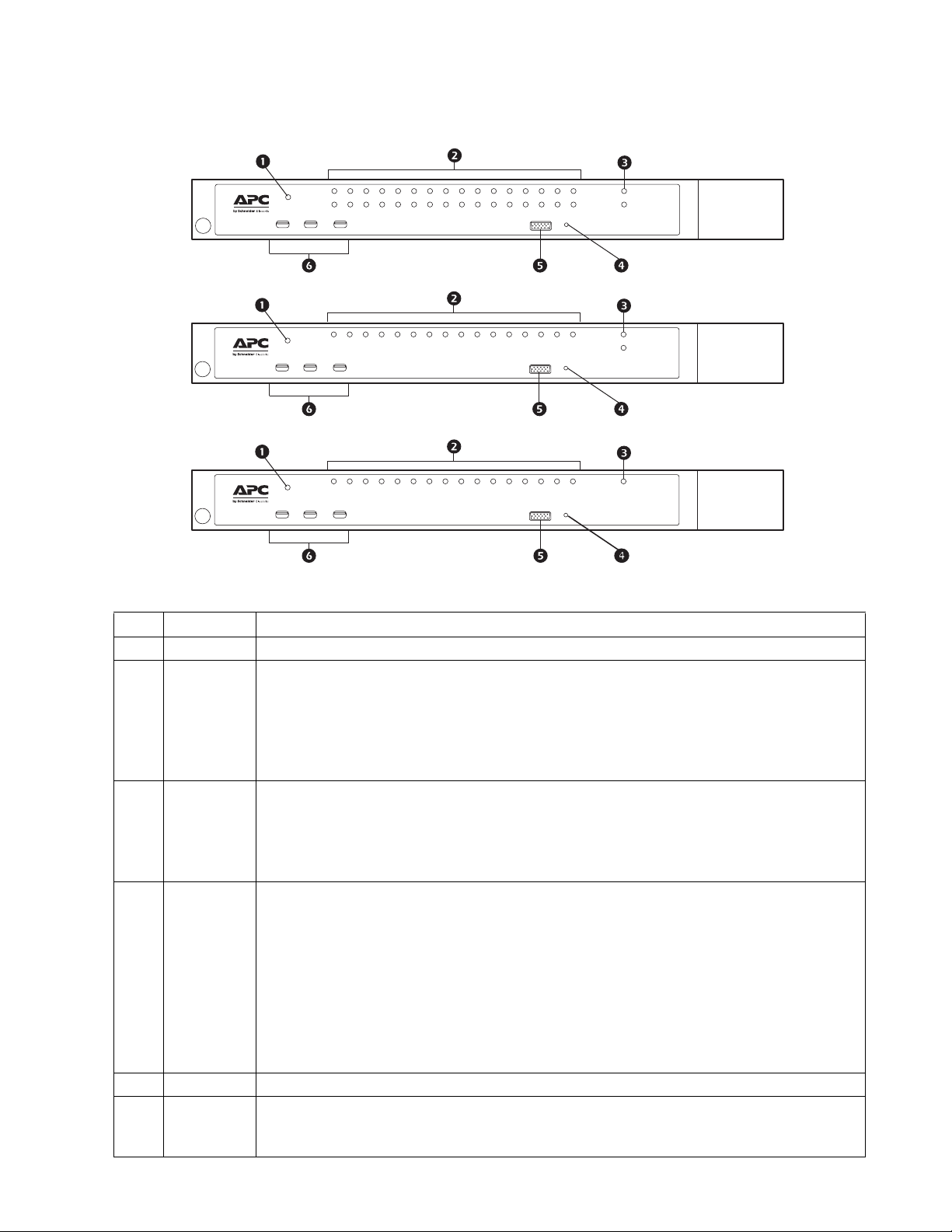
Front
Name
Item
Description
1 Power LED Illuminated when the unit is powered up and ready to operate.
2 Port LEDs Provides status information about corresponding KVM Ports.
• GREEN: The computer attached to the port is On Line.
• RED: The computer attached to the port is Selected (has KVM focus).
• GREEN + RED (ORANGE): The computer attached to the port is On Line and Selected.
The LEDs are continuously ON under normal conditions. An LED flashes at half second intervals
when its corresponding port is accessed under Auto Scan Mode or Skip Mode.
3 LAN LEDs Primary and Secondary 10/100/1000 Mbps LAN LEDs.
• RED: 10 Mbps
• RED + GREEN (ORANGE): 100 Mbps
4 Reset Switch Use a small object like a paper clip or ballpoint pen to press the reset switch.
• GREEN: 1000 Mbps
Flashes to indicate that the switch is being accessed.
• To perform a system reset, press and release when the unit is running.
• To reset to the factory default settings, press and hold for +3 seconds when the unit is running.
Note: This does not clear User Account information. See “Factory Default Settings” on
page 103, for information on clearing user account information.
• To return to factory default firmware settings, rather than any upgraded version press and hold
while powering on the unit. This allows recovery from a failed firmware upgrade so the upgrade
may be tried again.
Note: This operation is only performed after a firmware upgrade failure that results in the
device becoming inoperable.
5 Console Port A Rack LCD Console may be installed in this port.
6 USB Ports • Connect USB storage peripherals (CD/DVD, HD, flash drives, etc.).
• A USB keyboard and mouse can be used in place of, or in addition to, a keyboard and mouse
plugged in on the rear panel.
7KVM Switch KVM2132P, KVM2116P, KVM1116P User Manual
Page 20
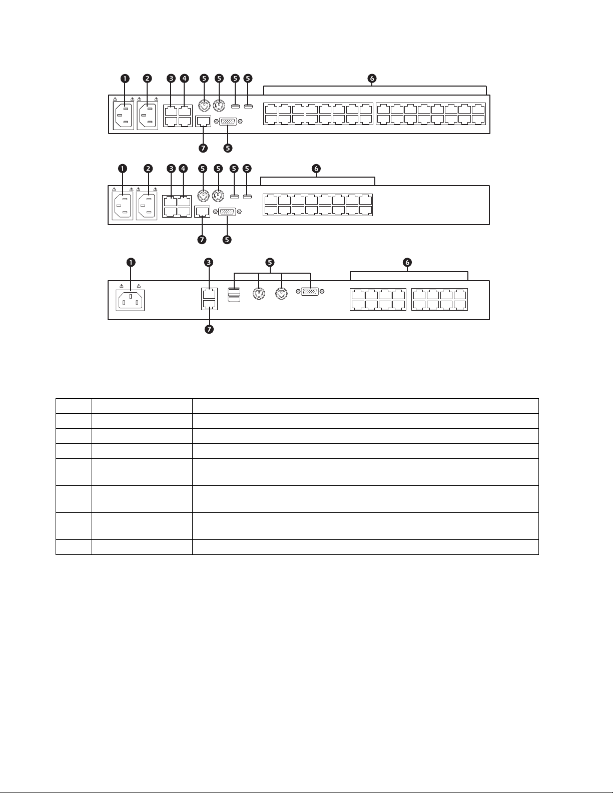
Rear
aem0370a
KVM2132P
KVM2116P
KVM1116P
Item Name Description
Power Socket 1 Plug power cable for Power Source 1 in here.
1
Power Socket 2 Plug power cable for Power Source 2 in here.
2
LAN Port(s) Connect the unit to the network interface (10/100/1000 Mbps) here
3
PDU Port(s) Connect to a PDU unit (which allows servers attached to the KVM switch to be booted
4
Local Console Port(s) Local console devices (keyboard, monitor and mouse), plug in here. Any combination
5
KVM Ports Cat 5e cables plug in to link the unit to the KVM Adapter Cables, which connect to the
6
Modem Port Dial in connection if the unit becomes unavailable over the network.
7
remotely over the net).
of USB and PS/2 keyboards and mice can be used.
servers.
KVM Switch KVM2132P, KVM2116P, KVM1116P User Manual 8
Page 21
Installation
Overview
KVM Adapter Cables connect the switch to the connected devices. A separate KVM Adapter Cable is
required for each server or device connection. See the list of KVM Adapter Cables on page 5 or contact
APC Customer Support for help.
Note: 1. Refer to the Safety section of this manual before installing the KVM switch.
2. Power to any device that will be connected to the installation must be turned off. Unplug
the power cords of any computers that have the Keyboard Power On function.
Rack Mounting
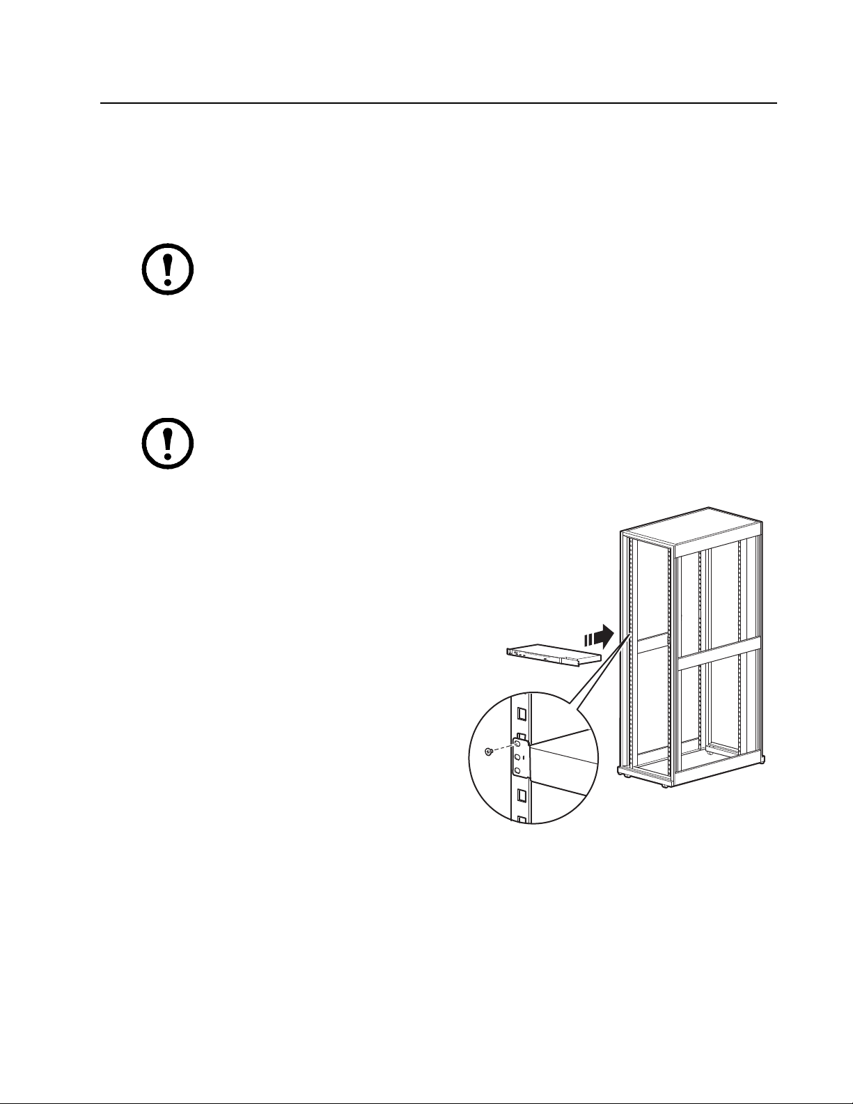
The switch can be mounted in a 19" (1U) rack. The mounting brackets can screw into either the front or
the back of the unit so that it can attach to the front or the back of the rack.
Note: Use cage nuts (not provided) for racks that are not pre-threaded.
Rack Mounting - Front
1. Position the switch in the front of the rack.
Align the mounting bracket holes with the
holes in the rack.
2. Secure the mounting brackets to the rack.
aem0372a
9KVM Switch KVM2132P, KVM2116P, KVM1116P User Manual
Page 22

Rack Mounting - Rear
1. Remove the brackets from the front of the
KVM switch.
Remove the plug from the alignment hole.
2. Install the smaller bracket from the front of
the unit to the back. Install the rack mounting
bracket from the inventory to the rear of the
unit.
3. Slide the switch into the rack. Align the
mounting bracket holes with the holes in the
rack.
aem0449a
4. Secure the mounting brackets to the rear of
the rack.
Optional KVM to LCD Console Mounting
The KVM switch can be mounted to a Rack LCD Console (not included). See the installation sheet for
the Rack LCD Console KVM switch bracket kit for more information.
aem0450a
KVM Switch KVM2132P, KVM2116P, KVM1116P User Manual 10
Page 23
Single Level Installation
aem0448a
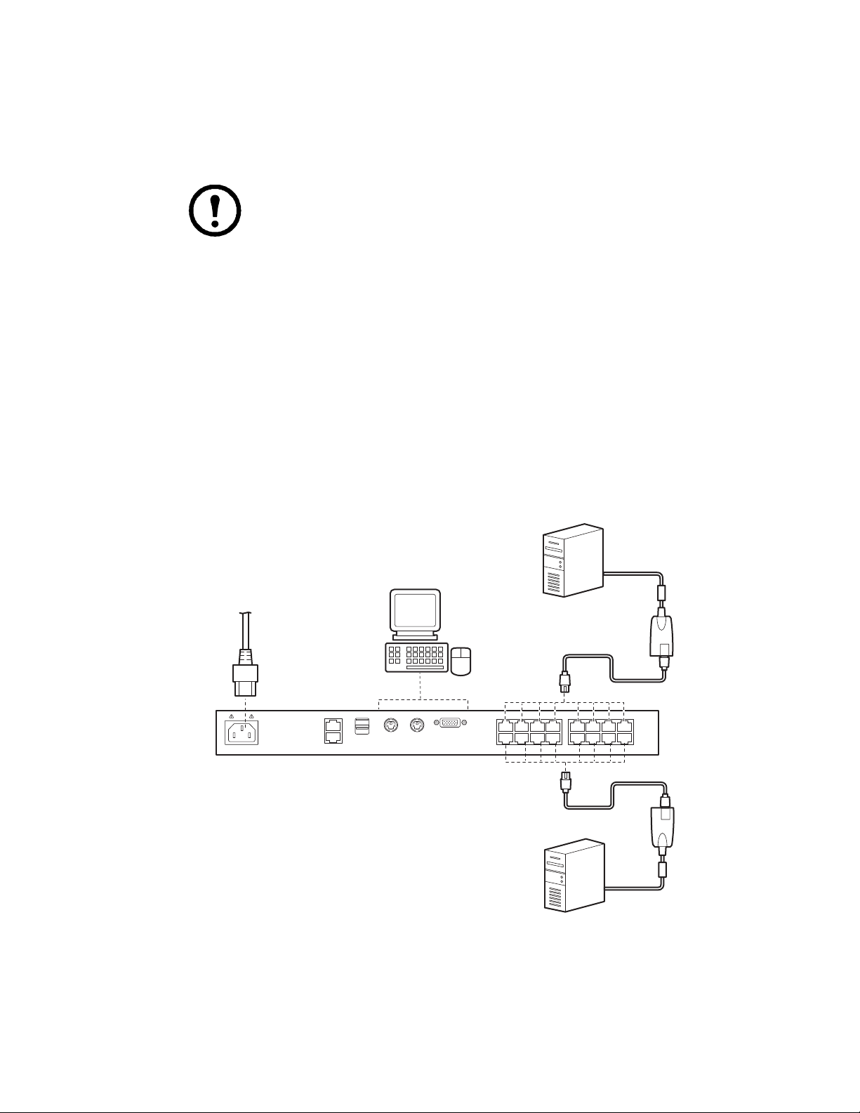
In a single level installation, no additional switches are tiered from the original switch.
1. Plug the keyboard, monitor, and mouse of your Local Console into the Console Ports of the KVM
parent switch. Each port is color coded and marked with an appropriate icon.
Note: 1. Any combination of keyboard and mouse connections can be used.
2. USB keyboards and mice can be plugged into the USB ports on the front panel or
into the console ports on the back.
2. Use Cat 5e cable to connect a KVM port to a KVM server module appropriate for the server
being installed.
3. Plug the connectors on the KVM server module into the appropriate server ports.
4. Plug a cable from the LAN or WAN into the KVM switch's primary network interface socket.
5. (Optional) Plug another cable from the LAN or WAN into the KVM switch's backup (secondary)
network interface socket.
6. (Optional) Use Cat 5e cable to connect the switch's Modem port to an SA0142 Serial Adapter.
Connect the Adapter's serial connector to the modem's DB-9 port.
7. Plug the supplied power cord(s) into the switch's power socket(s), then into an AC power source.
8. Turn on the servers.
KVM1116P Single Level Installation Diagram
11KVM Switch KVM2132P, KVM2116P, KVM1116P User Manual
Page 24
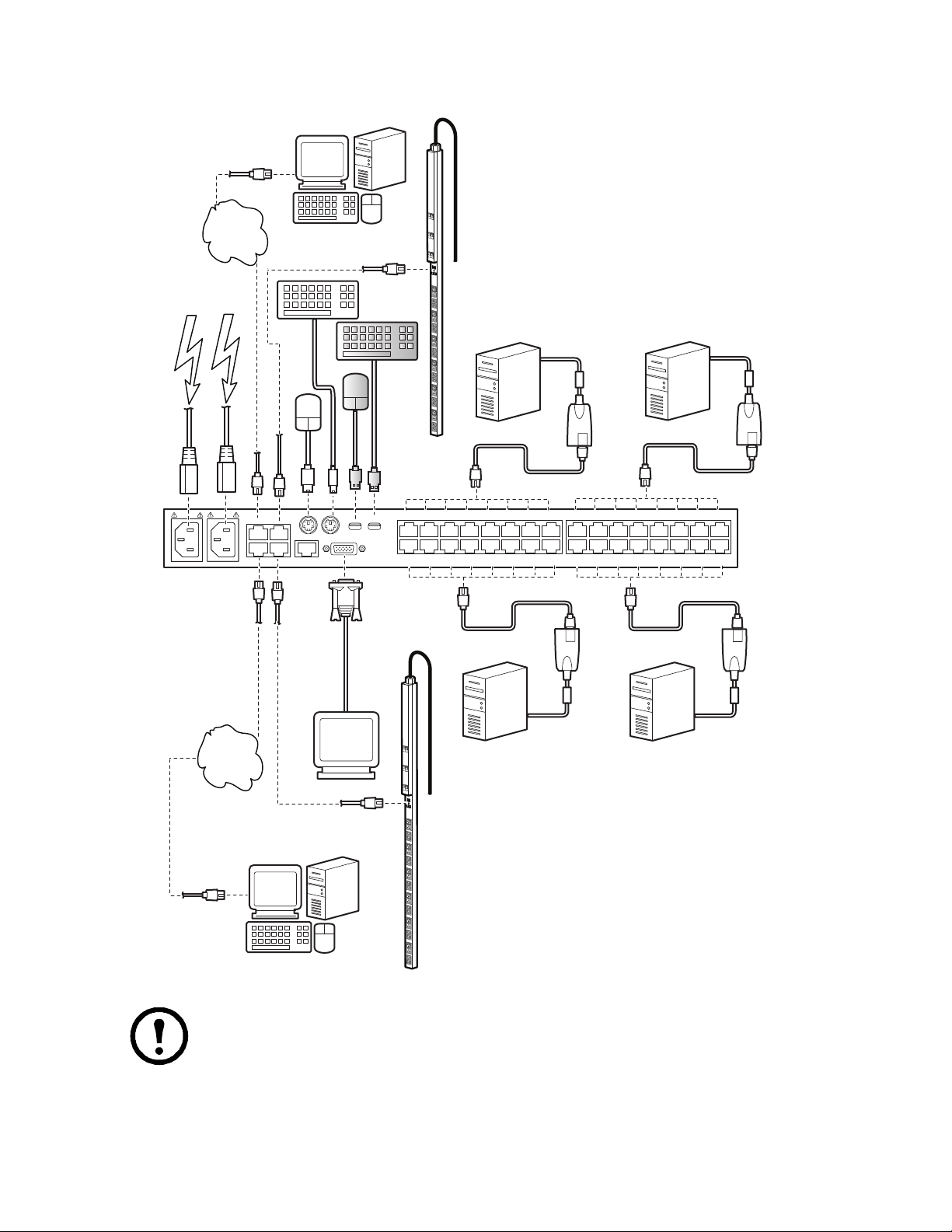
KVM2132P Single Level Installation Diagram
aem0379a
LAN 2
PDU 2
LAN 1 PDU 1
LAN/
Internet
LAN/
Internet
Remote
Console
Remote
Console
OR
KVM2132A
Note: KVM2116P Single Level Installation is the same except for the number of KVM
ports.
KVM Switch KVM2132P, KVM2116P, KVM1116P User Manual 12
Page 25
Tiering Multiple KVM Switches
aem0376a
KVM1116P
KVM0116A *
KVM-PS2
A tiered installation will greatly expand the number of servers that can be added to the installation.
Cascaded tiering adds capacity to a KVM installation, but the parent loses at least one KVM port for
each tiered KVM switch. KVM2132P, and KVM2116P support tiering up to 3 levels. When the KVM
consoles of the first-level KVM switch invoke the OSD, all computers on the tiered KVM installation
are listed in the port directory.
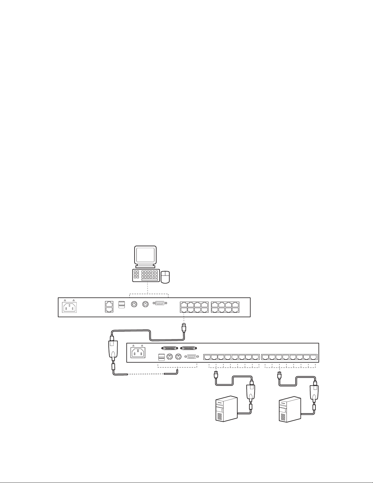
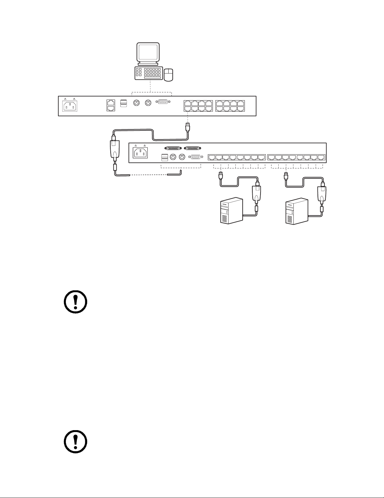
KVM1116P Two Level Installation
Up to 16 additional KVM switches can be tiered from the KVM ports of the original KVM switch. As
many as 256 servers can be controlled in a complete two level installation. In a tiered installation, the
(KVM1116P) switch is considered the First Level or Parent unit, the tiered switches are considered
Second Level or Child units (KVM0116A / KVM0108A) . Turn off power to all the devices, including
all pre-existing devices on the installation.
1. Use Cat 5e cable to connect any available KVM Port on the First Level unit (KVM1116P) to a
KVM-PS2 Adapter Cable.
2. Plug the adapter cable's KVM connectors to the Keyboard, Video, and Mouse Console ports of
the Second Level switch (KVM0116A / KVM0108A).
3. Connect any available KVM port on the Second Level unit to the Keyboard, Video, and Mouse
ports of the server.
4. Power on the First Level switch, then power on the Second Level switches .
5. Turn the servers on last.
Two Level Installation Diagram
* See the User Manual for KVM0116A and KVM0108A for more information about this unit.
13KVM Switch KVM2132P, KVM2116P, KVM1116P User Manual
Page 26
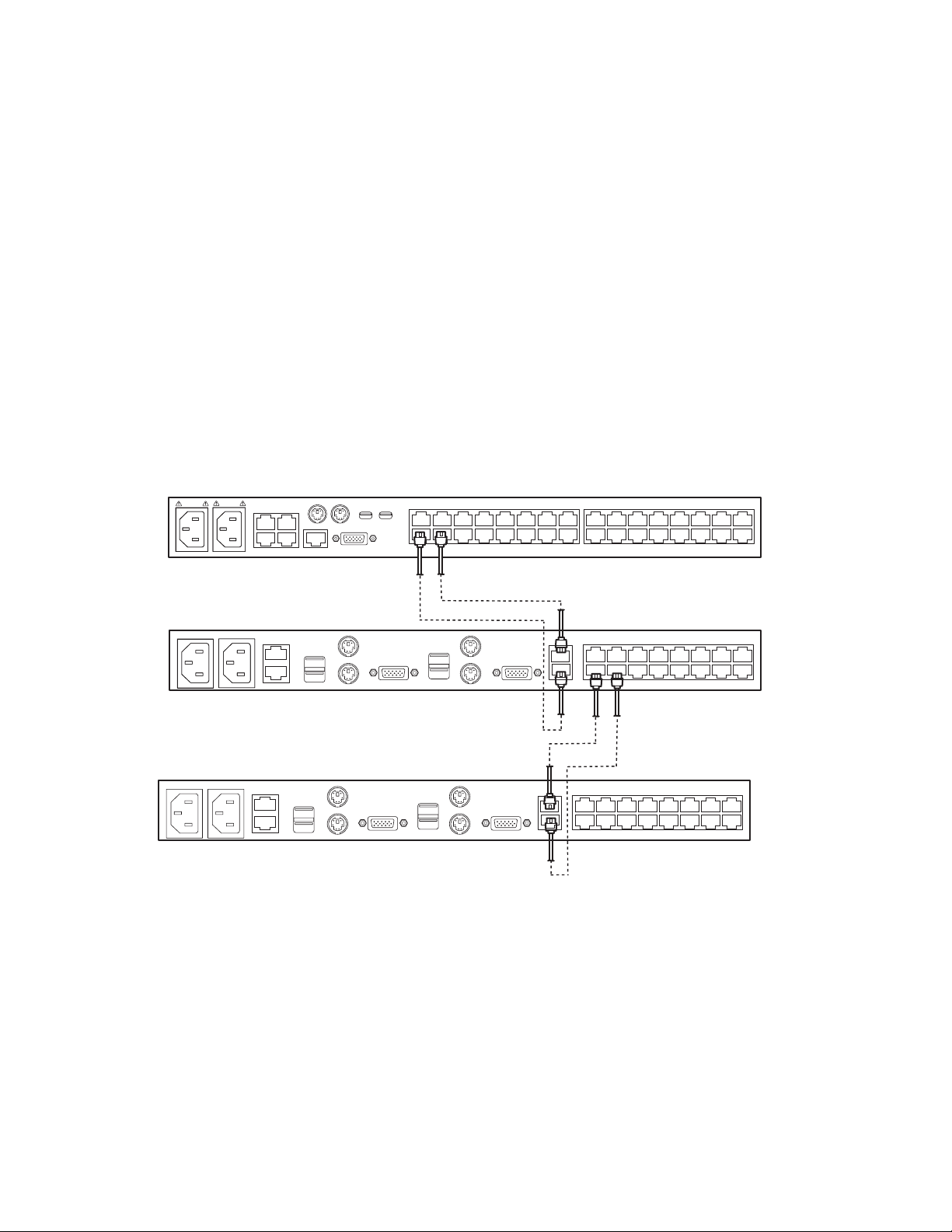
Three Level Installation and (1 or 2) Bus Configurations
KVM2132P (or KVM2116P)
KVM0216A *
aem0380a
KVM0216A *
In tiered installations, the number of bus connections between a parent and child KVM switch
determines the number of users that can simultaneously access the KVM ports of a child switch. A bus
connection is established by connecting a KVM port on the parent switch to a LAN port on the child
switch. The KVM switch (KVM2132P, KVM2116P) supports a maximum of two bus connections for
each tiered switch.
In a two-bus tiered configuration, two bus connections between every parent switch and child switch in
the installation are created so both KVM consoles on the first-level KVM switch can access the KVM
ports of any tiered switches at the same time. Console connectors of the child switches are inoperable.
In a one-bus tiered configuration only a single bus connection is created between a parent switch and a
child switch. Only one of the consoles connected to the parent switch has access to a child switch at any
time. The second console can still control and access the ports of the parent switch. Only one console of
each child switch is available to access the KVM ports on the same level or lower level switch. KVM
consoles connected to tiered switches cannot access the ports of a parent switch and can perform only
port switching and user profile changes. No other administrative functions can be executed.
KVM2132P / KVM2116P Two busTiered Diagram
* See the User Manual for KVM0216A for more information about this KVM switch.
KVM Switch KVM2132P, KVM2116P, KVM1116P User Manual 14
Page 27
KVM1116P One Bus Tiered Diagram
aem0376a
KVM1116P
KVM0116A *
KVM-PS2
* See the User Manual for KVM0116A and KVM0108A for more information about these KVM switches.
Hardware Setup
Cable Length Considerations
Note: KVM server modules are also referred to as KVM adapter cables.
• Do not exceed 66 feet (20m) between the switch and the local monitor.
• The distance between the First Level (Parent) KVM switch and the Second Level (Child) KVM
switch must not exceed 93 feet (30m).
• To support a resolution of 1280x1024, the recommended maximum distance between the KVM
switch and the KVM server module is 164 feet (50m).
• The total distance between any KVM switch and any KVM server module in the installation
cannot exceed 164 feet (50m).
Hot Plugging
The KVM switch supports hot plugging. Components can be removed and added by unplugging and replugging cables from the ports without shutting the unit down.
Note: The Operating System of the server must support hot plugging for this function to
work properly.
15KVM Switch KVM2132P, KVM2116P, KVM1116P User Manual
Page 28

The Adapter ID Function
Server module information (the Adapter ID, port name, OS, keyboard language, and access mode) is
stored on the server module. The switch's Adapter ID function stores this information along with the
server module's configuration information (access rights, etc.), so that when a server is moved with its
server module from one port to another, its settings do not have to be reconfigured. The Adapter ID
function restores them at the new location. Only the port number changes.
When moving the server and server module cable to another switch, only the information that is stored
on the server module is retained. Other settings must be reconfigured, or the Backup/Restore function
can be used (see page 93).
Port settings are stored with the server module. If a server is moved to a new port without its original
server module, or if a different server is connected to the server module, the port settings for the new
server must be manually configured. See “Sidebar Utilities” on page 38 for port configuration details.
Powering Off and Restarting
If the switch is powered off, or if the switch loses power and needs to be restarted, wait 10 seconds
before powering it back on. Servers should not be affected, but if any fail, restart them.
Port ID Numbering
Each server on the installation is assigned a unique Port ID.
1. A server attached to a first level KVM switch has a one segment Port ID that corresponds to the
KVM Port number to which it is connected.
2. A server attached to a Second Level KVM switch has a two segment Port ID.
a. The first segment represents the First Level unit’s KVM Port number that connects to the
Second Level KVM unit.
b. The second segment represents the Second Level unit’s KVM Port number that connects to
the server.
Example: A Port ID of 12 - 3 refers to a server connected to KVM Port 3 of a Second Level unit (child)
connected to KVM Port 12 of the First Level unit (parent).
A server attached to a third level KVM switch has a three segment Port ID. Example: 12-03-05.
Port Selection
Port selection is accomplished by means of the GUI. See Port selection details on page 37.
PDU Connection (KVM2132P, KVM2116P)
• Connect the PDU and KVM switch with connection cable AP5641.
• The RJ12 connector plugs into the PDU port labeled “Serial”.
• The RJ45 connector plugs into the KVM port labeled “PDU1” or “PDU2”.
KVM Switch KVM2132P, KVM2116P, KVM1116P User Manual 16
Page 29
Super Administrator Setup
Overview
First Time Setup
The Super Administrator sets up the unit for user operation (set the network parameters, change the
default Super Administrator login) for the first time from the local console if possible. See “IP Address
Determination” on page 105 to set up remotely.
Since this is the first time you are logging in, use the default Username “apc” and Password “apc”. The
Local Console Main Page will open following a successful login.
Note: For security purposes, changing to a unique Username and Password is recommended.
Network Setup
1. Click the Device Management tab.
2. Select the Network tab.
3. Fill in the fields according to the information provided under Network, page 68.
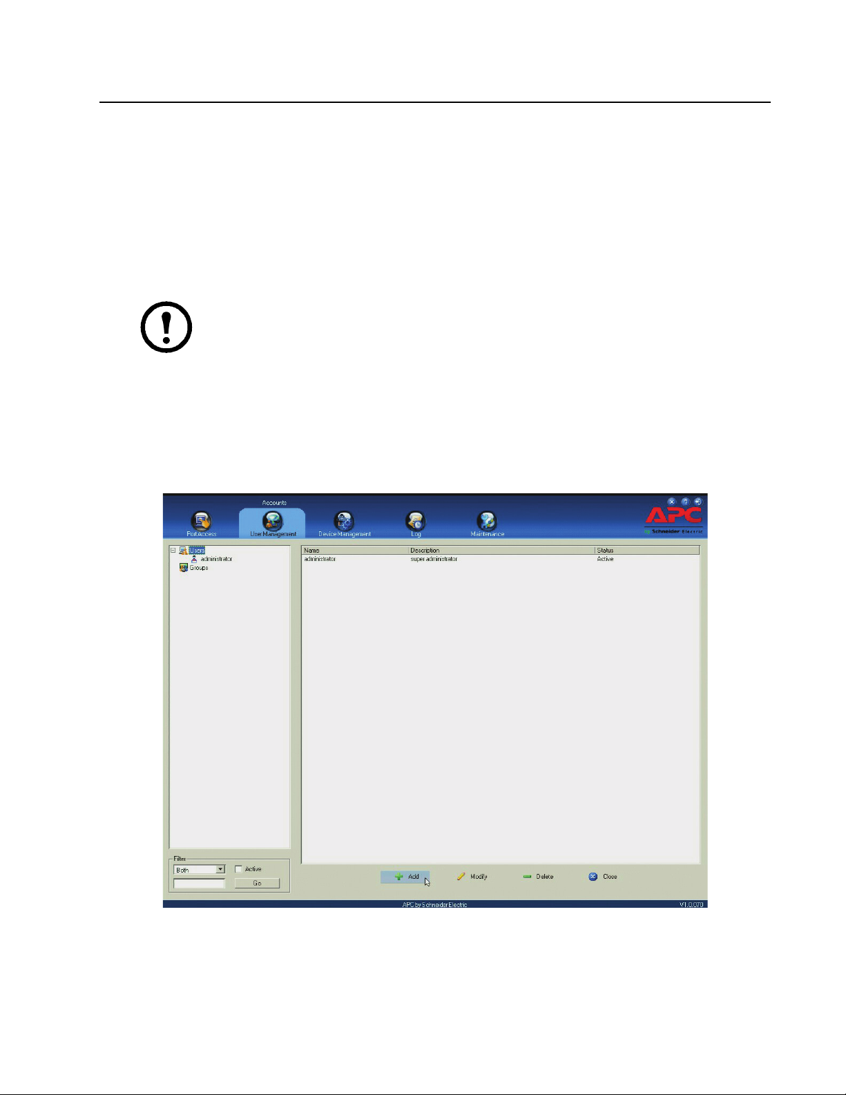
Changing the Super Administrator Login
1. At the top of the screen, click the User tab.
The page lists Users and Groups in the Sidebar at the left, and more details in the center panel.
The first time the page is accessed, only the Super Administrator appears.
17KVM Switch KVM2132P, KVM2116P, KVM1116P User Manual
Page 30
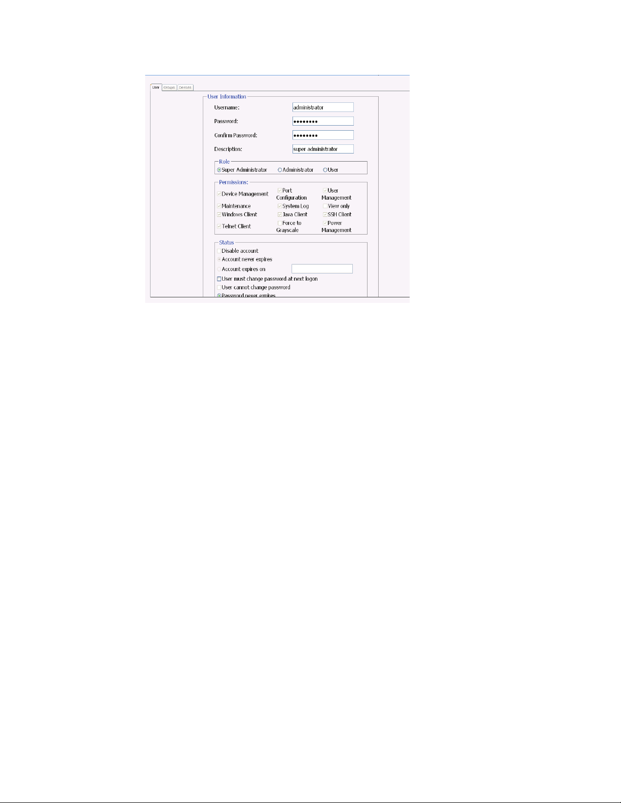
2. Click on Administrator in the left panel or select Administrator in the central panel.
Click Modify at the bottom of the page to open the User Information page.
3. Change the Username and Password.
4. Enter the new password again in the Confirm Password field and click Save.
5. Click OK in the dialog box that says the change completed successfully.
6. Click on another item on the Local Console Main Page, to close the User Information page.
KVM Switch KVM2132P, KVM2116P, KVM1116P User Manual 18
Page 31

Logging In
Overview
Switches can be accessed from a local console, an internet browser, a Windows application (AP)
program, and a Java application (AP) program.
The switch's authentication procedure requires a valid username and password. Invalid login information
will open an Invalid Username or Password, or Login Failed message.
Note: If the login fails, log in again with a correct username and password. If the number of
invalid login attempts exceeds a specified amount, a timeout period is invoked. The timeout
period must expire before another login is attempted. See Login Failures, page 75.
Local Console Login
Enter your Username and Password, then click Login to open the Local Console Main Page. The Local
Console Main Page is similar to the Web Browser, WinClient and Java Client Main Pages. For a
description of the Web Browser Main Page, see page 22.
Browser Login
The switch can be accessed from an Internet browser running on any platform.
1. Specify the IP address of the switch you want to access in the browser's address bar.
Note: If the administrator added a login string for security purposes, include a
forward slash and the login string along with the IP address when you log in.
2. When a Security Alert dialog box opens, accept the certificate. It can be trusted. If a second
certificate appears, accept it as well to open the login page.
3. Provide your username and password and click Login to open the Web Main Page.
19KVM Switch KVM2132P, KVM2116P, KVM1116P User Manual
Page 32

Windows Client AP Login
The Windows AP Client allows direct remote access to Windows systems users, without going through a
browser although initially the Windows AP Client program must be downloaded from the browser page.
Double-click the WinClient.exe icon to open the Windows Client Connection Screen:
The Windows Client AP Connection Screen
Item Description
Menu Bar The Menu Bar contains two items: File and Help.
• The File Menu allows the operator to Create, Save, and Open user created Work files.
• The Help Menu displays the WinClient AP version.
Server List WinClient.exe searches the user's local LAN segment for switches, and lists them in this
box. Double-click to connect to one of these units.
Note: 1. The switch’s Enable Device List configuration parameter must be enabled.
2. Units in the Server List are those whose Access Port settings match the number
specified for Port in the Server area of this dialog box.
Server Used when connecting to a switch at a remote location. Select an address from the IP list
box. If the address isn't listed, enter the target IP address in the IP field, and its port
number in the Port field. If you don't know the port number, contact your Administrator.
• When the IP address and Port number have been specified, click Connect.
• When finished, return to this dialog box and click Disconnect to end the connection.
Message Panel Lists status messages regarding the connection to the switch.
Switch to Remote View Click to switch to the GUI Main Page (page 23).
Connect using Windows Client AP
1. Select the device from the Server List box and double-click on it or specify its IP address and port
number in the Server IP and Port input boxes.
2. Click Connect to open the Login dialog box.
3. Enter a valid Username and Password, and click OK.
4. Following authentication, the Switch to Remote View button becomes active. Click it to connect
to the switch and bring up its GUI Main Page.
The File Menu
Create, Save, and Open user created Work files. A Work File consists of all the information specified in
a Client session including the Server List, Server IP list items, and Hotkey settings. The Client program
opens with the values contained in the current work file. The current work file consists of the values that
were in effect the last time the program was closed.
New Create a named work file so its values will not be lost, and it will be available for future recall.
Open Open a previously saved work file and use the values contained in it.
Save Save the values presently in effect as the current work file.
Exit Exits the WinClient.
KVM Switch KVM2132P, KVM2116P, KVM1116P User Manual 20
Page 33

Java Client AP Login
The Java AP Client provides direct remote access to non-Windows systems users although the Java AP
Client program is initially downloaded from the browser page. Double-click the JavaClient.jar icon to
open the Java Client Connection Screen.
Item Description
Server List JavaClient.jar searches the user's local LAN segment for KVM switches, and lists them
in this box. Double-click to connect to one of these units.
Note: 1. The switch’s Enable Device List configuration parameter must be enabled.
2. Units in the Server List are those whose Access Port settings match the number
specified for Port in the Server area of this dialog box.
Server Used when connecting to a switch at a remote location. Select an address from the IP list
box. If the address isn't listed, enter the target IP address in the IP field, and its port
number in the Port field. If you don't know the port number, contact your Administrator.
• When the IP address and Port number have been specified, click Connect.
• When finished, return to this dialog box and click Disconnect to end the connection.
Message Panel Lists status messages regarding the connection to the switch.
Switch to Remote View Click this button to switch to the GUI Main Page.
Connect using - Java Client AP
To connect to a KVM switch:
1. Select the device from the Server List box and double-click on it or specify its IP address and port
number in the Server IP and Port input boxes.
2. Click Connect to open the Login dialog box.
3. Enter a valid Username and Password, and click OK.
4. Following authentication, the Switch to Remote View button becomes active. Click it to connect
to the switch and open its GUI Main Page.
21KVM Switch KVM2132P, KVM2116P, KVM1116P User Manual
Page 34

The User Interface
Overview
The look of the user interface Main Page varies depending on the method used to log in.
The Web Browser Main Page
Access the KVM switches with most standard web browsers. Once users log in and are authenticated, the
Web Browser Main Page opens with the Port Access page displayed.
Note: Depending on a user's type and permissions, not all elements appear.
Item Description
Tab Bar Contains the KVM switch's main operation categories. Items appearing in the tab bar are
determined by user type, and authorization options.
Menu Bar Contains operational sub-categories related to the selected item in the tab bar. Items in the
menu bar are determined by user type, and authorization options.
Sidebar Provides a tree view listing of ports related to the tab bar and menu bar selections. Click an
item in the Sidebar to open a detail page. Expand or narrow the scope of the ports that
appear in the tree by clicking the Filter button at the bottom of the Sidebar. See the Filter
function on page 40 for details.
About Provides information regarding the switch's current firmware version.
Logout Click this button to log out of your KVM switch session.
Welcome Message If enabled (see Welcome Message*, page 112), a welcome message displays here.
KVM Switch KVM2132P, KVM2116P, KVM1116P User Manual 22
Page 35

Interactive Display Panel The main work area. The screens reflect menu choices and Sidebar item selection.
The Tab Bar
The number and type of icons that appear on the Tab Bar at the top of the page are determined by user
type (Super Administrator, Administrator, User) and permissions.
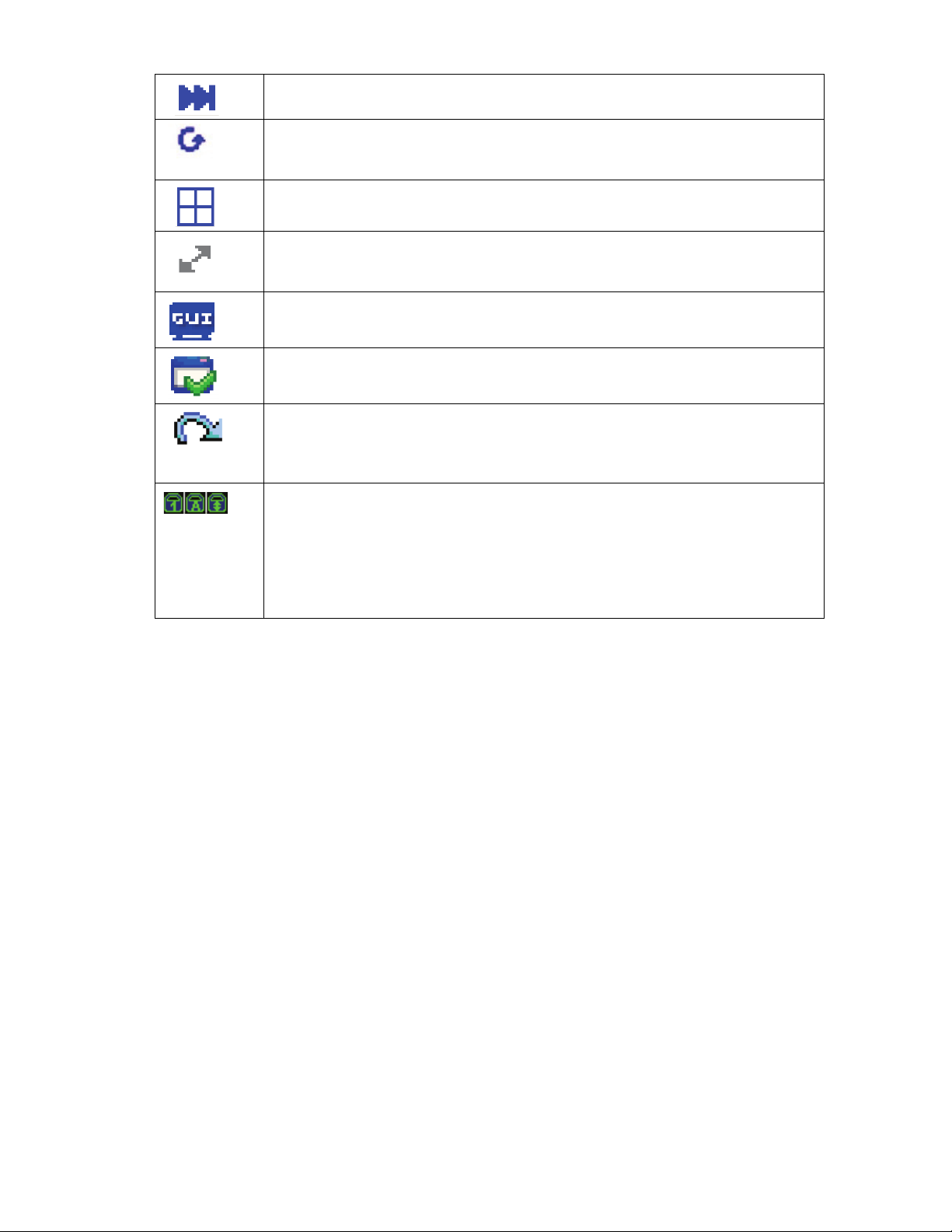
Icon Description
Port Access: The Port Access page is used to access and control the devices on the KVM switch
installation. This page is available to all users.
Create and manage Users and Groups, also assign devices to them. This tab is available to the Super
Administrator, administrators, and users who have User Management permission. The tab does not
appear for other administrators and users.
Configure and control the overall operation of the KVM switch. This page is available to the Super
Administrator, administrators, and users who have Device Management permission. The tab doesn't
appear for other administrators and users.
Displays the contents of the log file.
Install new firmware; backup and restore configuration and account information; ping network
devices; and restore default values. This page is available to the Super Administrator (and
Administrators and Users with Maintenance permission). The icon doesn't display on the page of
ordinary administrators and users.
Download AP versions of the Windows Client, the Java Client, and the Log Server. This page is
available to all users. The programs that can be downloaded depend on the user's permissions.
There are two small icons at the extreme right of the page.
Icon Description
Click the About icon to see information about the KVM switch firmware version.
Click the Logout icon to log out and end your KVM switch session.
The AP GUI Main Page
The GUI Main Page is similar to that of the Web Browser. The differences are:
1. The AP GUI version does not have a menu bar below the tab bar. It has tabs like a notebook. Like
the Web Browser interface, the makeup of the tabs changes depending on the items selected on
the main Tab Bar and in the Sidebar.
2. In addition to Filter, there are also buttons for Scan and Array Mode at the bottom of the Sidebar.
See “Port Access” on page 37 for more information.
3. There is a hidden Control Panel at the upper (default position) or lower center of the screen that
becomes visible when the mouse is moved over it.
4. There is an additional icon at the extreme right of the page. Click this icon to close the GUI Main
Page and go to the display of the last selected port.
23KVM Switch KVM2132P, KVM2116P, KVM1116P User Manual
Page 36

5. The GUI can be navigated via the keyboard.
Keys Action
Ctrl + P Opens the Port Access page.
Ctrl + U Opens the User Management page.
Ctrl + C Opens the Device Management page.
Ctrl + L Opens the Log page.
Ctrl + M Opens the Maintenance page.
Ctrl + D Opens the Download page.
F1 To see About information
F2 To edit the port name of the selected port
F4 Selects the Sidebar (left) panel.
F5 Selects the main (right) panel
F7 Closes the GUI.
F8 To log out.
The Local Console GUI Main Page
The main difference between the Local Console GUI Main Page and the Java and Windows AP GUI
Main Page is the Local Console Main Page does not have a tab for Download.
The Control Panel
The WinClient Control Panel (for the ActiveX Web Viewer and WinClient AP) contains the most
complete functionality. This section describes the WinClient Control Panel.
The Java Control Panel (for the Web Viewer and Java Client AP) does not enable all of the features that
the WinClient Control Panel enables. The features that are common to both panels also function
similarly.
The Control Panel is hidden at the upper (the default position) or lower center of the screen, and becomes
visible when the mouse moves over it. The panel consists of three rows: an icon row at the top, and two
text rows below.
Note: The icons that appear can be user selected. See “Control Panel Configuration” on
page 35, for details.
• By default, the upper text row shows the video resolution of the remote display. As the mouse
pointer moves over the icons, the information in the upper text row changes to describe the icon's
function. If a message from another user is entered in the message board, and the message board
has not been opened, the message will appear in the upper row.
KVM Switch KVM2132P, KVM2116P, KVM1116P User Manual 24
Page 37

• The lower row shows the IP address of the device you are accessing at the left of the row. The
center of the row indicates which bus the user is on (the number before the slash), and the total
number of users on that bus (the number behind the slash).
Note: Bus and user information only display if enabled.
• Right click in the text row area to open a menu-style version of the toolbar. Select options for the
Screen Mode, Zoom, Mouse Pointer type, and Mouse Sync Mode.
• To move the Control Panel to a different location on the screen, move the mouse pointer over the
text row area, then click and drag.
25KVM Switch KVM2132P, KVM2116P, KVM1116P User Manual
Page 38

WinClient Control Panel Functions
Icon Function
Toggle icon. Click to make the Control Panel always display on top of other screen
elements. Click again to have it display normally.
Macro icon.Click to open the Macros dialog box (see page 30 for details).
Hammer icon. Click to open the Video Options dialog box. Right-click to perform a quick
Auto Sync (see “Video Settings” on page 30 for details).
Click to perform a video and mouse autosync operation. It is the same as clicking the
Auto-sync button in the Video Options dialog box (see “Video Settings” on page 30).
Toggle the display between Full Screen Mode and Window Mode.
Click to take a snapshot (screen capture) of the remote display. See “Snapshot” on
page 35 for details.
Click to open the Message Board (see “The Message Board” on page 31).
Click to send a Ctrl+Alt+Del signal to the remote system.
Click to toggle the remote display between color and gray scale views.
Click to open the Virtual Media dialog box. See “Virtual Media” on page 32 for details.
Note: 1. This icon is displayed on the switches only.
2. This icon displays in gray when the function is disabled or not available.
Click to zoom the remote display window.
Note: This feature is only available in windowed mode (Full Screen Mode is off). See
“Zoom” on page 33 for details.
Click to open the on-screen keyboard (see “The On-Screen Keyboard” on page 33).
Click to select the mouse pointer type.
Note: This icon changes depending on which mouse pointer type is selected (see “Mouse
Pointer Type” on page 34)
Click to toggle Automatic or Manual mouse sync.
• When the selection is Automatic, a green V appears on the icon.
• When the selection is Manual, a red X appears on the icon.
See “Mouse DynaSync Mode” on page 34 for details.
Click to open a list of User macros in order to access and run macros more conveniently
than using the Macros dialog box.
Under an accessed port, click to skip to the first port accessible to the user on the entire
installation without going to the Port Access page.
Under an accessed port, click to skip to the first port accessible to the user that is previous
to the current one without going to the Port Access page.
Under an accessed port, click to skip to the first port accessible to the user that is after the
current one without going to the Port Access page.
KVM Switch KVM2132P, KVM2116P, KVM1116P User Manual 26
Page 39
Under an accessed port, click to skip to the last port accessible to the user on the entire
installation without going to the Port Access page.
Under an accessed port, click to begin Auto Scan Mode. The KVM switch automatically
switches among the ports selected for Auto Scanning with the Filter function (see Filter,
page 40). Monitor the activity of the ports without switching through them manually.
Under an accessed port, click to invoke Panel Array Mode (see “Panel Array Mode” on
page 88).
Under an accessed port, click this icon to select the Adapter cable (Short, Medium, Long)
that connects the device to the switch. The length of the line in the icon indicates the
selection.
Under an accessed port, click to recall the GUI.
Click to open the Control Panel Configuration dialog box. See “Control Panel
Configuration” on page 35, for more information.
Click to exit the viewer.
• Exit from a Browser Viewer session brings you back to the web browser Main Page.
• Exit from a WinClient AP session brings you back to the login dialog box.
• Exit from a Java Client AP session brings you back to the login dialog box.
These icons show the Num Lock, Caps Lock, and Scroll Lock status of the remote
computer.
• When the lock is On, the LED is bright green and the lock hasp is closed.
• When the lock is Off, the LED is dull green and the lock hasp is open.
Click on the icon to toggle the status.
Note: These icons and your local keyboard icons are in sync. Press a Lock key on your
keyboard and the icon changes accordingly.
Macros
There are three functions in the Macros dialog box: Hotkeys, User Macros, and System Macros.
Hotkeys. The Hotkey Setup utility (accessed by clicking the icon), lets you configure which hotkeys
perform actions. The hotkeys that invoke an action are shown to the right of its name. Click to put a
check in the checkbox to the left of an action's name to enable or disable its hotkey.
To change the hotkey for an action:
1. Highlight the Action, then click Set Hotkey.
2. Press your selected Function keys (one at a time). The key names appear in the Hotkeys field as
you press them.
a. The same function keys can be used for more than one action, as long as the key sequence
is not the same.
b. To cancel setting a hotkey value, click Cancel. To clear an action's Hotkeys field, click
Clear.
3. When you have finished entering your sequence, click Save. To reset all the hotkeys to their
default values, click Reset.
27KVM Switch KVM2132P, KVM2116P, KVM1116P User Manual
Page 40

Hotkey actions:
Action Explanation
Exit remote location Breaks the connection to the KVM switch and returns you to local client computer
operation. This is equivalent to clicking the Exit icon on the Control Panel. The default
keys are F2, F3, F4.
Adjust Video Opens the Video Settings dialog box. This is equivalent to clicking the Video Settings icon
on the Control Panel. The default keys are F5, F6, F7.
Toggle Control Panel Toggles the Control Panel Off and On. The default keys are F3, F4, F5.
Toggle mouse display If the display of the two mouse pointers (local and remote) is confusing or annoying, shrink
the non-functioning pointer down to a tiny circle, which can be ignored. This function is a
toggle. Use the hotkeys to bring the mouse display back to its original configuration. This is
equivalent to selecting the Single pointer type from the Mouse Pointer icon on the Control
Panel. The default keys are F7, F8, F9.
Note: The Java Control Panel does not have this feature.
Adjust mouse This synchronizes the local and remote mouse movements. The default keys are F7, F8, F9.
Video Auto-sync This combination performs an auto-sync operation. It is equivalent to clicking the Video
Autosync icon on the Control Panel. The default keys are F8, F7, F6.
Show/Hide Local
Cursor
Substitute Ctrl key If your local computer captures Ctrl key combinations, preventing them from being sent to
Substitute Alt key In order to implement [Alt + Tab] and [Ctrl + Alt + Del] effects on the remote server,
Toggles your local mouse pointer off and on. This is equivalent to selecting the Null pointer
type from the Mouse Pointer icon on the Control Panel. The default keys are F4, F5.
the remote server, implement their effects on the remote server by specifying a function key
to substitute for the Ctrl key. Example: Substituting the F11 key, pressing [F11 + 5] would
appear to the remote server as [Ctrl + 5]. The default key is F11.
another key is substituted for the Alt key. Substituting the F12 key, for example, you would
use [F12 + Tab] and [Ctrl + F12 + Del]. The default key is F12.
User Macros. User Macros perform specific actions on the remote server.
To create the macro:
1. Select User Macros, then click Add.
2. Replace the “New Macro” text in the dialog box with a name of your choice for the macro.
3. Click Record. The dialog box closes, and a small panel opens at the top left of the screen.
4. Press the keys for the macro.
a. To pause macro recording, click Pause. To resume, click Pause again.
b. Clicking Show opens a dialog box that lists each keystroke that you make, together with the
amount of time each one takes:
c. Click Cancel to cancel all keystrokes.
d. When you have finished, click Stop. (This is the equivalent of clicking Done in Step 5.)
Note: 1. The function is not case-sensitive.
2. When recording the macro, the focus must be on the remote screen not the macro
dialog box.
3. Only the default keyboard characters may be used.
5. If the Show dialog box has not been opened, click Done when you have finished recording your
macro. The screen returns to the Macros dialog box with system macro key presses displayed in
the Macro column
6. To change keystrokes, select the macro and click Edit. This dialog box is similar to the one for
Show. Keystrokes, order, etc. can be changed.
KVM Switch KVM2132P, KVM2116P, KVM1116P User Manual 28
Page 41

Three ways to run macros:
1. Use the assigned hotkey.
2. Click on the macro from the Macro List on the Control Panel.
3. Open the Macros dialog box and click Play.
Run the macro from the Macros dialog box to have the option of specifying how the macro runs.
– Click Play Without Wait to run the keypresses one after another with no time delay between
them.
– Click Play With Time Control and wait for the amount of time between key presses that you
took when you created the macro. Click on the arrow next to Play to choose.
– Click Play without opening the list to run with the default choice (NoWait or TimeCtrl), which
is shown in the Playback column. Change the default choice by clicking on the current choice
and selecting the alternate choice.
Note: User Macros are stored on the Local Client computer of each user.
There is no limit on the of number of macros, the size of the macro names, or makeup of the
hotkey combinations.
Click the Search button at the bottom of the dialog box to filter the list of macros in the upper panel to
play or edit. Click a radio button to choose whether to search by name or by key. Enter a string for the
search, then click Search. All instances that match the search string appear in the upper panel.
System Macros. System Macros are used to create exit macros for closing a session.
Example: As an added measure of security, create a macro that sends the Winkey-L combination which
will cause the remote server's log in page to open the next time the device is accessed. To create the
macro:
1. Select System Macros, then click Add.
2. In the dialog box, replace the “New Macro” text with a name for the macro.
3. Click Record to close the dialog box, and open a small panel at the top left of the screen:
4. Press the keys for the macro.
a. To pause macro recording, click Pause. To resume, click Pause again.
b. Click Show to open a dialog box listing each keystroke that you make, together with the
amount of time each one takes.
5. If Show has not been opened, click Done when you have finished recording your macro. Return
to the Macros dialog box and the system macro key presses display in the Macro column
6. To change keystrokes, select the macro and click Edit. A dialog box similar to the one for Show
opens. Keystrokes, order, etc. can be changed.
Once system macros have been created, they are available for use on a port-by-port basis. Select them on
a port's Port Configuration > Port Properties page.
29KVM Switch KVM2132P, KVM2116P, KVM1116P User Manual
Page 42

Video Settings
Clicking the Hammer icon on the Control Panel brings up the Video Settings dialog box. Adjust the
placement and picture quality of the remote screen on your monitor with these options.
Options Usage
Screen Position Adjust the horizontal and vertical position of the remote server window by clicking the
Arrow buttons.
Auto-Sync Click to have the vertical and horizontal offset values of the remote screen detected and
automatically synchronized with the local screen.
Note: 1. If the local and remote mouse pointers are out of sync, in most cases, performing
this function will bring them back into sync.
2. This function works best with a bright screen.
3. If the results are unsatisfactory, use the Screen Position arrows to position the remote
display manually.
RGB Drag the slider bars to adjust the RGB (Red, Green, Blue) values. When an RGB value is
increased, the RGB component of the image is correspondingly increased. If you enable
Set to Grayscale, the remote video display is changed to grayscale.
Gamma This section allows you to adjust the video display's gamma level.
Network Type Select the type of internet connection that the local client computer uses. The switch will
use that selection to automatically adjust the Video Quality and Detect Tolerance settings
to optimize the quality of the video display.
Since network conditions vary, if none of the pre-set choices work well, select Customize
and use the Video Quality and Detect Tolerance slider bars to adjust the settings to suit
your conditions.
Video Quality Drag the slider bar to adjust the overall Video Quality. The larger the value, the clearer the
picture and the more video data goes through the network. Depending on the network
bandwidth, a high value may adversely effect the PDU response time.
Enable Refresh Select Enable Refresh and enter a number from 1 through 99. The KVM switch will
refresh the screen at the interval specified. This feature is disabled by default. Click to put
a check mark in the box next to Enable Refresh to use this feature.
Note: 1. The switch starts counting the time interval when mouse movement stops.
2. Enabling this feature increases the volume of video data transmitted over the network.
The lower the number specified, the more often the video data is transmitted. Setting the
value too low may adversely affect PDU response.
Transparency Adjusts toolbar transparency when the GUI hotkey is invoked. Slide the bar until the
display in the example window is satisfactory.
Color Depth Control This setting determines the richness of the video display by adjusting the amount of color
information.
Detect Tolerance This setting governs detecting or ignoring pixel changes. A high setting can result in a
lower quality display due to less data transfer. A lower setting will result in better video
quality. Setting the threshold too low may allow too much data to be transferred, negatively
impacting network performance.
KVM Switch KVM2132P, KVM2116P, KVM1116P User Manual 30
Page 43

Gamma Adjustment. If it is necessary to correct the gamma level for the remote video display, use the
Gamma function of the Video Adjustment dialog box.
• Under Basic configuration, there are ten preset and four user-defined levels to choose from.
Choose the most suitable one from the list.
• For greater control, click the Advanced button to open the dialog box
• Click and drag the diagonal line at as many points as needed for the display output desired.
• Click Save As to save up to four user-defined configurations. Saved configurations can be opened
from the list box.
• Click Reset to abandon any changes and return the gamma line to its original position.
• Click OK to save your changes and close the dialog box.
• Click Cancel to abandon your changes and close the dialog box.
Note: For best results, change the gamma while viewing a remote server.
The Message Board
A message board has been provided for users to communicate and to alleviate access conflicts.
The buttons on the Button Bar are toggles. Their actions are described in the table below:
Button Action
Enable/Disable Chat. When disabled, messages posted to the board are not displayed. The button is
shadowed when Chat is disabled. The icon displays next to the user's name in the User List panel
when the user has disabled Chat.
Occupy/Release Keyboard/Video/Mouse. When you Occupy the KVM, other users cannot see the
video, and cannot input keyboard or mouse data. The button is shadowed when the KVM is occupied.
The icon displays next to the user's name in the User List panel when the user has occupied the KVM.
Occupy/Release Keyboard/Mouse. When you Occupy the KM, other users can see the video, but
cannot input keyboard or mouse data. The button is shadowed when the KVM is occupied. The icon
displays next to the user's name in the User List panel when the user has occupied the KVM.
Show/Hide User List. When you Hide the User List, the User List panel closes. The button is
shadowed when the User List is open.
Message Display Panel. Messages that users post to the board as well as system messages display in
this panel. If Chat is disabled, messages posted to the board will not appear.
Compose Panel. Enter the messages in this panel. Click Send, or press [ENTER] to post the message to
the board.
User List Panel. The names of all the logged in users are listed in this panel.
• Your name appears in blue. Other users' names appear in black.
• By default, messages are posted to all users. To post a message to one individual user, select the
user's name before sending your message.
• If a user's name is selected, and you want to post a message to all users, select All Users before
sending your message.
• If a user has disabled Chat, the icon displays before the user's name.
• If a user has occupied the KVM, its icon displays before the user's name.
31KVM Switch KVM2132P, KVM2116P, KVM1116P User Manual
Page 44

Virtual Media
The Virtual Media feature allows a drive, folder, image file, or removable disk on a user's system to
appear and act as if it were installed on the remote server.
Note: 1. Virtual Media is only supported on remote servers that use the specified adapter
cables. 2. The Virtual Media icon changes depending on the status of the virtual media
function.
Button Action
The icon displays in gray to indicate that the virtual media function is disabled or not available
The icon displays in blue to indicate that the virtual media function is available. Click the icon to
bring up the virtual media dialog box.
The icon displays in blue with a red X to indicate that a virtual media device has been mounted on
the remote server. Click the icon to unmount all redirected devices.
Mounting Virtual Media. To mount a virtual media device:
1. Click the Virtual Media icon to open the Virtual Media dialog box.
Note: The T button at the top right opens a slider bar to adjust the transparency of the
dialog box. After making your adjustment, click anywhere in the dialog box to
dismiss the slider.
2. Click Add, then select the media source. Additional dialog boxes open to enable selection of the
drive, file, folder, or removable disk. See “Virtual Media Support” on page 105 for a list of
supported virtual media types.
3. If your device only supports full speed USB, put a check in the Disable High Speed USB
Operation Mode checkbox.
4. To add additional media sources, click Add, and select the source as many times as required. Up
to three virtual media choices can be mounted. The top three in the list are the selected sources.
To rearrange the selection order, highlight the device to be moved, then click the Up or Down
Arrow button to promote or demote it in the list.
5. Read refers to the redirected device being able to send data to the remote server. Write refers to
the redirected device being able to have data from the remote server written to it. For the
redirected device to be writable as well as readable, click to put a check in the Enable Write
checkbox. If a redirected device cannot be written to, it appears in gray.
6. To remove an entry from the list, select it and click Remove.
7. After you have made your media source selections, click Mount and the dialog box closes. The
virtual media devices that you have selected are redirected to the remote server where they show
up as drives, files, folders, etc. on the remote server's file system.
Once mounted, you can treat the virtual media as if they really existed on the remote server. Drag
and drop files to or from them, open files on the remote server for editing, and save them to the
redirected media.
Files that you save to the redirected media will actually be saved on your local client computer's
storage. Files that you drag from the redirected media will actually come from your local client
computer's storage.
8. To end the redirection, open the Control Panel and click on the Virtual Media icon. All mounted
devices are automatically unmounted.
KVM Switch KVM2132P, KVM2116P, KVM1116P User Manual 32
Page 45

Zoom
The Zoom icon controls the zoom factor for the remote view window.
Setting Description
100% Sizes and displays the remote view window at 100%.
75% Sizes and displays the remote view window at 75%.
50% Sizes and displays the remote view window at 50%.
25% Sizes and displays the remote view window at 25%.
1:1 Sizes and displays the remote view window at 100%. The difference between this setting and the
100% setting is that when the remote view window is resized, its contents don't resize. They
remain at the size they were. To see any objects that are outside of the viewing area move the
mouse to the window edge, to have the screen scroll.
The On-Screen Keyboard
The KVM switch supports an on-screen keyboard, available in multiple languages, with all the standard
keys for each supported language. Click the icon to open the on-screen keyboard.
If the keyboard languages of the remote and local systems are not the same, the configuration settings for
either system do not have to be changed. Open the on-screen keyboard, select the language used by the
server being accessed, and use the on-screen keyboard to communicate with it. You must use your mouse
to click on the keys. You cannot use your actual keyboard.
Changing Languages.
1. Click the Down arrow next to the currently selected language to open the language list.
2. Select the new language from the list.
Selecting Platforms. The On-screen Keyboard supports the Sun platform as well as the PC.
To select the platform:
1. Click the Down arrow next to the currently selected platform to open the platform list.
2. Select the new platform from the list.
Expanded Keyboard. To display or hide the expanded keyboard keys, click the arrow to the right of
the language list arrow.
33KVM Switch KVM2132P, KVM2116P, KVM1116P User Manual
Page 46

Mouse Pointer Type
The KVM switch offers several mouse pointer options when working in the remote display. Click the
icon to select from the available choices.
Note: 1. Before accessing a port, only Dual and Crosshairs are available for the Windows
Viewers. Once the port is accessed, all four pointers are available.
2. The Dot pointer is not available with the Java Applet Viewer or the Java Client AP.
3. Selecting the Dot pointer has the same effect as the Toggle mouse display hotkey function
(see “Toggle mouse display” on page 28 for details).
4. The icon on the Control Panel changes to match your choice.
Mouse DynaSync Mode
Synchronization of the local and remote mouse pointers is accomplished either automatically or
manually.
Automatic Mouse Synchronization (DynaSync). Mouse DynaSync provides automatic locked-in
synching of the remote and local mouse pointers.
Note: This feature is only available for Windows and Mac systems (G4 and higher) whose
adapter attribute OS setting is configured for Win or Mac (see “Port Properties” on page 39),
which are connected to the switch with one of the specified Adapter Cables. All other
configurations must use manual mouse synchronization.
The icon on the Control Panel indicates the synchronization mode status.
• The icon displays in gray to indicate that Mouse DynaSync is not available - you must use manual
synching procedures. This is the default setting.
• The green check mark on this icon indicates that Mouse DynaSync is available and is enabled.
This is the default setting when Mouse DynaSync is available.
• The red X on this icon indicates that Mouse DynaSync is available but is not enabled.
When Mouse DynaSync is available, clicking the icon toggles its status between enabled and disabled. If
you choose to disable Mouse DynaSync mode, you must use the manual synching procedures.
Mac and Linux Considerations.
• For Mac OS versions 10.4.11 and higher, there is a second DynaSync setting to choose from. If
the default Mouse DynaSync result is not satisfactory, try the Mac 2 setting. To select Mac 2, right
click in the text area of the Control Panel and select Mouse Sync Mode > Automatic for Mac 2.
• Linux doesn't support DynaSync Mode, but there is a setting on the Mouse Sync Mode menu for
Redhat AS3.0 systems. If you are using a USB Adapter Cable, with an AS3.0 system and the
default mouse synchronization is not satisfactory, you can try the Redhat AS3.0 setting. In either
case, you must perform the manual mouse synchronization procedures described in the next
section.
KVM Switch KVM2132P, KVM2116P, KVM1116P User Manual 34
Page 47

Manual Mouse Synchronization. If the local mouse pointer goes out of sync with the remote system's
mouse pointer there are several methods to bring them back into sync.
1. Perform a video and mouse auto sync by clicking the Video Settings icon on the Control Panel
(see page 30).
2. Perform an Auto Sync with the Video Adjustment function (see “Video Settings” on page 30, for
details).
3. Invoke the Adjust Mouse function with the Adjust Mouse hotkeys (see “Adjust mouse” on
page 28, for details).
4. Move the pointer into all 4 corners of the screen (in any order).
5. Drag the Control Panel to a different position on the screen.
6. Set the mouse speed and acceleration for each problematic server attached to the switch. See
“Additional Mouse Synchronization Procedures” on page 108, for instructions.
Control Panel Configuration
Click the Control Panel icon to open a dialog box. Configure the items and graphical settings on the
Control Panel.
Item Function
Customize
Control Panel
Control Panel
Style
Screen Options • If Full Screen Mode is enabled, the remote display fills the entire screen.
Scrolling
Method
Bus Info If Bus Info is enabled, the number of the bus you are on, as well as the total number of users on
Snapshot Configure the KVM switch's screen capture parameters.
Keyboard Pass
Through
Select which icons display in the Control Panel. Check the icons to be visible. Unchecked icons
will not be displayed
Enabling Transparent makes the Control Panel semi-transparent so that the display underneath
can be seen. When Enabled, the Control Panel displays as an icon until the mouse is moved over
it, then the full panel opens.
• If Full Screen Mode is not enabled, the remote display appears as a window on the local
desktop. If the remote screen is larger than can fit in the window, move the mouse pointer to the
screen border closest to the area you want to view and the screen will scroll.
•If Keep Screen Size is enabled, the remote screen is not resized.
• If the remote resolution is smaller than that of the local monitor, its display appears like a
window centered on the screen.
• If the remote resolution is larger than that of the local monitor, its display is centered on the
screen. To access the areas that are off screen, move the mouse to the corner of the screen that is
closest to the area you want to view and the screen will scroll.
•If Keep Screen Size is not enabled, the remote screen is resized to fit the local monitor's
resolution.
If the remote screen display is larger than your monitor, you can choose how to scroll to the areas
that are off-screen.
• Select Mouse Movement to scroll the screen when the mouse pointer is moved to the screen
border.
• Select Scroll Bars to open scroll bars around the screen borders that can be used to scroll to the
off-screen areas.
the bus, displays on the bottom row center of the Control Panel (Bus No./Total Users).
• Path: The directory where captured screens will automatically get saved. Click Browse to
navigate to the directory, then click OK. If a directory is not specified here, the snapshot is
saved to your desktop.
• Click a radio button to save the captured screen as a BMP or a JPEG (JPG) file.
• With JPEG, the quality of the captured file can be adjusted with the slider bar. Higher quality
will improve the appearance and increase the file size.
When enabled, the Alt-Tab key press is passed to the remote server and affects that server. If it is
not enabled, Alt-Tab acts on your local client computer.
35KVM Switch KVM2132P, KVM2116P, KVM1116P User Manual
Page 48

The Java Control Panel
The Java Applet Viewer and Java Client AP Control Panel is similar to that used by the WinClient.
The major differences are:
• In the Macros dialog box, Toggle Mouse Display is not available.
• The Dot mouse pointer type is not available.
• In the Message Board, there is no Show/ Hide button for the user list. This function is achieved by
clicking the arrows at the top of the bar that separates the User List panel from the Main panel.
• In Virtual Media, only ISO and Folder are supported.
• The Control Panel Lock LED icons are not in sync with your keyboard. When you first connect,
the LED display may not be accurate. Click on the LED icons to set them.
KVM Switch KVM2132P, KVM2116P, KVM1116P User Manual 36
Page 49

Port Access
Overview
The Port Access page opens with the KVM switch's KVM Connections page displayed.
The Connections page is organized into several main areas. All the devices, ports, and outlets that a user
is permitted to access are listed in the Sidebar at the left of the page. Any Rack PDU devices (Power
Distribution Units) connected to the switches are listed separately below the switch listings. Blade
Servers are listed below the PDU devices.
After selecting a device, port, or outlet in the Sidebar, clicking entries on the menu bar (Browser GUI) or
tab bar (AP GUI) opens information and configuration pages related to the item.
37KVM Switch KVM2132P, KVM2116P, KVM1116P User Manual
Page 50

The Sidebar
All KVM switches, PDU devices, and Blade Servers including, their ports and outlets, are listed in a tree
structure in the Sidebar at the left of the screen.
The Sidebar Tree Structure
• Users only see the devices, ports, and outlets for which they have access permission.
• Ports, outlets, and child devices can be nested under their parent devices.
Click the + in front of a device to expand the tree and see the ports/outlets nested underneath it.
Click the - to collapse the tree and hide the nested ports/outlets.
• ID numbers of the ports and outlets are displayed in brackets next to the icon. Ports and outlets
can also be named.
• Monitor screen icons are Green for on line switches and ports and Gray when offline.
• Outlet Icons are Amber when On and Gray when Off.
• To access and operate a port, double click its icon.
Note: 1. In the Browser page, you can open as many port viewers as there are ports, but the
number of ports that you see depends on the number of buses that the switch supports.
2. In the AP GUI version only one port at a time can be accessed. To see two different ports,
you have to log in two separate times.
3. PDU devices and Blade Servers do not appear in the Sidebar, (even if they are configured
on the switch) if KVM Access Management is used.
Sidebar Utilities
In the AP GUI Port Access Connections page, right click an item in the Sidebar to open the options list.
Note: The items that appear in the options list depend on user permissions, or if you logged
in remotely or from a Local Console.
Item User Type Description
Expand/
Collapse
Rename Administrators
Copy Administrators
Properties Administrators Administrators and users with port configuration permission can configure the
Mount/
Unmount
Administrators
Users
Users
Users
Administrators
Users
• If the device's ports are nested (not displayed), the dialog box entry is Expand.
Click Expand to display the nested ports.
• If the device's ports are displayed, the dialog box entry is Collapse. Click Collapse
to nest the ports.
Note: This item only appears for switches or ports that have child devices and has
the same effect as clicking the + or - in the tree structure.
Administrators and users with port configuration permission can give each switch
and port a name.
This option is only available for ports. After selecting Copy, Paste the port into the
Favorites page. See “Adding a Favorite” on page 49 for details.
properties for a switch or port.
• For switches, click to go to the Device Management page.
• For ports, a dialog box opens where configuration settings for that port are made.
Only available through a Local Console login. It appears when a USB device is
plugged into the switch's USB port and allows the device to be mounted and made
available to logged in users.
KVM Switch KVM2132P, KVM2116P, KVM1116P User Manual 38
Page 51

Port Properties. Select Properties from the popup menu to open a dialog box to enter configuration
settings for the selected port.
Note: This is a quick setting method that performs similar port configuration functions to the
ones performed in “Port Configuration” on page 55.
Field Explanation
Port OS Specifies the operating system that the server on the connected port is using. Choices are Win,
Mac, Sun, and Other. The default is Win.
OS Language Specifies the OS language being used by the server on the connected port. Select from the
available choices in the drop down list. The default is English US.
Cable Length Specifies the length of the Cat5e cable that is used to connect the server to the port. Choices are
Short (less than 10 m), Medium (10-25 m), and Long (greater than 25 m). The default is Short.
Note: Cable length can affect video quality. Shorter cables offer better quality. This setting is
designed to compensate for longer or shorter cable lengths. Find the setting that best suits your
connection.
Access Mode Define how the port is to be accessed when multiple users have logged on.
• Exclusive: The first user to switch to the port has exclusive control over the port. No other users
can view the port. The Timeout function does not apply to ports with this setting.
• Occupy: The first user to switch to the port has control over the port. However, additional users
may view the port's video display. If the user who controls the port is inactive for longer than the
time set in the Timeout box, port control is transferred to the first user to move the mouse or
strike the keyboard.
• Share: Users simultaneously share control of the port. Input from the users is placed in a queue
and executed chronologically. Under these circumstances, users can take advantage of the
Message Board, which allows users to communicate with each other regarding control of the
keyboard and mouse or keyboard, mouse, and video.
Timeout Set a time threshold for users on ports whose Access Mode has been set to Occupy. If there is no
activity from the user occupying the port for the amount of time set here, the user is timed out and
the port is released. The first user to send keyboard or mouse input after the port has been released
gets to occupy the port.
Enter a value from 0 to 255 seconds. The default is 3 seconds. A setting of 0 causes the port to be
released the instant there is no input.
Make the configuration choices and click Save to close the dialog box.
Port and Outlet Naming
Administrators and users with port configuration permission, can give each port or outlet a name.
To assign, modify or delete a name:
1. Click once on the item you want to edit, wait a second, then click again. After a second or two,
the field opens a text input box.
Note: 1. This is not a double click. It involves two separate clicks. A double click will
switch you to the device attached to the port.
2. In the AP GUI version you can right click on the port you want to edit, then select
Rename in the popup box that appears, or you can highlight the port and press F2.
2. Enter a name for the item (or change or delete a previous name).
– Any combination of letters, numbers, and symbols on the typewriter keys of PC US English
layout can be used. The maximum number of characters allowed is 20.
– Activate your local IME to input non-English characters. For languages that use 2 byte
encoding, the maximum number of characters allowed is 9.
3. Press the [
ENTER] key or click anywhere outside the input box to complete the operation.
39KVM Switch KVM2132P, KVM2116P, KVM1116P User Manual
Page 52

Scan
Scan is located at the bottom of the AP GUI Sidebar and automatically switches among all the ports
visible in the Sidebar at regular intervals, to monitor activity. See“Auto Scanning” on page 84 for details.
Note: Scan does not appear at the bottom of the Sidebar in the Browser version. Open it from
the port's Toolbar.
Array
Array is located at the bottom of the AP GUI Sidebar and is another way of monitoring port activity.
Your screen is divided into a grid of panels, with each panel showing the video display of a particular
port. Only ports visible in the Sidebar and on line are displayed. All other ports are blank. See“Panel
Array Mode” on page 88 for details.
Note: Array does not appear at the bottom of the Sidebar in the Browser version. Open it
from the port's Toolbar.
Filter
Control the number and type of ports that display in the Sidebar, as well as which ports get scanned when
Auto Scan and Array Modes are invoked. Click Filter to show the choices on the bottom of the panel:
Choices Explanation
All This is the default view. With no other filter options selected, all of the ports that are accessible to
the user are listed in the Sidebar.
When there are Favorites specified, select Favorites instead of All from the drop down list. In
Favorites, only the items selected as Favorites display in the tree.
Powered On If Powered On is enabled (by putting a check in the checkbox), only ports that have their attached
devices powered on display in the tree.
Search If you enter a search string and click Search, only port names that match the search string display in
the tree. Wildcards (? for single characters; * for multiple characters) and keywords are supported,
so that more than one port can appear in the list.
Exit Clicking Exit closes the filter dialog.
KVM Devices and Ports - Connections Page
The Connections page displays port status information at the device level, and port connection
configuration options at the port level for the KVM switches.
Device Level
When a KVM switch is selected in the Sidebar, the Connections page displays a list of ports for the
device that the user is authorized to access or view.
The following attributes are listed for each device:
• Port Number - the port's number on the switch.
• Port Name - if a name has been assigned to a port, it displays here.
• Device Name - if a name has been assigned to the switch, it displays here.
• Status - the current status of the port, online or offline.
Note: Change the sort order of the information displayed by clicking the column headings.
Double click anywhere on the line entry to access a port or select the port and click Connect at the
bottom right of the page.
KVM Switch KVM2132P, KVM2116P, KVM1116P User Manual 40
Page 53

Port Level
When a port is selected in the Sidebar, the Connections page displays the port connection and
configuration options: The screen is divided into three panels.
Status. The current status information is displayed, including whether the port is online or offline, and if
the port is mountable. Click the Connect button to view the port display from the switch's built-in Win
Viewer, or Java Viewer.
Associated Links. Displays ports that have been associated with the currently selected port.
Associations are configured on the Port Access > Port Configuration > Associated Links page.
Power Management. This page is used to connect a PDU power outlet with a port on the KVM switch.
The power status of the device attached to the KVM port can be controlled from the Port Access page,
rather than controlling the power status by opening a separate web session to the PDU device. The Power
Management page is only available when a PDU device is connected to the switch.
41KVM Switch KVM2132P, KVM2116P, KVM1116P User Manual
Page 54

PDU Devices - Device Monitor Page
PDU devices connected to the switches are displayed below the KVM switches in the Sidebar. When a
PDU device is selected in the Sidebar, the Device Monitor page opens.
PDU View is the default page view, All PDU devices and outlets connected to the switch are listed under
the Name column.
Outlets that are synchronized or that belong to groups have a green power outlet icon in front of their
names. Click an outlet's green icon to display other outlets with which it synchronizes, or is grouped.
Click the green outlet again to close the information display.
The Description column displays the KVM port associated with the outlet.
Action Buttons. The buttons are located at the bottom of the page.
Button Action
Group View Click to switch the display to Group View.
Group Create a group of outlets.
Ungroup Remove items from a group.
On Sends a Power On signal to the selected outlet(s).
Off Sends a Power Off signal to the selected outlet(s).
Reboot Sends a Reboot signal to the selected outlet(s).
KVM Switch KVM2132P, KVM2116P, KVM1116P User Manual 42
Page 55

Outlet Groups. Group and Ungroup buttons are located at the bottom of the page’s center section.
1. To create an outlet group, select the outlets to include in the group.
2. Click Group to open the Outlet Group dialog box.
3. Select the group.
a. If the outlets will belong to a new group, give it a name in the text field.
b. If the outlets will belong to an existing group, select the group in the central panel.
4. Click Save.
5. To remove outlets from groups select them in the main panel, then click Ungroup.
43KVM Switch KVM2132P, KVM2116P, KVM1116P User Manual
Page 56

The Main Panel - Group View
• Click the PDU View button to go to the PDU View page.
• To delete a group, select it in the main panel, then click Delete at the bottom of the page.
• Select a group in the main panel, then click Ungroup, to remove all outlets from that group. This
is a shortcut to remove all outlets at once, rather than one by one from the PDU View page.
• To power manage a group of outlets, first select the group(s) in the main panel, then click the
appropriate power button.
KVM Switch KVM2132P, KVM2116P, KVM1116P User Manual 44
Page 57

Outlet Settings
When an outlet is selected in the Port Access page Sidebar, the Outlet Settings page opens.
The Outlet Properties panel indicates the name of the PDU that the outlet belongs to and the outlet's
name, as well as On, Off, and Reboot buttons to manually manage the outlet's power.
45KVM Switch KVM2132P, KVM2116P, KVM1116P User Manual
Page 58

Adding a PDU in the KVM GUI main page
1. Go to the Device Management tab, select the PDU Devices and click Add.
2. Select the PDU Model.
3. Assign a name to the PDU.
4. User Name - Enter the PDU administrator user name.
5. Password - Enter your password.
6. Set the Scan Interval - This is the amount of time which the KVM switch checks outlet status
from the PDU (from 1 to 99 minutes). Short intervals are not recommended in order to minimize
impact on Telnet/HTTP users accessing the PDU.
KVM Switch KVM2132P, KVM2116P, KVM1116P User Manual 46
Page 59

7. Enter the PDU Port - (1 or 2) The port on which the connection to the PDU is made.
8. Click Next to save or close to cancel.
47KVM Switch KVM2132P, KVM2116P, KVM1116P User Manual
Page 60

9. The PDU is added to the list.
KVM Switch KVM2132P, KVM2116P, KVM1116P User Manual 48
Page 61

History
The History page provides a record of each time that a port was accessed. It provides quick access to the
most recently used ports. You can access a port shown in the main panel by double clicking it.
• If there are more entries than room on the screen, a scroll bar opens to allow the entire record to be
viewed.
• To clear the record and start over, click the Clear History button at the bottom right of the page.
Note: Click the column headings to change the sort order of the displayed information.
Favorites
The Favorites page is similar to a bookmarks feature. Frequently accessed ports can be saved in a list.
Favorites is a useful feature on large installations.
Adding a Favorite.
1. With the port selected in the Port Access sidebar.
Right click in the main panel of the Favorites page to see the Add Favorite box.
Click on it or click Add at the bottom of the main panel to open an Untitled Favorite entry page.
2. Enter a name. Click on any empty space in the main panel to close the box.
49KVM Switch KVM2132P, KVM2116P, KVM1116P User Manual
Page 62

3. To add a port:
– Drag it from the Sidebar and drop it onto the container,
– or right click on it in the Sidebar, select Copy, right click on the container, and select Paste,
– or select the container in the main panel, select the port in the Sidebar then click Add to at the
bottom of the main panel.
4. The port’s switch is added to the container. The selected port is appended under the switch.
Note: 1. To add multiple ports at the same time, hold the Shift or Ctrl key down while
making your Sidebar selections then drag or copy the group to the Favorites panel.
2. Favorites can be selected for filtering in the Sidebar. See “Filter” on page 40 for
details.
Modifying a Favorite.
• To modify a Favorite, or one of the items contained in it, right click on it, then select a choice from
the popup menu.
• To edit a Favorite's name:
– Click on it once, wait a second, then click again. Edit the name after the display opens a text
input box (Port naming uses the same procedure),
– or select the Favorite in the main panel, then click Modify at the bottom of the main panel.
KVM Switch KVM2132P, KVM2116P, KVM1116P User Manual 50
Page 63

User Preferences
Users may set up their own working environments. The switch stores a separate configuration record for
each user profile according to the Username entered at Login.
Setting Function
Language Select the language in which the interface displays.
OSD Hotkey Select which Hotkey controls the GUI function: [Scroll Lock] [Scroll Lock] is the default. To select
a different combination, click the arrow at the right of the box to open a list of choices.
ID Display Select how the Port ID is displayed: the Port Number alone (PORT NUMBER), the Port Name
alone (PORT NAME), or the Port Number plus the Port Name (PORT NUMBER + PORT NAME).
The default is PORT NUMBER + PORT NAME.
ID Duration Determine how long a Port ID displays on the monitor after a port change has taken place. Choose
from 1-255 seconds. The default is 3 Seconds. Setting to 0 (zero) means the Port ID is always on.
Scan Duration Determine how long the focus dwells on each port as it cycles through the selected ports in Auto
Scan Mode (see “Auto Scanning” on page 84). Enter a value from 1-255 seconds. The default is 5
second. Stting to 0 disables the Scan function.
Screen Blanker If there is no input from the console for the amount of time set here, the screen is blanked. Enter a
value from 1-30 minutes. A setting of 0 disables this function. The default is 0.
Note: This function can be set from the local console or remote login, but it only affects the local
console monitor.
Logout Timeout If there is no user input for the amount of time set with this function, the user is automatically
logged out. Login is necessary before the KVM switch can be accessed again.
Toolbar Select whether or not the Port Toolbar is enabled when a port is accessed.
Since the Toolbar functions are also available from the GUI Control Panel (see “The Control
Panel” on page 24), you may prefer to disable it here.
Viewer* Choose which viewer is used when accessing a server:
• Auto Detect will select the viewer based on the web browser used; WinClient for Windows
Internet Explorer or Java Client for other web browsers (Firefox).
• Java Client opens the Java based viewer regardless of the web browser used.
51KVM Switch KVM2132P, KVM2116P, KVM1116P User Manual
Page 64

Welcome Message* Hide or show the welcome message displayed in the submenu bar. The default is Disabled.
Save Click Save to save any changes made to the User Preferences settings.
Changing a
Password
* This item is only available with the Browser version.
In the Browser GUI, enter the old password and new password into the input boxes. Enter the new
password into the Confirm input box, then click Change Password to apply.
In the AP GUI version, click Change Password. Enter the old password and new password into the
input boxes. Enter the new password into the Confirm input box, then click Save.
Sessions
The administrator and users with User Management permissions can see which users are currently
logged into the KVM switch, and their session information.
Note: 1. Only users with User Management permissions can see sessions of ordinary users.
2. User type, SA (Super Administrator), Admin (Administrator), or Normal user (User), is
listed under Category.
The IP heading refers to the IP address from which the user has logged in.
The Device and Port headings show which device and port the user is currently accessing.
The Bus ID refers to the bus that the user is currently on (Bus 0 refers to the Local Console's bus).
Note: 1. Change the sort order of information displayed by clicking the column headings.
2. The Bus ID also displays on the control panel. See “Users and Buses” on page 89 for more
information.
The administrator can force a user logout from this page by selecting the user and clicking End Session
at the bottom of the main panel.
KVM Switch KVM2132P, KVM2116P, KVM1116P User Manual 52
Page 65

Access
Set user and group access and configuration rights for switches and ports. Only those with User
Management permissions can view the Access page. Normal users do not have access.
Device Level Browser GUI Interface
The main panel consists of two columns: Name, and Config:
• Name lists all the users and groups that have been created.
• Config indicates the users who have Configuration privileges. A check mark indicates that the
user has permission to make changes to the switch configuration settings. An X means that the
user is denied permission to make configuration changes. Click the icon to toggle permission for
Administrators and Users. Super Administrators always have configuration privileges.
• The Copy and Paste buttons at the bottom of the main panel provide a shortcut method of
assigning the permissions settings of one port to any of the other ports.
– Select the port whose permissions you want to give to other port(s).
– Click Copy.
– Select the port that will receive the permissions.
– Click Paste.
• Click the Save button to save the changes.
53KVM Switch KVM2132P, KVM2116P, KVM1116P User Manual
Page 66

Port Level Browser GUI Interface
Port access settings:
Setting Function
Name Each port accessible to the user is listed under the Names column.
Access Device access rights are set from the Access column. To see the choices, click the icon in the row
that corresponds to the user you want to configure.
Full Access The user can view the remote screen and can perform operations on the remote
server from his keyboard and monitor.
View Only The user can only view the remote screen. He cannot perform any operations on it.
No Access No access rights - the Port will not appear on the User's list on the Main Screen.
Mount USB Configure permissions to mount Virtual Media devices on remote servers. To see the choices, click
the icon in the row that corresponds to the user you want to configure. The icons are the same as in
the Access column.
• Full Access: the user can mount, read, and write to the virtual media.
• View Only: the user can view the contents of the virtual media. No operations can be performed.
• No Access: the user will not see the virtual media even if it has been configured on the remote
system.
Note: The entry does not appear for switches that do not support the USB Virtual Media function.
Config Set or deny permission for the user to change a port's configuration settings. A check mark indicates
that the user has permission. An X means the user does not have permission.
PDU Permit or restrict the configuration and power operation of ports that have PDU devices connected.
A check mark shows that the user has permission. An X means the user does not have permission.
Device Level AP GUI Interface
The page is the same as for the Browser GUI except that there are filters at the top of the columns to
expand or limit the scope of the users and groups.
Filter Description
Name To filter the User or Group name, enter the name, partial name, or partial name and wild
card, then press Enter. Only the Users and Groups whose names correspond to the entry
appear in the list. Wildcards (? for single characters, * for multiple characters) and the
keyword “or” are supported. See page 59 for an example.
Config All All Users and Groups appear in the list.
Permitted Only Users and Groups with configuration permissions appear in the list.
Restricted Only Users and Groups that do not have configuration permissions appear in the list.
Port Level AP GUI Interface
The page is the same as for the Browser GUI except that there are filters at the top of the columns to
expand or limit the scope of the users and groups displayed.
Setting Function
Name To filter the User or Group name, enter the name, partial name, or partial name and wild
card ( * ) then press Enter. Only the Users and Groups whose names correspond to the
entry appear in the list.
Access All All Users and Groups appear in the list.
Full Access Only Users and Groups with Full Access permissions appear in the list.
View Only Only Users and Groups with View Only permissions appear in the list.
No Access Only Users and Groups with No Access permissions appear in the list.
KVM Switch KVM2132P, KVM2116P, KVM1116P User Manual 54
Page 67

Mount
USB
Config All All Users and Groups appear in the list.
PDU All All Users and Groups appear in the list.
Saving Changes. Click the Save button at the lower right corner of the page to save any changes made
on the Access page.
All All Users and Groups appear in the list.
Full Access Only Users and Groups with Full Access Mount USB permissions appear in the list.
Read Only Only Users and Groups with Read Only Mount USB permissions appear in the list.
No Access Only Users and Groups with No Access Mount USB permissions appear in the list.
Permitted Only Users and Groups with Permitted Config permissions appear in the list.
Restricted Only Users and Groups with Restricted Config permissions appear in the list.
Permitted Only Users and Groups with Permitted PDU permissions appear in the list.
Restricted Only Users and Groups with Restricted PDU permissions appear in the list.
Port Configuration
Device Level
When a device is selected in the Sidebar, the only item available under Port Configuration is the Port
Properties page with one field to configure: the Occupy Timeout setting.
The Occupy Timeout field sets a time threshold for users on ports whose Access Mode has been set to
Occupy. If there is no activity from the user occupying the port for the amount of time set here, the user
is timed out and the port is released. The first user to send keyboard or mouse input after the port has
been released gets to occupy the port.
Input a value from 0 to 255 seconds. The default is 3 seconds. Setting to 0 causes the port to be released
the instant there is no input (not recommended).
Port Level
Port Properties
When a port is selected in the Sidebar, the Port Properties page displays information related to the ports.
• Status panel: See if the port is online or offline, the Adapter cable type, and the Adapter's
firmware level.
• Properties panel: Make configuration settings for a selected port.
• Exit Macro panel: contains a list of user created System macros. Select a macro from the list that
will execute when exiting the remote server.
Click the Save button to save changes.
Associated Links
Associate other ports on the same switch to the selected port. This function is used when connecting both
KVM and serial ports (using Server Module KVM-SERIAL) from a single server to the switch.
• To associate a port with the currently selected port, click Add. Enter the port's number in the
dialog box, then click OK. The port's number and name now appear in the main panel.
• To remove an unwanted associated port, select it in the main panel, then click Remove.
55KVM Switch KVM2132P, KVM2116P, KVM1116P User Manual
Page 68

Power Management
The Power Management page is used to associate a Rack PDU power outlet with a KVM port on the
KVM switch. Once an association is made, the power status of the device attached to the KVM port can
be controlled from the Port Access page, rather than opening a separate web session to the PDU device.
Note: This page is only available when a PDU device is connected to the switch.
Adding and Removing Associations
The PDU Mapping dialog box opens with a list of all the outlets available for association.
• Check the outlet or outlets you want to associate with the port.
• Click OK.
• To disassociate an outlet from a port, select it in the main panel and click Remove.
KVM Switch KVM2132P, KVM2116P, KVM1116P User Manual 56
Page 69

Configuration
Configure an outlet's settings directly from this page by clicking the Configuration button to open the
PDU Outlet Configuration dialog box.
Configuration options.
Heading Explanation
Station The name of the device to which the outlet belongs.
Port The outlet's current name.
Name Enter a name for the outlet. The maximum number of characters is 15.
Power On Delay Set the amount of time the PDU waits after the Power Button is clicked before turning on
the computer attached to the corresponding outlet.
The default delay time is 0 seconds. The maximum is 7200 seconds.
Power Off Delay • Set the amount of time the PDU device waits after the Power button is clicked before
shutting down the computer attached to the corresponding outlet.
• The default delay time is 0 seconds. The maximum delay time is 7200 seconds.
Power Reboot Delay • Set the amount of time the PDU waits after the computer is shutdown before turning on the
computer attache to the corresponding outlet.
• The default delay time is 5 seconds. The maximum delay time is 60 seconds.
57KVM Switch KVM2132P, KVM2116P, KVM1116P User Manual
Page 70

Synchronization
If more than one outlet has been selected for association with a port, Synchronization can be used to
standardize their configurations. Enabling Synchronization (by checking the checkbox), opens the PDU
Outlet Configuration dialog box. See “Configuration” on page 57. The settings are applied to all outlets
associated with the port so that their settings are all the same.
To perform power management on PDU outlets associated with a KVM port, select the outlet then click
On/Off/Reboot.
KVM Switch KVM2132P, KVM2116P, KVM1116P User Manual 58
Page 71

User Management
Overview
Click the User Management tab to open the User Management page. The page is organized into two
main areas, the Sidebar at the left, and the large main panel at the right.
• Users and groups appear in the panel at the left of the page. The large panel at the right provides
more detailed information for each.
– The Browser GUI has separate menu bar entries for Accounts (Users) and Groups. Depending
on the menu item selected, either Users or Groups are listed in the Sidebar.
– The AP GUI does not have menu entries. Users and Groups are listed separately in the
Sidebar.
• In the Browser GUI, change the sort order of the information displayed by clicking the main panel
column headings.
• In the AP GUI, the section below the Sidebar list provides a filter for managing the list.
– Click the arrow at the right of the list box to select to view only Users, only Groups, or both
Users and Groups.
– Click to put a check in the Active checkbox to filter out any users whose accounts are not
active.
– To select only Users or Groups that match a particular string, enter the string into the text box
in front of the Go button, then click Go. Only Users or Groups that match the string will
appear in the list.
Wildcards (? for single characters; * for multiple characters) and the keyword “or” are supported.
Example: h*ds would return hands and hoods;
h?nd would return hand and hind, but not hard;
h*ds or h*ks would return hands and hooks.
• The buttons below the main panel are used to manage users and groups.
Users
The KVM switch supports three types of user.
User Type Role
Super
Administrator
Administrator Access and manage authorized ports and devices. Manage Users and Groups. Configure
User Access authorized ports and devices. Manage authorized ports and devices, configure personal
Access and manage ports and devices. Manage Users, and Groups. Configure the overall
installation. Configure personal working environment.
personal working environment.
working environment.
Note: Users who have permission, may also manage other users.
59KVM Switch KVM2132P, KVM2116P, KVM1116P User Manual
Page 72

Adding Users
1. Select Users on the menu bar (Browser GUI) or Select Users in the Sidebar (AP GUI).
2. Click Add at the bottom of the main panel. The User notebook opens, with the User tab selected:
3. Enter the required information in the fields.
Field Description
Username From 1 to16 characters are allowed depending on the Account Policy settings.
See “Account Policy” on page 76.
Password From 0 to16 characters are allowed depending on the Account Policy settings.
See “Account Policy” on page 76.
Confirm Password Enter the password again to confirm it is correct. The two entries must match.
Description Additional information about the user that you may wish to include.
Role Three categories: Super Administrator, Administrator and User. No limit on the
number of accounts created in each category.
• The Super Administrator is responsible for the overall installation configuration
and maintenance; user management; and device and port assignments. The
Super Administrator's permissions are system assigned and cannot be altered.
• The default permissions for Administrators include everything except Force to
Grayscale, but the permissions can be altered for each Administrator by
checking or unchecking any of the permissions checkboxes.
• The default permissions for Users include the Win, Java, and SSH clients.
Permissions can be altered for each User by checking or unchecking any of the
permissions checkboxes.
Note: Users who have User Management privileges cannot access or configure
Groups.
Permissions
Note: For ordinary
users, in addition to
enabling Device
Management, Port
Configuration, and
Maintenance
permissions, the user
must also be given
those rights for each
device and port that he
will be allowed to
manage. See“Device
Assignment” on
page 64 for details.
• Enabling Device Management allows a user to configure and control the settings
for overall KVM switch operations (see “Device Management” on page 67).
• Enabling Port Configuration allows a user to configure and control the settings
for individual ports (see “Port Configuration” on page 55).
• Enabling User Management allows a user to create, modify, and delete user and
group accounts.
• Enabling Maintenance allows a user to perform all the Maintenance operations
available under the Maintenance tab (see “Maintenance” on page 92).
• Enabling System Log allows a user to access the system log (see “Log” on
page 90).
• Enabling View Only limits users to only viewing the display of connected
devices.
• Enabling Windows Client allows a user to download the Windows Client AP
software, and access the KVM switch with it, in addition to (or instead of) the
browser access method.
• Enabling Java Client allows a user to download the Java Client AP software, and
access the KVM switch with it, in addition to (or instead of) the browser access
method.
• Enabling SSH Client allows a user to access the switch from an SSH session.
• Enabling Telnet Client allows a user to access the switch from a Telnet session.
• Force to Grayscale forces the user's remote display view to be in grayscale. This
can speed up I/O transfer in low bandwidth situations.
KVM Switch KVM2132P, KVM2116P, KVM1116P User Manual 60
Page 73

Status Control the user's account and access to the installation:
• Disable Account: suspend a user's account without deleting it.
• Select Account never expires if the account lifetime is unlimited. Select
Account expires on and enter the expiration date to limit the account lifetime.
• Select User must change password at next logon. The administrator can set a
temporary first time log in password, and the user can set his password for
future logins.
• Select User cannot change password to make a password unchangeable.
• Select Password never expires and users can keep their passwords indefinitely.
Select Password expires after and enter the number of days until the password
expires to force a new password to be set.
4. Assign a new user to a group by selecting the Groups tab. The user's port access rights can be
assigned in the Devices page (page 64).
Note: This step can be skipped now to add more users and create groups.
5. When the selections have been made click Save.
6. When the Operation Succeeded message appears, click OK.
7. Click Users in the Sidebar to return to the main screen. The new user appears in the Sidebar list
and in the main panel.
The Sidebar Users list can expand and collapse. Click the minus symbol ( - ) next to the Users icon to
collapse it. Click the plus symbol ( + ) to expand it.
The icon for super administrators has two black bands. The icon for administrators has one red band.
The large main panel shows the user's name, the description and if the account is currently active or has
been disabled.
Modifying User Accounts
1. In the Sidebar User list, click the user's name, or in the main panel, select the user's name
2. Click Modify to open the dialog box.
3. Make your changes, then click Save.
Deleting User Accounts
1. In the main panel, select the user's name.
2. Click Delete.
3. Click OK.
61KVM Switch KVM2132P, KVM2116P, KVM1116P User Manual
Page 74

Groups
Device access rights apply to any member of the group. Administrators set them once for the group
instead of each user individually. Multiple groups allow some users access to specific devices while
restricting other users.
Creating Groups
1. Select Groups on the menu bar (Browser GUI) or Select Groups in the Sidebar (AP GUI).
2. Click Add at the bottom of the main panel to open the Group notebook with the Group tab
selected.
3. Enter the required information in the fields.
Field Description
Group Name A maximum of 16 characters is allowed.
Description Additional information about the user. A maximum of 63 characters is allowed.
Permissions Check the boxes to set permissions and restrictions for groups. These are the same
permissions as the ones specified for Users. See page 60 for details.
4. Users can be assigned to the group by selecting the Members tab. The Members page is discussed
on page 64. You can also assign the group's port access rights by selecting the Devices tab
(page 65).
5. Click Save when finished.
6. When the Operation Succeeded message opens, click OK.
7. Click Group in the Sidebar to return to the main screen. The new group appears in the Sidebar
Group list and in the main panel.
– The Sidebar Group list can expand and collapse.
– The large main panel shows the group's name and description (the Status column is inactive).
Note: Perform Step 7 before attempting to add another group, or the new group will replace
the group you just created.
Modifying Groups
1. In the Sidebar Group list, click the group's name or in the main panel, select the group's name.
2. Click Modify.
3. Make changes in the Group notebook, then click Save.
Deleting Groups
Note: Skip this step and come back later to add more groups and assign users now.
1. In the Sidebar, click the Groups icon.
2. In the main panel, select the group's name.
3. Click Delete.
4. Click OK.
KVM Switch KVM2132P, KVM2116P, KVM1116P User Manual 62
Page 75

Users and Groups
Manage users and groups from the Users notebook and from the Group notebook.
Note: Before you can assign users to groups, you must first create them. See “Adding Users”
on page 60 for details.
Assigning Users to a Group From the User's Notebook
1. In the Sidebar User list, click the user's name or in the main panel, select the user's name
2. Click Modify.
3. Select the Groups tab in the User notebook.
4. In the Available column, select the group.
5. Click the Right Arrow to put the group's name into the Selected column.
6. Repeat the above for any other groups that the user will join.
7. Click Save to finish.
Note: If a user has permissions in addition to the ones assigned to the group, the user
keeps those permissions in addition to the group ones.
63KVM Switch KVM2132P, KVM2116P, KVM1116P User Manual
Page 76

Removing Users From a Group in the User's Notebook
1. In the Sidebar User list, click the user's name or select the user's name in the main panel.
2. Click Modify.
3. Select the Groups tab when the User notebook opens.
4. In the Selected column, select the group from which the user will be removed.
5. Click the Left Arrow to remove the group's name from the Selected column. (The group goes
back into the Available column.)
6. Repeat the above for any other groups from which the user will be removed.
7. Click Save to finish.
Assigning Users to a Group From the Group's Notebook
1. In the Sidebar Group list, click the group's name or select the group's name in the main panel.
2. Click Modify.
3. In the Group notebook that comes up, select the Members tab.
4. In the Available column, select the user that will be added to the group.
5. Click the Right Arrow to put the user's name in the Selected column.
6. Repeat for any other users that will be added to the group.
7. Click Save when you are done.
Note: If a user has additional permissions to those assigned to the group, the user
keeps those permissions in addition to the group permissions.
Removing Users From a Group From the Group's Notebook
1. In the Sidebar Group list, click the group's name or select the group's name in the main panel.
2. Click Modify.
3. In the Group notebook that opens, select the Members tab to open the screen.
4. In the Selected column, select the user that to be removed from the group.
5. Click the Left Arrow to remove the user's name from the Selected column. (It goes back into the
Available column.)
6. Repeat for any other users to be removed from the group.
7. Click Save when finished.
Device Assignment
When a user logs in to the KVM switch, the Port Access page opens. All ports that the user is permitted
to access are listed in the Sidebar at the left of the page. Access permissions for those ports and the
devices connected to them are assigned on a port-by-port basis from the User or Group list on the
Sidebar of the User Management page.
KVM Switch KVM2132P, KVM2116P, KVM1116P User Manual 64
Page 77

Assigning Device Permissions From the User's Notebook
1. In the Sidebar User list, click the user's name or select the user's name in the main panel.
2. Click Modify to open the User notebook.
3. Select the Devices tab to open the page.
4. Make your permission settings for each port from the columns on the page.
– Name: Each port accessible to the user is listed under the Names column.
– Access: Set device access. Click the icon in the row of the port to be configured to view the
choices.
Icon Name Description
Full Access The user can view the remote screen and can perform operations on
the remote server from his keyboard and monitor.
View Only The user can only view the remote screen; he cannot perform any
operations on it.
No Access No access rights - the Port will not show up on the User's list on the
Main Screen.
65KVM Switch KVM2132P, KVM2116P, KVM1116P User Manual
Page 78
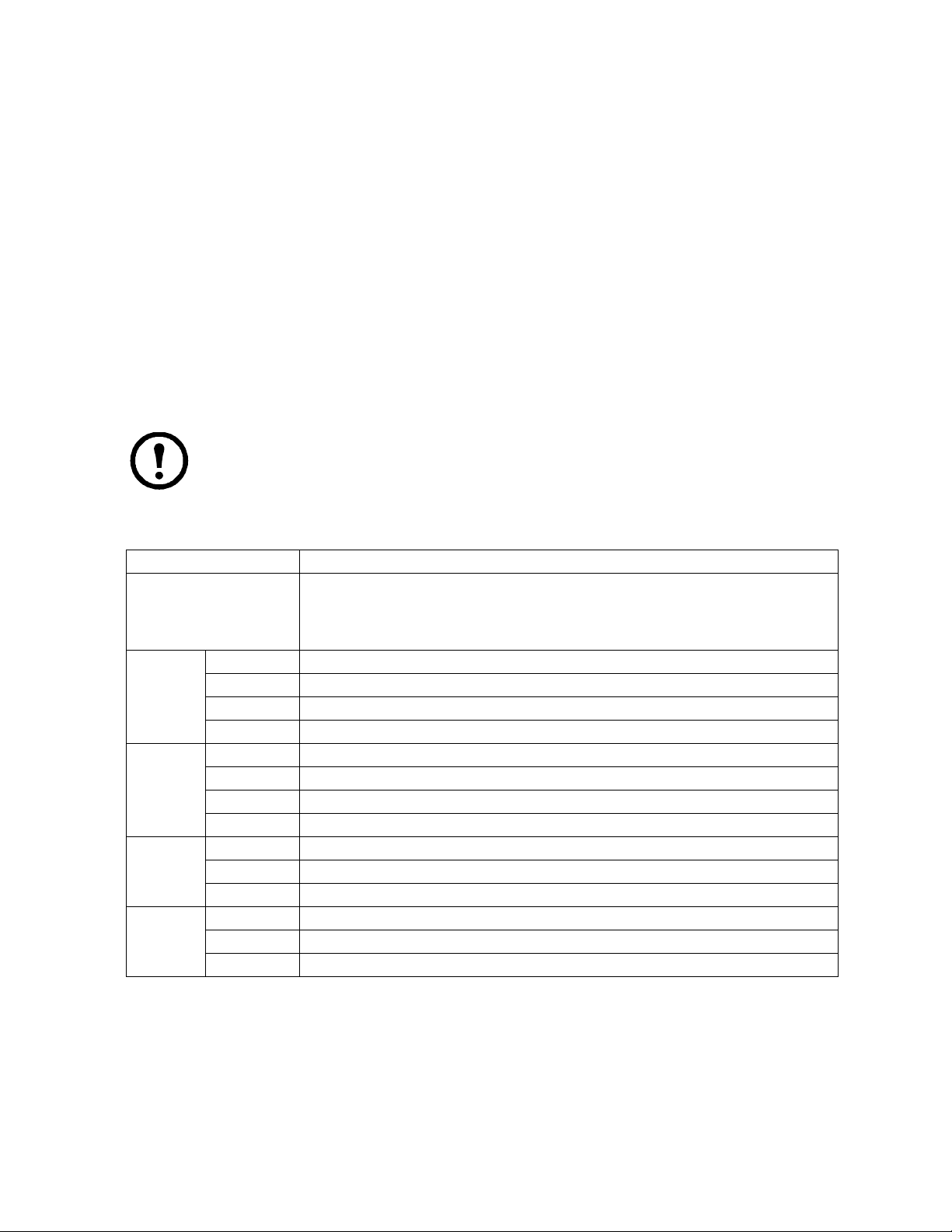
– USB: Lists USB Virtual Media devices. (Does not appear for switches that do not support the
USB Virtual Media function.) Click the icon in the row for the port you want to configure to
view the choices.
• Full Access means that the User can mount, read, and write the virtual media.
• View Only means that the user can only read already mounted virtual media data.
– Config: Permit or restrict a user's permission to make changes to a port's configuration
settings. Click the icon in the row for the port you want to configure to view the choices.
• A check mark indicates that the user has permission to make changes to the port's
configuration settings.
• An X means that the user is denied permission to make configuration changes.
– PDU: Permit or restrict the configuration and power operation of ports that have PDU devices
connected to them.
• A check mark indicates that the user has permission.
• An X means that the user does not have permission.
5. Click Save when finished. Click OK to confirm.
Note: Use Shift-Click or Ctrl-Click from any column to select a group of ports to configure.
Clicking to see the choices on any one of the selected ports causes all of them to cycle in
unison.
Filters. Expand or limit the scope of the ports that are displayed in the Name column using the five
filters at the top of the columns.
Filter Description
Name To filter the port name, enter the name then press [
correspond to the entry appear in the list.
Wildcards (? for single characters; * for multiple characters) and the keyword “or” are
supported. See page 59 for an example.
Access All All ports appear in the list.
Full Access Only ports configured as Full Access ports appear in the list.
View Only Only ports configured as View Only ports appear in the list.
No Access Only ports configured as No Access ports appear in the list.
USB All All ports appear in the list.
Full Access Only ports configured as Full Access USB ports appear in the list.
Read Only Only ports configured as Read Only USB ports appear in the list.
No Access Only ports configured as No Access USB ports appear in the list.
Config All All ports appear in the list.
Permitted Only ports configured as Permitted appear in the list.
Restricted Only ports configured as Restricted appear in the list.
PDU All All ports appear in the list.
Permitted Only ports configured as Permitted appear in the list.
Restricted Only ports configured as Restricted appear in the list.
Assigning Device Permissions From the Groups' Notebook
ENTER]. Only ports whose names
1. In the Sidebar Groups list, click the group's name or select the group's name in the main panel.
2. Click Modify to open the Groups notebook.
3. Select the Devices tab to open a screen that looks the same as the one in the User's notebook. The
settings here apply to all group members instead of just one user. Make device assignments
according to the information described under “Assigning Device Permissions From the User's
Notebook” on page 65.
KVM Switch KVM2132P, KVM2116P, KVM1116P User Manual 66
Page 79

Device Management
Device Information
The Device Management page opens with the top level (parent) KVM switch selected in the Sidebar and
Device Information selected on the menu bar.
General
The General section of the Device Information page displays the name of the selected device, its
firmware version, and information about its network configuration.
Note: The AP GUI version presents the same information as the Browser version. Scroll
through the list to see additional entries.
Environment
The lower panel displays the device's environment information.
Item Description
Power Supply
Detection
Fan Warning
Message
Fan Speed Displays fan speeds. See “Fan Location and Speed Information” on page 109.
Temperature
Warnin g
Message
Temperature Displays temperature readings from the switch's built-in sensors in Celsius or Fahrenheit. See
Power Supply 1 and Power Supply 2 icons display in gray when there is no power to the power
supply and in blue when power is present.
When enabled (there is a check in the checkbox), if there is only one source of power, a constant
warning beeps. A message displays asking for confirmation that having one power source is
intentional.
If one source of power is intended, to stop the beeping:
• Uncheck the checkbox to disable the function permanently.
• Confirm your intention in the dialog box to disable the warning temporarily. The warning
function will be back on after the next system reset.
The default for this function is enabled.
Place a check in the checkbox to enable a fan warning message. If enabled, when any fan stops
spinning the system records the event in the system log. If it is not enabled, the event will not be
recorded. The default for this function is enabled.
Note: The warning does not mean that the fan has failed, since the fans stop when the
temperature drops below the device's lower temperature setting.
Place a check in the checkbox to enable a temperature warning message. If enabled, when the
device's temperature drops below the Low threshold setting, or exceeds the High threshold
setting, the system records the event in the system log. If it is not enabled, the event will not be
recorded. The default is enabled.
“Temperature Sensor Location and Information” on page 109.
Operating Mode
Use the Operating Mode page to set working parameters.
• Force all to grayscale: Enable to change the remote displays of all devices connected to the KVM
switch to grayscale. This can speed up I/O transfer in low bandwidth situations.
• Enable Device List: Enable for the switch to appear in the Server List of WinClient or Java Client
AP. See “Windows Client AP Login” on page 20, and “Java Client AP Login” on page 21. The
switch can still be connected, but its name will not appear in the Server List if the option is not
enabled.
67KVM Switch KVM2132P, KVM2116P, KVM1116P User Manual
Page 80

• Enable First Rider Transfer: Only the first user on a bus can switch ports when enabled. Other
users on the bus cannot switch ports unless another bus is already connected to the port they
would like to access, or there is a free bus available. See “Users and Buses” on page 89 for more
information.
• Keyboard/Mouse Broadcast: Choose the setting from the drop down list.
– Keyboard Broadcast: Keystrokes will be duplicated on all attached servers currently listed in
the Sidebar when enabled.
– Mouse Broadcast: Mouse movements and clicks will be duplicated on all attached servers
currently listed in the Sidebar when enabled.
Note: 1. On a child KVM switch tiered from the parent or top level KVM switch,
only one port can perform a Keyboard/Mouse broadcast at a time.
2. For Mouse Broadcast, you and all the servers must be running the same OS, the
monitors must have the same resolution, and screens must have an identical layout.
• Console Keyboard Language: Specify which keyboard mapping is being used by the Local
Console keyboard from the drop down list.
Network
IP Installer. The IP Installer is an external Windows-based utility for assigning IP addresses to the KVM
switch. Click one of the radio buttons to select Enable, View Only, or Disable for the IP Installer utility.
See “IP Installer” on page 105 for details.
Note: If you select View Only, you can see the KVM switch in the IP Installer’s Device List,
but you cannot change the IP address. For security, it is recommended to set this to View
Only or Disable after each use.
Service Ports. As a security measure, if a firewall is being used, the Administrator can specify the port
numbers that the firewall will allow. If a port other than the default is used, users must specify the port
number as part of the IP address when they log in. If an invalid port number (or no port number) is
specified, the KVM switch will not be found.
Field Explanation
Program This is the port number for connecting with the WinClient ActiveX Viewer, WinClient AP, Java
Applet Viewer, Java Client AP, or via Virtual Media. The default is 9000.
HTTP The port number for a browser login. The default is 80.
HTTPS The port number for a secure browser login. The default is 443.
SSH The port for SSH access. The default is 22.
Telnet The port for Telnet access. The default is 23.
Note: 1. Valid entries for all Service Ports are from 1-65535.
2. Service ports cannot have the same value. Set a different value for each port.
3. If there is no firewall (on an Intranet, for example), these numbers will have no effect.
KVM Switch KVM2132P, KVM2116P, KVM1116P User Manual 68
Page 81

NIC Settings.
Redundant NIC
The KVM switch is designed with two network interfaces. If Redundant NIC is enabled (the default),
both interfaces make use of the IP address of Network Adapter 1. The second interface is usually
inactive. If there is a network failure on the first interface, the switch automatically switches to the
second interface.
Redundant NIC Enabled - Single IP Address for Both Interfaces
1. Click to put a check in the Redundant NIC checkbox.
2. Network Adapter 1 is selected in the network adapter listbox, disabling the listbox. You cannot
configure Network Adapter 2.
3. Configure the IP and DNS server addresses for Network Adapter 1 (see the sections below).
Redundant NIC Not Enabled - Two IP Addresses
If you choose not to enable the Redundant NIC function, the two NICs can be configured with separate
interfaces. Users can log into the KVM switch with either IP address.
To set up the switch with this configuration:
1. If there is a check in the Redundant NIC checkbox, click to remove it.
2. In the network adapter listbox, select Network Adapter 1.
3. Configure the IP and DNS server addresses for Network Adapter 1.
4. Select Network Adapter 2 from the network adapter list.
5. Configure the IP and DNS server addresses for Network Adapter 2.
IPv4 Settings
IP Address:
IPv4 is the traditional method of specifying IP addresses. The KVM switch can either have its IP address
assigned dynamically (DHCP), or it can be given a fixed IP address.
• For dynamic IP address assignment, select the Obtain IP address automatically radio button.
(This is the default setting.)
• To specify a fixed IP address, select the Set IP address manually radio button and fill in the
fields with values appropriate for your network.
Note: 1. If you choose Obtain IP address automatically, when the switch starts up it waits to
get its IP address from the DHCP server. If it hasn't obtained the address after one minute, it
automatically reverts to its factory default IP address (192.168.0.60.)
2. If the switch is on a network that uses DHCP to assign network addresses, and you need to
ascertain its IP address, see “IP Address Determination” on page 105, for information.
DNS Server
• For automatic DNS Server address assignment, select the Obtain DNS Server address
automatically radio button.
• To specify the DNS Server address manually, select the Set DNS server address manually radio
button, and fill in the addresses for the Preferred and Alternate DNS servers with values
appropriate for your network.
Note: Specifying the Alternate DNS Server address is optional.
69KVM Switch KVM2132P, KVM2116P, KVM1116P User Manual
Page 82

IPv6 Settings
IP Address:
IPv6 is the new (128-bit) format for specifying IP addresses. (See “IPv6” on page 106 for further
information.) The KVM switch can either have its IPv6 address assigned dynamically (DHCP), or it can
be given a fixed IP address.
• For dynamic IP address assignment, select the Obtain IP address automatically radio button.
(The default setting.)
• To specify a fixed IP address, select the Set IP address manually radio button and fill in the
fields with values appropriate for your network.
DNS Server
• For automatic DNS Server address assignment, select the Obtain DNS Server address
automatically radio button.
• To specify the DNS Server address manually, select the Set DNS server address manually radio
button, and fill in the addresses for the Preferred and Alternate DNS servers with values
appropriate for your network.
Note: Specifying the Alternate DNS Server address is optional.
Network Transfer Rate
This setting allows you to tailor the size of the data transfer stream to match network traffic conditions
by setting the rate at which the KVM switch transfers data between itself and the client computers. The
range is from 4-99999 Kilobytes per second (KBps).
Finishing
Be sure to enable Reset on exit on the Device Management > System Operation page (see “Reset on
exit” on page 94), before logging out to allow network changes to take effect without powering the
switch off and on.
ANMS
Use ANMS (Advanced Network Management Settings) to set up login authentication and authorization
management from external sources. It is organized as a notebook with two tabs, each with a series of
related panels.
Event Destination.
SMTP Settings
To have the KVM switch email reports from the SMTP server to you:
1. Enable the Enable report from the following SMTP server, and enter the IPv4 address, IPv6
address, or domain name of the SMTP server.
2. If your server requires a secure SSL connection, put a check in the My server requires secure
connection (SSL) checkbox.
3. If your server requires authentication, put a check in the My server requires authentication
checkbox, and enter the account information in the Account Name and Password fields.
4. Enter the email address where the report will be sent in the From field. Put only one email
address in the From field. It cannot exceed 64 Bytes.
5. Enter the email address (addresses) where you want the SMTP reports sent in the To field.
Note: If the report will be sent to more than one email address, separate the addresses
with a semicolon. The total cannot exceed 256 Bytes.
KVM Switch KVM2132P, KVM2116P, KVM1116P User Manual 70
Page 83

Log Server.
Important transactions that occur on the KVM switch, such as logins and internal status messages, are
kept in an automatically generated log file. See “Log” on page 90, for details on setting up the log server.
• Specify the MAC address of the computer that the Log Server runs on in the MAC address field.
• Specify the port used by the computer that the Log Server runs on to listen for log details in the
Port field. The valid port range is 1-65535. The default port number is 9001.
Note: The port number must different than the one used for the Program port.
SNMP Server. Enable to be notified of SNMP trap events:
1. Check Enable SNMP Agent.
2. Enter the IPv4 address, IPv6 address, or domain name of the computer to be notified.
3. Enter the port number. The valid port range is 1-65535.
Note: The logs that are notified of SNMP trap events are configured on the Notification
Settings page under the Log tab. See “Log Notification Settings” on page 91 for details.
Syslog Server.
To record all the events that take place on KVM switches and write them to a Syslog server:
1. Check Enable.
2. Enter the IPv4 address, IPv6 address, or domain name of the Syslog server.
3. Enter the port number. The valid port range is 1-65535.
Authentication
Disable Local Authentication.
Selecting this option disables login authentication on the KVM switch. The switch can only be accessed
using LDAP, LDAPS, MS Active Directory, RADIUS or KVM Access Management Server
authentication.
71KVM Switch KVM2132P, KVM2116P, KVM1116P User Manual
Page 84

RADIUS Settings.
To allow authentication and authorization for the KVM switch through a RADIUS server:
1. Check Enable.
2. Enter the IP addresses and service port numbers for the Preferred and Alternate RADIUS servers.
Use the IPv4 address, the IPv6 address or the domain name in the IP fields.
3. In the Timeout field, set the time in seconds that the KVM switch waits for a RADIUS server
reply before it times out.
4. In the Retries field, set the number of allowed RADIUS retries.
5. In the Shared Secret field, key in the character string that you want to use for authentication
between the KVM switch and the RADIUS Server. A minimum of 6 characters is required.
6. On the RADIUS server, Users can be authenticated with any of the following methods:
– Set the entry for the user as su/xxxx. (xxxx represents the Username given to the user when the
account was created on the KVM switch.)
– Use the same Username on both the RADIUS server and the KVM switch.
– Use the same Group name on both the RADIUS server and the KVM switch.
– Use the same Username/Group name on both the RADIUS server and the KVM switch.
Assign the same user access rights that were assigned when the User of Group was created on the KVM
switch. See “Adding Users” on page 60.
LDAP / LDAPS Authentication and Authorization Settings.
To allow authentication and authorization for the KVM switch via LDAP / LDAPS:
Item Action
Enable Put a check in the Enable checkbox to allow LDAP / LDAPS authentication and
authorization.
Type Click a radio button to specify whether to use LDAP or LDAPS.
LDAP Server IP
and Port
Admin DN Consult the LDAP / LDAPS administrator to ascertain the appropriate entry for this field. For
Admin Name Key in the LDAP administrator's username.
Password Key in the LDAP administrator's password.
Search DN Set the distinguished name of the search base. This is the domain name where the search
Timeout Set the time in seconds that the KVM switch waits for an LDAP or LDAPS server reply
Fill in the IP address and port number for the LDAP or LDAPS server.
• Use the IPv4 address, the IPv6 address or domain name in the LDAP Server field.
• For LDAP, the default port number is 389; for LDAPS, the default port number is 636.
example, the entry might look like this:
ou=kn4132,dc=aten,dc=com
starts for user names.
before it times out.
KVM Switch KVM2132P, KVM2116P, KVM1116P User Manual 72
Page 85

On the LDAP / LDAPS server, Users can be authenticated with any of the following methods:
• With MS Active Directory schema.
Note: If this method is used, the LDAP schema for MS Active Directory must be
extended. See “LDAP Server Configuration” on page 97, for details.
• Without schema - Only the Usernames used on the KVM switch are matched to the names on the
LDAP / LDAPS server. User privileges are the same as the ones configured on the switch.
• Without schema - Only Groups in AD are matched. User privileges are the ones configured for the
groups he belongs to on the switch.
• Without schema - Usernames and Groups in AD are matched. User privileges are the ones
configured for the User and the Groups he belongs to on the switch.KVM Access Server Settings
To allow authorization for the KVM switch through a KVM Access server, check Enable and enter the
Server's IP address and Service port in the appropriate fields. You can use the IPv4 address, the IPv6
address or the domain name in the Server IP field.
Note: If this function is enabled, PDU devices and Blade Servers do not appear in the
Sidebar, even if they are configured on the switch because they are managed on the server.
OOBC
In case the KVM switch cannot be accessed with the usual LAN-based methods, it can be accessed from
the switch's modem port. A modem (customer supplied) is connected to the switch using an APC adapter
cable (provided). To enable support for PPP (modem) operation, click to put a checkmark in the Enable
Out of Band Access checkbox. See “PPP Modem Operation” on page 107, for PPP setup and operation.
When Out of Band Access is enabled, the Enable Dial Back, and Enable Dial Out functions become
available.
Enable Dial Back. For security, if this function is enabled, the switch disconnects calls that dial in, and
dials back to the selected option.
Item Action
Enable Fixed Number
Dial Back
Enable Flexible Dial
Back
If enabled, the KVM switch hangs up from an incoming call and dials back to the modem
whose phone number is specified in the Phone Number field. Enter the phone number of
the modem that you want the KVM switch to dial back to in the Phone Number field.
If enabled, the modem that the KVM switch dials back does not have to be fixed. It can
dial back to any modem that is convenient for the user:
1. Enter a password that the users must specify in the Password field.
2. When connecting to the KVM switch's modem, users specify the phone number of the
modem that they want the KVM switch to dial back to as their Username, and specify
the password set in the Password field for their password.
73KVM Switch KVM2132P, KVM2116P, KVM1116P User Manual
Page 86

Enable Dial Out. For the dial out function, establish an account with an Internet Service Provider, and
use a modem to dial up to your ISP account.
Item Action
ISP Settings Specify the telephone number, account name (username), and password that you use to
connect to your ISP.
Dial Out Schedule Set the times for the KVM switch to dial out over the ISP connection.
• Every: Provides a listing of fixed times from every hour to every four hours.
Example: Select Every two hours and the KVM switch will start dialing out every two
hours beginning at 00:00.
Select Never from the list if you don't want the KVM switch to dial out on a fixed
schedule.
• Daily at will dial out once a day at a specified time. Use the hh:mm time format.
• PPP online time specifies how long the ISP connection lasts before terminating the
session and hanging up the modem. A setting of zero means it is always on line.
Emergency Dial Out If the KVM switch gets disconnected from the network, or the network goes down, this
function puts the switch on line via the ISP dial up connection.
• Choose PPP stays online until network recovery and the PPP connection to the ISP
will last until the network comes back up or the switch is able to reconnect.
• Choose PPP online time and the connection to the ISP will terminate after the time
specified. A setting of zero means it is always on line.
Dial Out Mail
Configuration
Receive email notification of problems on the devices connected to the KVM switch's
ports (see “SMTP Settings To have the KVM switch email reports from the SMTP server
to you:” on page 70).
Note: This email notification differs from the one configured under SMTP Settings. It
uses the ISP mail server rather than the internal company's mail server.
• Enter the IPv4 address, IPv6 address, or domain name of your SMTP server in the SMTP
Server IP Address field.
• Enter the email address of the person responsible for the SMTP server (or another
responsible administrator), in the Email From field.
• Enter the email address (addresses) where the report will be sent in the To f ie l d. To send
to more than one email address, separate the addresses with a comma or a semicolon.
• If your server requires a secure SSL connection, put a check in the SMTP server
requires secure connection (SSL) checkbox.
• If your server requires authentication, put a check in the SMTP server requires
authentication checkbox, enter the account name and password in the fields.
Click Save when finished.
KVM Switch KVM2132P, KVM2116P, KVM1116P User Manual 74
Page 87

Security
Login Failures
For increased security, administrators can set policies governing user log in failures. Check the Enable
checkbox (the default is enabled).
Entry Explanation
Allowed Sets the number of consecutive failed login attempts permitted from a remote computer. The
default is 5 times.
Timeout Sets the amount of time a remote computer must wait before attempting to login again after
exceeding the allowed failures. The default is 3 minutes.
Lock Client PC If enabled, after the allowed failures have been exceeded, the computer attempting to log in is
locked out. No logins from that computer will be accepted. The default is enabled.
Note: If the client computer's IP is changed, the computer will no longer be locked out.
Lock Account If enabled, after the allowed failures are exceeded, the user attempting to log in is
automatically locked out. No logins from the failed username and password will be accepted.
The default is enabled.
Note: If Login Failures is not enabled, users can attempt to log in an unlimited number of
times with no restrictions. For security purposes, enable the function and lockout policies.
Filter
IP and MAC Filtering
Control access to the KVM switch based on the IP and/or MAC addresses of the client computers
attempting to connect. A maximum of 100 IP filters and 100 MAC filters are allowed. If any filters have
been configured, they appear in the IP Filter and/or MAC Filter list boxes.
To enable, click to put a check mark in the IP Filter Enable and/or MAC Filter Enable checkbox.
• If the Include button is checked, all the addresses within the filter range are allowed access; all
other addresses are denied access.
• If the Exclude button is checked, all the addresses within the filter range are denied access; all
other addresses are allowed access.
Adding Filters
To add an IP filter:
1. Click Add to open the dialog box.
2. Specify an IPv4 or IPv6 address.
3. Enter the address you want to filter in the From: field.
– To filter a single IP address, click to put a check in the Single IP checkbox.
– To filter a continuous range of addresses, enter the end number of the range in the To: field.
Note: This description is for the AP GUI. The Browser GUI does not offer an IPv4 or
IPv6 choice. It only has From and To fields for IPv4 filtering and does not have a
checkbox to specify a single IP address. To filter a single IPv4 address, enter the same
address in both From and To fields.
4. After filling in the address, click OK.
5. Repeat the steps to filter additional IP addresses.
75KVM Switch KVM2132P, KVM2116P, KVM1116P User Manual
Page 88

To add a MAC filter:
1. Click Add to open the dialog box.
2. Specify the MAC address, then click OK.
3. Repeat the steps to filter additional MAC addresses.
IP Filter / MAC Filter Conflict. If there is a conflict between an IP filter and a MAC filter (a computer's
address is allowed by one filter but blocked by the other) then the blocking filter takes precedence (the
computer's access is blocked).
Modifying Filters. To modify a filter, select it in the IP Filter or MAC Filter list boxes and click
Modify. The Modify dialog box is similar to the Add dialog box. When it opens, delete the old
address(es) and replace with the new address(es).
Deleting Filters. To delete a filter, select it in the IP Filter or MAC Filter list box and click Delete.
Login String. The Login String entry field lets the super administrator specify a login string (in addition
to the IP address) that users must add to the IP address when they access the KVM switch with a
browser. Example: if 192.168.0.126 were the IP address, and abcdefg were the login string, the user
would have to enter: 192.168.0.126/abcdefg
Note: 1. Users must place a forward slash between the IP address and the string.
2. If no login string is specified, anyone can access the KVM switch login page using the IP
address alone, making the installation less secure.
• The following characters are allowed in the string: 0-9 a-z A-Z ~ ! @ $ & * ( ) _ - = + [ ] , . |
• The following characters are not allowed: % ^ " : / ? # \ ' { } ; ' < > [Space]
• Compound characters (É Ç ñ ... etc.)
For security purposes, it is recommended that the string be changed occasionally.
Account Policy
System administrators can set policies governing usernames and passwords.
Entry Explanation
Minimum Username
Length
Minimum Password
Length
Password Must
Contain At Least
Disable Duplicate
Login
Sets the minimum number of characters required for a username. Acceptable values are
from 1-16. The default is 3.
Sets the minimum number of characters required for a password. Acceptable values are
from 0-16. A setting of 0 means that no password is required. Users can login with only a
Username. The default is 3.
Checking any item in this section requires users to include at least one uppercase letter,
one lowercase letter or one number in their password.
Note: This policy only affects user accounts created after this policy has been enabled,
and password changes to existing user accounts. Users accounts created before the policy
is enabled, and existing passwords that have not been changd, are not affected.
Check to prevent users from logging in with the same account at the same time.
KVM Switch KVM2132P, KVM2116P, KVM1116P User Manual 76
Page 89

Encryption
Fexible encryption alternatives for keyboard/mouse, video, and virtual media data let you choose any
combination of DES; 3DES; AES; RC4; or a Random cycle of any or all of them. Enabling encryption
affects system performance. No encryption offers the best performance. The greater the encryption the
greater the adverse effect. If you enable encryption, performance considerations are:
• RC4 offers the least impact on performance; DES is next; then 3DES or AES.
• The RC4 + DES combination offers the least impact of any combination.
Mode
Item Explanation
Enable ICMP If ICMP is enabled, the KVM switch can be pinged. If it is not enabled, the device cannot be
pinged. The default is Enabled.
Enable Multiuser
Operation
Enable Virtual Media
Write Operation
Enable Local Virtual
Media
Browser Service Enabling allows the administrator to restrict browser access to the KVM switch. After
Disable
Authentication
Enabling Multiuser Operation permits up to 32 users to log in at the same time to share the
remote bus. If not enabled, only one user can log in at a time. The default is Enabled.
Enabling Virtual Media Write Operation allows redirected virtual media devices on a user's
system to send data to a remote server, as well as being able to have data from the remote
server written to them.
Enabling Local Virtual Media allows USB storage peripherals (CD/DVD, HD, flash drives,
etc.) connected to the KVM switch to appear and act as if installed on a remote system.
checking Browser Service, select the degree of restriction from the list.
• Disable Browser: no browser access is permitted.
• Disable HTTP: browser access is permitted, but the switch must be accessed with an
HTTPS URL.
• Disable HTTPS: browser access is permitted, but users must access the switch with an
HTTP URL.
If checked, no authentication procedures check users attempting to log in. Users gain
Administrator access to the KVM switch by entering their username and password.
Note: Enabling this setting creates an extremely dangerous security condition, and should
only be used under very special circumstances.
77KVM Switch KVM2132P, KVM2116P, KVM1116P User Manual
Page 90

Private Certificate
When logging in over a secure (SSL) connection, a signed certificate is used to verify that the user is
logging in to the intended site. For enhanced security, the Private Certificate section allows you to use
your own private encryption key and signed certificate, rather than the default certificate.
There are two methods for establishing your private certificate:
• Generating a Self-Signed Certificate
To create your own self-signed certificate, free utilities are available for download over the web.
See “Self-Signed Private Certificates” on page 112 for more information.
• Obtaining a CA Signed SSL Server Certificate
For the greatest security, a third party certificate authority (CA) signed certificate is
recommended. To obtain a third party signed certificate, go to a CA (Certificate Authority)
website to apply for an SSL certificate. After the CA sends you the certificate and private
encryption key, save them to a convenient location on your computer.
• Importing the Private Certificate
To import the private certificate:
1. Click Browse to the right of Private Key, browse to the location of your private encryption key
file and select it.
2. Click Browse to the right of Certificate, browse to the location of your certificate file and select
it.
3. Click Upload to complete the procedure.
Note: 1. Click Restore Default to returns the device to using the default certificate.
2. Both the private encryption key and the signed certificate must be imported at the
same time.
KVM Switch KVM2132P, KVM2116P, KVM1116P User Manual 78
Page 91

Certificate Signing Request
The Certificate Signing Request (CSR) is located under Device Management >Security >Private
Certification section. The Certificate Signing Request (CSR) section provides an automated way to
obtain and install a CA signed SSL server certificate. The KVM switch supports 1024-bit certificates
only in .cer format of x509 type.
To perform this operation:
1. Click Create CSR to open the dialog box.
2. Fill in the form with valid entries for your site. There are no unacceptable characters.
Information Max Characters Example
Country 2 letter code US
State or Province 32 Missouri
Locality 32 St. Louis
Organization 64 Your Company, Ltd.
Unit 32 Techdoc Department
Common Name 32 mycompany.com
Note: The domain name of the site must be exact for the certificate
is to be valid. If the domain name is www.mycompany.com, and
only mycompany.com is specified, the certificate will not be valid.
Email Address 64 administrator@yourcompany.com
3. Click Create when finished (all fields are required). A self-signed certificate based on the
information just provided is now stored on the KVM switch.
4. Click Get CSR, and save the certificate file (csr.cer) to your computer. This is the file given to
the third party CA to apply for their signed SSL certificate.
5. After the CA sends you the certificate, save it to a convenient location on your computer. Click
Browse to locate the file; then click Upload to store it on the KVM switch.
Note: When the file is uploaded, the KVM switch checks the file to make sure the
specified information still matches. If it does, the file is accepted, if not, it is rejected.
To remove the certificate (Example: replacing it due to a domain name change), click Remove CSR.
Date/Time
The Date/Time dialog page sets the KVM switch time parameters according to the information below.
Time Zone.
• Choose from the Time Zone list the city that corresponds to the location of the KVM switch.
• If your country or region employs Daylight Saving Time (Summer Time), check the
corresponding checkbox.
79KVM Switch KVM2132P, KVM2116P, KVM1116P User Manual
Page 92

Date.
• Select the month from the list.
• Click < or > to move backward or forward by one year increments.
• In the calendar, click on the day.
• To set the time, use the 24 hour HH:MM:SS format.
• Click Set to save your settings.
Network Time.
To automatically sychronize the time to a network time server:
1. Check the Synchronize with NTP Server checkbox.
2. Select your preferred time server from the list or check the Preferred custom server IP checkbox,
and enter the IPv4 address, IPv6 address, or domain name of the time server.
3. If you want to configure an alternate time server, check the Alternate time server checkbox, and
repeat step 2 for the alternate time server entries.
4. Enter the number of days between synchronization procedures.
5. If you want to synchronize immediately, click Update Using NTP Now.
KVM Switch KVM2132P, KVM2116P, KVM1116P User Manual 80
Page 93

PDU Devices
Configuration Page
Select a PDU device in the Sidebar to open its Configuration page.
81KVM Switch KVM2132P, KVM2116P, KVM1116P User Manual
Page 94
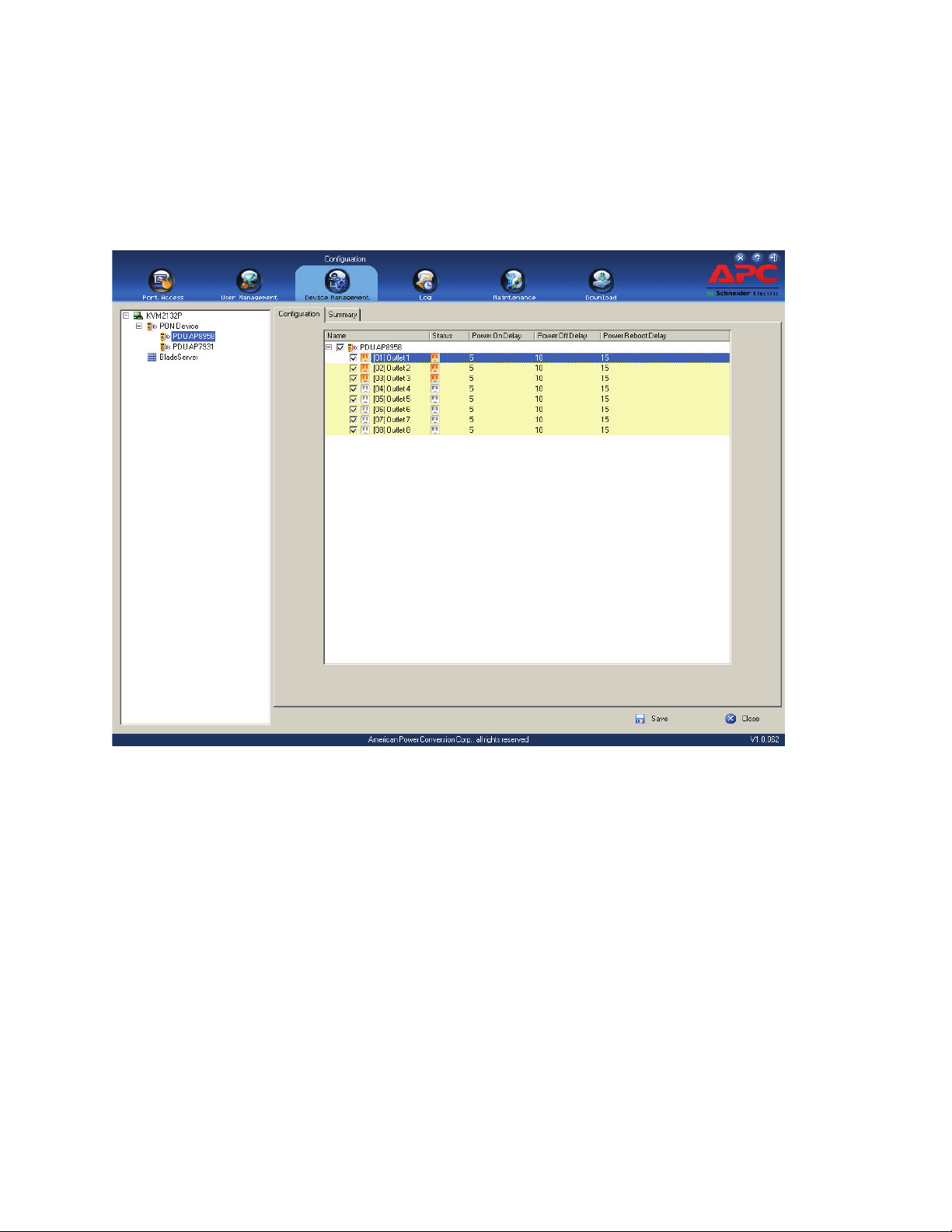
Outlet Configuration
• Click on a PDU to open a list of choices.
• Click to put a check mark in front of the outlets to be configured. Change the setting for any of the
selected outletsand each of the selected outlets gets the new setting.
• To select all of the outlets, check the box in front of the PDU’s name. Change the setting for any of
the outlets and all of the outlets get the new setting.
Configure Outlet Time Delay
1. In the Device Management page, select the PDU.
2. Change delay settings (seconds) by clicking on the numbers. Put check marks in the boxes in
front of the outlets in the list to apply the same setting to all selected.
KVM Switch KVM2132P, KVM2116P, KVM1116P User Manual 82
Page 95

Port Operation
After logging in, the KVM switch opens to the Port Access tab's Connections page, with the first KVM
switch selected in the sidebar.
Note: 1. The WinClient and Java Client AP programs have a hidden Control Panel at the
upper center of the screen that becomes visible when you move the mouse over it. The
Browser's Control Panel only appears after you switch to a port.
Connecting to a Port
All the devices, ports, and outlets that a user is permitted to access are listed in the Sidebar at the left of
the page.
• To connect to a port when a device is selected in the Sidebar:
Double click its icon in the Sidebar, double click anywhere on its line entry in the main central
panel, or select it in the main panel and click Connect at the bottom right of the page.
• To connect to a port when the port is selected in the Sidebar, click Connect at the right of the
Status panel (see “Status” on page 41).
Once switched to a port, its screen displays on your monitor, and your keyboard and mouse input affects
the remote server.
Port Toolbar
The switch provides a toolbar to help with port switching operations from within the captured port. To
open the toolbar, tap the GUI Hotkey (Scroll Lock is the default), twice. The toolbar opens at the upper
left corner of the screen.
Depending on the settings selected for ID Display, the Port Number and/or the Port Name display at the
right of the toolbar.
When the toolbar displays, mouse input is confined to the toolbar area and keyboard input has no effect
on the server connected to the port. To carry out server operations, close the toolbar by clicking its X
icon.
To return to the Port Access Connections page, click the icon, or tap the GUI hotkey again.
Note: 1. Toolbar transparency can be adjusted (see “Video Settings” on page 30).
2. The toolbar functions and icons are also incorporated in the Control Panel. Functions
enabled in the Control Panel can be disabled the Toolbar. To recall the Port Access
Connections page when there is no Toolbar, tap the GUI hotkey twice.
83KVM Switch KVM2132P, KVM2116P, KVM1116P User Manual
Page 96

Toolbar icons
Icon Purpose
Click to skip to the first accessible port on the entire installation without recalling the Port Access
page.
Click to skip to the first accessible port previous to the current one without recalling the Port Access
page.
Click to begin Auto Scan Mode. The KVM switch automatically switches among the ports selected for
Auto Scanning with the Filter function. This allows activity monitor without switching among them
manually.
Click to skip from the current port to the next accessible one, without having to recall the Port Access
page.
Click to skip from the current port to the last accessible port on the entire installation without recalling
the Port Access page.
Click to recall the Port Access page.
Click to close the toolbar.
Click to invoke Panel Array Mode.
Not available on KVM1116P at local console
Click to cycle through the Adapter cable choices (Short, Medium, Long) used to connect the device to
the switch. Choice depends on the length of Cat 5e cable used for the connection. The line length on
the icon changes to indicate the selection.
Toolbar Hotkey Port Switching
When the toolbar is displayed, hotkeys can be used to provide KVM focus to a port directly from the
keyboard.
• Go directly to a port by entering its port number and clicking Enter.
• Auto Scanning
• Skip Mode Switching
The hotkeys are A and P for Auto Scanning and the Arrow Keys for Skip Mode.
Note: 1. The toolbar must be visible for hotkey operations to work.
2. To use the keys designated as hotkeys for normal purposes, close the toolbar.
Auto Scanning
The Scan function switches at regular intervals among all ports accessible to the currently logged on user
to automatically monitor activity. Users can also limit the number of ports scanned with the Filter
function of the Sidebar. See “Scan” on page 40, and “Filter” on page 40, for more details.
• Setting the Scan Interval: The amount of time Auto Scan dwells on each port is set with the Scan
Duration setting (page 51).
• Invoking Auto Scan: With the toolbar open, tap the A key. Auto Scan cycles through the ports in
order, starting at the first port on the installation. An S appears in front of the Port ID Display to
indicate that the port is being accessed under Auto Scan Mode.
KVM Switch KVM2132P, KVM2116P, KVM1116P User Manual 84
Page 97

• Pausing Auto Scan: Pause scanning to focus on a particular server by pressing P. While Auto
Scanning is paused, the S in front of the Port ID blinks On and Off.
Pausing to keep the focus on a particular server can be more convenient than exiting Auto Scan
Mode because when scanning resumes, it starts where it left off. If you exit and then restart Auto
Scan Mode, the scanning starts over from the very first server on the installation.
To Resume Auto Scanning after a pause, press any key except [
• Exiting Auto Scan: While Auto Scan Mode is running, ordinary keyboard functions are
suspended. Exit Auto Scan Mode in order to regain normal control of the keyboard. To exit Auto
Scan Mode press [
ESC] or the [SPACEBAR]. Auto Scanning stops when you exit Auto Scan Mode.
ESC] or the [SPACEBAR].
Skip Mode
Switch ports in order to monitor the servers manually. Dwell on a particular port for as long as needed as
opposed to Auto Scanning, which automatically switches after a fixed interval. The Skip Mode hotkeys
are the four Arrow keys. Their operation is explained in the table below:
Icon Purpose
Left Skips from the current port to the first accessible port previous to it.
Right Skips from the current port to the first accessible port that comes after it.
Up Skips from the current port to the very first accessible port on the installation.
Down Skips from the current port to the very last accessible port on the installation.
Recalling the Port Access Page
To dismiss the toolbar and bring back the Port Access page:
• Tap the GUI Hotkey once.
• From the toolbar, click the icon that recalls the Port Access page (see “Toolbar icons” on page 84).
When the toolbar closes, the Port Access Page opens.
GUI Hotkey Summary Table
The table presents a summary of GUI Hotkey actions after you have accessed a port. See “User
Preferences” on page 51 to set the GUI Hotkey.
To D o T h i s
Open the Toolbar Click the GUI Hotkey twice
Open the Port
Access Page
The Toolbar is open Click the GUI Hotkey once
The Toolbar is not open Click the GUI Hotkey three times
85KVM Switch KVM2132P, KVM2116P, KVM1116P User Manual
Page 98

Keyboard Emulation
Mac Keyboard
The PC compatible (101/104 key) keyboard can emulate the functions of the Mac keyboard. The
emulation mappings are listed in the table below.
PC Keyboard Mac Keyboard
[SHIFT]Shift
CTRL]Ctrl
[
[CTRL] [1]
TRL] [2]
[C
TRL] [3]
[C
[C
TRL] [4]
LT]
[A
[PRINT SCREEN]
[SCROLL LOCK]
Alt
F13
F14
=
[ENTER]
[BACKSPACE]
[INSERT]
[CTRL] F15
Return
Delete
Help
Note: When using key combinations, press and release the first key (
release the activation key.
CTRL), then press and
KVM Switch KVM2132P, KVM2116P, KVM1116P User Manual 86
Page 99

Sun Keyboard
The PC compatible (101/104 key) keyboard can emulate the functions of the Sun keyboard when the
Control key [Ctrl] is used in conjunction with other keys. The corresponding functions are shown below.
PC Keyboard Sun Keyboard
[CTRL] [T]
[CTRL] [F2]
[CTRL] [F3]
[CTRL] [F4]
[CTRL] [F5]
[CTRL] [F6]
[CTRL] [F7]
[CTRL] [F8]
[CTRL] [F9]
[CTRL] [F10]
[CTRL] [1]
Stop
Again
Props
Undo
Front
Copy
Open
Paste
Find
Cut
[C
TRL] [2]
TRL] [3]
[C
[CTRL] [4]
[CTRL] [H]
Help
Compose
Meta
Note: When using key combinations, press and release the first key (
release the activation key.
CTRL), then press and
87KVM Switch KVM2132P, KVM2116P, KVM1116P User Manual
Page 100

Panel Array Mode
Click the Panel icon on the toolbar to start Panel Array Mode. The screen is divided into up to 42 panels:
• Each panel represents one of the switch's ports beginning with Port 1 at the upper left, and going
from left to right; top to bottom.
• Click Show More Ports, and Show Fewer Ports symbols on the panel array toolbar to select the
number of panels in the array.
• Panel Array scans each of the ports previously selected with the Filter function (see “Filter” on
page 40). The panel’s border is highlighted while that port is the focus of the scan.
• Only ports accessible to the user are displayed. Blank panels display for ports that are not
accessible.
• If the server connected to a port is on line the screen displays in the panel, otherwise the panel is
blank.
• Move the mouse over a panel to display information about the port (port name, online status, port
access status, and resolution).
• Access a server connected to a port by moving the mouse pointer over its panel and clicking. You
switch to the server exactly as if you had selected it from the Port Access page.
Panel Array Toolbar
The panel array toolbar provides shortcut navigation and control of the panel array. The toolbar can be
dragged anywhere on the screen. Move the mouse over an icon to show a "tooltip" ( a short description
of the icon's function).
Icon Purpose
Click and drag to move the toolbar.
Note: This icon is only available with the Windows Clients. To move the Java Client
toolbars, click on any empty space and drag.
Pause panel scanning, leaving the focus on the panel that currently has it.
Move back four panels.
Move to the previous panel.
Move to the next panel.
Move ahead four panels.
Show More Ports: Increase the number of panels in the array.
Show Fewer Ports: Decrease the number of panels in the array.
Toggle 4/3 aspect ratio.
Exit Panel Array mode.
KVM Switch KVM2132P, KVM2116P, KVM1116P User Manual 88
 Loading...