

Schneider Electric Erie VM PopTop Series Installation Instructions
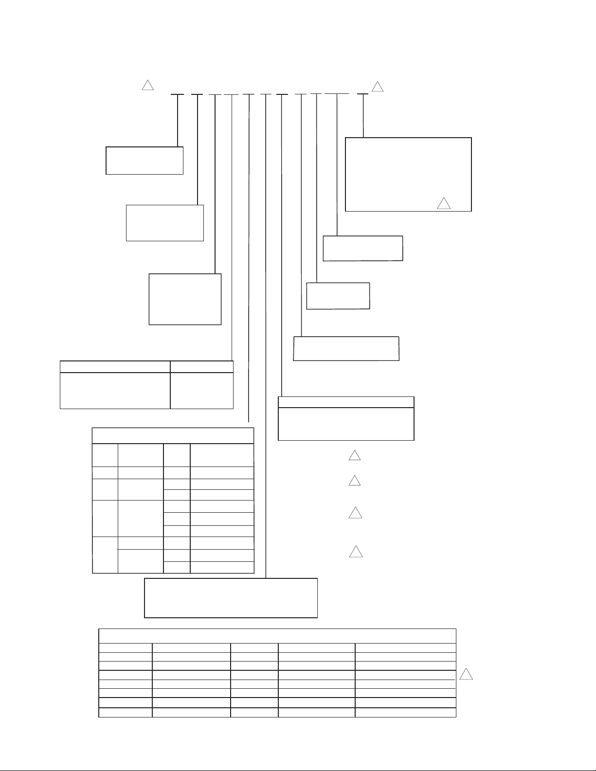
Part Numbering System
Modulating Spring and Non-Spring Return Zone Valves
1
V M X X X X X X 3 A 00 X
Body Type
M = Modulating
Configuration
2 = 2-Way
3 = 3-Way
2 = 1/2"
3 = 3/4"
4 = 1"
5= 1-1/4"
Connection Type Availability
1 = Sweat 1/2", 3/4", 1", 1-1/4"
2 = Threaded NPT 1/2", 3/4", 1"
3 = Threaded Rp (Metric) 1/2", 3/4", 1"
5 = SAE Flare 1/2"
CV Size
1/2" 1, 2, 3, 5
1 = 1.0
1/2" 1, 2, 3, 5
2 = 2.0
3/4" 1, 2, 3
1/2" 1, 2, 3, 5
3 = 4.0
3/4" 1, 2, 3
1" 1
3/4" 1, 2, 3
7 =
1" 1, 2, 3
1-1/4" 1
7.5
8.0
T = Three-wire Floating
P = Proportional, 0-10 Vdc, 0-5 Vdc,
5-10 Vdc or 4-20 mA, Jumper Selectable
Valve Size
Size Connection Type
Actuator Type
2
Options
Non-Spring Return Actuators
0 = No Options
T = Three-Wire Signal Time-Out
Spring Return Actuators
T = Time-Out
Electrical Leads
00 = No leads
Voltage
A = 24 Vac Only
Temperature Ratings
3 = General Temperature
Action
1 = Spring Return Normally closed
2 = Spring Return Normally opened
3 = Non-Spring Return
1
When ordering valve body only: use the first
six positions to configure the valve.
2
When ordering actuator only: use the last
seven positions to configure the actuator.
Prefex with the letter "A."
3
This feature is standard
for spring return actuators.
It must be included in the
part number.
4
Should not be used with thermostats/
controllers unless they have a
timeout feature.
3
Available Actuators
Part Number
AT13A00T
AT23A00T
AT33A000
AT33A00T
AP13A000
AP23A000
AP33A000
2 © Copyright 2013 Schneider Electric All Rights Reserved. F-27013-8
Action
Spring Return
Spring Return
Non-Spring Return
Non-Spring Return
Spring Return
Spring Return
Non-Spring Return
Position
N.C.
N.O.
N.C.
N.O.
Actuator Type
Three Wire Floating
Three Wire Floating
Three Wire Floating
Three Wire Floating
Proportional
Proportional
Proportional
Option
With Time-Out
With Time-Out
None
With Time-Out
None
None
None
4
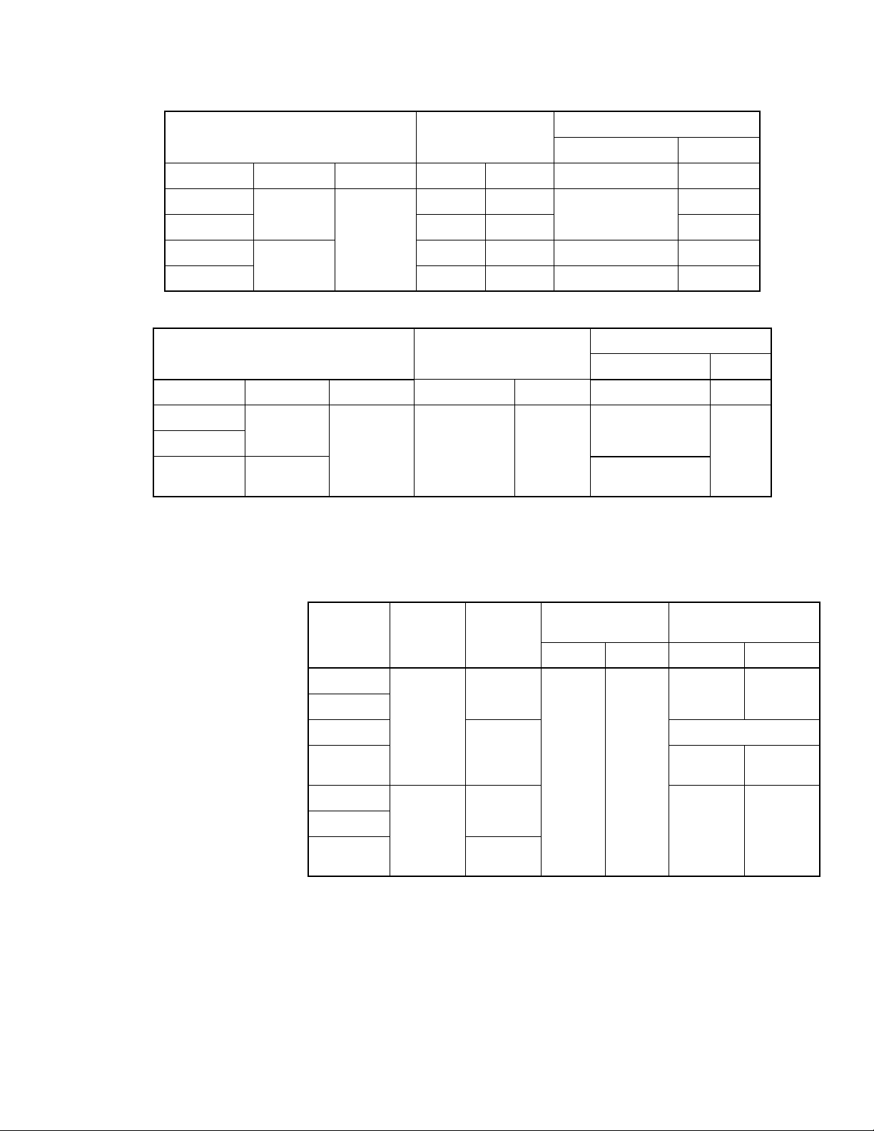
SPECIFICATIONS
Inputs
Floating Actuator Control Circuit, Max.
Powerup Inrush
a
Running
Series Action Vac mA VA VA VA
Total Actuator, Max.
AT13A00T
AT23A00T 24 0.6 1.9
Spring
Return
24 Vac
24 0.6
10
1.9
+25%/-15%
AT33A000
AT33A00T – – 1.2 1.2
a Transformer must be sized for Powerup Inrush
Non- Spring
Return
50/60 Hz
–– 1.0 1.0
Total Actuator, Max.
Proportional Actuator Control Circuit, Max.
Powerup Inrush
a
Running
Series Action VAC Range Rin VA VA
AP13A000
AP23A000
AP33A000
a Transformer must be sized for Powerup Inrush
b Factory supplied. Actual range is 1-9 Vdc.
Spring
Return
Non-Spring
Return
24 Vac
+25%/-15%
50/60 Hz
b
0-10 VDC
or
0-5 VDC or
5-10 VDC or
4-20 mA
>200K
>200K
>200K
300
10
1.7
1.7
Outputs
Timing:
Nominal Stroke
Series Mode Action
Time
60 Hz 50 Hz 60 Hz 50 Hz
AT13A00T
AT23A00T
AT33A000
Floating
Spring
Return
3 min.
Non-Spring
AT33A00T
AP13A000
AP23A000
AP33A000
Modulating
Return
Spring
Return
Non-Spring
Return
2 min. 30
sec.
3 min.
3 min.
± 30 sec.
2 min.
45 sec.
Mechanical:
Action, T series: Direct acting.
P series: Direct acting (valve opens port B with increase in signal.) Field
selectable reverse acting.
Manual Override, Allows manual positioning.
Operating Pressure Limits, 400 psi (2758 kPa) static pressure.
Material,
Actuator: High temperature plastic.
Valve: Body: Forged brass; stem: nickel-plated/chrome-plated brass; seat:
brass, plug/paddle: high temperature thermoplastic/rubber.
Flow Characteristic, 1.0 to 4.0 Cv: equal percentage. 7.0/8.0 Cv: linear.
Total Run Tim e
3 min.
36 sec.
no delay
na
3 min.
18 sec.
F-27013-8 © Copyright 2013 Schneider Electric All Rights Reserved. 3

Environment
Ambient Temperature Limits:
Shipping & Storage, -40 to 158°F (-40 to 70°C)
Operating, 35 to 125°F (2 to 52°C).
Fluid, 32 to 200× F (0× to 93× C) (not steam rated).
Humidity: 5 to 95% RH, non-condensing.
Seat Leakage: ANSI class IV (0.01%)
Shipping Weight: 1.9 lbs (860 g), actuator and valve body.
Location: NEMA Type 1.
Agency Listings (Actuator Only):
UL873: Underwriters Laboratories (File #E9429 Category Temperature Indicating and
Regulating Equipment) Class 2.
CUL: UL Listed for use in Canada by Underwriters Laboratory. Canadian Standards C22.2
No. 24.
European Community: CE Approved.
Australia: This product meets the requirements to bear the C-Tick Mark according to the
terms specified by the Communications Authority under the Radio Communications Act of
1992.
Table-1 Flow Coefficients & Maximum Close-Off Differential Pressure.
Valve
Size in.
Connection Type
Flow Coefficient
Cv (kv)
Non-Spring
Operating Mode
(Driven Close)
Maximum Close-Off DP, PSI (kPa)
Spring Return
Operating Mode
(Driven Closed)
Spring Return
Power Failure Mode*
(Spring Close) PSID
1/2 NPT, SW, SAE, Rp 1.0 (0.9) 50 (344) 50 (344) 50 (344)
1/2 NPT, SW, SAE, Rp
2.0 (1.8) 50 (344) 50 (344) 20 (138)
3/4 NPT, SW, Rp
1/2 NPT, SW, SAE, Rp
4.0 (3.5) 35 (241) 35 (241) 20 (138)3/4 NPT, SW, SAE, Rp
1SW
3/4 NPT, SW, Rp 7.5 (6.5) 35 (241) 35 (241) 15 (103)
1SW, Rp
8.0 (6.9) 35 (241) 35 (241) 15 (103)
1-1/4 SW
*If valve is driven closed before a power failure, he "operating mode" close-off pressures apply.
Valve Body Legend
NPT — Threaded
SW — Sweat
SAE — Society Automotive Engineers.
Rp—"Metric" Threaded
4 © Copyright 2013 Schneider Electric All Rights Reserved. F-27013-8
 Loading...