

Page 1
Enerlin’X IFE
Ethernet Switchboard Server
User Guide
DOCA0084EN-09
01/2021
www.se.com
Page 2

Legal Information
The Schneider Electric brand and any trademarks of Schneider Electric SE and its
subsidiaries referred to in this guide are the property of Schneider Electric SE or its
subsidiaries. All other brands may be trademarks of their respective owners.
This guide and its content are protected under applicable copyright laws and
furnished for informational use only. No part of this guide may be reproduced or
transmitted in any form or by any means (electronic, mechanical, photocopying,
recording, or otherwise), for any purpose, without the prior written permission of
Schneider Electric.
Schneider Electric does not grant any right or license for commercial use of the guide
or its content, except for a non-exclusive and personal license to consult it on an "as
is" basis. Schneider Electric products and equipment should be installed, operated,
serviced, and maintained only by qualified personnel.
As standards, specifications, and designs change from time to time, information
contained in this guide may be subject to change without notice.
To the extent permitted by applicable law, no responsibility or liability is assumed by
Schneider Electric and its subsidiaries for any errors or omissions in the informational
content of this material or consequences arising out of or resulting from the use of the
information contained herein.
Page 3

Table of Contents
Safety Information ......................................................................................5
About the Book...........................................................................................7
IFE Server Presentation.............................................................................9
Introduction..............................................................................................10
Intelligent Modular Unit ............................................................................. 11
Hardware Description ............................................................................... 15
EcoStruxure Power Commission Software ................................................. 19
Schematics with MasterPact MTZ Circuit Breakers .....................................21
Schematics with MasterPact NT/NW and ComPact NS Circuit
Breakers .................................................................................................. 23
Schematics with ComPact NSX Circuit Breakers......................................... 27
Technical Characteristics .......................................................................... 32
Firmware Update......................................................................................34
Schneider Electric Green Premium
IFE Server Webpages.............................................................................. 37
IFE Interface ............................................................................................38
Configuration & Settings Webpages...........................................................46
Monitoring Webpges................................................................................. 80
Control Webpages.................................................................................... 87
Diagnostics Webpages ............................................................................. 92
Ethernet Switchboard Server
™
Ecolabel ............................................ 35
Access to IFE Webpages ....................................................................39
User Interface Layout.......................................................................... 42
Webpage Description.......................................................................... 44
General.............................................................................................. 47
Date and Time ....................................................................................48
Time Zone..........................................................................................50
Ethernet Configuration (Dual Port) .......................................................51
IP Configuration.................................................................................. 52
Modbus TCP/IP Filtering ..................................................................... 54
Modbus Serial Line .............................................................................55
Email Server Configuration.................................................................. 56
Email Events ......................................................................................58
Device List ......................................................................................... 65
Device Logging................................................................................... 70
Device Log Export............................................................................... 72
SNMP Parameters..............................................................................74
Preferences........................................................................................ 75
Advanced Services Control..................................................................76
User Accounts .................................................................................... 77
Webpage Access................................................................................79
Real Time Data...................................................................................81
Device Logging................................................................................... 83
Device Control.................................................................................... 88
Set Device Time .................................................................................91
Statistics ............................................................................................ 93
Device Identification............................................................................ 96
IMU Information.................................................................................. 97
Read Device Registers........................................................................98
DOCA0084EN-09 3
Page 4

Ethernet Switchboard Server
Communication Check ........................................................................ 99
IO Readings ..................................................................................... 100
Maintenance Webpages ......................................................................... 101
Indicators ......................................................................................... 102
Restore the Smartlink Modbus Devices .............................................. 103
Appendices .............................................................................................. 104
Appendix A - List of IFE Supported Devices.............................................. 105
List of IFE Supported Device Types.................................................... 106
4 DOCA0084EN-09
Page 5
Safety Information Ethernet Switchboard Server
The addition of this symbol to a “Danger” or “Warning” safety label indicates that an
electrical hazard exists which will result in personal injury if the instructions are not
followed.
This is the safety alert symbol. It is used to alert you to potential personal injury
hazards. Obey all safety messages that follow this symbol to avoid possible injury or
death.
DANGER indicates a hazardous situation which, if not avoided, will result in death or serious
injury.
!
DANGER
WARNING indicates a hazardous situation which, if not avoided, could result in death or
serious injury.
WARNING
!
CAUTION indicates a hazardous situation which, if not avoided, could result in minor or
moderate injury.
CAUTION
!
NOTICE is used to address practices not related to physical injury.
NOTICE
Safety Information
Important Information
Read these instructions carefully, and look at the equipment to become familiar
with the device before trying to install, operate, service, or maintain it. The
following special messages may appear throughout this documentation or on the
equipment to warn of potential hazards or to call attention to information that
clarifies or simplifies a procedure.
Please Note
Electrical equipment should be installed, operated, serviced, and maintained only
by qualified personnel. No responsibility is assumed by Schneider Electric for any
consequences arising out of the use of this material.
A qualified person is one who has skills and knowledge related to the construction
and operation of electrical equipment and its installation, and has received safety
training to recognize and avoid the hazards involved.
DOCA0084EN-09 5
Page 6
Ethernet Switchboard Server Safety Information
CYBERSECURITY SAFETY NOTICE
WARNING
POTENTIAL COMPROMISE OF SYSTEM AVAILABILITY, INTEGRITY, AND
CONFIDENTIALITY
• Change default passwords at first use to help prevent unauthorized access
to device settings, controls, and information.
• Disable unused ports/services and default accounts to help minimize
pathways for malicious attackers.
• Place networked devices behind multiple layers of cyber defenses (such as
firewalls, network segmentation, and network intrusion detection and
protection).
• Use cybersecurity best practices (for example, least privilege, separation of
duties) to help prevent unauthorized exposure, loss, modification of data and
logs, or interruption of services.
Failure to follow these instructions can result in death, serious injury, or
equipment damage.
6 DOCA0084EN-09
Page 7

About the Book Ethernet Switchboard Server
About the Book
Document Scope
The aim of this document is to provide the users, installers, and the maintenance
personnel with the technical information and procedure needed to access and
maintain the IFE Ethernet switchboard server webpages.
Validity Note
The information contained in this document is likely to be updated at any time.
Schneider Electric strongly recommends that you have the most recent and up-todate version available on www.se.com/docs.
The technical characteristics of the devices described in the present document
also appear online. To access the information online, go to the Schneider Electric
home page www.se.com/ww/en/download/.
The characteristics that are described in the present document should be the
same as those characteristics that appear online. In line with our policy of constant
improvement, we may revise content over time to improve clarity and accuracy. If
you see a difference between the document and online information, use the online
information as your reference.
Related Documents
Title of Documentation Reference Number
Enerlin’X IFE - Ethernet Switchboard Server - Instruction Sheet QGH13473
MasterPact MTZ Modbus Communication Guide DOCA0105EN
MasterPact NT/NW, ComPact NS Modbus Communication Guide DOCA0054EN
ComPact NSX Modbus Communication Guide DOCA0091EN
ULP System (IEC Standard) - User Guide DOCA0093EN
Enerlin'X IFE Server Firmware Release Note DOCA0148EN
You can download these technical publications and other technical information
from our website at www.se.com/ww/en/download/.
DOCA0084EN-09 7
Page 8

Page 9

IFE Server Presentation
What’s in This Part
Introduction.................................................................................................... 10
Intelligent Modular Unit................................................................................... 11
Hardware Description ..................................................................................... 15
EcoStruxure Power Commission Software .......................................................19
Schematics with MasterPact MTZ Circuit Breakers ........................................... 21
Schematics with MasterPact NT/NW and ComPact NS Circuit Breakers............. 23
Schematics with ComPact NSX Circuit Breakers ..............................................27
Technical Characteristics ................................................................................32
Firmware Update ........................................................................................... 34
Schneider Electric Green Premium
Ethernet Switchboard Server
™
Ecolabel ..................................................35
DOCA0084EN-09 9
Page 10

Ethernet Switchboard Server Introduction
Introduction
Overview
The IFE Ethernet switchboard server (or IFE server) enables an intelligent
modular unit (IMU) with a ComPact
to be connected to an Ethernet network. Each circuit breaker has its own IFE
server and a corresponding IP address.
The IFE server with part number LV434002 is an Ethernet switchboard server for
ComPact, PowerPact, and MasterPact circuit breakers and a server for ModbusSL (serial line) connected devices.
IFE Server Features
The main features of IFE server are:
™
, PowerPact™, or MasterPact™circuit breaker
NOTE: The IFE interface with part number LV434001 completely replaces the
IFE interface with part number LV434010. The LV434001 comes with the real
time clock (RTC) feature and allows ULP connections up to 20 m (65.6 ft) with
the MasterPact MTZ circuit breakers (LV434010 had a theoretical limitation of
5 m (16.4 ft) over the life of the IFE interface).
• Dual Ethernet port for simple daisy chain connection
• Device profile web service for discovery of the IFE server on the local area
network (LAN)
• ULP compliant for location of the IFE server in the switchboard
• Ethernet interface for ComPact, PowerPact, and MasterPact circuit breakers
• Server for Modbus-SL connected devices
• Embedded setup webpages
• Embedded monitoring webpages
• Embedded control webpages
• Built-in email alarm notification for circuit breaker connected to IFE server.
NOTE: The built-in switch of IFE server does not support the ring topology as
it does not have the feature of the loop back protection.
10 DOCA0084EN-09
Page 11

Intelligent Modular Unit Ethernet Switchboard Server
Intelligent Modular Unit
Definition
A modular unit is a mechanical and electrical assembly containing one or more
products to perform a function in a switchboard (incoming protection, motor
command, and control).
The circuit breaker with its internal communicating components (MicroLogic
control unit or MicroLogic trip unit) and external ULP modules (IO module)
connected to one communication interface is called an intelligent modular unit
(IMU).
An IMU is composed around a circuit breaker from the following ranges:
• MasterPact MTZ circuit breakers
• MasterPact NT/NW circuit breakers
• ComPact NS 1600b-3200 circuit breakers
• ComPact NS 630b-1600 circuit breakers
• PowerPact P- and R- frame circuit breakers
• ComPact NSX circuit breakers
• PowerPact H-,J-, and L- frame circuit breakers
ULP Modules Per Circuit Breaker Range
The following table lists the compatible ULP modules for each range of circuit
breakers.
ULP Module Part Number MasterPact MTZ with
IFE Ethernet interface for one
circuit breaker
IFE Ethernet switchboard server LV434002
EIFE Embedded Ethernet
interface for one MasterPact
MTZ drawout circuit breaker
Spare part kit EIFE for one
MasterPact MTZ1 drawout
circuit breaker
Spare part kit EIFE for one
MasterPact MTZ2/MTZ3
drawout circuit breaker
IFM Modbus-SL interface for
one circuit breaker
IFM Modbus-SL interface for
one circuit breaker
FDM121 front display module
for one circuit breaker
IO input/output application
module for one circuit breaker
USB maintenance interface TRV00911
LV434001
LV434010
LV434011
LV851001
LV851100SP
LV851200SP
TRV00210
STRV00210
LV434000
TRV00121
STRV00121
LV434063
STRV00911
ULP Port Module and
MicroLogic Control
Unit
✓ ✓ ✓
✓ ✓ ✓
✓ – –
✓ – –
✓ – –
– ✓ ✓
✓ ✓ ✓
– ✓ ✓
✓ ✓ ✓
– ✓ ✓
MasterPact NT/NW or
ComPact NS or
PowePact P- and RFrame with BCM ULP
Module and MicroLogic
Trip Unit
ComPact NSX or
PowerPact H-, J-, and LFrame with BSCM Module
and/or MicroLogic Trip
Unit
DOCA0084EN-09 11
Page 12

Ethernet Switchboard Server Intelligent Modular Unit
For more information on the ULP System and its components, refer to the ULP
System User Guides.
12 DOCA0084EN-09
Page 13
Intelligent Modular Unit Ethernet Switchboard Server
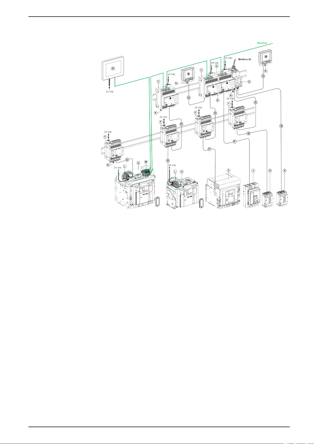
Communication Architecture
A FDM128 Ethernet display for eight devices
B FDM121 front display module for one circuit breaker
C IFE Ethernet interface for one circuit breaker
D IFE Ethernet switchboard server
E IFM Modbus-SL interface for one circuit breaker
F IO input/output application module for one circuit breaker
G MasterPact MTZ1 or MTZ2/MTZ3 drawout circuit breaker
H MasterPact MTZ1 or MTZ2/MTZ3 fixed circuit breaker
I MasterPact NT/NW circuit breaker
J ComPact NS/PowerPact M-,P,- and R-frame circuit breaker
K ComPact NSX/PowerPact H-, J-, and L-frame circuit breaker
L ULP port module
M EIFE Embedded Ethernet Interface for one MasterPact MTZ drawout circuit breaker
N ULP line termination
O RJ45 male/male ULP cord
P Circuit breaker BCM ULP cord
Q NSX cord
Remote Controller
A remote controller is a device that is able to communicate with an IMU using a
communication interface, such as the IFE server. For example, FDM128 Ethernet
display for eight devices, supervisor, PLC, BMS, SCADA system, and so on, are
remote controllers.
DOCA0084EN-09 13
Page 14

Ethernet Switchboard Server Intelligent Modular Unit
For the description of Modbus registers and commands, refer to the Modbus
Communication Guides.
14 DOCA0084EN-09
Page 15
Hardware Description Ethernet Switchboard Server
Hardware Description
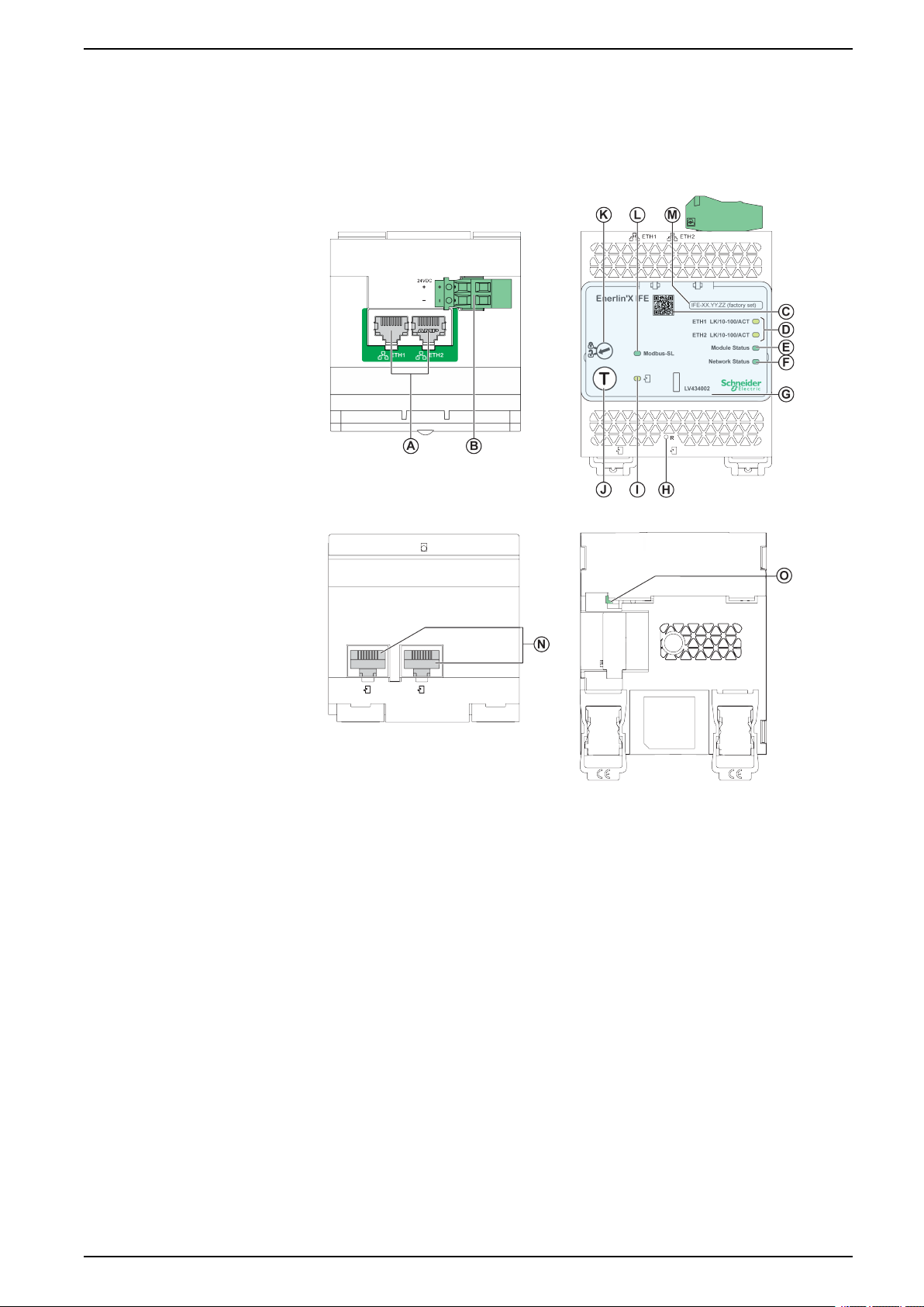
Description
A Ethernet 1 and Ethernet 2 RJ45 communication ports
B 24 Vdc power supply terminal block
C QR code to product information
D Ethernet communication LEDs
E Module status LED
F Network status LED
G Sealable transparent cover
H Reset button
I ULP status LED
J Test button (accessible even with closed cover)
K Locking pad
L Modbus traffic status LED (IFE server only)
M Device name label
N Two RJ45 ULP ports
0 Grounding connection
DOCA0084EN-09 15
Page 16
Ethernet Switchboard Server Hardware Description
For information on installation, consult the instruction sheet available on the
Schneider Electric website: QGH13473.
Mounting
The IFE server mounts on a DIN rail. The stacking accessory enables the
connection of several IFM interfaces to an IFE server without additional wiring.
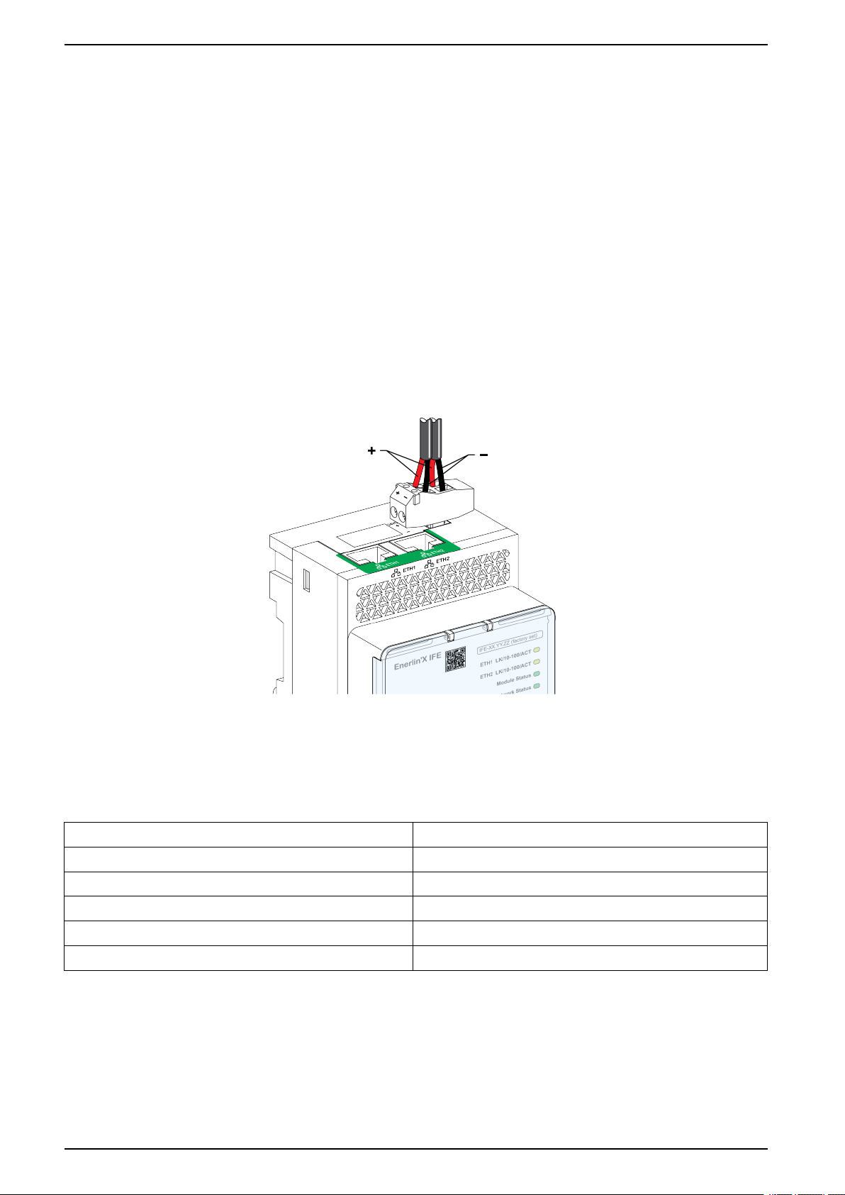
24 Vdc Power Supply
The IFE server must always be supplied with 24 Vdc. The power to the IFM
interfaces stacked to an IFE server are supplied by the IFE server and it is not
necessary to supply power to them separately.
It is recommended to use an UL listed and recognized limited voltage/limited
current or a class 2 power supply with a 24 Vdc, 3 A maximum.
NOTE: For 24 Vdc power supply connection, use copper conductors only.
Ethernet Communication LEDs
The Ethernet communication dual color LEDs, indicate the status of the Ethernet
ports ETH1 and ETH2.
LED Indication Status Description
OFF No power or no link
Steady yellow 10 Mbps, link established, and no activity
Blinking yellow 10 Mbps, ongoing activity
Steady green 100 Mbps, link established, and no activity
Blinking green 100 Mbps, ongoing activity
16 DOCA0084EN-09
Page 17

Hardware Description Ethernet Switchboard Server
Module Status LED
The module status dual color LED, indicates the IFE server status.
LED Indication Status Description Action
OFF No power None
Steady green IFE server operational None
Blinking green (250 ms ON, 250 ms OFF) Hidden control webpage available None
Blinking green (500 ms ON, 500 ms OFF) IFE server firmware corrupted Contact your local Schneider Electric service
Blinking red (500 ms ON, 500 ms OFF) IFE server in degraded mode Replace ULP module at the next
Steady red IFE server out of service None
Blinking green/red (1 s green, 1 s red) Firmware update in progress None
Blinking green/red (250 ms green, 250 ms red) Self-test in progress None
team for support.
maintenance operation.
Network Status LED
The network status dual color LED, indicates the Ethernet network status.
LED Indication Status Description
OFF No power or no IP address
Steady green Valid IP address
Steady red Duplicated IP address
Blinking green/red (250 ms green, 250 ms red) Self-test in progress
Steady amber Error in IP configuration
Modbus Serial Line Traffic LED
The Modbus serial line traffic yellow LED, indicates that the traffic is being
transmitted or received over the Modbus serial line network through the IFE
server.
The LED is ON during the transmission and reception of the messages. The LED
is OFF otherwise.
Modbus Address
The IFE server accepts the Modbus address of the IMU to which it is connected.
The Modbus address is 255 and cannot be changed.
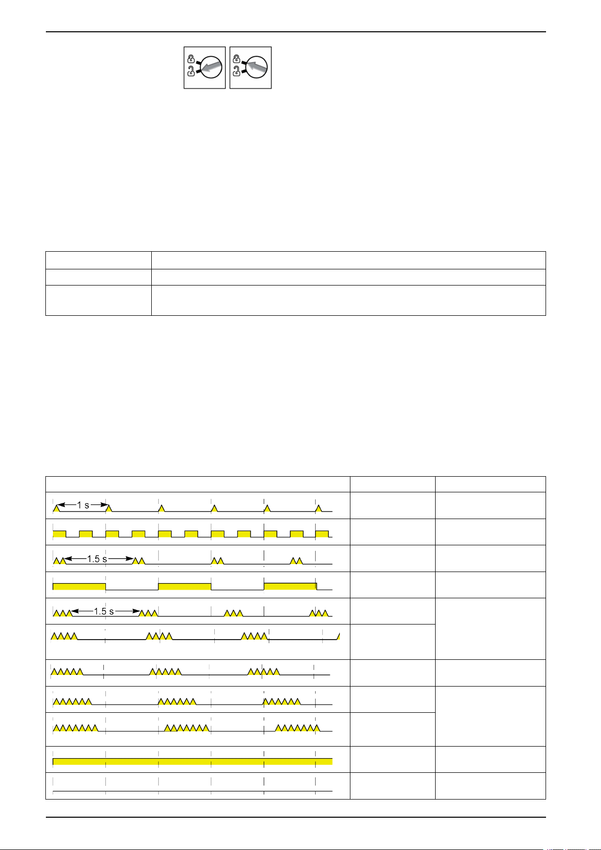
Locking Pad
The locking pad on the front panel of the IFE server enables or disables the ability
to send the remote control commands over the Ethernet network to the IFE server,
and to the other modules of the IMU
DOCA0084EN-09 17
Page 18
Ethernet Switchboard Server Hardware Description
• If the arrow points to the open padlock (factory setting), remote control
commands are enabled.
• If the arrow points to the closed padlock, remote control commands are
disabled.
The only remote control command that is enabled even if the arrow points to
the closed padlock, is the set absolute time command.
Test Button
The test button has two functions, according to the duration of the button pressed.
Time Range Function
1–5 s Tests the connection between all the ULP modules for 15 s.
10–15 s Activates the hidden configuration mode.
NOTE: The hidden configuration is not activated if the button is pressed for more than 15 s.
Reset Button
When the reset button is pressed for 1–5 s, it forces the IP acquisition mode to the
factory default setting (DHCP).
ULP Status LED
The yellow ULP status LED describes the mode of the ULP module.
ULP LED Mode Action
Nominal None
Conflict Remove extra ULP module
Degraded Replace ULP module at the
Test None
Non-critical firmware
discrepancy
Non-critical
hardware
discrepancy
next maintenance operation
Use EcoStruxure Power
Commission software to
check the firmware and
hardware compatibility and
follow the recommended
actions
Configuration
discrepancy
Critical firmware
discrepancy
Critical hardware
discrepancy
Stop Replace ULP module
Power OFF Check power supply
Install missing features
Use EcoStruxure Power
Commission software to
check the firmware and
hardware compatibility and
follow the recommended
actions
18 DOCA0084EN-09
Page 19

EcoStruxure Power Commission Software Ethernet Switchboard Server
EcoStruxure Power Commission Software
Overview
EcoStruxure Power CommissionTMis the new name of Ecoreach software.
EcoStruxure Power Commission software helps you to manage a project as part
of testing, commissioning, and maintenance phases of the project life cycle. The
innovative features in it provide simple ways to configure, test, and commission
the smart electrical devices.
EcoStruxure Power Commission software automatically discovers the smart
devices and allows you to add the devices for an easy configuration. You can
generate comprehensive reports as part of Factory Acceptance Test and Site
Acceptance Test to replace your heavy manual work. Additionally, when the
panels are under operation, any change of settings made can be easily identified
by a yellow highlighter. This indicates the difference between the project and
device values, and hence provides a system consistency during the operation and
maintenance phase.
EcoStruxure Power Commission software enables the configuration of the
following circuit breakers, modules, and accessories:
Circuit breaker ranges Modules Accessories
MasterPact MTZ circuit breakers • MicroLogic control units
• Communication interface modules: IFM interface,
IFE interface, IFE server, and EIFE interface
• ULP modules: IO module
• MasterPact NT/NW circuit breakers
• ComPact NS circuit breakers
• PowerPact P- and R-frame circuit
breakers
• ComPact NSX circuit breakers
• PowerPact H-, J- and L-frame circuit
breakers
(1) For FDM121 display, only the firmware and language download are supported.
• MicroLogic trip units
• Communication interface modules: BCM module,
CCM module, BCM ULP module, IFM interface, IFE
interface, IFE server
• ULP modules: IO module, FDM121 display
• MicroLogic trip units
• Communication interface modules: BSCM module,
IFM interface, IFE interface, IFE server
• ULP modules: IO module, FDM121 display
(1)
(1)
M2C output module
M2C and M6C output
modules
SDTAM and SDx output
modules
For more information, refer to the EcoStruxure Power Commission Online Help.
EcoStruxure Power Commission software is available at www.se.com
DOCA0084EN-09 19
Page 20

Ethernet Switchboard Server EcoStruxure Power Commission Software
Key Features
EcoStruxure Power Commission software performs the following actions for the
supported devices and modules:
• Create projects by device discovery
• Save the project in the EcoStruxure Power Commission cloud for reference
• Upload settings to the device and download settings from the device
• Compare the settings between the project and the device
• Perform control actions in a secured way
• Generate and print the device settings report
• Perform a communication wiring test on the entire project and generate and
print test report
• View the communication architecture between the devices in a graphical
representation
• View the measurements, logs, and maintenance information
• Export Waveform Capture on Trip Event (WFC)
• View the status of device and IO module
• View the alarm details
• Buy, install, remove, or retrieve the Digital Modules
• Check the system firmware compatibility status
• Update to the latest device firmware
• Perform force trip and automatic trip curve tests
20 DOCA0084EN-09
Page 21
Schematics with MasterPact MTZ Circuit Breakers Ethernet Switchboard Server
Schematics with MasterPact MTZ Circuit Breakers
Description
The IFE server is connected to the MasterPact MTZ circuit breaker through its
ULP port module.
For more information, refer to the ULP System User Guides .
ULP Connection
NOTICE
HAZARD OF EQUIPMENT DAMAGE
• Never connect an Ethernet device to an RJ45 ULP port.
• The RJ45 ULP ports of IFE server are for ULP modules only.
• Any other use can damage the IFE server or the device connected to the IFE
server.
• To check if an ULP module is compatible with the RJ45 ULP ports of IFE
server, refer to the ULP System User Guides.
Failure to follow these instructions can result in equipment damage.
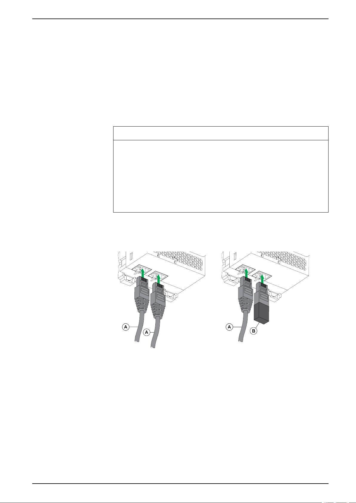
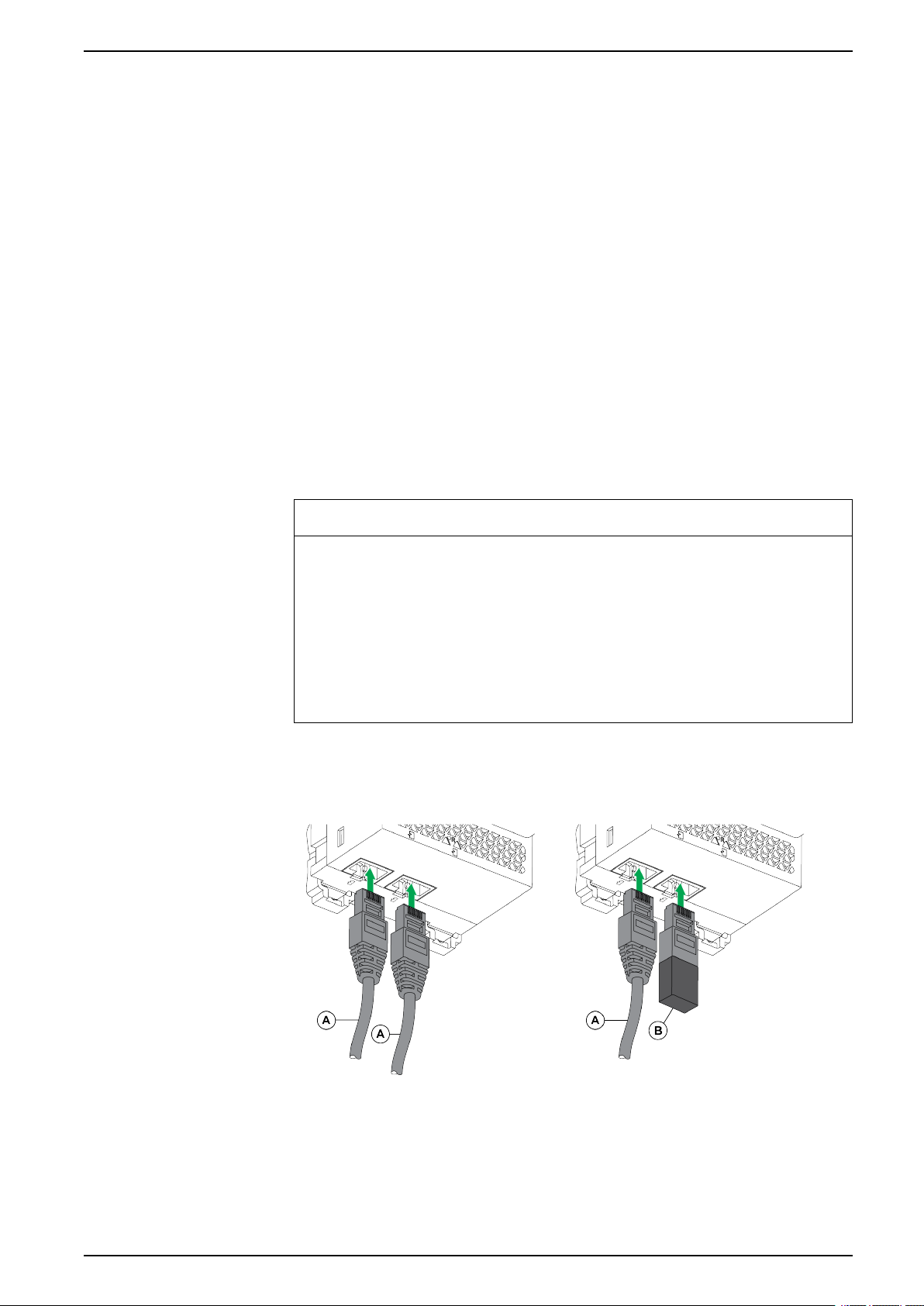
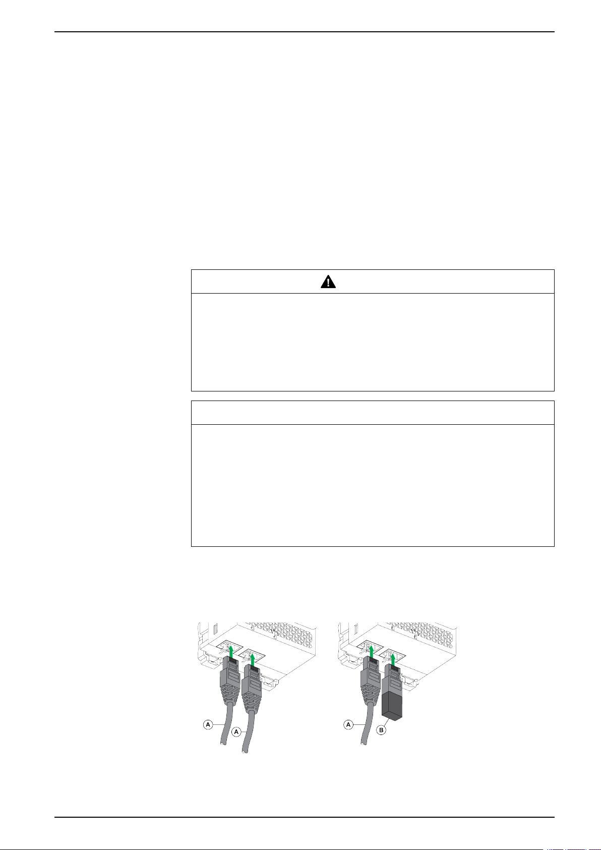
All the connection configurations require the RJ45 male/male ULP cord.
When the second RJ45 ULP port is not used, it must be closed with an ULP line
termination.
A RJ45 male/male ULP cord
B ULP line termination
DOCA0084EN-09 21
Page 22
Ethernet Switchboard Server Schematics with MasterPact MTZ Circuit Breakers
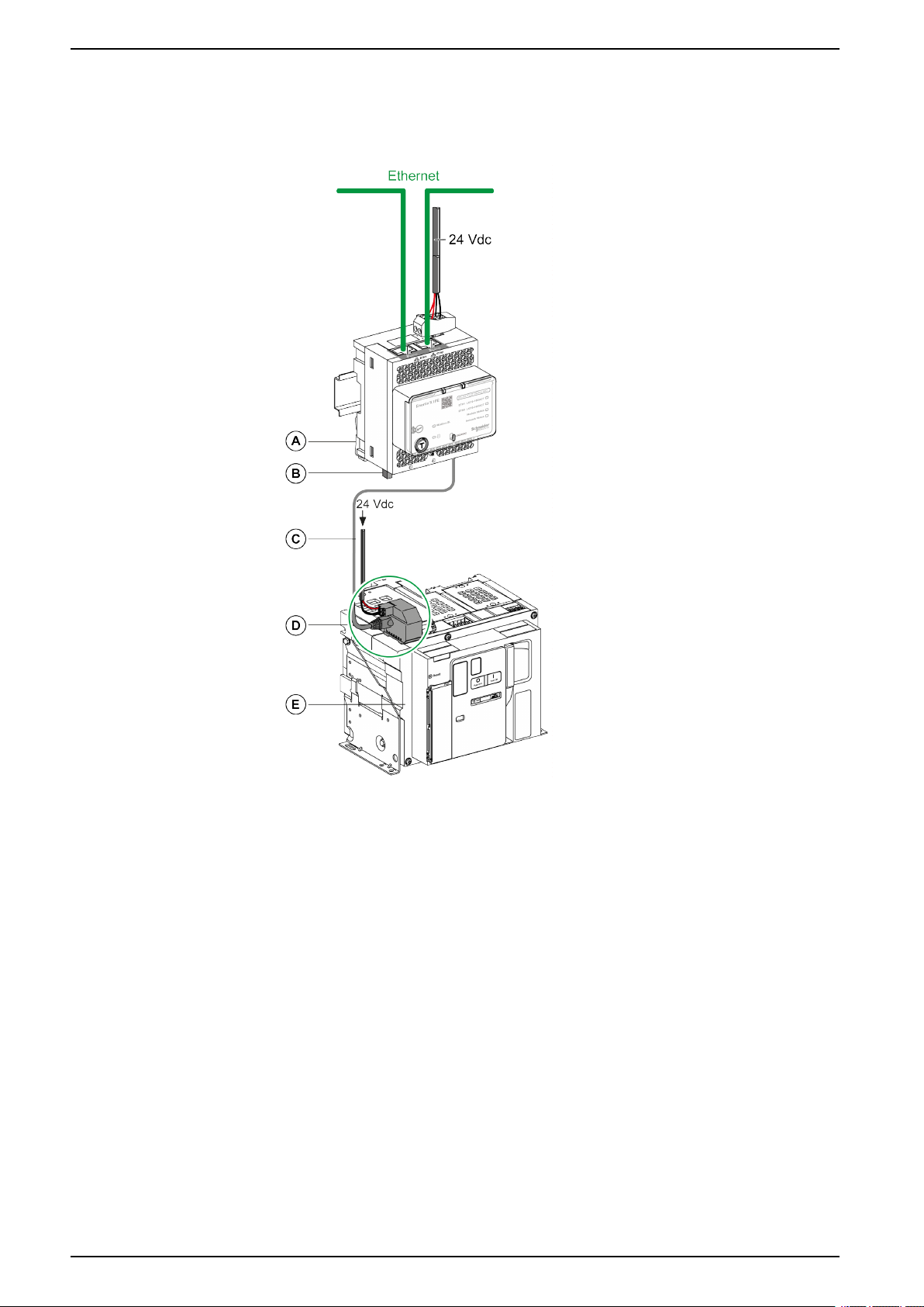
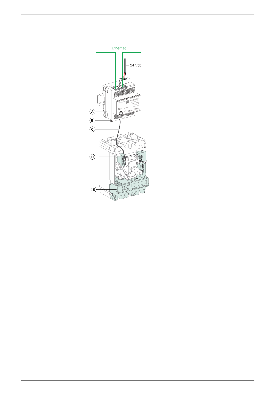
Connection of the IFE Server to a MasterPact MTZ Circuit Breaker
Connect the IFE server to the ULP port module on a MasterPact MTZ circuit
breaker by using the ULP cord.
A IFE Ethernet switchboard server
B ULP line termination
C RJ45 male/male ULP cord
D ULP port module
E MasterPact MTZ fixed circuit breaker
22 DOCA0084EN-09
Page 23
Schematics with MasterPact NT/NW and ComPact NS Circuit
Breakers Ethernet Switchboard Server
Schematics with MasterPact NT/NW and ComPact NS Circuit Breakers
Description
Depending on the type of circuit breaker used, connect the IFE server to the circuit
breaker using one of the following configurations:
• Connection of the IFE server to a fixed manually-operated ComPact NS
circuit breaker with a BCM ULP module.
• Connection of the IFE server to a fixed electrically-operated MasterPact NT/
NW or ComPact NS 630b-1600 circuit breaker with a BCM ULP module.
• Connection of the IFE server to a drawout MasterPact NT/NW or ComPact
NS 630b-1600 circuit breaker with a BCM ULP module and its respective IO
module.
For more information, refer to the ULP System User Guide.
ULP Connection
NOTICE
HAZARD OF EQUIPMENT DAMAGE
• Never connect an Ethernet device to a RJ45 ULP port.
• The RJ45 ULP ports of IFE server are for ULP modules only.
• Any other use can damage the IFE server or the device connected to the IFE
server.
• To check if a ULP module is compatible with the RJ45 ULP ports of IFE
server, refer to the ULP System User Guide.
Failure to follow these instructions can result in equipment damage.
All connection configurations require the BCM ULP cord.
When the second RJ45 ULP port is not used, it must be closed with a ULP line
termination.
A Circuit breaker BCM ULP cord or RJ45 male/male ULP cord
B ULP line termination
DOCA0084EN-09 23
Page 24
Ethernet Switchboard Server
Schematics with MasterPact NT/NW and ComPact NS Circuit
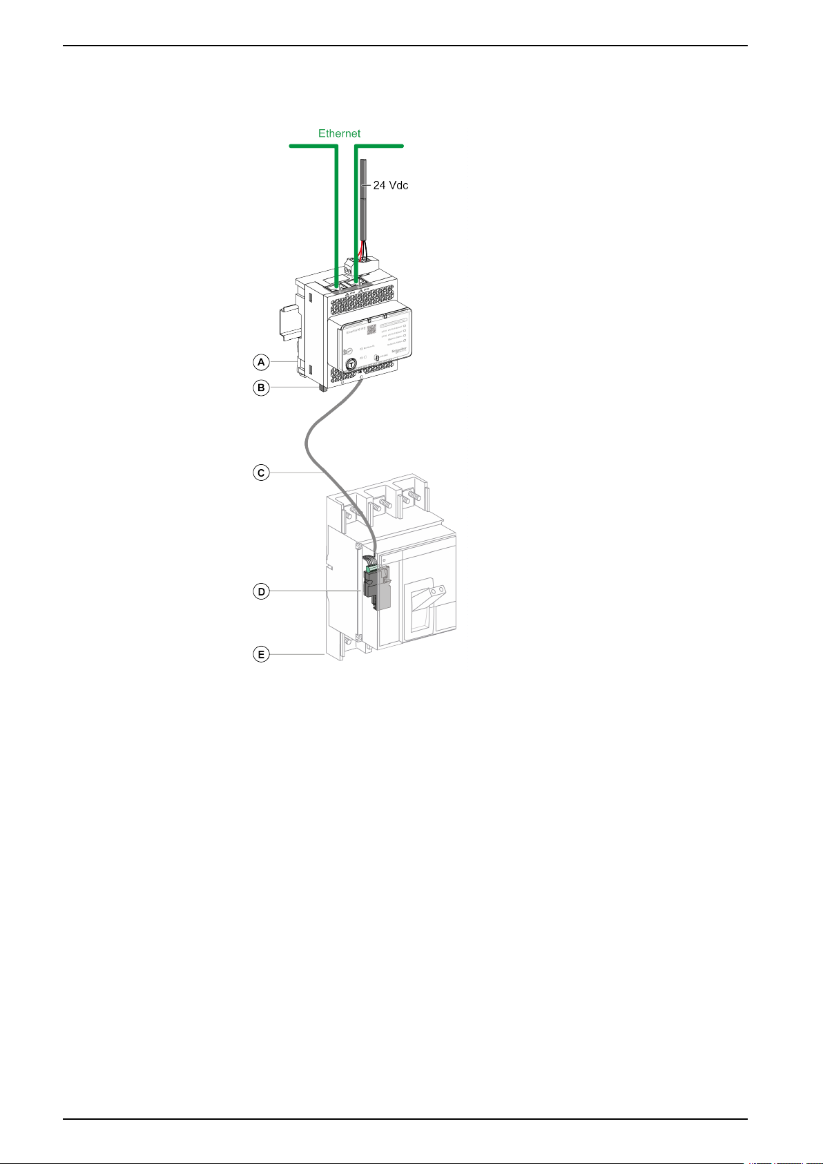
Connection of the IFE Server to a Fixed Manually-Operated
ComPact NS Circuit Breaker
Breakers
A IFE Ethernet switchboard server
B ULP line termination
C Circuit breaker BCM ULP cord
D BCM ULP circuit breaker communication module
E Fixed manually-operated ComPact NS circuit breaker
24 DOCA0084EN-09
Page 25
Schematics with MasterPact NT/NW and ComPact NS Circuit
Breakers Ethernet Switchboard Server
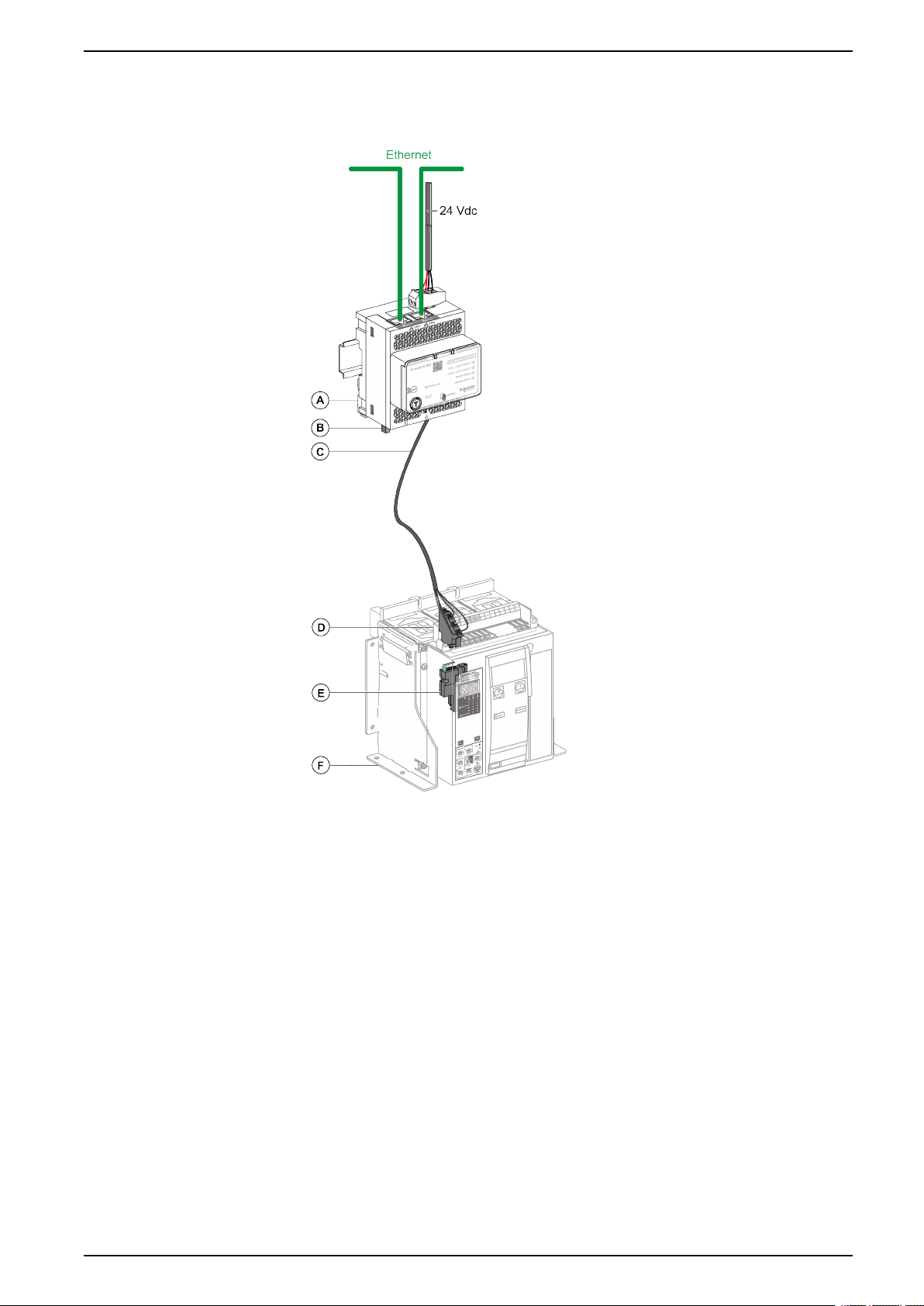
Connection of the IFE Server to a Fixed Electrically-Operated
MasterPact NT/NW or ComPact NS 630b-1600 Circuit Breaker
A IFE Ethernet switchboard server
B ULP line termination
C Circuit breaker BCM ULP cord
D Fixed terminal block
E BCM ULP circuit breaker communication module
F Fixed electrically-operated circuit breaker
DOCA0084EN-09 25
Page 26
Ethernet Switchboard Server
Schematics with MasterPact NT/NW and ComPact NS Circuit
Breakers
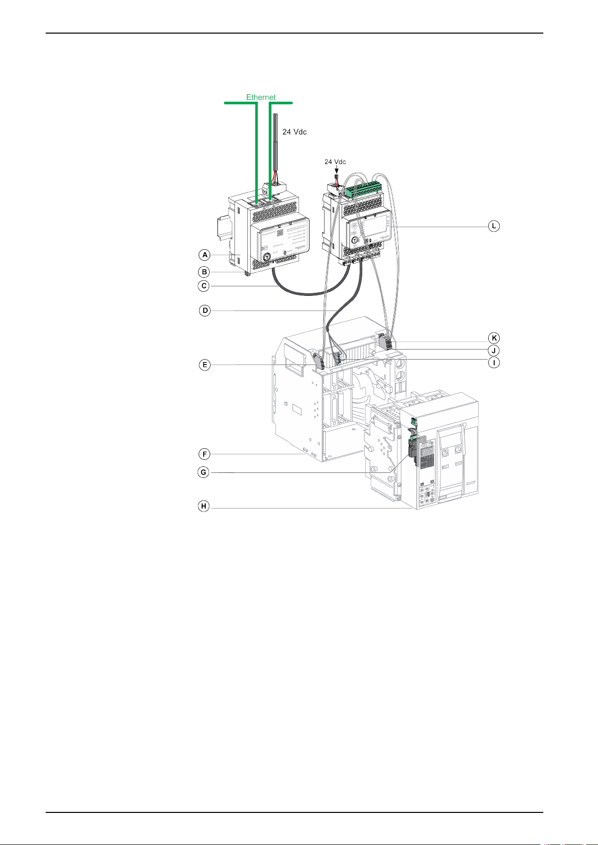
Connection of the IFE Server to a Drawout MasterPact NT/NW or
ComPact NS 630b-1600 Circuit Breaker
A IFE Ethernet switchboard server
B ULP line termination
C RJ45 male/male ULP cord
D Circuit breaker BCM ULP cord
E Circuit breaker disconnected position contact (CD)
F Circuit breaker cradle
G BCM ULP circuit breaker communication module
H Drawout circuit breaker
I Drawout terminal block
J Circuit breaker connected position contact (CE)
K Circuit breaker test position contact (CT)
L IO input/output application module for one circuit breaker
26 DOCA0084EN-09
Page 27
Schematics with ComPact NSX Circuit Breakers Ethernet Switchboard Server
Schematics with ComPact NSX Circuit Breakers
General Description
Depending on the configuration of the ComPact NSX circuit breaker, connect the
IFE server to the circuit breaker using one of the following configurations:
• Connection of the IFE server to the MicroLogic trip unit
• Connection of the IFE server to the BSCM module
• Connection of the IFE server to the BSCM module and to the MicroLogic trip
unit
For more information, refer to the ULP System User Guide.
ULP Connection
WARNING
HAZARD OF ELECTRIC SHOCK
For system voltage greater than 480 Vac:
• Use the insulated NSX cord LV434204.
• Do not use NSX cords LV434200, LV434201, and LV434202.
Failure to follow these instructions can result in death, serious injury, or
equipment damage.
NOTICE
HAZARD OF EQUIPMENT DAMAGE
• Never connect an Ethernet device to an RJ45 ULP port.
• The RJ45 ULP ports of IFE server are for ULP modules only.
• Any other use can damage the IFE server or the device connected to the IFE
server.
• To check if an ULP module is compatible with the RJ45 ULP ports of IFE
server, refer to the ULP System User Guide.
Failure to follow these instructions can result in equipment damage.
All connection configurations require the NSX cord. The insulated NSX cord is
mandatory for system voltages greater than 480 Vac.
When the second RJ45 ULP port is not used, it must be closed with an ULP line
termination.
A NSX cord or RJ45 male/male ULP cord
B ULP line termination
DOCA0084EN-09 27
Page 28
Ethernet Switchboard Server Schematics with ComPact NSX Circuit Breakers
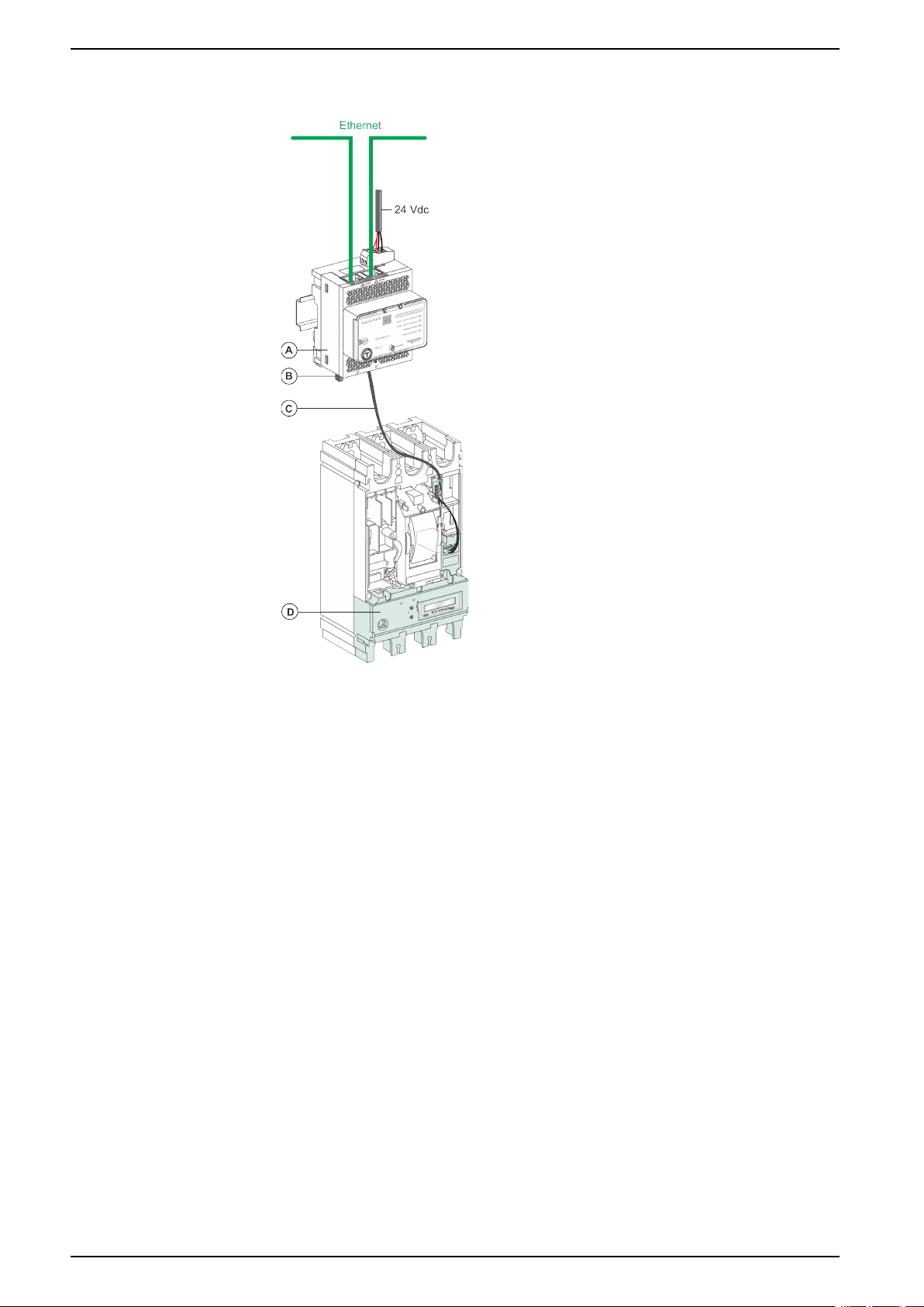
Connection of the IFE Server to the MicroLogic Trip Unit
A IFE Ethernet switchboard server
B ULP line termination
C NSX cord
D MicroLogic trip unit
28 DOCA0084EN-09
Page 29
Schematics with ComPact NSX Circuit Breakers Ethernet Switchboard Server
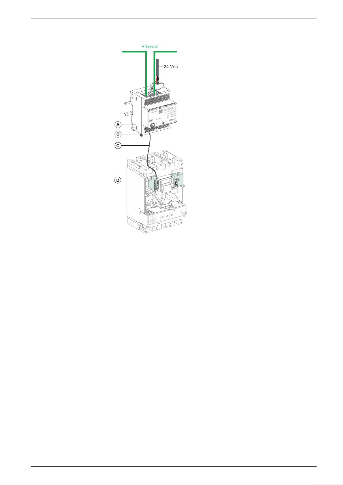
Connection of the IFE Server to the BSCM Module
A IFE Ethernet switchboard server
B ULP line termination
C NSX cord
D BSCM breaker status control module
DOCA0084EN-09 29
Page 30
Ethernet Switchboard Server Schematics with ComPact NSX Circuit Breakers
Connection of the IFE Server to the BSCM Module and to the
MicroLogic Trip Unit
A IFE Ethernet switchboard server
B ULP line termination
C NSX cord
D BSCM breaker status control module
E MicroLogic trip unit
30 DOCA0084EN-09
Page 31

Schematics with ComPact NSX Circuit Breakers Ethernet Switchboard Server
Connection of the IFE Server to a Circuit Breaker for System
Voltage Greater Than 480 Vac
A IFE Ethernet switchboard server
B ULP line termination
C RJ45 male/male ULP cord
D Insulated ULP module for system voltage greater than 480 Vac
E Insulated ULP cord for system voltage greater than 480 Vac
F ComPact NSX internal connection
DOCA0084EN-09 31
Page 32

Ethernet Switchboard Server Technical Characteristics
Technical Characteristics
Environmental Characteristics
Characteristics Value
Conforming to standards • IACS E10
• EN 61326-1
• CSA C22.2
• IEC/UL 61010-2-201
• IEC61000-6-2 Ed.2
Certification cULus, CE, EAC, and FCC marking
Ambient temperature Storage -40 °C to +85 °C (-40 °F to +185 °F)
Operation -25 °C to +70 °C (-13 °F to +158 °F)
Protective treatment ULV0, conforming to IEC/EN 60068-2-30
Pollution Level 3
Mechanical Characteristics
Characteristics Value
Shock resistance Conforming to IEC 60068-2-27
15 g/11 ms, 1/2 sinusoidal
Resistance to sinusoidal vibrations Conforming to IEC/EN 60068-2-6
Electrical Characteristics
Characteristics Value
Power supply 24 Vdc, -20%/+10% (19.2–26.4 Vdc)
Consumption Typical 24 Vdc, 120 mA at 20 °C (68 °F)
Maximum with server 19.2 Vdc, 140 mA at 60 °C (140 °F)
Physical Characteristics
Characteristics Value
Dimensions 72 x 105 x 71 mm (2.83 x 4.13 x 2.79 in)
Mounting DIN rail
Weight 187 g (0.41 lb)
Degree of protection of the installed module • On the front panel (wall-mounted enclosure): IP4x
• Connectors: IP2x
• Other parts: IP3x
Connections Screw type terminal blocks
32 DOCA0084EN-09
Page 33

Technical Characteristics Ethernet Switchboard Server
24 Vdc Power Supply Characteristics
It is recommended to use an UL listed/UL recognized limited voltage/limited
current or a class 2 power supply with a 24 Vdc, 3 A maximum.
NOTE: For 24 Vdc power supply connection, use copper conductors only.
For more information, refer to the ULP System User Guide.
Characteristics Value
Power supply type Regulated switch type
Rated power 72 W
Input voltage 100–120 Vac for single phase
200–500 Vac phase-to-phase
PFC filter With IEC 61000-3-2
Output voltage 24 Vdc
Power supply output current 3 A
DOCA0084EN-09 33
Page 34

Ethernet Switchboard Server Firmware Update
Firmware Update
Description
Use the latest version of EcoStruxure Power Commission software for all firmware
updates.
The latest version of IFE firmware and IFE webpages are updated in a single
operation through EcoStruxure Power Commission software.
For more information on IFE firmware versions, refer to Enerlin'X IFE Server
Firmware Release Note.
WARNING
LOSS OF DATA
Backup the data log files before updating the firmware.
The data log entries of the IFE server may be lost when the IFE firmware is
updated.
Failure to follow these instructions can result in death, serious injury, or
equipment damage.
After updating the firmware of one device in the IMU, use the latest version of
EcoStruxure Power Commission software to check the firmware compatibility
between the IMU devices. The Firmware Update table helps you to diagnose and
identify all discrepancy issues between the IMU devices. This table also provides
the recommended actions relevant to the detected discrepancies.
Checking the Firmware Version
You can find the firmware version of the devices in the IMU by using:
• EcoStruxure Power Commission software, refer to the EcoStruxure Power
Commission Online Help.
• IFE webpages, see the procedure below.
Step Action Result
1 Open the web browser and log in to the IFE webpage. Opens the IFE home page.
2 Locate the firmware version on Device Information page
on the Diagnostics menu , page 96.
NOTE: If you have updated the firmware recently,
press F5 to refresh the webpage and update the
displayed firmware number.
Determines the firmware version of the IFE server.
Updating the Firmware and Webpages, Using EcoStruxure Power
Commission Software
For more information, refer to the EcoStruxure Power Commission Online Help.
The EcoStruxure Power Commission software is available at www.se.com.
34 DOCA0084EN-09
Page 35

Schneider Electric Green Premium™Ecolabel Ethernet Switchboard Server
Schneider Electric Green Premium™Ecolabel
Description
Green Premium by Schneider Electric is a label that allows you to develop and
promote an environmental policy while preserving your business efficiency. This
ecolabel is compliant with up-to-date environmental regulations.
Accessing Green Premium
Green Premium data on labeled products can be accessed online through any of
the following ways:
• By navigating to the Green Premium page on the Schneider Electric website.
• By flashing the QR code displayed in the following image:
Checking Products Through the Schneider Electric Website
To check the environmental criteria of a product using a PC or smartphone, follow
these steps:
Step Action
1
2 Click Find Green Premium Products to open the search tool webpage.
3 Fill in the fields:
4 To search for several products simultaneously, click the Add product button, and then fill in the fields.
5
From www.se.com, select Support
• Enter the commercial reference or product range of the product to search for.
• Optional: Enter the manufacturing date code of the product with format YYWW. By default, this field is filled with the
date of the search.
Click Check product(s) to generate a report of the environmental criteria available for the products with the entered
commercial references.
> Additional Links > Green Premium Eco Label.
DOCA0084EN-09 35
Page 36

Ethernet Switchboard Server Schneider Electric Green Premium™Ecolabel
Environmental Criteria
The Green Premium ecolabel provides documentation on the following criteria
about the environmental impact of the products:
• RoHs: European Union Restriction of Hazardous Substances (RoHS)
directive.
• REACh: European Union Registration, Evaluation, Authorization, and
Restriction of Chemicals regulation.
• PEP: Product Environmental Profile.
• EoLI: End of Life Instructions.
RoHs
Schneider Electric products are subject to RoHS requirements at a worldwide
level, even for the many products that are not required to comply with the terms of
the regulation. Compliance certificates are available for products that fulfill the
criteria of this European initiative, which aims to eliminate hazardous substances.
REACh
PEP
EoLI
Schneider Electric applies the strict REACh regulation on its products at a
worldwide level, and discloses extensive information concerning the presence of
SVHC (Substances of Very High Concern) in all of these products.
Schneider Electric publishes complete set of environmental data, including carbon
footprint and energy consumption data for each of the life cycle phases on all of its
products, in compliance with the ISO 14025 PEP ecopassport program. PEP is
especially useful for monitoring, controlling, saving energy, and/or reducing
carbon emissions.
These instructions provide:
• Recyclability rates for Schneider Electric products.
• Guidance to mitigate personnel hazards during the dismantling of products
and before recycling operations.
• Part identification for recycling or for selective treatment, to mitigate
environmental hazards/incompatibility with standard recycling processes.
36 DOCA0084EN-09
Page 37

IFE Server Webpages
What’s in This Part
IFE Interface.................................................................................................. 38
Configuration & Settings Webpages ................................................................ 46
Monitoring Webpges.......................................................................................80
Control Webpages .........................................................................................87
Diagnostics Webpages...................................................................................92
Maintenance Webpages ............................................................................... 101
Ethernet Switchboard Server
DOCA0084EN-09 37
Page 38

Ethernet Switchboard Server IFE Interface
IFE Interface
What’s in This Chapter
Access to IFE Webpages............................................................................... 39
User Interface Layout .................................................................................... 42
Webpage Description .................................................................................... 44
38 DOCA0084EN-09
Page 39

IFE Interface Ethernet Switchboard Server
Access to IFE Webpages
Supported Web Browsers
Browser Version with WindowsXPVersion with Windows Vista Version with Windows 7 and
Internet Explorer IE 9.0 IE 9.0 IE 10.0, IE11.0
Firefox 15.0 20.0 20.0, 45.0
Chrome (recommended) 24.0 and later 24.0 and later 24.0 and later
later
First Access to the IFE Webpages
The IFE name must be configured during the first access to the IFE webpages.
WARNING
POTENTIAL COMPROMISE OF SYSTEM AVAILABILITY, INTEGRITY, AND
CONFIDENTIALITY
Change default passwords at first use to help prevent unauthorized access to
device settings, controls, and information.
Failure to follow these instructions can result in death, serious injury, or
equipment damage.
The procedure to access the IFE webpages for the first time depends on the
operating system of the PC:
• Windows Vista, Windows 7 and later, or newer operating systems
• Windows XP or older operating systems
NOTE: After updating the IFE server, delete the browser cache before
accessing the webpages for the first time.
First Access Through PC with Windows Vista or Windows 7 and Later
Step Action
1 Disconnect the PC from the local area network (LAN) and switch off Wi-Fi.
2 Connect an Ethernet cable from the PC to the IFE server or to the Ethernet switch inside the panel.
3 Open Windows Explorer.
4 Click Network and the IFE-XXYYZZ appears in the list of devices.
NOTE: If the IFE name is not displayed in the list of devices in Windows Explorer, check if the PC and the IFE
server are not connected through the router.
5 Double-click the selected IFE-XXYYZZ, the login page automatically opens in the browser.
6 Enter Administrator as the user name and Gateway as the default password, the home page automatically opens in
7
8 To locate the IFE-XXYYZZ, select the Configuration & Settings menu, go to General submenu, click Device Physical
9 To name the IFE-XXYYZZ, select the Configuration & Settings menu, go to Device Configuration submenu, click
10 Write the IFE name on a blank device name label and stick it on the existing one.
the browser.
NOTE: The user name and password are case-sensitive. The Administrator user name cannot be changed as it
is default user name for administrator role.
To change the default password, select the Configuration and settings menu, go to Other Configuration submenu,
click User Accounts and enter new password for Administrator user name.
Location, and click Blink ON. The ULP LED of the selected IFE-XXYYZZ blinks for 15 seconds (test mode).
Device List and then click Name. Click IFE-XXYYZZ to set the IFE name.
DOCA0084EN-09 39
Page 40

Ethernet Switchboard Server IFE Interface
NOTE:
• XXYYZZ is the last 3 bytes of the MAC address in hexadecimal format.
• Check the firewall settings if DPWS is not enabled.
First Access Through PC with Windows XP
Step Action
1 Disconnect the PC from the local area network (LAN) and switch off Wi-Fi.
2 Connect an Ethernet cable from the PC to the IFE server.
3 Start the web browser, page 39.
NOTE: The PC automatically uses the default IP address 169.254.#.# (#=0–255) and the default subnet mask
255.255.0.0.
4 In the address text box, enter 169.254.YY.ZZ, where YY and ZZ are the last 2 bytes of the IFE server MAC address
5 Press Enter, the login page automatically opens in the browser.
(to be found on the IFE server side label), then press Enter: the home page opens in the browser.
Example: For an IFE with MAC address 00-B0-D0-86-BB-F7 or 0-176-208-134-187-247 in decimal, enter
169.254.187.247 in the address text box.
6 Enter Administrator as the user name and Gateway as the default password. The homepage automatically opens
7
8 To locate the -XXYYZZ, select the Configuration & Settings menu, go to General submenu, click Device Physical
9 To name the -XXYYZZ, select the Configuration & Settings menu, go to Device Configuration submenu, click
10 Write the IFE name on a blank device name label and stick it on the existing one.
in the browser.
NOTE: The user name and password are case-sensitive. The Administrator user name cannot be changed as
it is default user name for administrator role.
To change the default password, select the Configuration and settings menu, go to Other Configuration submenu,
click User Accounts and enter new password for Administrator user name.
Location, go to Device Physical Location, and click Blink ON. The ULP LED of the selected -XXYYZZ blinks for 15
seconds.
Device List and then click Name to set the IFE name.
NOTE: XXYYZZ is the last 3 bytes of the MAC address in hexadecimal format.
Access to Webpages
Follow the Network Discovery, Name Browsing, and IP Address Browsing process
to access the webpages.
The webpage access depends on the IT infrastructure.
40 DOCA0084EN-09
Page 41

IFE Interface Ethernet Switchboard Server
Network Discovery
Follow the below procedure to access the IFE webpages once the IFE name has
been configured.
Step Action
1 Connect the IFE server or the Ethernet switch inside the panel to the local area network (LAN).
2 Connect the PC to the local area network (LAN).
3 Open Windows Explorer.
4 Click Network, the IFE name is displayed in the list of devices.
NOTE: If the IFE name is not displayed in the list of devices in Windows Explorer, check if the PC and the IFE server
are not connected through the router.
5
Double-click the IFE name which is written on the device label located on the front face of the selected IFE server, the login
page automatically opens in the browser.
Name Browsing
DNS server is mandatory.
Step Action
1 Connect the IFE server or the Ethernet switch inside the panel to the local area network (LAN).
2 Connect the PC to the local area network (LAN).
3 Start the web browser, page 39.
4 In the address text box, enter the IFE name which is written on the device label located on the front face of the selected IFE
5 Press Enter, the login page automatically opens in the browser.
server.
NOTE: If the IFE server does not appear in the list of devices in Windows Explorer, check if the PC and the IFE server
are not connected through the router.
NOTE: The IFE IP address is mapped to the device label in the DNS server.
IP Address Browsing
IP static configuration has to be set.
Step Action
1 Connect the IFE server or the Ethernet switch inside the panel to the local area network (LAN).
2 Connect the PC to the local area network (LAN).
3 Start the web browser, page 39.
4 In the address text box, enter IP address given by the IT administrator.
5 Press Enter, the login page automatically opens in the browser.
NOTE: If the login page in the web browser does not open or does not display correctly, check if Internet Explorer
\Tools\Compatibility View Settings\Display Intranet sites in Compatibility View in Internet Explorer is checked.
DOCA0084EN-09 41
Page 42

Ethernet Switchboard Server IFE Interface
User Interface Layout
Overview
This graphic shows the IFE user interface layout.
A Banner
B Menu tabs
C Subtabs
D Action button
E Display zone
Banner
The banner displays the following information at the top of all the pages.
Generic Information Description
Date and time Current date and time in the format yyyy-mm-dd hh-mm-sec
User name checked Name of the user who has logged in
Logout To log out the IFE session, click Logout or close your browser. It is recommended to log
out from the IFE session when it is not in use.
Main Tabs
The main tabs are:
• Monitoring
• Control
• Diagnostics
• Maintenance
• Configuration & Settings
Subtabs
The subtabs display the submenus under the selected main tab.
42 DOCA0084EN-09
Page 43

IFE Interface Ethernet Switchboard Server
Action Buttons
The action buttons correspond to the selected tab and it varies.
The following table describes the interface buttons:
Button Action
Apply Applies the changes.
Cancel Cancels the modifications to return to the last saved settings.
Display Zone
The display zone shows the selected subtab in detail with all the related fields.
DOCA0084EN-09 43
Page 44

Ethernet Switchboard Server IFE Interface
Webpage Description
Monitoring Webpage
Monitoring Submenu Webpage Description
Real Time Data Single Device Pages, page
81
Summary Device Pages,
page 81
Trending, page 82 The trending page view provides real-time graphic and table trending
Device Logging Single Device Pages, page
83
Summary Device Pages ,
page 86
The single device pages provide basic readings of the selected
devices.
The summary device pages provide summaries of one or more
selected devices.
of common topics across multiple devices.
The single device pages provide the graphic and table trending logs of
user-selectable quantities for selected devices.
The summary device pages provide graphic trending logs of multiple
devices with a common topic.
Control Webpage
Control Submenu Webpage Description
Device Control Device Control, page 88 Resets and controls the connected slave devices.
Set Device Time Set Device Time, page 91 Sets the slave device time to synchronize with the IFE time and
displays the slave device time of the selected device.
Diagnostics Webpage
Diagnostics Submenu Webpage Description
General Statistics, page 93 Displays diagnostic data used to troubleshoot the network-related
Product Information Device Identification, page
96
IMU Information, page 97 Displays the list of the IMU devices connected to the ULP port.
Device Health Check Read Device Registers, page
98
Communications Check,
page 99
IO Readings IO Readings, page 100 Displays the status of IO module of the selected device. Displays No
problems.
• Displays the IFE basic information to set the IFE device name
and helps in the device physical location.
• Contains information about the product name, serial number,
model number, firmware version, unique identifier, MAC address,
IPv4 address, and IPv6 link local address.
Displays register data connected locally to the IFE server.
Verifies the communications health of all the slave devices connected
to IFE server.
IO modules connected if the selected device is not connected to a IO
module.
NOTE: IO Module refers to the slave device name defined in the
Device List page.
Maintenance Webpage
Maintenance Submenu Webpage Description
Indicators Indicators, page 102 Displays the maintenance counters of the connected ULP devices.
44 DOCA0084EN-09
Page 45

IFE Interface Ethernet Switchboard Server
Configuration & Settings Webpage
Configuration & Settings
Submenu
General Device Physical Location,
Network Configuration Ethernet Configuration (Dual
Email Configuration Email Server Configuration,
Device Configuration Device List, page 65 Configures local serial devices on the Modbus serial daisy chain and
Webpage Description
page 47
Date and Time, page 48 Sets the date and time manually or sets the IFE time automatically
Time Zone, page 50 Configures the time zone for the region and sets the daylight saving
port), page 51
IP Configuration, page 52 Configures the IP parameters.
Modbus TCP/IP Filtering,
page 54
Modbus Serial Line, page 55 Configures serial communication parameters.
page 56
Email Events, page 58 Configures the alarms to be sent through email.
• Locate the IFE-XXYYZZ server
• Click Blink ON.
• The ULP LED of the selected IFE-XXYYZZ server blinks and is
active for 15 s (Test mode: 1 s ON, 1 s OFF).
using an SNTP source or configures the slave device connected to IFE
server to synchronize their time with the IFE time automatically.
time.
Configures the Ethernet.
Configures the maximum number of Modbus TCP/IP server
connections. Configures the IP addresses that can access the IFE
server through Modbus TCP/IP.
Configures the alarms to be emailed.
Configures the SMTP parameter for mailing purpose.
IMU core product connected to the ULP port of the IFE server.
Device Logging, page 70 Configures device logging parameters.
Device Log Export, page 72 Configures device logging export options.
Other Configuration SNMP Parameters, page 74 Configures Simple Network Management Protocol (SNMP).
Preferences, page 75 Configures IFE preferences.
Advanced Services Control,
page 76
User Account, page 77 Creates and edits groups and users. Configures email accounts.
Webpage Access, page 79 Configures webpage access rights for each user group.
Configures the advanced service control parameters.
DOCA0084EN-09 45
Page 46

Ethernet Switchboard Server Configuration & Settings Webpages
Configuration & Settings Webpages
What’s in This Chapter
General ........................................................................................................ 47
Date and Time ..............................................................................................48
Time Zone ....................................................................................................50
Ethernet Configuration (Dual Port) ..................................................................51
IP Configuration ............................................................................................52
Modbus TCP/IP Filtering................................................................................ 54
Modbus Serial Line........................................................................................ 55
Email Server Configuration ............................................................................ 56
Email Events................................................................................................. 58
Device List.................................................................................................... 65
Device Logging .............................................................................................70
Device Log Export......................................................................................... 72
SNMP Parameters ........................................................................................74
Preferences .................................................................................................. 75
Advanced Services Control............................................................................ 76
User Accounts .............................................................................................. 77
Webpage Access ..........................................................................................79
46 DOCA0084EN-09
Page 47

Configuration & Settings Webpages Ethernet Switchboard Server
General
Device Physical Location
Step Action Result
1 From the IFE menu bar, click Configuration & Settings. Opens the Configuration & Settings menu.
2 From the Configuration & Settings menu, in the General submenu,
click Device Physical Location.
3 In Device Physical Location webpage, click Blink ON. Sets the IFE server in test mode and the LED blinks
Opens the Device Physical Location page.
in ULP pattern with 1 second ON and 1 second OFF.
DOCA0084EN-09 47
Page 48

Ethernet Switchboard Server Configuration & Settings Webpages
Date and Time
Description
The Date and Time page allows you:
• To manually set the date and time of the circuit breaker connected to the IFE
interface
• To automatically synchronize the date and time of the circuit breaker to the
IFE time
• To periodically check the synchronization at specified interval of time
List of Parameters in Date and Time Configuration
Parameter Description
Manual Allows you to select the manual date and time setting of slave devices. This
Date Allows you to set the present date manually in the format YYYY-MM-DD.
Time Allows you to set the present time manually in the format hh:mm:ss.
Automatic (SNTP) Allows you to select an external time server (SNTP server) for IFE server
Poll Interval Allows you to enter the poll interval in hours that ranges from 1 through 63.
Obtain Servers Automatically via DHCP/BOOTP Allows you to enable the check box that obtains the server address from
Primary SNTP/NTP server Allows you to enter the primary SNTP server address.
Secondary SNTP/NTP server Allows you to enter the secondary SNTP server address.
Apply Allows you to automatically synchronize the selected device with the IFE
Cancel Allows you to clear the synchronization of the selected device.
option is disabled when Automatic (SNTP) is selected.
and synchronize the time of its slave devices automatically.
DHCP or BOOTP.
time.
Setting the IFE Date and Time Manually
Step Action Result
1 From the IFE menu bar, click Configuration & Settings. Opens the Configuration & Settings menu.
2 In the General submenu, click Date and Time and then
select Manual from the Date/Time Settings.
The parameters for date and time settings is available.
3 Enter the date in the format YYYY-MM-DD. Sets the date of the IFE server manually.
4 Enter the time in the format hh:mm:ss. Sets the time of the IFE server manually.
5
Click Apply. The date and time of IFE server is set.
48 DOCA0084EN-09
Page 49

Configuration & Settings Webpages Ethernet Switchboard Server
Setting the IFE Date and Time Automatically with SNTP
Step Action Result
1 From the IFE menu bar, click Configuration & Settings. Opens the Configuration & Settings menu.
2 In the General submenu, click Date and Time and then
select Automatic (SNTP) from the Date/Time Settings.
3 Enter the poll time in the Poll Interval box. The entered time is updated.
4 Select to obtain SNTP server automatically via DHCP/
BOOTP.
5 Enter the primary and secondary server address in the
Primary SNTP/NTP server and Secondary SNTP/NTP
server box.
8 Click Apply. The date and time of the selected slave devices get
The slave devices of IFE server are selected by default for
date and time synchronization.
The SNTP server address is obtained automatically.
The entered SNTP server address is updated.
synchronized with the IFE time.
Setting the Date and Time of Slave Devices
Follow this procedure to set the date and time of slave devices of IFE server.
Step Action Result
1 From the IFE menu bar, click Configuration & Settings. Opens the Configuration & Settings menu.
2 In the General submenu, click Date and Time. The selection of slave devices and Every box is available.
2 In Date and Time: Periodic Spreading, select the Every
check box and enter the time interval.
3 Select the slave devices from the device list which supports
date and time setting from external source.
Allows you to enter the time interval in hours.
The slave devices get selected.
8 Click Apply. The date and time of the selected slave devices get
synchronized with the IFE time immediately and also
periodically as per the selected time interval.
DOCA0084EN-09 49
Page 50

Ethernet Switchboard Server Configuration & Settings Webpages
Time Zone
Time Zone Configuration
Step Action
1 From the IFE menu bar, click Configuration & Settings.
2 From the Configuration & Settings menu, in the General submenu, click Time Zone.
3 In Time Zone Configuration webpage, select the time zone of your region from the Time Zone list.
4 Select the Enable check box if you have to set the daylight saving time.
5
6 Click Apply to save the settings.
Select the beginning and end time of daylight saving from the Daylight Saving Time begins and the Daylight Saving
Time ends list.
Real Time Clock
NOTE: The settings of Time Zone is applicable only when Date and Time is
in Automatic mode.
The IFE server has a real time clock (RTC) to maintain date and time during
power outage. The expected life time of the RTC is 15 years when operated at
intermediate mode (in this mode, the battery is operated continuously for 4 days
with an interval of 45 times over a period of 10 years).
The IFE server must maintain a crystal tolerance of ±20 ppm (typical)/±150 ppm
(maximum) during the period of 15 years at -25 °C (-13 °F) to 85 °C (185 °F). The
time drift by RTC chip varies from -16 s/day to +2 s/day. During power recycle, the
RTC is able to maintain the date and time settings.
50 DOCA0084EN-09
Page 51

Configuration & Settings Webpages Ethernet Switchboard Server
Ethernet Configuration (Dual Port)
Ethernet
Parameter Description Settings
MAC address A unique media access control address of an IFE server.
The MAC address is written on the label which is placed on
the side of the IFE server.
Frame format Used to select the format for data sent over an Ethernet
connection.
NOTE: Whenever the frame format settings are
changed, restart the device to implement the changes.
Ethernet Port Control
Parameter Description Settings
–
• Ethernet II
• 802.3
• Auto (Factory setting)
Speed and mode for Port #1 Used to define the physical Ethernet connection speed
and transmission mode for Ethernet port 1.
Speed and mode for Port #2 Used to define the physical Ethernet connection speed
and transmission for Ethernet port 2.
Auto-negotiation (Factory setting)
Auto-negotiation (Factory setting)
Broadcast Storm Protection
Parameter Description Settings
Level Defines the storm protection level. The level value
corresponds to a committed information rate (CIR) value,
that is, the amount of traffic entering the switch port from
which the storm protection drops entering the broadcast
traffic.
NOTE: If the level value is changed, you are prompted
to restart the device to implement changes.
Committed Information Rate Defines the read-only value of the storm protection level.
• 0
• 1
• 2
• 3
• 4 (Factory setting)
• 5
• 6
–
DOCA0084EN-09 51
Page 52

Ethernet Switchboard Server Configuration & Settings Webpages
IP Configuration
IPv4 Configuration
Parameter Description Settings
Obtain an IP address automatically
using
Manual IP address Used to enter the static IP address of an
Manual Subnet mask Used to enter the Ethernet IP subnet mask
Manual Default gateway Used to enter the gateway (router) IP
Used to select the mode for assigning the
IPv4 parameters set. Obtain IPv4
parameters automatically using BOOTP or
DHCP.
NOTE: While using a legacy DHCP
server, the device name must be
limited to 16 characters.
IFE server.
address of your network.
address used for wide area network
(WAN) communication.
• DHCP (Factory setting)
• BOOTP
–
–
–
IPv6 Configuration
Parameter Description Settings
Enable IPv6 Defines the IPv6 configuration. Enabled (Factory setting)
NOTE: The setting is unavailable to edit.
Link local address Used to open the IFE webpage for future
use.
NOTE: In the URL address box, use [
] brackets to enter the link local
address.
–
DNS
Parameter Description Setting
Obtain DNS address automatically Defines the dynamic behavior of the DNS server address
configuration. Used to obtain the IP address from the
DNS server automatically.
NOTE: Domain name system (DNS) is the naming
system for computers and devices connected to a
local area network (LAN) or the Internet.
Manual Primary server address Defines the IPv4 address of the primary DNS server.
Manual Secondary server address Defines the IPv4 address of the secondary DNS server.
Used to perform a DNS resolution when the resolution
fails with the primary DNS server.
Disabled when manual setting
is selected.
–
–
Duplicate IP Address Detection
While connected to your network, the IFE server publishes its IP address. To avoid
any duplicate IP address conflicts, the IFE server uses the address resolution
protocol (ARP) to see if any other device on your network is using the same IP
address. The following table explains how the IFE server handles a duplicate IP
address when it is detected.
52 DOCA0084EN-09
Page 53

Configuration & Settings Webpages Ethernet Switchboard Server
Duplicate IP Address Scenario
Scenario Duplicate IP Detected Network Status LED
Ethernet link detected Reverts to the default IP address, subnet mask, and gateway
address. ARP requests are sent every 15 seconds until the IP
address is available. IFE server uses the IP address when it is
available,
Manual address change Reverts to the default IP address, subnet mask, and gateway
address. The ARP requests are sent every 15 seconds until the IP
address is available. The IFE server uses the IP address when it is
available.
Receives an ARP request If more than one ARP is detected within 10 seconds, initiate the
process to reacquire the IP.
Steady red
Steady red
OFF
DOCA0084EN-09 53
Page 54

Ethernet Switchboard Server Configuration & Settings Webpages
Modbus TCP/IP Filtering
Description
The Modbus TCP/IP Filtering page allows you to define the level of access for
Modbus TCP/IP clients connected to IFE server.
Block Connections
You can select the maximum number of IP connections allowed, 8 or 16. Each
connection can have 12 concurrent transactions simultaneously.
NOTE: When the maximum number of IP connections is changed, a message
pops-up on the screen Max Connection is changed. Restart the Device to
Take Effect and prompts to restart the device.
If IP Filtering is enabled, you must configure the IP address of the PC in the list
of allowed addresses with read/write permission for using the EcoStruxure
Power Commission software.
IP Filtering
Parameter Description Setting
Enable IP Filtering Activates the IP address filtering. The list of IP
addresses available in the table is granted access.
IP Address Filters the required IP address entered by you. 10 addresses (Maximum allowed IP addresses)
Access level Defines the access level for the corresponding IP
address.
• Enabled
• Disabled (No filtering)
• Read: The following Modbus TCP/IP
function codes are allowed:
◦ 1 (0x01)
◦ 2 (0x02)
◦ 3 (0x03)
◦ 4 (0x04)
◦ 7 (0x07)
◦ 8 (0x08)
◦ 11 (0x0B)
◦ 12 (0x0C)
◦ 17 (0x11)
◦ 20 (0x14)
◦ 24 (0x18)
◦ 43 (0x2B), with subfunction codes 14
(0x0E), 15 (0x0F), and 16 (0x10).
◦ 100 (0x64)
• None: The access to the IP address is
blocked.
• Read/Write: Full access is provided.
Allow Anonymous IP Allows all Modbus TCP/IP clients to have the read-
only access.
• Enabled
• Disabled (Factory setting)
54 DOCA0084EN-09
Page 55

Configuration & Settings Webpages Ethernet Switchboard Server
Modbus Serial Line
Modbus Serial Line Settings
Parameter Settings
Baud Rate • 9600 bps
• 19200 bps (Factory setting)
• 38400 bps
Parity • Even (Factory setting)
• Odd
• None
Nb bits of Stop • Auto (Factory setting)
• 1 bit
• 2 bits
Serial line termination • Enabled (Factory setting)
• Disabled
Modbus SL timeout • 1 s (Factory setting)
• 0.1–0.5 s
• 1–10 s
NOTE: When Nb bits of Stop parameter is set to Auto, the actual value is
based on the parity chosen.
DOCA0084EN-09 55
Page 56

Ethernet Switchboard Server Configuration & Settings Webpages
Email Server Configuration
Introduction
The built-in email alarm notifications are sent through emails when the connected
devices trigger an alarm. The alarms are notifications that occur in response to a
status change or when a value exceeds a threshold value. The administrator
selects and configures several alarm notifications. The recipient list is configurable
to notify the several users of the same alarm.
The email alarm notifications require unfiltered Internet access. This level of
service is suited for small or mid-sized non-critical buildings. The device sends the
emails when Internet access is available through a dedicated connection or
through a local area network (LAN) with Internet access.
NOTE: The email alarm notifications should not be used if email services are
managed internally by a customer IT domain administrator.
Email Service
Parameter Description Setting
My Own SMTP Server Sets My Own SMTP Server profile as the email service in IFE
server by default.
If you have configured SMTP profile for the previous version of
the IFE server, on updating to a newer version, you can still
retrieve the saved configuration under My Own SMTP Server
profile.
–
Email SMTP Server Settings
Parameter Description Setting
SMTP server address Allows you to enter an email server address (SMTP server).
NOTE: Contact your network administrator to know the IP
address or the name of the simple mail transfer protocol
(SMTP) server.
SMTP server port Allows you to enter the SMTP server port. • 25
Authentication If the SMTP server requires login information, enable the
Authentication Enable check box.
SMTP account login Allows you to enter the SMTP account login name.
SMTP account password Allows you to enter the SMTP account password.
–
• 587 (factory setting)
• 2525
• Enabled
• Disabled (factory setting)
–
–
56 DOCA0084EN-09
Page 57

Configuration & Settings Webpages Ethernet Switchboard Server
Email Sender Address
Parameter Description Setting
From address In the From Address box, enter the email address of the
administrator.
–
The From address can be used in different ways:
• Use the From address as a context provider: If you do not want to receive
any reply, and only notify the recipient, use From address as contextual
information. The From address syntax includes “no-reply”, “device name”,
“site name”, @a validated domain .com, .net, and so on.
• Create an alias in the From address to allow replies to be sent to the person
in charge of an alarm: An email can be sent to multiple people who are
responsible for a specific appliance. This feature allows the receivers to reply
to follow up with the responsible person.
For example, the facility manager would receive an email from an alarm.
Facility manager can send a reply email to the maintenance contractor to
follow up on the action.
Email Language
Parameter Description Setting
Language
Allows you to select the language of the email body. • English (factory setting)
• French
Email Test
Parameter Description Setting
Recipient address for test Allows you to enter the email address of the recipient to test the
delivery of the email.
The Email Test feature enables connection from the device to the service. If the
test emails are not received, the Internet connection needs to enable the email
ports (port 25 or 587 or 2525). The required setting of the port is done in
accordance between the device that sends the email and the site router settings.
NOTE: The email with custom text that uses characters such as à, è, ù, é, â,
ê, î, ô, û, ë, ï, ü, ÿ, and ç are not shown correctly in the email. However, the
generic text message is shown correctly.
–
DOCA0084EN-09 57
Page 58

Ethernet Switchboard Server Configuration & Settings Webpages
Email Events
Description
The Email Events page allows the selection of the events to notify through email
among a list of events.
CAUTION
EQUIPMENT INCOMPATIBILITY OR INOPERABLE EQUIPMENT
Do not rely solely on the notification of the emails for maintaining your
equipment.
Failure to follow these instructions can result in injury or equipment
damage.
The list of event displayed contains only applicable events related to the devices
connected to the ULP port of the IFE server.
NOTE: If an email SMTP server is not located on the same Ethernet network
segment as IFE server, ensure that the IFE default gateway is properly
configured.
Parameter Description
Events List of events for configuration
Add Event A check box to enable to add events.
Email Recipients Allows you to choose from a list of email recipients.
NOTE: You can choose a maximum of 12 recipients.
Custom Text Allows you to enter a custom text.
NOTE: You can enter a maximum of 63 characters in the custom text area.
Events from ComPact NSX, ComPact NS, or MasterPact NT/NW Circuit Breakers
Device Connected Events
ComPact NSX circuit breaker with BSCM
module
ComPact NSX circuit breaker with MicroLogic
trip unit or ComPact NS, or MasterPact NT/NW
circuit breaker with BCM ULP module
Circuit breaker indicator status (OF)
Fault trip indicator status (SDE)
Trip indicator status (SD)
Long time protection Ir pre-alarm (PAL Ir)
Long time protection Ir
Short time protection Isd
Instantaneous protection Ii
Ground fault protection Ig
Earth leakage (Vigi) protection IΔn
Integrated Instantaneous protection
STOP (trip unit internal failure)
Instantaneous with earth leakage protection
Reflex tripping protection
Unbalance motor protection
Jam motor protection
Underload motor protection
Long start motor protection
58 DOCA0084EN-09
Page 59

Configuration & Settings Webpages Ethernet Switchboard Server
Device Connected Events
ComPact NS, or MasterPact NT/NW circuit
breaker with BCM ULP module
Iunbal protection
I1 Max protection
I2 Max protection
I3 Max protection
IN Max protection
Vmin protection
Vmax protection
Vunbal protection
Reverse power protection
Fmin protection
Fmax protection
Phase rotation
Ready to close status (PF)
Wear on contacts
Arc reduction state engaged
ComPact NSX circuit breaker with MicroLogic
trip unit
User-defined alarm 1
User-defined alarm 2
User-defined alarm 3
User-defined alarm 4
User-defined alarm 5
User-defined alarm 6
User-defined alarm 7
User-defined alarm 8
User-defined alarm 9
User-defined alarm 10
Events from MasterPact MTZ Circuit Breaker
Device Connected Events
MasterPact MTZ circuit breaker with MicroLogic
control units
Ir trip
Isd trip
Ii trip
Ig trip
IΔn trip
Ultimate self-protection trip (SELLIM)
Self diagnostic trip
Ultimate self-protection trip (DIN/DINF)
IΔn/Ig test trip
Undervoltage on 1 phase trip
Overvoltage on 1 phase trip
Reverse power trip
Undervoltage on all 3 phases trip
Overvoltage on all 3 phases trip
Optional protection trip
DOCA0084EN-09 59
Page 60

Ethernet Switchboard Server Configuration & Settings Webpages
Device Connected Events
MasterPact MTZ circuit breaker with MicroLogic
control units
Ultimate self-protection (DIN/DINF) operate
Ultimate self-protection (SELLIM) operate
Thermal memory reset order
Ir prealarm (I > 90% Ir)
Ir start (I > 105% Ir)
Ir operate
Isd start
Isd operate
Ii operate
Ig alarm
Ig start
Ig operate
IΔn alarm
IΔn start
IΔn operate
Undervoltage on 1 phase start
Undervoltage on 1 phase operate
Undervoltage on all 3 phases start
Undervoltage on all 3 phases operate
Overvoltage on 1 phase start
Overvoltage on 1 phase operate
Overvoltage on all 3 phases start
Overvoltage on all 3 phases operate
Reverse Power start
Reverse Power operate
ERMS engaged
ERMS engaged for more than 24 hours
ESM (ERMS switch module) self diagnostic alarm
Communication lost with ESM (ERMS switch module)
Request to unlock ERMS by Smartphone
B curve active
Optional protections inhibited by IO
Circuit breaker opened
Circuit breaker closed
Closing order sent to XF
Opening order sent to MX
Circuit Breaker did not open or close
Manual mode enabled
Local mode enabled
Allow control by Digital input is disabled (by EcoStruxure Power Commission)
Closing inhibited by communication
Closing inhibited through IO module
Alarm reset
60 DOCA0084EN-09
Page 61

Configuration & Settings Webpages Ethernet Switchboard Server
Device Connected Events
MasterPact MTZ circuit breaker with MicroLogic
control units
M2C output 1 is forced
M2C output 2 is forced
Protection settings change by display enabled
Remote protection settings change enabled
Protection settings changed by display
Protection settings changed by Bluetooth/USB/IFE
Communication lost with IO#1 module
Communication lost with IO#2 module
Config error IO/CU: dual settings or inhibit cls.
Config error IO/CU: optional protection Inhibit
Config. error IO and CU - Local/Remote mode
Date and time set
Digital module license installed
Digital module license uninstalled
Digital module license expired
Digital module license rejected
Digital module License expires in 30 days
Digital module License expires in 20 days
Digital module License expires in 10 days
Connection on USB port
Injection test in progress
Ig function inhibited for test propose
Test aborted by user
Ig protection in OFF mode
Control unit self test major malfunction 1
Control unit self test major malfunction 2
Control unit self test major malfunction 3
Control unit self test major malfunction 4
Control unit self test major malfunction 5
Internal current sensor disconnected
External neutral current sensor disconnected
Internal Current Power Supply (CPS) sensors malfunction
Partial internal Current Power Supply (CPS) sensors malfunction
Partial Internal Current Power Supply (CPS) sensors major malfunction
Earth leakage (Vigi) sensor disconnected
Protection settings reset to factory values
Protection settings no accessible # 1
Protection settings no accessible # 2
Protection settings no accessible # 3
Protection settings no accessible # 4
Protection settings no accessible # 5
Control unit self test # 1
Control unit self test # 2
DOCA0084EN-09 61
Page 62

Ethernet Switchboard Server Configuration & Settings Webpages
Device Connected Events
MasterPact MTZ circuit breaker with MicroLogic
control units
Control unit self test # 3
Control unit self test # 4
Control unit self test # 5
Invalid measurement and optional protection # 1
Invalid measurement and optional protection # 2
Invalid measurement and optional protection # 3
Invalid optional protection self test
NFC invalid communication #1
NFC invalid communication #2
NFC invalid communication #3
Invalid display screen or wireless communication # 1
Invalid display screen or wireless communication # 2
Invalid display screen or wireless communication # 3
Loss of IEEE 802.15.4 communication
Loss of Bluetooth communication
Replace Battery
No battery detected
Control Unit alarm reset
Self diagnostic test - firmware
Unable to read sensor plug
Invalid Control Unit factory config #1
Invalid Control Unit factory config #2
Critical hardware modules discrepancy
Critical firmware modules discrepancy
Non-critical hardware modules discrepancy
Non-critical firmware modules discrepancy
Firmware discrepancy within control unit
IΔn/Ig test - no trip
IΔn/Ig test button pressed
ZSI test in progress
Contact wear is above 60% Check contacts
Contact wear is above 95% Plan for replacement
Contacts 100% worn out CB needs to be replaced
Less than 20% CB operation remaining
CB has reached the max number of operations
Invalid self test - MX1 shunt trip
MX1 shunt trip not detected
MCH charging operations above threshold
MCH has reached the max number of operations
Invalid self test - XF shunt close
XF shunt close not detected
Invalid self test - MN undervoltage release
MN undervoltage release not detected
62 DOCA0084EN-09
Page 63

Configuration & Settings Webpages Ethernet Switchboard Server
Device Connected Events
MasterPact MTZ circuit breaker with MicroLogic
control units
Voltage loss on MN undervoltage release
Communication loss on MN undervoltage release
Invalid self test - MX2 shunt trip
MX2 shunt trip not detected
Presence of external 24V power supply
Loss of voltage and CB is closed
Events in history log have been erased
Reset Min/Max currents
Reset Min/Max voltages
Reset Min/Max power
Reset Min/Max frequency
Reset Min/Max harmonics
Reset Min/Max power factor
Reset current demand
Reset power demand
Reset energy counters
Bluetooth communication enabled
ZigBee communication enabled
Connection on Bluetooth port
Underfrequency trip
Overfrequency trip
Underfrequency start
Overfrequency start
Underfrequency operate
Overfrequency operate
Diagnostic data (link)
Last event sequence number
voltage release operation counter is above alarm threshold
voltage release has reached the max number of operations
MX2 voltage release operation counter above alarm threshold
MX2 voltage release reached the max number of operations
MX1 voltage release operation counter above alarm threshold
MX1 voltage release reached the max number of operations
MN undervoltage release operation counter is above alarm threshold
MN undervoltage voltage release reached the max number of operations
Schedule basic maintenance within one month
Schedule standard maintenance within one month
Schedule manufacturer maintenance within three months
After 6 months of commissioning protection settings still set to factory default
Remaining service life of MicroLogic below alarm threshold
MicroLogic control unit reached the max service life
Last modification of protection settings not completely applied
Frequency based protection
DOCA0084EN-09 63
Page 64

Ethernet Switchboard Server Configuration & Settings Webpages
Events from IO Modules
Device Connected Events
IO module 1 Threshold overrun on Input 1 counter (#1)
Threshold overrun on Input 2 counter (#1)
Threshold overrun on Input 3 counter (#1)
Threshold overrun on Input 4 counter (#1)
Threshold overrun on Input 5 counter (#1)
Threshold overrun on Input 6 counter (#1)
Switchboard Temperature threshold 1(#1)
Switchboard Temperature threshold 2 (#1)
Switchboard Temperature threshold 3 (#1)
IO module Failure (STOP mode) (#1)
IO module Failure (ERROR mode) (#1)
IO module 2 Threshold overrun on Input 1 counter (#2)
Threshold overrun on Input 2 counter (#2)
Threshold overrun on Input 3 counter (#2)
Threshold overrun on Input 4 counter (#2)
Threshold overrun on Input 5 counter (#2)
Threshold overrun on Input 6 counter (#2)
Switchboard Temperature threshold 1(#2)
Switchboard Temperature threshold 2 (#2)
Switchboard Temperature threshold 3 (#2)
IO module Failure (STOP mode) (#2)
IO module Failure (ERROR mode) (#2)
IO module 1 or IO module 2 Disconnection of the circuit breaker from cradle is overdue
Cradle has reached its maximum number of operations
Remaining service life of cradle is below alarm threshold
New MicroLogic unit has been detected
Discrepancy with ERMS orders
Earth leakage trip signal contact (SDV) alarm
Control voltage presence contact alarm
Surge protection status contact alarm
Surge failure contact alarm
Switch disconnector ON/OFF indication alarm contact (OF)
Fuse blown indication contact alarm
Emergency Stop alarm
Switchboard temperature contact alarm
Switchboard ventilation contact alarm
Switchboard door contact alarm
Cradle connected position status (CE)
Cradle disconnected position status (CD)
Cradle test position status (CT)
64 DOCA0084EN-09
Page 65

Configuration & Settings Webpages Ethernet Switchboard Server
Device List
Description
The Device List page is used to define the list of devices connected to the IFE
server (ULP port, serial port) and remote Modbus/TCP slave devices. In the
device list, you can add, delete and/or discover devices.
The list of connected devices is defined by either of the following:
• Automatically, by using the device discovery procedure
• Manually, by adding the devices one by one.
NOTE: The webpages are supported only for the devices added in the device
list.
Number of Modbus Slave Devices
A maximum of 20 slave devices can be added in the device list. Under each IFE
server or master remote device, a maximum of 11 IFM interfaces can be added.
The application dictates the maximum slave devices or IFM interfaces that can be
used. The following general guidelines can be used to size the application:
• Maximum of 20 slave devices are technically supported via the IFE
webpages.
• Maximum of 11 IFM interfaces can be physically connected to one IFE server.
This can be used for applications that have the lowest performance
requirement and are recommended for simple applications.
• Maximum of 8 IFM interfaces should be used for applications that requires
regular access via the IFE webpages or that have other masters
communicating, such as FDM128 display. This normally provides a
reasonable response time for up to three masters.
• The number of IFM interfaces that can be stacked in a more complex
environment, for example, with SCADA or Building Management Systems
must be scaled to the performance needs in the application.
Device List Parameters
Parameters Description Settings
IP Address Displays the device IP address.
• For IFE server: The IP Address box is unavailable
to edit.
• For remote device: Allows you to enter IP address in
the IP Address box.
Gateway Indicates if the IP device is a gateway or not.
• For IFE server: The Gateway check box is always
selected.
• For remote device: Allows you to add/discover the
slave devices of remote device when you select the
Gateway check box.
Address Displays the Modbus slave address of the IFE server and
the remote device.
• For IFE server: The Address box is unavailable to
edit.
• For remote device: Allows you to enter the Modbus
slave address of the remote device in the Address
box.
Name Allows you to enter the names for IFE server and remote
device.
NOTE:
• The LV breaker system is uniquely identified
over possible interfaces such as HMI, Modbus/
TCP, DPWS, and DHCP.
–
Gateway check box is always selected.
• For IFE server: 255 (fixed)
• For remote device: (1–247 or 255)
The IFE name can have up to 64 ASCII
characters with the following characters: A–
Z, a–z, 0–9, and -. However, - cannot be
used at the end of the name.
NOTE:
• IFE name should be unique
within the device list.
DOCA0084EN-09 65
Page 66

Ethernet Switchboard Server Configuration & Settings Webpages
Parameters Description Settings
• IFE device name is common across all
interfaces. Thus, changing IFE device name by
any means has direct impact on all the
connected interfaces.
Connection Displays the connection type. It is unavailable to edit. The 2 types of port are:
Device Type Allows you to select the slave devices from the list of
supported devices, page 106.
Device Name Allows you to enter the name for the discovered devices.
• For ULP port: Click edit, and then click Device
Name to edit the device name,
• For Serial port, remote device, and its slaves: Click
Device Name to edit the device name.
NOTE: Delete and edit operations are not allowed if
the device is selected for logging.
Slave ID Displays the local address of the device connected to the
IFE server or remote device.
Add Remote Devices Allows you to add remote devices.
Using this feature, you can also add PowerTag energy
sensors in the Device List. These PowerTag energy
sensors are preconfigured with Smartlink SI B or
Smartlink SI D device. For more information, refer to
Smartlink SI B User Manual or Smartlink SI D User
Manual accordingly.
Apply Allows you to save device list configuration.
Delete Allows you to delete the selected slave devices.
NOTE: Delete operation is not allowed if the device
is selected for logging.
Discover Allows you to discover the slave devices.
NOTE: The Discover button for the remote device is
available only if you click the Apply button.
NOTE: The discover option for the device type BCM-
OF/SD is available only on IFE’s own IMU.
Allows you to add a new slave device to the device list.
• Duplicate IFE names for different
devices may have impact on web
applications, logging, and export
features.
• ULP port
• Serial port
–
The device name can have up to:
• 59 ASCII characters for MasterPact
MTZ devices
• 64 ASCII characters for other devices
The allowed characters are: A–Z, a–z, 0–9,
and -. However, - cannot be used at the end
of the name.
• For ULP port: 255 (Fixed)
• For Serial port and remote device: 1–
247
–
–
–
–
–
Delete Remote Device Allows you to delete the remote device.
NOTE: Delete operation is not allowed if the device
is selected for logging.
–
66 DOCA0084EN-09
Page 67

Configuration & Settings Webpages Ethernet Switchboard Server
Adding Device to the Device List for the First Time
Step Action Result
1 Slave device to IFE server:
Add the slave devices to the IFE server manually, page 69 or
by device discovery, page 67.
2 Remote device:
In the Device List page, click Add Remote Devices to add a
remote device.
3 Slave device to remote device:
Add the slave device for remote device by device discovery.
NOTE: The Discover button for the remote device is
available only if you click the Apply button.
4 Repeat step 2 and 3 to add more remote devices to Device
List page.
Click Apply to save the modified changes.
Device Discovery Procedure
When you start device discovery, the IFE server queries the ULP port, serial port,
and Ethernet port using a user-defined address range. Modbus RTU protocol is
used for discovery on the serial port. If the device replies to the query, the local ID
is set to the current discovery address, and the device is given a default device
name. The IFE server, then tries to identify the device type. If the IFE server
recognizes the device type of the discovered device, the IFE server sets the
recognized device type in the Device Type field. If the IFE server does not
recognize the Device Type of the discovered device, the IFE server sets to
Modbus in the Device Type field.
Adds the slave device to IFE server.
Adds the remote device in the Device List page.
Adds the slave device to remote device.
–
The list of devices supported by the IFE server is in Appendix, page 105.
The table shows the steps to add device using device discovery procedure:
Step Action Result
1 From the IFE menu bar, click Configuration & Settings. Opens the Configuration & Settings menu.
2 From the Configuration & Settings menu, in the Device
3 To discover locally connected devices, click Discover. Opens the Device Discovery page.
4 Enter Start Modbus ID and Stop Modbus ID. Enters the discovery address range.
5
6 Click Start Discover. (Click Stop Discover to stop the process).
Configuration submenu, click Device List .
Select Discover Wireless Devices.
NOTE: This option is available if the selected remote device is
Smartlink SI B or Smartlink SI D and the device is selected by
default.
NOTE: Discovery only finds local serial Modbus devices
connected to the IFE server. The device on the ULP port is
discovered automatically.
Opens the Device List page.
• If Discover Wireless Devices option is
selected, the PowerTag energy sensors with
Modbus slave ID range150...169 is
searched in addition to the slave devices
given in the Start Modbus ID and Stop
Modbus ID.
• If the Start Modbus ID and Stop Modbus
ID range overlaps with PowerTag energy
sensor Modbus ID range (150...169), then
Discover Wireless Devices option is
ignored during discovery. Only the devices
in the given range of the Start Modbus ID
and Stop Modbus ID is searched.
• If the selected remote device is Smartlink SI
D, then the Start Modbus ID and Stop
Modbus ID is preset with values 150 and
169 respectively and is disabled. The
Discover Wireless Devices option is
selected and disabled.
Begins to discover all connected devices.
DOCA0084EN-09 67
Page 68

Ethernet Switchboard Server Configuration & Settings Webpages
Step Action Result
7 Enter a new device name in the Name text box. Renames the device.
8 Select the Save check box for the device to be saved in the device
list.
9 Click Apply in the Device Discovery page. Displays the saved device list.
Selects or deselects a device entry to be saved or
removed.
68 DOCA0084EN-09
Page 69

Configuration & Settings Webpages Ethernet Switchboard Server
Device Discovery Parameters
Parameters Description Setting
Start/Stop Modbus ID Defines the Modbus slave address range that is to be
used to discover devices on the IFE serial port.
Save Allows you to save the selected device to the Device
List.
IP Address Displays the IP address of the IFE server or the
remote device.
Defined Lists the device type that was defined for this device.
Assigned Allows you to assign the device type from the drop-
down list.
Name Allows you to enter a custom name for the device.
Local ID The slave address of the device connected to the IFE
server.
Status Displays the discovery or validation status. • Attempting (trying to determine the device
• Start Modbus ID: 1–247 (Factory setting: 1)
• Stop Modbus ID: 1–247 (Factory setting: 10)
–
–
–
–
–
–
type that matches in the device list.)
• Discovering (query attempt of device which is
not in the device list.)
• Found (device found but the device type does
not match what is defined in the device list.)
• Unknown (device found but the device type is
unknown.)
• Valid (device type identified and matches
what is defined in the device list.)
• Failed (failed to communicate with the
device.)
Adding a Device Manually
Step Action Result
1 From the IFE menu bar, click Configuration & Settings. Opens the Configuration & Settings menu.
2 From the Configuration & Settings menu, in the Device Configuration
submenu, click Device List.
3
Click the
4 Choose the supported device from the Device Type list. Selects the device type selected from the list.
5 Enter a new device name in the Device Name text box. Renames the device.
6 Enter the local address of the device in the Local ID text box. Displays the local address of the device.
7
Click Apply. A new device is added to the list.
button to add a new device.
Opens the Device List page.
Allows you to add device in the device list.
DOCA0084EN-09 69
Page 70

Ethernet Switchboard Server Configuration & Settings Webpages
Device Logging
Description
Logging is available for the devices which are in the device list, page 65. The
logging contents can be customized using topics. Topics are the parameters for a
device that can be selected to have the desired logging content. The number of
log entries per device is fixed irrespective to the number of topics selected for that
device. The IFE server can log data received at predefined intervals (5, 10, 15, 20,
30, and 60 minutes). Below is an explanation of how the IFE server logs data and
how to set up logging for a device.
NOTE: Device information in the Device List page cannot be edited if the
device logging for that device is selected.
Logging Interval
Many devices in a power monitoring system do not have the ability to record data
in non-volatile memory. The IFE server provides this data logging at predefined
intervals for up to 13 devices.
The features of IFE data logging are:
• The maximum number of log entries per device is fixed to 12960.
• Select maximum of 13 devices for data logging.
• Select maximum of 24 topics per device for data logging (topics are kVAh,
kWh, kVARh, and so on).
• Select the desired device and list of topics for data logging.
NOTE: Number of days of logging is impacted only by the log interval
selected. It is independent of number of devices selected, number of topics
selected per device, and type of topic selected.
Logging interval is a predefined time for the IFE server to log data received from
the device. The logging capacity of a device is calculated by multiplying the log
capacity factor with the logging interval set in the Device Logging page.
Logging capacity (in days) = Log capacity factor * logging interval (in minutes)
The log capacity factor is 9 and is calculated as follows:
Log capacity factor = 12960/1440
Where:
• 12960 is the maximum number of log entries per device
• 1440 is the number of minutes per day
Example: If the Logging Interval in the Device Logging page is set to 5
minutes, then the logging capacity is 45 days.
The table shows the logging capacity for the corresponding logging interval:
Logging Interval (Minutes) Logging Capacity (Days)
5 45
10 90
15 135
20 180
30 270
60 540
70 DOCA0084EN-09
Page 71

Configuration & Settings Webpages Ethernet Switchboard Server
Interval Logging Setting Procedure
Each device (except Smartlink Ethernet and Smartlink Modbus) in the device list
may be independently enabled for logging. Topics to log are unique to each
device. To view interval data logs, refer to Device Logging, page 83 in Monitoring
menu.
NOTE: To enable the Device Logging feature, there must be a time value
selected from the Logging Interval drop-down list. It is recommended to
disable the logging feature for the specific device being configured. To do this,
clear the logging check box for the device being selected.
Logging
To disable logging, select the logging interval as Disabled, ensure that the logging
selections are cleared, then click Apply.
Purge Data
To delete a data log, check Purge Data for the topics to be deleted.
Customize
To customize logging content, enable device logging. Click Topics under
Customize for the device to be configured.
DOCA0084EN-09 71
Page 72

Ethernet Switchboard Server Configuration & Settings Webpages
Device Log Export
Description
The Device Log Export page is used to export the device logs automatically by
IFE server. The device log export allows you to configure IFE server to export
device logs periodically. You can choose to export the device log files through
email or FTP.
NOTE: If the email and the FTP servers are not located on the same Ethernet
network segment as the IFE server, ensure that the IFE default gateway is
properly configured.
Transport
Parameter Description Setting
Disabled When Disabled is selected, either email or FTP is enabled.
Email Allows you to choose the way of exporting the log files through email.
FTP Allows you to choose the way of exporting the log files through FTP.
NOTE: When FTP is selected, Test FTP is enabled.
Test FTP Sends the text file to the FTP server configured in the FTP parameters. The text file contains
the device information, and the device name with the date and time.
Incremental Selects only the new interval data logged since the last successful data export.
NOTE:
• If the transport is scheduled for Hourly or Logging Interval, the incremental check
box is selected automatically and is unavailable to be cleared.
• If the Incremental check box is not selected, the complete log file is sent through an
email as an attachment on each scheduled interval.
Manual Export Allows you to export the accumulated log files manually.
–
–
–
–
–
–
Schedule
Parameter Description Setting
Logging Interval Selects how often the data logs are sent. • Hourly
• Daily
• Weekly
• Monthly
• Logging Interval
To Addresses
Parameter Description Setting
To Addresses Lists the email recipients configured in the IFE user accounts.
–
72 DOCA0084EN-09
Page 73

Configuration & Settings Webpages Ethernet Switchboard Server
FTP Parameters
Parameter Description Setting
Server IP Addresses Allows you to enter the FTP server IP address.
Server TCP Port Allows you to enter the server port number.
Directory Allows you to select the directory where you want the files to be
saved.
Username Allows you to enter the FTP username.
Password Allows you to enter the FTP password.
Passive Allows you to select the mode of FTP operation.
NOTE: Passive mode is enabled by default.
–
–
–
–
–
–
DOCA0084EN-09 73
Page 74

Ethernet Switchboard Server Configuration & Settings Webpages
SNMP Parameters
Manage IP Parameters
The IFE server supports SNMP, allowing a network administrator to access
remotely an IFE server with an SNMP manager and to view the networking status
and diagnostics of the IFE server in the MIB-II format.
Parameter Description Setting
Manager One Allows you to configure the IP address of SNMP manager one.
Manager Two Allows you to configure the IP address of SNMP manager two.
System Contact Allows you to configure the SNMP system contact name.
System Name Allows you to configure the system name.
System Location Allows you to configure the SNMP system location.
Read-only Community Name Allows you to configure the SNMP read-only community name. Public (Factory setting)
Read-write Community Name Allows you to configure the SNMP read-write community name. Private (Factory setting)
Trap Allows you to trap the community name. Public (Factory setting)
–
–
–
–
–
NOTE: Only SNMP version 1 is supported.
Enabled Traps
Parameter Description Setting
Coldstart Trap Generates a trap when the IFE server is powered ON.
Warmstart Trap Not supported
Linkdown Trap Generates a trap when an Ethernet port communication link is
disconnected.
Linkup Trap Generates a trap when an Ethernet port communication link is
reconnected.
Authentication Failure Trap Generates a trap when an SNMP manager is accessing the IFE
server with incorrect authentication.
–
–
–
–
–
74 DOCA0084EN-09
Page 75

Configuration & Settings Webpages Ethernet Switchboard Server
Preferences
General Settings
Parameter Description Setting
Equipment Name Displays the equipment name. This name is used in the web
interface banner.
NOTE: The device name can be updated in the Name
field of the Device Configuration submenu in the
Configuration & Settings menu.
–
Real Time Sample Rate Controls how often data is read from the device in the standard
monitoring table views.
Communications Check Rate Controls how often a communications check is performed
while the browser is displaying real-time readings in the
standard monitoring table views. This function attempts to
bring any out-of-service devices back into service
automatically.
5–60 s
Factory setting: 5 s
5–30 min
Factory setting: 5 min
DOCA0084EN-09 75
Page 76

Ethernet Switchboard Server Configuration & Settings Webpages
Advanced Services Control
Industrial Protocol
Parameter Description Setting
Enable Modbus/TCP Allows you to enable/disable the Modbus/TCP service. • Enabled (Factory setting)
• Disabled
Services Configuration
Parameter Description Setting
Enable FTP server Allows you to enable/disable the FTP service. • Enabled (Factory setting)
• Disabled
Enable device announcement Allows you to enable/disable the DPWS service. • Enabled (Factory setting)
• Disabled
Enable SNMP Allows you to enable/disable the SNMP service. • Enabled
• Disabled (Factory
setting)
76 DOCA0084EN-09
Page 77

Configuration & Settings Webpages Ethernet Switchboard Server
User Accounts
Description
The IFE users are assigned with user names and passwords. Each user belongs
to a group, and each group has access rights to the IFE webpages assigned by
the IFE administrator.
NOTE: There are two pre-defined user accounts:
• Administrator (the default password is Gateway)
• Guest (the default password is Guest)
Groups
To change the group name, enter a new name in one of the group text boxes.
NOTE: The administrator group name cannot be changed.
Password
WARNING
POTENTIAL COMPROMISE OF SYSTEM AVAILABILITY, INTEGRITY, AND
CONFIDENTIALITY
Change default passwords at first use to help prevent unauthorized access to
device settings, controls, and information.
Failure to follow these instructions can result in death, serious injury, or
equipment damage.
A password can be changed on the User Accounts webpage.
A password is composed of 0 to 11 characters. It is case-sensitive and the allowed
characters are:
• Digits from 0 to 9
• Letters from a to z
• Letters from A to Z
• Special characters as *, /, \, etc.
NOTE: The password with eleven stars (***********) is not allowed.
Users
Parameter Description
Name Enter a name (1 to 15 characters) for a new user.
NOTE: User names are case-sensitive and can contain only alphanumeric characters.
Password Enter a password (0 to 11 characters) for a new user.
Email ID Enter a valid email address for the selected name.
Group Select a group for the new user.
Language Select the language for the new user and click the Apply button to view the webpages in the selected
DOCA0084EN-09 77
language.
NOTE: When the administrator switches to a different language for the user account, make sure to
refresh the webpage manually to display the webpages in a selected language.
NOTE: The maximum number of user-defined accounts are 11.
Page 78

Ethernet Switchboard Server Configuration & Settings Webpages
IFE Accounts and Passwords
Accounts Password
Administrator Gateway
Guest Guest
User-defined accounts (11 accounts possible) User-defined passwords
NOTE:
• You can change your password.
• If you forget the password, contact your local Schneider Electric service
team for retrieving the password.
78 DOCA0084EN-09
Page 79

Configuration & Settings Webpages Ethernet Switchboard Server
Webpage Access
Group Access
Group Access
Administrator Full access to all webpages.
NOTE: It is recommended to change the default administrator password for system
security the first time you log in.
Guest Read-only access to selected webpages.
User-defined groups Choosing from the following options, the administrator assigns webpage access for each
group. The access levels are as follows:
• None: A group has no access to selected webpage
• Read-Only: The password grants a group read-only access to the selected
webpage
• Full: A group has the same access as the administrator group to the selected
webpage
NOTE:
• The Webpage Access is available for the Administrator only.
• The Administrator has full access to all the webpages.
DOCA0084EN-09 79
Page 80

Ethernet Switchboard Server Monitoring Webpges
Monitoring Webpges
What’s in This Chapter
Real Time Data ............................................................................................. 81
Device Logging .............................................................................................83
80 DOCA0084EN-09
Page 81

Monitoring Webpges Ethernet Switchboard Server
Real Time Data
Description
The Real Time Data page provides:
• the basic readings of the selected devices in real time on Single Device
Pages.
• the device summaries on Summary Device Pages.
• the real-time trending for the selected device for the selected topics on
Trending.
NOTE: Refresh the webpage by action on the function key F5 when out of
service is displayed.
Single Device Pages
This page displays the basic readings of the selected devices on real-time basis.
This includes circuit breaker health status with green, orange, and red indication,
cradle status, load current, power, power factor, voltage, and so on.
The table shows the steps to monitor the real-time data of a device:
Step Action Result
1 From the IFE menu bar, click Monitoring. Opens the Monitoring menu.
2 From the Monitoring menu, in the Real Time Data
submenu, select a device from Single Device Pages.
Displays the real-time data of the selected device.
For BCPM devices, the auxiliary and branch circuit parameters can be monitored
for real-time values. If you have Administrator privilege, you can modify or
configure the circuit names for BCPM devices.
Summary Device Pages
The summary device table views provide summary of one or more selected
devices.
Step Action Result
1 From the Monitoring menu, in the Real Time Data
submenu, click Summary Device Pages.
2 Select the Summary Page to be viewed. Opens the device selection list.
3 Select the devices from the Available Devices, then click
Apply.
NOTE: Click select all to select all the available
devices. Click clear all to clear all the selected
devices.
Expands the tree for summary page selection choices.
Summary of the selected device appears.
NOTE: Click New selection to navigate back to the device
selection list.
DOCA0084EN-09 81
Page 82

Ethernet Switchboard Server Monitoring Webpges
Trending
Step Action Result
1 From the IFE menu bar, click Monitoring. Opens the Monitoring menu.
2 From the Monitoring menu, in the Real Time Data
submenu, select Trending.
3 Select Real Time Trending. Opens the real-time trending setup page.
4 Select up to 4 devices from the Available Devices list. Selects devices for trending.
5
Select the topics from the Available Topics list.
NOTE: Only topics common to all selected devices
are available for trending. The maximum number of
topics to trend is dependent on the number of
devices selected.The multiplication (product) of the
selected devices and the selected topics must be 8
or less.
6 Click Apply to open the Real Time Trending display
page.
7
Set the trending parameters. Allows trending parameters to be set.
Expands the data tree for real-time data option selection and the
time trending option selection.
Selects topics for trending.
Opens the real-time trending display page.
Trending Parameters
Step Action Result
1 Select Absolute or Relative trending.
NOTE: Absolute redraws the x-axis in the graph
after each sample, filling it with all the data collected
since the start of the trend. The Relative updates the
graph with the latest data after each sample while the
x-axis stays constant to show the overall trend time
selected.
2 Choose a trend time from 1–15 minutes. This is the
duration of the trend.
NOTE: Data samples are taken as fast as possible
but may take longer depending on the
communications load on the Modbus-SL port.
Selects graph mode.
Selects the amount of time of the trend.
3 Select Start Sampling to start the trending of the selected
device topics.
NOTE: Trending may be stopped before reaching the
trend time by clicking Stop Sampling. If Start
Sampling is pressed after stopping the sampling, a
new trend is started.
4 Press Data Points to view a log of all the sampled topics
recorded during the trend time.
5
Press New Selection to reselect the devices and topics to
trend.
Starts trending.
Displays a log of all topic values sampled during the trend.
Navigates back to the real-time trending setup page.
82 DOCA0084EN-09
Page 83

Monitoring Webpges Ethernet Switchboard Server
Device Logging
Introduction
The Device Logging page provides the graphic and table representations of the
selected device log data. For more details on configuring device logging, refer to
Device Logging, page 70.
Single Device Pages
Step Action Result
1 From the IFE menu bar, click Monitoring. Opens the Monitoring menu.
2 From the Monitoring menu, click Device Logging. Expands tree to show available device logging choices.
3 From the Device Logging, click Single Device Pages. Expands tree to show available devices that have
4 Select a device from the Device List. Displays the device log for the selected device.
5
6 Hold the left mouse button and drag a selection box around a
7
8 Click Data Points to view the selected interval data log table. Opens the selected Interval Data Log table.
9 To view different topics, click New Topic(s). Enable the check
To view a data range, select a period range from the period range
drop-down list:
• Last Full Day
• Last Full Week
• Last Full Month
• All
graph area to zoom in on it.
To return to the original full view, enter Z on your keyboard, or
double-click the graph.
boxes of the topics to be displayed, and click Apply.
logged data available for viewing.
Plots the selected period range.
Zooms in on the selected graph area.
The view zooms out.
Enables the display of the selected topics.
The data logged from each device is displayed in a webpage in a time-trend chart
format. The time-trend chart is preconfigured to display data from the Last Full
Day, Last Full Week, Last Full Month, or All.
Energy parameters are logged as accumulating values but are displayed as
incremental values on an interval basis. All other parameters are logged and
displayed as the actual value recorded.
Retrieving a Data Log
Interval data logs can be retrieved using the methods given in the following table:
Retrieval Method File Format Retrieved
IFE FTP server Comma-separated variable (CSV)
Export to an external FTP server CSV
Data point button HTML
Email CSV
To view the list of all the available log files, follow steps 2 to 4 in the section
Getting an Interval Data Log using FTP, page 85. Files are in the format: Device
Name.csv where the device name is the name given to the slave device. For
example, a device named building 1 utility entrance is Building 1 Utility Entrance.
csv.
When the log files are exported, the date and time are appended to the file name
in the following format: _YYYYMMDDHHMMSS. For example, Building 1 Utility
Entrance_20100218115216.csv. This indicates that the file was exported on 2010
February 18 at 11:52:16 AM.
DOCA0084EN-09 83
Page 84

Ethernet Switchboard Server Monitoring Webpges
NOTE:
• The circuit breaker status in log file is coded by numbers. For information
on circuit breaker status, refer to the description of the Modbus register
12001 in the Modbus Communicaiton Guides, page 7.
• The device log file may contain invalid values (-9999, -99999, 32768) for
electrical parameters based on the data read from the device.
Log Format
Data is logged in the CSV file with the following format:
Row Data in CSV Format Description
1 IFE name, IFE serial number, IFE address, device name,
2 IFE 555, 23227,157.198.184.116, building1 utility entrance,
3 This row is blank.
4 ,,,topic id 1,topic id 2,topic id 3 This row contains the column headings for the topic IDs in
5 ,,,1617,1621,1625 This row contains the topic IDs of the values logged.
6 This row is blank.
7
8 and
higher
device local ID, device type name, logging interval.
893, MasterPact MTZ,15
Error, UTC offset (Minutes), local time stamp, apparent
energy (kVAh), real energy (kWh), reactive energy (kVARh)
These rows contain the logged data.
0,-300,2008-10-09 14:15:00,1400738.219,1201962.707,647069.906,15
0,-300,2008-10-09 14:20:00,1400758.260,1201980.725,647078.602,15
0,-300,2008-10-09 14:25:00,1400778.198,1201998.661,647087.233,15
This row contains the column headings for the information in
row 2.
This row contains the information about the IFE server and
the logged device.
–
row 5. A topic ID is a numerical reference to the quantity
being logged. Topic IDs are used to identify the quantity,
regardless of the device or language. The first three
commas are used for layout purposes in a spreadsheet
application.
–
This row contains the column headings for the data logged in
rows 8 and higher.
If a spreadsheet application is used to view the CSV file, data should look similar
to the interval data log opened in a spreadsheet application.
Error Codes for Data Logs
The following error codes may be seen when troubleshooting data logs:
Error Code Definition
19 Communication error occurred (for example: CRC, protocol, or exception).
25 Timeout occurred when a request was sent without receiving a corresponding response within the allowed time.
38 Invalid data.
100 Interval time expired before data could be recorded.
101 Invalid local time stamp. IFE is not set with absolute time.
Contact technical support if you need assistance in resolving these or other error
conditions.
84 DOCA0084EN-09
Page 85

Monitoring Webpges Ethernet Switchboard Server
Retrieving Data Log Using IFE FTP Server
You can use IFE FTP server to retrieve a data log file by connecting to the IFE
server via FTP and transferring the .csv file, as shown in the steps below.
NOTE: If you want the IFE server to send the data log file via FTP
automatically, the device log export must be configured for FTP.
Step Action Result
1 Create a folder on your computer, such as C\:file_
logs.
2 Launch Windows Explorer, enter ftp:// and the IP
address of the IFE server in the address text box (for
example, ftp://169.254.0.10), press Enter.
3 Enter the user name as Administrator and password as
Gateway in the text boxes, click Log On.
4 Navigate to the directory/logging/data on the IFE server. Opens the data logging directory on the IFE server.
5
Copy the log file and paste it into the folder created in step1.Copies the data log to the folder.
Creates a folder to store the IFE data log.
Opens the Log On As dialog box.
Opens an FTP session with the IFE server and displays the files
stored in the IFE server.
Retrieving Data Log Using the Data Points Button
Step Action Result
1 From the Device Logging webpage, click Data Points. Opens a new window displaying the logged data.
2 Press CTRL+A, then press CTRL+C. Selects all of the data and copies the data to the clipboard.
3 Open Excel, then press CTRL+V. Pastes the data into an Excel spreadsheet.
Retrieving Data Log Using Email
The IFE server must be configured to deliver data logs to an email address. For
more information, refer to Email Export, page 72.
DOCA0084EN-09 85
Page 86

Ethernet Switchboard Server Monitoring Webpges
Summary Device Pages
The summary device view provides the summary of one or more selected devices.
Step Action Result
1 From the Monitoring menu, click Device Logging. Expands the tree for device logging choices.
2 Under Device Logging, click Summary Device Page.
–
3 Under Summary Device Pages, click Single Topic for Multiple
4 Select a device from the Available Devices list.
5
6 Select Next. Displays the Single Topic for Multiple Devices page.
7
8 To return to the original full view, enter Z on the keyboard, or
Devices.
NOTE: A maximum of four devices may be selected.
Select a topic from the Available Topics list.
NOTE: Only topics that are common between the selected
devices are available.
Hold the left mouse button and drag a selection box around a
graph area to zoom in on it.
double-click the graph.
Opens the setup page for the multiple devices, and
single topic page for multiple devices.
Selects the devices for the summary options.
Selects the topic to display for each selected device.
Zooms in on the selected graph area.
The view zooms out.
The topic logged from the selected devices is displayed in a webpage in a timetrend chart format. The time-trend chart is preconfigured to display data from the
last full day, last full week, last full month, or last 6 weeks.
Energy parameters are displayed as incremental values on an interval basis. All
other parameters are logged and displayed as the actual value recorded.
86 DOCA0084EN-09
Page 87

Control Webpages Ethernet Switchboard Server
Control Webpages
What’s in This Chapter
Device Control .............................................................................................. 88
Set Device Time ............................................................................................ 91
DOCA0084EN-09 87
Page 88

Ethernet Switchboard Server Control Webpages
Device Control
Reset Commands
The Device Control page allows you to execute one or more reset commands per
device type.
From the Control menu, in the Device Control submenu, on the device list,
select the device and click Reset. Select an Operation in the Resets list to reset.
Application Control
The Device Control page allows you to control the following applications
remotely:
• Breaker application
• IO application
By default, this feature is disabled in IFE server.
Password Management
When the application control operation is performed, an Authorization Required
dialog box appears in the IFE webpage. Enter the password in the Authorization
Required dialog box to perform the application control operation.
The password is required for ComPact NSX circuit breaker with BSCM,
MasterPact MTZ circuit breaker with MicroLogic control units, and MasterPact NT/
NW or ComPact NS circuit breaker with BCM ULP.
The following operations in the Device Control page require a password:
Control Operation Availability
Breaker/Switch disconnector (BCMOF/SD)
Light On/Off IO 1 or IO 2
Load On/Off IO 1 or IO 2
Reset input counters I1 I2 I3 I4 I5 I6 IO 1
Reset output counters O1 O2 O3 IO 1
User-defined output control On/Off IO 1 or IO 2
Open/Close/Reset ComPact NSX circuit breaker with BSCM
Open/Close • MasterPact NT/NW or ComPact NS circuit breaker with BCM
ULP
• MasterPact MTZ circuit breaker with MicroLogic control units
#I1 #I2 #I3 #I4 #I5 #I6 IO 2
#O1 #O2 #O3 IO 2
88 DOCA0084EN-09
Page 89

Control Webpages Ethernet Switchboard Server
Enable Application Control in IFE Server
Follow the below procedure to enable the Application Control feature in IFE
server.
NOTE: The application control feature can only be enabled when the user is
logged in as an administrator.
Step Action Result
1 Press the test button on the front face of the IFE server for
2 After 15 s, IFE server initiates the application control
3 Access the IFE webpage and login as an administrator. The administrator login to the IFE webpage.
4 From the Configuration & Settings menu, click
5
10–15 s.
NOTE: Do not press the test button less than 10 s or
more than 15 s.
feature.
Webpage Access.
Select I Understand the risks/Apply. The application control feature is now enabled for the
Initiates the application control feature.
The feature disclaimer window is available continuously for 5
min. The module status LED starts blinking continuously for 5
min (1 s ON, 1 s OFF) once the test button is released.
The Administrator reads the disclaimer and chooses either
the option I Understand the risks/Apply or Continue to
disable.
The application control feature disclaimer is:
By accepting this disclaimer, you are directed to webpage
access which enables you to control several applications
remotely. It is highly recommended that the administrator
modify the default administrator password. By using, you are
agreeing to indemnify and hold harmless Schneider Electric for
and from any claims, losses, demands, lawsuits, and damages
that are a result of direct or indirect use of this application
control feature by reason of any act or emission which the user
commits.
The disclaimer page is available in the language selected by
the administrator.
administrator. The breaker application and IO application are
enabled in the webpage access for providing access to the
other user groups.
6 Select Continue to disable. The application control feature is disabled. The breaker
application and IO application are disabled in the webpage
access.
Breaker Application
From the Device Control page, in the Breaker Application, the authorized group
can perform the following operations:
Control Status Operation Availability
Breaker Open/Close/Tripped/NA Open/Close/Reset ComPact NSX circuit breaker with BSCM
Open/Close • MasterPact NT/NW or ComPact NS circuit breaker
NOTE: Pop-up message confirms that the command is successfully sent. It
does not confirm whether the complete operation is successful.
or switch disconnector with BCM ULP
• MasterPact MTZ circuit breaker with MicroLogic
control units
DOCA0084EN-09 89
Page 90

Ethernet Switchboard Server Control Webpages
IO Application
From the Device Control page, in the IO Application, the authorized group can
perform the following operations:
Control Status Operation Availability
Reset input counters
Reset output counters
Light control ON or OFF ON / OFF IO 1 or IO 2
Load control ON or OFF ON / OFF IO 1 or IO 2
User-defined output control ON or OFF ON / OFF IO 1 or IO 2
–
–
I1 I2 I3 I4 I5 I6 IO 1
#I1 #I2 #I3 #I4 #I5 #I6 IO 2
O1, O2, O3 IO 1
#O1 #O2 #O3 IO 2
NOTE:
• The IO application control is possible only when the IO module is
connected to a circuit breaker.
• The light and the load control are available when the application rotary
switch of IO 1 or IO 2 is in position 4.
• The user-defined output control is available only when the user-defined
output has been assigned with Ecoreach software.
• If the input is assigned as a pulse counter, the operation is P1, P2, P3,
P4, P5, and P6 for IO 1. For IO 2, the pulse counter operation is #P1,
#P2, #P3, #P4, #P5, and #P6.
90 DOCA0084EN-09
Page 91

Control Webpages Ethernet Switchboard Server
Set Device Time
Description
The Set Device Time page allows you to synchronize the date and time of the
slave devices connected to the IFE server to IFE date and time. It also allows you
to get the device time that are connected to the IFE server. This page lists the
slave devices that require an external interface to set their date and time.
List of Parameters in Set Device Time
Parameter Description
Device Selection Allows you to select the device from the list for synchronizing, getting, and synchronizing the time.
Localized Time Displays the time of the selected device.
Status Displays the status of the selected device.
Get Time Allows you to get the time of the selected device.
Set Device Time Allows you to set the time of the selected device.
Setting the Device Time
Step Action Table
1 From the IFE menu bar, click Control. Opens the Control menu.
2 From the Control menu, click Set Device Time. Opens the Set Device Time page.
3 Select the devices from the Set Device Time page, and
then click Set Device Time.
The selected slave device date and time gets synchronized
with the IFE time and the status is updated as successful.
NOTE: If the selected device fails to synchronize with
IFE date and time, then the status is updated as
unsuccessful.
NOTE: Set Device Time feature is not applicable for
IFE’s own IMU and shows the set status as NA (Not
Applicable).
DOCA0084EN-09 91
Page 92

Ethernet Switchboard Server Diagnostics Webpages
Diagnostics Webpages
What’s in This Chapter
Statistics.......................................................................................................93
Device Identification ...................................................................................... 96
IMU Information ............................................................................................ 97
Read Device Registers ..................................................................................98
Communication Check................................................................................... 99
IO Readings................................................................................................ 100
92 DOCA0084EN-09
Page 93

Diagnostics Webpages Ethernet Switchboard Server
Statistics
Description
The Statistics page shows the readings accumulated since the IFE server was
last activated. If the power to the IFE server is terminated or the device is reset
due to a configuration change or other event, all cumulative values are reset to 0.
Reset Procedure
Step Action Result
1 From the IFE menu bar, click Diagnostics. Opens the Diagnostics menu.
2 From the Diagnostics menu, in the General submenu, click
Statistics.
3 View the data. See the statistics for each group.
4 Click Reset Counters. Resets the IFE cumulative diagnostic data to 0.
Opens the Statistics page.
Interpreting Ethernet Statistics
Global Statistic Description
Received Frames Number of frames received
Transmitted Frames Number of frames transmitted
Reset Counters Resets the transmitted and received frames
Statistic Per Port Description
Link Speed Operational speed (10 Mbps or 100 Mbit/s)
Duplex mode Current mode of operation (full duplex or half duplex)
Interpreting Modbus TCP/IP Statistics
Statistic Description
Port status Status of the connected Ethernet port
Opened TCP connections Number of active connections
Received messages Number of messages received
Transmitted messages Number of messages transmitted
Reset counters Resets the received and transmitted messages
DOCA0084EN-09 93
Page 94

Ethernet Switchboard Server Diagnostics Webpages
Interpreting System Statistics
Statistic Description
CPU Status of the CPU:
• Nominal
• Degraded
• Out of service
Boot Memory Healthiness of the boot memory
EEPROM Healthiness of EEPROM
File System Healthiness of the file system
Ethernet PHY 1 Healthiness of PHY 1 hardware
Ethernet PHY 2 Healthiness of PHY 2 hardware
DDR Healthiness of the execution memory
Interpreting Date and Time Statistics
Statistic Description
Date Current date
Time Current time
Uptime Run time during the system power-up
Interpreting Date /Time Synchronization
Statistic Description
Last Synchronization
Last Synchronization Since Time elapsed since the last synchronization has happened
Time Source Source of time with which the last synchronization has happened
Date Last synchronization date
Time Last synchronization time
Synchronization with SNTP
Status The following is the status of synchronization with SNTP:
• If SNTP is disabled, the status is displayed as “–”
• If SNTP is enabled but not synchronized, then the status is displayed as “NOK”
• If SNTP is enabled and successfully synchronized, then the status is displayed as “OK”
Interpreting Modbus Serial Statistics
Statistic Description
Transmitted Message A counter that increments each time a frame is sent.
Received Message A counter that increments each time a frame is received.
Error Message An error marked from the slave or the response timeout.
94 DOCA0084EN-09
Page 95

Diagnostics Webpages Ethernet Switchboard Server
Interpreting ULP Statistics
Statistic Description
Frames Transmitted Number of CAN frames transmitted successfully
Frames Received Number of CAN frames received successfully
Max Transmit Error Maximum number of CAN transmitted errors (TEC)
Max Receive Error Maximum number of CAN received errors (REC)
Bus off CAN Bus off count
Max Bus off Maximum number of bus off counts
Interpreting File System Statistics
Statistic Description
Total Size Total amount of the IFE disk size in kilobytes
Used Size Total amount of used disk size on the IFE disk in kilobytes
Free Size Total amount of unused disk space on the IFE disk in kilobytes
Bad Size Amount of corrupted disk space on the IFE disk in kilobytes
Interpreting TCP Port Connections Statistics
Statistics Description
Remote IP Remote IP address
Remote Port Remote port number
Transmitted messages Number of messages transmitted
Received message Number of messages received
Sent Errors Number of error messages sent
Reset Counters Resets the transmitted and received messages
DOCA0084EN-09 95
Page 96

Ethernet Switchboard Server Diagnostics Webpages
Device Identification
Device Name Configuration Procedure
Step Action Result
1 From the IFE menu bar, click Diagnostics. Opens the Diagnostics page.
2 From the Diagnostics menu, in the Product Information
submenu, click Device Identification.
Opens the Device Identification page.
List of Parameters in Device Identification
Parameter Description
Device name Device name which is updated in the device name field
Product name Name of the product
Serial number Device serial number
Product model number Device model number
Firmware version Current firmware version
Unique Identifier Combination of MAC address and the time
MAC address Unique MAC address
IPv4 address IP address of the IFE server
IPv6 link local address Address used to communicate on the local network
96 DOCA0084EN-09
Page 97

Diagnostics Webpages Ethernet Switchboard Server
IMU Information
Description
The IMU Information page gives the information about the devices which are
connected to the ULP port of the IFE server. The devices connected are:
• BCM ULP module
• MicroLogic trip unit
• BSCM module
• FDM121 display
• IO module IO 1
• IO module IO 2
• UTA module
DOCA0084EN-09 97
Page 98

Ethernet Switchboard Server Diagnostics Webpages
Read Device Registers
Description
Read device registers allows the IFE server to read Modbus registers from the
selected device.
Read Procedure
Step Action Result
1 From the IFE menu bar, click Diagnostics. Opens the Diagnostics menu.
2 From the Diagnostics menu, in the Device Health Check
3 From the Device Name, select the device. Selects the device from the drop-down list.
4 Enter Local ID (or choose from the defined device list),
5
6 To change how Modbus data is displayed in the Value
7
submenu, click Read Device Registers.
Starting Register, and the Number of Registers to read.
Select the data type from Data Type drop-down list. Selects the appropriate data type.
column, select Decimal, Hexadecimal, Binary, or ASCII.
Click Read. Reads the device registered according to the selected
Opens the Read Device Registers page.
Enters the registers to read from the specified device.
Selects how the data values are displayed.
configuration.
IFE Read Device Register Parameters
Parameter Description Settings
Device Name Selects a device to read from the list of previously added
devices. The slave device of a master IFE server not defined in
the device list can be read by entering its local ID number.
NOTE: The slave device of a remote device not defined in
the device list cannot be read by entering its local ID
number.
Local ID The address (local ID) of the device that is to be read. 1
Starting Register Register number in decimal. 0–65535
–
Factory setting: 1000
Number of Registers The number of registers to read. 1–125
Factory setting: 10
Register Lists the register numbers in decimal.
Value Lists the data stored for a register. Values retrieved depend on
Data Type Lists the data types available for the device. • Holding Registers (Factory
Decimal, Hexadecimal,
Binary, or ASCII options
the device connected to the IFE server. Refer to the
documentation for the connected device for more information
about stored register values.
Select an option to specify how the value column data is
displayed.
–
–
setting)
• Input Registers
• Input Coils
• Output Coils
Decimal (Factory setting)
98 DOCA0084EN-09
Page 99

Diagnostics Webpages Ethernet Switchboard Server
Communication Check
Automated Communication Check
While browsing the real-time data views, the IFE server has an automated
communication check that runs every 15 minutes by default. To change the timing,
refer to Preferences, page 75. This check verifies the communication health of all
the devices configured on the IFE server, and attempts to re-establish the
communication to any device marked out of service within the current browser
session.
Manual Communication Check
In certain cases, there is no need to wait for the automated communications check
interval and need to force the check to run manually.
Step Action Result
1 From the IFE menu bar, click Diagnostics. Opens the Diagnostics menu.
2 From the Diagnostics menu, in the Device Health
Check submenu, click Communications Check.
3 Click Check Device Status. Runs a communications check.
Opens the Communications Check page.
The communicating device displays:
• Passed in the Communications column.
• In Service in the Status column.
A device that is not communicating display:
• Failed in the Communications column.
• Out of Service in the Status column if it has failed multiple
times.
DOCA0084EN-09 99
Page 100

Ethernet Switchboard Server Diagnostics Webpages
IO Readings
Description
The IO Readings page shows the IO module input/output configuration. It
displays six digital inputs, three digital outputs, and one analog input. The IO
application control is possible only when the IO module is connected to a circuit
breaker.
The table shows the steps to access the IO Readings page:
Step Action Result
1 From the IFE menu bar, click Diagnostics. Opens the Diagnostics page.
2 From the Diagnostics menu, select a device from IO
Readings submenu.
Opens the IO Readings page for the selected
device.
List of Parameters in IO Module
Parameter Description Setting
Inputs Displays the six digital inputs configured in the IO module.
Outputs Displays the three digital outputs configured in the IO
module.
Analog Inputs Displays the analog input assigned in the IO module.
Label Displays the assigned functions of the corresponding
inputs or outputs.
Value Displays the value of the six digital inputs and three digital
outputs
Force/Unforce Displays the six digital inputs and three digital outputs are
forced or unforced
–
–
–
–
• 1
• 0
• UNFORCED
• FORCED
100 DOCA0084EN-09
 Loading...