

Application
The AV-7600-1 valve linkage kit is used to field assemble MA-521x, MF-5x13, MP-521x, MP-541x, MP-551x, MPR-561x, and MPR-571x round hydraulic actuators to 1/2” through 2" VB-7xxx series valve bodies only.
Features
• Provides direct couple interface between MA, MF,
MP
, and MPR-5xxx actuators and valve bodies.
• Kit fits all VB-7xxx series valve bodies.
• Optimized linkage springs for maximum close off.
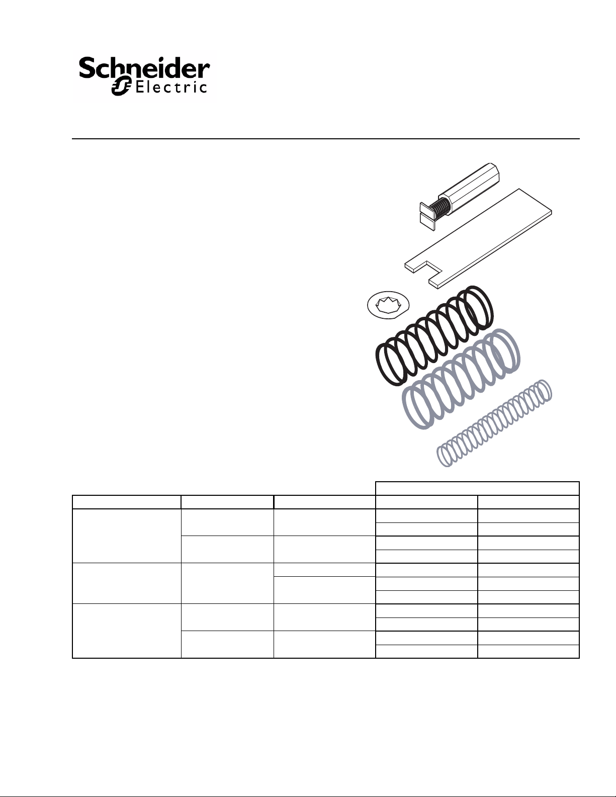
AV-7600-1
Hydraulic Actuator Valve Linkage Kit
for VB-7XXX Series Valves
General Instructions
Spring Selection and Calibration
The springs in the AV -7600-1 kit are used with selected actuators for specific valves and/or valve sizes. Reference Table-1.
Table-1 Spring Usage for VB-7xxx Valves.
MP-521x Series
Valve Size Spring(s) Controller Calibration
VB-721x
VB-725x
VB-727x
Normally Open
VB-731x - Mixing
2x - Diverting
VB-73
VB-7332 - Sequencing
VB-722x, VB-726x
& VB-7
Normally Closed
a
MA, MF, MP-541x, and MP-55xx actuator positioning is independent of spring selected.
b
When using a Schneider Electric System 8000 controller or a 4 to 20 mA signal across a 500 Ohm resistor to get the proper voltage.
c
The black spring used on a normally open valves may eliminate the need for positive positioning actuators.
d
PNV-145-48 Blue spring is not part of this kit. It is only required for controllers limited to 10 volts or 20 mA maximums.
e
Used with signals limited to 10V such as 0 to 10 Vdc and 4 to 20 mA across a 500 Ohm resistor. Note a reduced control range.
f
The small unpainted spring may be added to provide addition close off.
28x
1/2” to 1-1/4”
(15 to 32 mm)
1/2” thru 2”
(15 to 50 mm)
1/2” thru 2”
(15 to 50 mm)
1/2” thru 1-1/4”
(15 to 32 mm)
1/2” thru 2”
(15 to 50 mm)
Large Unpainted
c
Black
(highest close off)
Large Unpainted 7.5 Volts 6 to 9 Volts
d
PNV-145-48
small unpainted booster
Large Unpainted
Large and small unpainted
ooster (highest close off)
b
Blue with
f
e
7.5 Volts 6 to 9 Volts
15 mA 12 to 18 mA
5.0 Volts 3.5 to 6.5 Volts
10 mA 7 to 13 mA
7.5 Volts 7to 8 Volts
15 mA 14 to 16 mA
7.5 Volts 6 to 9 Volts
15 mA 12 to 18 mA
7.5 Volts 6 to 9 Volts
15 mA 12 to 18 mA
a
b
Nominal Control Range
b
Printed in U.S.A. 4/10 © Copyright 2010 Schneider Electric All Rights Reserved. F-26235-5
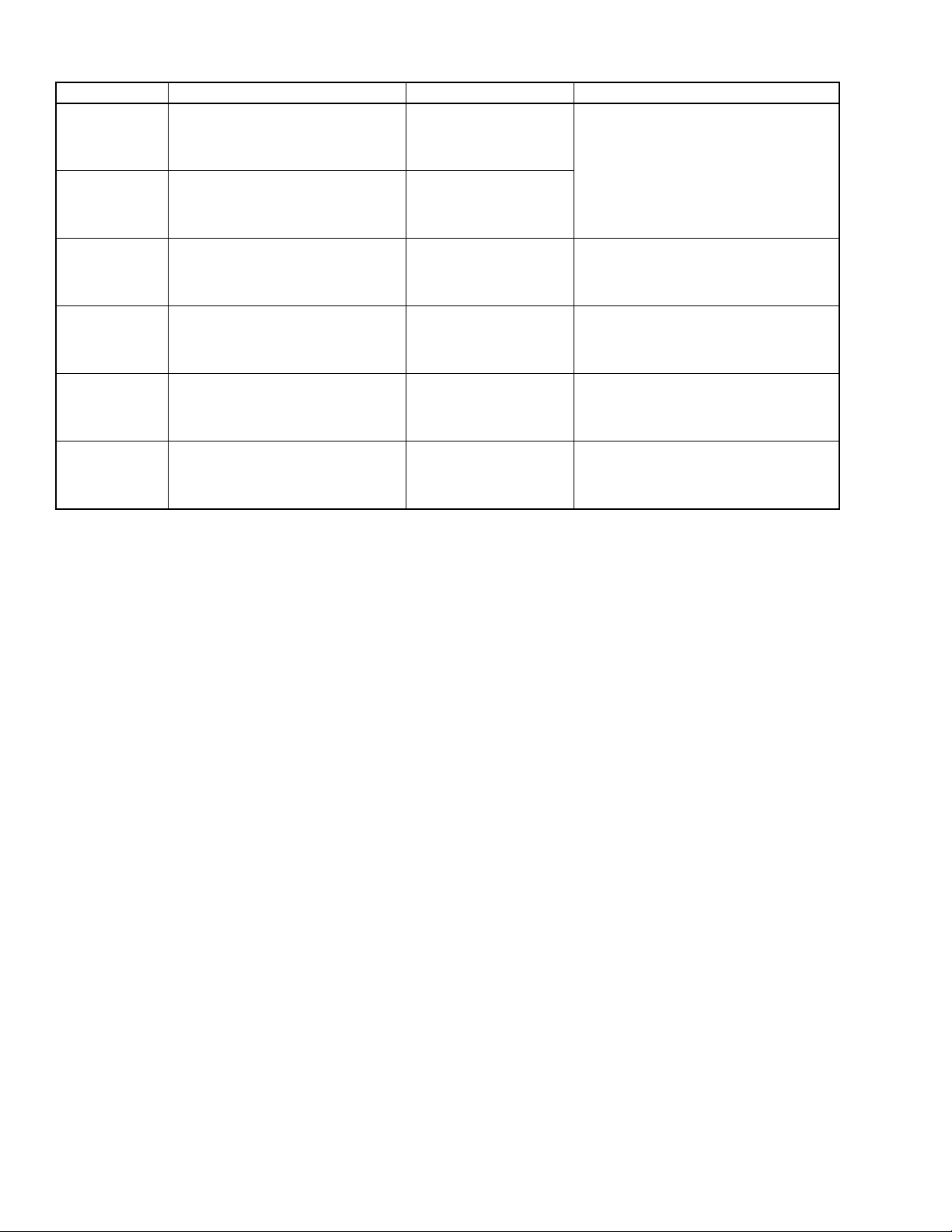
Applicable Literature
F-Number Description Audience Purpose
– Sales Personnel
F-23638 Cross-Reference Guide
F-26789 Component Cross-Reference Guide
F-21683 Reference Manual
F-27383 Pneumatic Products Catalog
F-26080 EN-205 Water System Guidelines
F-26280
AV-601 Linkage Extension Kit General
Instructions
– Application Engineers
– Installers
– Service Personnel
– Sales Personnel
– Application Engineers
– Installers
– Service Personnel
– Sales Personnel
– Application Engineers
– Installers
– Service Personnel
– Sales Personnel
– Application Engineers
– Installers
– Service Personnel
– Application Engineers
– Installers
– Service Personnel
– Start-up Technicians
– Application Engineers
– Installers
– Service Personnel
– Start-up Technicians
Provides specifications and part number cross
referencing of phased out controls with the
new Schneider Electric controls.
Provides a collection of general and
installation instructions and other reference
documents
Provides descriptions and specifications for
the Schneider Electric components.
Describes Schneider Electric approved water
treatment practices.
Describes the linkage extension kit’s features,
specifications and possible applications.
Provides step-by-step installation instructions.
2 © Copyright 2010 Schneider Electric All Rights Reserved. F-26235-5
SPECIFICATIONS
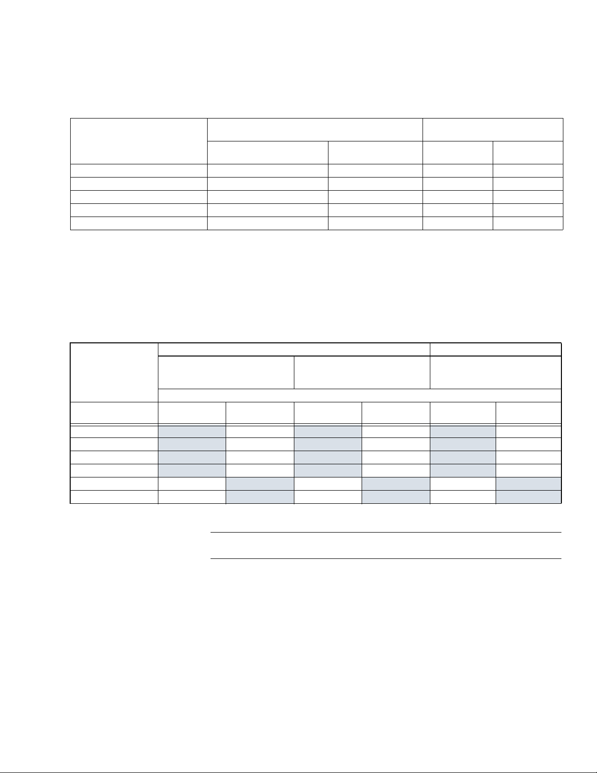
Temperature Restrictions
Verify that temperature of the media in the valve versus the ambient temperature at the
actuator does not exceed the ratings shown in
Table-2 Restrictions on the Maximum Ambient Temperature for the Valve Actuator.
Max. Temperature of Media in °F
(°C)
in the Valve Body (Check Ratings
a
Maximum allowable ambient temperature of the actuator.
of the Valve)
366 (180) Do Not Use 88 (31) 90 (32) 90 (32)
340 (171) Do Not Use 93 (34) 100 (38) 100 (38)
281 (138) Do Not Use 103 (39) 115 (46) 140 (60)
181 (83) Do Not Use 120 (48) 140 (60)
80 (26) 140 (60)
Max. Ambient Temperature in °F (°C)
of MF-5x1x, MP-541x, or MP-551x
AV-7600-1 Only for Chilled
Water Applications Only
a
AV-7600-1
& AV-601
140 (60)
The AV-601 linkage extension provides thermal insulation between the valve and actuator.
It
is required for all heating valves with MF-5x13, MP-541x, MP-551x, MPR-561x,
MPR-571x, and MPR-581x actuators. It is recommended for cooling valves with MF-5x13,
MP-541x, MP-551x, MPR-561x, MPR-571x, and MPR-581x actuators. It is also used for
higher ambient and fluid temperatures with MA-521x and MP-521x actuators. Re fer to
AV-601 Linkage Extension Kit General Instructions, F-26280 for installation procedures.
Table-2.
a
Max. Ambient Temperature in °F (°C)
of MA-521x or MP-521x
AV-7600-1 Only
a
a
140 (60)
AV-7600-1
& AV-601
140 (60)
140 (60)
a
a
a
Table-3 Nominal Hydraulic Two-Way Valve Close Off Ratings. (See Table-1 for controller calibration.)
Spring Closes (Normally Closed) Spring Opens (Normally Open)
MP-5x1x Analog Actuators:
6 to 9, 0 to 10 Volt, and 4 to 20mA
Close Off Rating with Springs Shown Psi (kPa)
Valve Size Unpainted
1/2 inch (15mm) 130a (900)
3/4 inch (20 mm) 80 (550) 180 (1200) 130 (910) 200 (1300) 80 (550) 200 (1300)
1inch (25 mm) 40 (270) 60 (410) 50 (340) 90 (620) 40 (270) 150 (1000)
1-1/4 inch (32 mm) 25 (170) 40 (270) 35 (240) 60 (410) 25 (170) 90 (620)
1-1/2 inch (40 mm) 15 (100) 25 (170) 20 (140) 35 (240) 15 (100) 60 (410)
2 inch (50 mm) 6 (40) 14 (95) 10 (70) 20 (140) 6 (40) 35 (340)
a
Shaded area as shipped from factory.
Unpainted with
Booster
250 (1700) 200 (1300) 250 (1700) 130 (910) 250 (1700)
MA-521x & MF-521x
Digital Actuators:
2 Position and Floating
Unpainted
Unpainted with
Booster
All Actuators:
Analog, 2 Position, and Floating
Unpainted Black
Note: Close off ratings describe only the differential pressure which the actuator can close
off with adequate seating force. Consult valve body specifications for limitations.
F-26235-5 © Copyright 2010 Schneider Electric All Rights Reserved. 3

Table-4 Nominal Hydraulic Three-Way Valve Close Off Ratings. (See Table-1 for controller calibration.)
Close Off Rating Psi (kPa)a Differential pressure between A & B ports
Spring Closes “A” Port Actuator Closes “B” Port
Mx-521x Analog Actuators:
6 to 9 and 0 to 10 Volt, 4 to 20 mA
Valve Size
1/2 inch (15mm) 130 (900) 250 (1700) 200 (1300) 250 (1700) 130 (910) 250 (1700)
3/4 inch (20 mm) 80 (550) 250 (1700) 130 (910) 250 (1700) 80 (550) 250 (1700)
1inch (25 mm) 40 (270) 250 (1700) 50 (340) 250 (1700) 40 (270) 250 (1700)
1-1/4 inch (32 mm) 25 (170) 250 (1700) 35 (240) 250 (1700) 25 (170) 250 (1700)
1-1/2 inch (40 mm) 15 (100) 250 (1700) 20 (140) 250 (1700) 15 (100) 250 (1700)
2 inch (50 mm) 10 (70) 250 (1700) 14 (95) 250 (1700) 10 (70) 250 (1700)
a
VB-7332, 1/2 inch sequencing valves close off 35 Psi (240 kPa) on both ports.
b
Factory shipments have unpainted large springs. For 0 to 10 Volt and 4 to 20 mA controllers use blue and booster springs. (See Table-1.)
VB-731x
Mixing
VB-732x
Diverting
b
MA-521x & MF-521x
Digital Actuators:
2 Position and Floating
VB-731x
Mixing
VB-732x
Diverting
Analog, 2 Position, and Floating
All Actuators:
VB-731x
Mixing
VB-732x
Diverting
Note: Close off ratings describe only the differential pressure which the actuator can close
off with adequate seating force. Consult valve body specifications for limitations.
INSTALLATION
Inspection Inspect the package for damage. If damaged, notify the appropriate carrier immediately.
If undamaged, open the package and inspect the device for obvious damage. Return any
damaged products.
Requirements • Tools:
– Screwdriver appropriate for slotted spring compression screw (not provided)
– Linkage wrench (provided) or TOOL-20-1, packing and linkage wrench (not
provided)
• Installer must be a qualified, experienced technician
Caution:
• Avoid locations where excessive moisture, corrosive fumes, or vibration is present.
• Install all two-way valves so that they close against the flow. An arrow on the valve body
or a tag indicates the proper flow direction.
• Always install three-way mixing valves with two inlets and one outlet.
• The actuator must be above the center line of the valve. For steam applications mount
the actuators above the valve body at 45° from vertical.
Linkage Kit Installation
The AV-7600-1 linkage kit used on VB-7xxx series valve bodies requires no stem height setting.
Procedure
The linkage kit is assembled onto the VB-7xxx valve body with the stem in the up position.
1. Select the appropriate spring(s) as detailed in Figure-1.
2. Thread the hexagon coupler onto the valve stem all the way to the bottom of the stem thread, finger-tight (Figure-1). Pull the valve stem completely up.
4 © Copyright 2010 Schneider Electric All Rights Reserved. F-26235-5

Spring
Compresion
Screw
Hexagon Coupler
Spring Retainer
Valve Stem
1/16" (1.6 mm)
Max.
Figure-1 Installation of Hexagon Coupler and Spring Compression Screw.
Spring
Screwdriver
Linkage Wrench
(Hold to prevent turning.)
2-1/4" (57 mm)—VB-721X
2-3/16" (56 mm)—VB-722X & VB-73XX
Spring Retainer
(Turn 45 degrees to
lock in place.)
Turn until Spring Compression
Screw bottoms firmly on
valve stem.
Figure-2 Completing Linkage Kit Assembly to Valve.
Caution: The hexagon coupler must reach to within 1/16” (1.6 mm) of the smooth section
of the stem to assure proper seating. Do not use the Spring Compression Screw to run the
Hexagon Coupler down.
3. On normally closed valves (1-1/2” [40 mm] to 2” [50 mm] mandatory) slip the small unpainted booster spring over the stem.
4. Start the spring(s) compression screw one turn or more into the hexagon coupler.
5. Slip the spring over the coupler and the spring compression screw.
6. Place the retainer over the screw. Twist the retainer 45° to lock it in place.
7. Insert the linkage wrench (supplied with kit, also included on TOOL-20-1) through the spring coils about 3 coils from the bottom to hold hexagon coupler.
8. Hold the wrench from turning and tighten the spring compression screw. To establish
proper linkage height, run the spring compression screw down until the screw end
bottoms firmly on the stem top (
Figure-2).
F-26235-5 © Copyright 2010 Schneider Electric All Rights Reserved. 5

9. Confirm the stem height setting (Figure-2):
Spring Retainer
Mounting Nut
Spring
Compression
Screw
Hexagon Coupler
Actuator
(purchase separately)
Booster Spring
(Small Unpainted)
Spring
(Large)
Figure-3 Assembly of Linkage Kit onto VB-7xxx Series Valve.
• 2-5/16” (59 mm) maximum after installation on stem up open valves (VB-721x).
• 2-7/32” (56 mm) maximum on stem up closed valves (VB-722x) or three-way valves
(VB-73xx).
10. Center the spring on top and bottom to assure smooth actuator operation. See Figure-3 for total assembly components required.
MAINTENANCE
The actuator linkage requires no maintenance.
For linkage removal, insert wrench through springs and hold. Remove spring compression
screw and p
Regular maintenance of the total system is recommended to assure sustained, optimum
performance. Hard water leaves abrasive deposits and reduces component life. To
maximize valve life, consult EN-205 Water System Guidelines, F-26080.
arts.
6 © Copyright 2010 Schneider Electric All Rights Reserved. F-26235-5

FIELD REPAIR
1
2
5
6
3
4
Figure-4 AV-7600-1 Hydraulic Actuator Valve Linkage Kit.
Individual parts of the actuator linkage are not repairable. Replace an inoperative actuator
linkage with a functional unit or replace individual parts as necessary (
Table-5 AV-7600-1 Replacement Parts.
Item (See Figure-4) Part No. Description
1 P4-14 Large Unpainted Spring
2 P4-14-10-1
3 PNV-145-45 Large Black Spring
4 YBA-559 Spring Retainer
NYBA-80 Stem Coupler (hexagon)
5
6 NYBA-82 Linkage Wrench
NYBA-79
Table-5 and Figure-4).
Small Unpainted Booster
Spring
Spring Compression
Screw
F-26235-5 © Copyright 2010 Schneider Electric All Rights Reserved. 7

On October 1st, 2009, TAC became the Bui ldings business of its par ent c om pany Schneider El ectric. This document reflect s the visual identity of Schneider El ectric,
however there remains ref ere nces to TAC as a corporate brand in the body copy. As each document is updated, the body copy will be changed to reflect appropriate
corpo rate bra nd ch a nges.
Copyright 2010, Schneider Electric
All brand names, trademarks and registered
trademarks are the property of their respective
owners. Information contained within this
document is subject to change without notice.
F-26235-5
 Loading...