

Page 1
APPLICATION
This General Instruction sheet provides the information
necessary to field assemble AV-650 gear train actuator
linkage to Honeywell V-501 1 two-way and V -5013 three-way
(1/2 to 3") valve bodies, with a 1-3/8" bonnet.
SPECIFICATIONS
Minimum Actuator Torque Required: 50 lb.-in. (5.6 N-m).
Actuator must have 180° stroke.
Stem Force: 150 lb. (667 N). Close-Off pressure Ratings for Gear TrainActuatros: See Table 1.
Table-1 Close-off Pressure Ratings
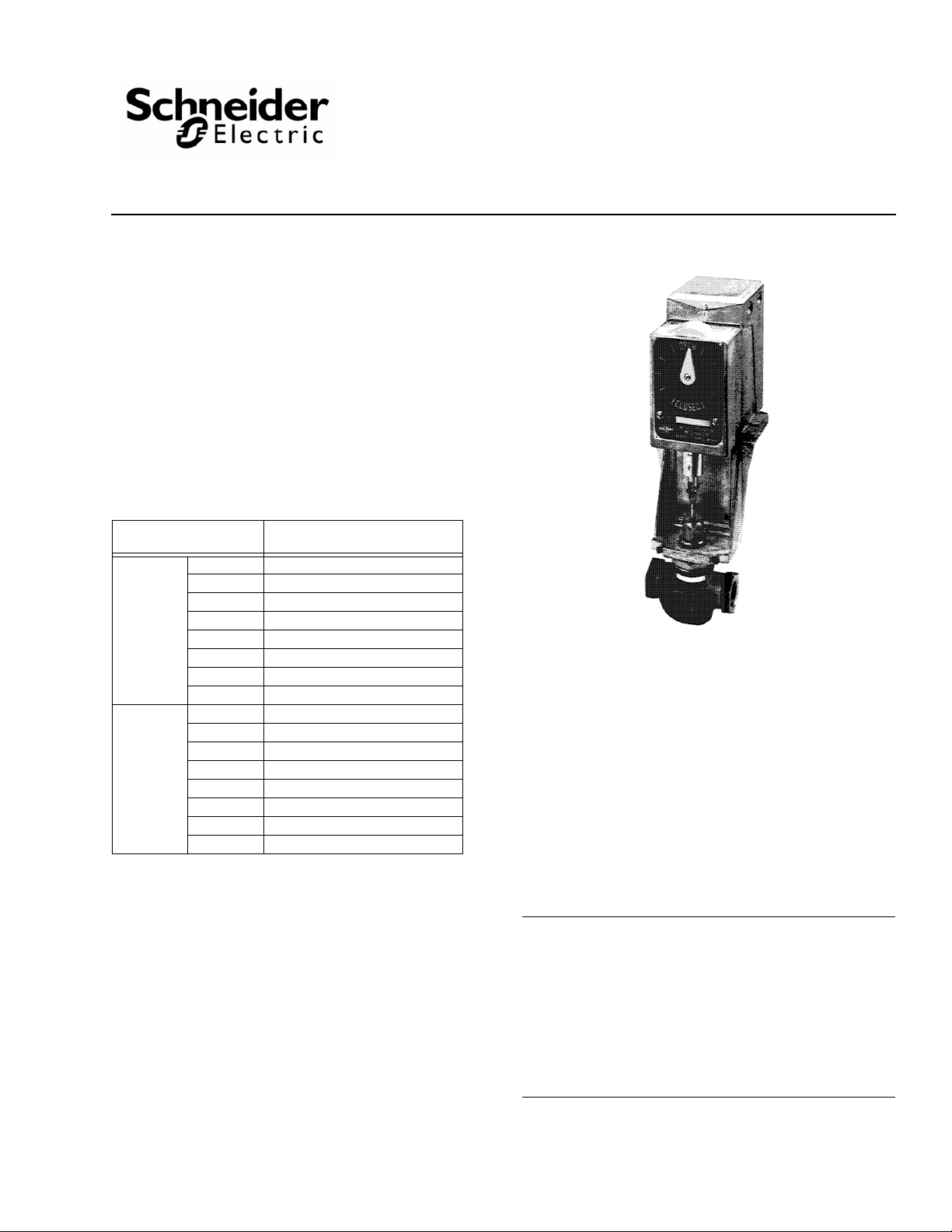
Valves Using Electric
AV-650
Gear Train Actuator Linkage
General Instructions
Valve Body
1/2" 150 (1034)
3/4" 150 (1034)
1" 150 (1034)
V-5011
V-5013
OPTIONS None
ACCESSORIES Non
1-1/4" 132 (910)
1-1/2" 85 (586)
2" 52 (359)
2-1/2" 30 (207)
3" 19 (131)
1/2" 150 (1034)
3/4" 150 (1034)
1" 150 (1034)
1-1/4" 137 (945)
1-1/2" 92 (634)
2" 63 (434)
2-1/2" 30 (207)
3" 21 (145)
Close-Off Pressure Ratings
ps
i (kPa)
e
PRE-INSTALLATION
Inspection
Visually inspect the carton for damage. If damaged, notify the
appropriate carrier immediately. If undamaged, open the
carton and visually inspect the device for obvious defects.
Return damaged or defective products.
Required Installation Items
• AV-650 linkage
• Actuator
• Valve body
• Tools:
Allen wrench
Crescent wrench
Screwdriver
INSTALLATION
Caution:
• Installer must be a qualified, experienced technician.
• Install all globe-type valves with pressure under seat. An
arrow on the valve body indicates the proper flow
direction.
• Always install three-way mixing valves with two inlets
and one outlet.
• Always install three-way diverting valves with one inlet
and two outlets.
Printed in U.S.A. 6-10 © Copyright 2010 Schneider Electric All Rights Reserved. F-21679-3
Page 2
Assembly of Mounting Bracket to Valve Body (See Figure 1)
1. Place mounting bracket on valve body.
2. Tighten the three set screws in the base of the mounting bracket.
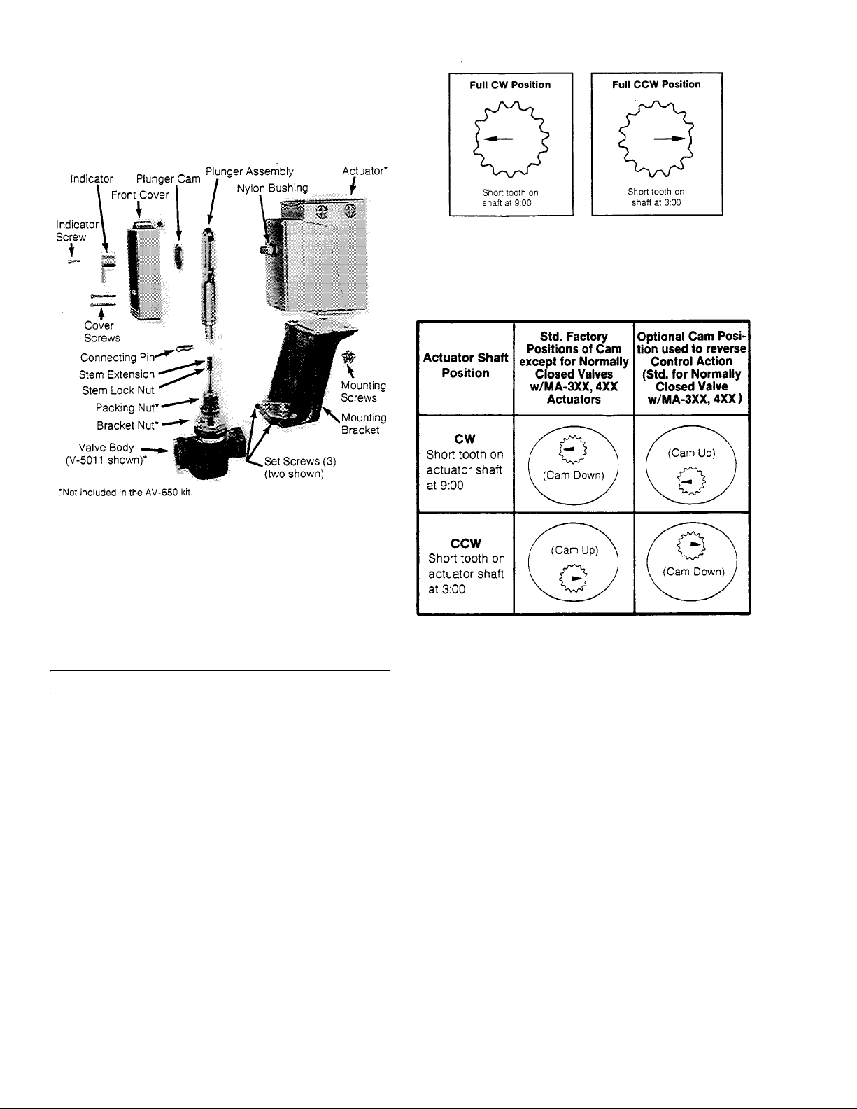
Figure-2 Actuator Shaft Position (Front View).
Table 2. Cam Position On Actuator Shaft
Figure-1 Valve Actuator Linkage AV-650 for Honeywell Valve
Bodies V-5011 & V-5013 (1/2 thru 3") with a 1-3/8" Bonnet.
Assembly of Stem Extension on Valve Stem &
Actuator on Mounting Bracket (See Figure 1)
1. Thread stem lock nut and stem extension down fully on valve stem.
2. Place actuator on mounting bracket. Fasten actuator to mounting bracket with three 1/4-20 screws provided.
Caution: Do not tighten mounting screws.
3. Place nylon bushing on actuator shaft.
Cam Positioning for Control System Application
1. Determine actuator shaft position from Figure 2 (no power
to actuator). If actuator shaft position (indicated by short
tooth) is not in the 9:00 or 3:00 position, power the actuator
until this is the case. The actuator shaft of spring retu rn and
MC actuator will be in the 9:00 or 3:00 position with no
power to the actuator .
2. Determine the cam position on the actuator shaft by
referring to Figure 2 and Table 2 and considering the
application. Actuators are normally shipped from the
factory for direct acting heating applications. A call for
heat will cause the valve to open. On system checkout or
field assembly, the applications may vary.
3. Place the cam in plunger and slip on the actuator shaft.
Assuring Proper Close-Off of Valve
For normally open two-way valve assemblies, spring return actuators:
1. With actuator in its spring return position, the cam should be pointing up (refer to Figure 2 and Table 2).
2. Power actuator so that cam is now pointing down.
3. With valve stem down, screw stem extension into plunger until holes in stem extension and plunger line up.
4. Turn stem extension up two full turns.
5. Raise actuator until connecting pin can be inserted through plunger and stem extension holes.
6. Tighten actuator mounting screws.
7. Tighten lock nut against stem extension.
2 © Copyright 2010 Schneider Electric All Rights Reserved. F-21679-3
Page 3

For normally closed two-way valve assemblies, spring return actuators:
1. With actuator in its spring return position, the cam should be pointing down (refer to Figure 2 and Table 2).
2. With valve stem down, screw stem extension into plunger until holes in stem extension and plunger line up.
3. Turn stem extension up two full turns.
4. Raise actuator until connecting pin can be inserted through plunger and stem extension holes.
5. Tighten actuator mounting screws.
6. Tighten lock nut against stem extension.
For two-way valve assemblies, non-spring return actuators:
1. Cam should be pointing down (refer to Figure 2 and Table2); if not, power actuator until holes and stem extension and plunger line up.
2. With valve stem down, screw stem extension into plunger until holes in stem extension and plunger line up.
3. Turn stem extension up two full turns.
4. Raise actuator until connecting pin can be inserted through plunger and stem extension holes.
5. Tighten actuator mounting screws.
6. Tighten lock nut against stem extension.
For three-way valve assemblies:
1. Cam should be pointing up (refer to Figure 2 and T able 2); if not power actuator until cam is in this position.
2. With valve stem up, screw stem extension into plunger until holes in stem extension and plunger line up.
3. Turn stem extension down 1-1/2 turns.
4. Power actuator (or lower actuator plunger by tipping actuator forward) until connecting pin can be inserted through plunger and stem extension holes.
5. Tighten actuator mounting screws.
6. Check compression per note below. If compression is insufficient, stem extension should be adjusted an additional 1/2 turn down.
7. Tighten lock nut against stem extension.
Note: Compression Check
Check plunger spring compression (Figure 3). The length of
stem should be adjusted so valve disc seats before actuator
reaches the end of closing stroke. Balance of actuator travel
is taken up in plunger spring compression and should be
approximately 1/16" (1.6 mm). This provides pressure on disc
in closed position and also compensates for disc and seat
wear. On three-way valves spring compression must be
provided on both upper and lower seats.
Figure-3 Plunger Spring Compression.
MAINTENANCE
Regular maintenance of the total system is recommended to
assure sustained optimum performance.
To Complete Assembly
1. Place front cover over plunger assembly and fasten to actuator with two self-tapping screws.
2. Install position indicator to end of actuator shaft to correspond with point of cam position and secure with screw.
F-21679-3 © Copyright 2010 Schneider Electric All Rights Reserved. 3
Page 4

On October 1st, 200 9, TAC became the Buildings business of its paren t comp any Schneider Electric. This docu m ent reflects the visual i dentity of Schneider Electri c,
however there remains references to TAC as a co rporate brand in the body copy. As each document is updated, the body copy will be cha nged to ref lect appr opriate
corpo rate br a nd changes.
Copyright 2010, Schneider Electric
All brand names, trademarks and registered
trademarks are the property of their respective
owners. Information contained within this
document is subject to change without notice.
F-21679-3
 Loading...