

Page 1

Presentation
Variable speed drives
for asynchronous motors
0
Altivar 11
561250
1
3
2
4
2
5
7
8
6
Schneider Electric
Page 2

Presentation (continued)
Variable speed drives
for asynchronous motors
Altivar 11
Applications
The Altivar 11 is a frequency inverter for 3-phase squirrel cage asynchronous motors
rated between 0. 18 kW and 2.2 kW.
There are three types of po wer supply:
# 100 V to 120 V single phase
# 200 V to 240 V single phase
# 200 V to 230 V 3-phase
The Altivar 11 incorporates specif ic features for loca l markets (Europe range,
America range, Asia range) and has functions suitable for the most common
applications, including:
# Horizontal materials hand ling (small conveyors, etc)
# Ventilation, pumping, access control, automatic doors
# Specia l machines (m i xer s, wa sh in g ma chines, cen trifuge s, et c )
Functions
The main functi ons incorporated in the Altivar 11 drive are:
# Starting and speed co ntrol
# Reversal of operation direction
# Accele ration, de ce le ra ti on , sto pp ing
# Motor and drive protection
# 2-wire/3-wire control
# 4 preset speeds
# Saving the configuration in the drive
# d.c. injection on stopping
# Ramp switching
# Catching a spinning load
# Local co ntrols (A sia range only)
Several functions can be assigned to one logic input.
Standard versions
The Altivar 11 offer consists of 3 ranges designed for 3 different markets:
# Europe range: ATV 11/U//M2E (items , )
5Single phase 240 V power supply
5Positive lo gic operation
5Inte gra ted class B EMC filter
# America range: ATV 11/U////U (items , , , )
5Power supplies: 120 V single phase, 240 V single phase or 230 V 3-phase
5Positive lo gic operation
5Meets current requirement in standard NEC 1999 208 V
# Asia range: ATV 11/U////A (items , )
5Power supplies: 120 V single phase, 240 V single phase or 230 V 3-phase
5Positive or negative logic op eration
5Local cont rols: Run and Stop keys, and poten tiometer
1 2
1 2 3 4
5 6
0
Characteristics:
pages 60251/2 to 60251/5
Schneider Electric
References:
pages 60252/2 to 60252/5
Altivar 11 driv es are supplied either with heatsink (ite ms ,,) for normal
environments and ventilated enclosures, or on a base plate (items , , ) for
mountin g o n a ma ch ine f r ame, when th e s ize of t he f ram e en ab le s diss ip at i on of th e
heat.
Electromagnetic compatibility EMC
The incorporation of EMC filters in AT V 1 1
machines and provides an economical means of meeting
ATV 11
/U////U and ATV 11 /U////A drives are available without EMC filter. Filters
are available as an option for customer assembly, if conformity to EMC standards is
required.
/U//M2E drives simplifies installation of
1 3 5
2 4 6
&marking requirements.
Options
The drive only communicates, in point-to-point mode, with the following tools and
software:
# PowerSuite advanced dialogue solution :
5PowerSuite software workshop for configuring the drive (item ),
5PowerSuite for Pocket PC (item ),
5Converter for connecting a PC or a Pocket PC
The following options can be used with the Altivar 11 drive:
# Braking module connected to the drive’s DC bus
# Braking resistors, for diss ipating the energy returned to th e drive when the motor
is operating as a generator
# EMC rad io interference input filters
# Plates for mounting on rail
# Adaptor plate for replacing an Al tivar 08 drive
# Plate for EMC mounting, earthing the cable shielding.
Dimensions:
pages 60253/2 and 60253/3
8
Schemes:
pages 60254/2 and 60254/3
7
3
Page 3

References
Variable speed drives
550483
ATV 11 HU18M2E
for asynchronous motors
Altivar 11
ATV 11//////E Europe range
Drives with heatsink (frequency range from 0 to 200 Hz)
Motor Line supply
Power
indicated
on
plate
kW A A A W kg
(1)
Max. line
current for
prospecti ve
Isc
1 kA
Single phase supply voltage: 200…240 V 50/60 Hz
0.18 2.9 1.1 1.6 12 ATV 11HU05M2E 0.900
0.37 5.3 2.1 3.1 20.5 ATV 11HU09M2E 1.000
0.55 6.3 3 4.5 29 ATV 11HU12M2E 1.100
0.75 8.6 3.6 5.4 37 ATV 11HU18M2E 1.100
Altivar 11
Permanent
output
current (2)
Max.
transient
current (3)
Power
dissipated
at nominal
load
Reference
(4)
Weight
0
550485
ATV 11 PU18M2E
550489
ATV 11 HU41M2E
1.5 14.8 6.8 10.2 72 ATV 11HU29M2E
2.2 20.8 9.6 14.4 96 ATV 11HU41M2E
(5)
(5)
1.800
1.800
Drives on base plate (frequency r ange from 0 to 200 Hz)
Motor Line supply
Power
indic ated
on
plate
kW A A A W kg
(1)
Max. line
current for
prospecti ve
Isc
1 kA
Single phase supply voltage: 200…240 V 50/60 Hz
0.37 5.3 2.1 3.1 20.5 ATV 11PU09M2E 0.900
0.55 6.3 3 4.5 29 ATV 11PU12M2E 0.900
0.75 8.6 3.6 5.4 37 ATV 11PU18M2E 0.900
(1) Line voltage 230 V.
(2) The current value is given for a 4 kHz switching frequency.
(3) For 60 seconds.
(4) Drive supplied with an integrated EMC filter which cannot be disconnected.
(5) With integrated fan.
Altivar 11
Permanent
output
current (2)
Max.
transient
current (3)
Power
dissipated
at nominal
load
Reference
(4)
Weight
4
Presentation:
pages 2 and3
Characteristics:
pages 8 to11
Dimensions:
pages 12 and 13
Schemes:
pages 14 and 15
Schneider Electric
Page 4

References
Variable speed drives
550484
ATV 11HU18M2U
550486
for asynchronous motors
Altivar 11
ATV 11//////U America range
Drives with heatsink (frequency range from 0 to 200 Hz)
Motor Line supply Altivar 11
Power
indicated
on
plate
kW/HP A A A W kg
Single phase supply voltage: 100…120 V 50/60 Hz
0.18/0.25 6 1.6 2.4 14.5 ATV 11HU05F1U 0.900
0.37/0.5 92.43.623ATV 11HU09F1U 1.000
0.75/1 18 4.6 6.3 43 ATV 11HU18F1U
Single phase supply voltage: 200…240 V 50/60 Hz
0.18/0.25 3.3 1.6 2.4 14.5 ATV 11HU05M2U 0.900
0.37/0.5 62.43.623ATV 11HU09M2U 1.000
0.75/1 9.9 4.6 6.3 43 ATV 11HU18M2U
1.5/2 17.1 7.5 11.2 77 ATV 11HU29M2U
2.2/3 24.1 10.6 15 101 ATV 11HU41M2U
3-phase supply voltage: 200…230 V 50/60 Hz
0.18/0.25 1.8 1.6 2.4 13.5 ATV 11HU05M3U 0.900
Max. line
current (1)
Permanent
output
current (2)
Max.
transient
current (3)
Power
dissipated
at nominal
load
Reference
(4)
(5)
(5)
(5)
(5)
Weight
1.800
1.100
1.800
1.800
0
ATV 11PU18M2U
550490
ATV 11HU41M2U
550491
0.37/0.5 3.6 2.4 3.6 24 ATV 11HU09M3U 1.000
0.75/1 6.3 4.6 6.3 38 ATV 11HU18M3U
1.5/2 11 7.5 11.2 75 ATV 11HU29M3U
2.2/3 15.2 10.6 15 94 ATV 11HU41M3U
(5)
(5)
(5)
1.100
1.800
1.800
Drives on base plate (frequency range from 0 to 200 Hz)
Motor Line supply Altivar 11
Power
indicated
on
plate
kW/HP A A A W kg
Single phase supply voltage: 100…120 V 50/60 Hz
0.37/0.5 92.43.623ATV 11PU09F1U 0.900
Single phase supply voltage: 200…240 V 50/60 Hz
0.37/0.5 62.43.623ATV 11PU09M2U 0.900
0.75/1 9.9 4.6 6.3 43 ATV 11PU18M2U 0.900
3-phase supply voltage: 200…230 V 50/60 Hz
0.37/0.5 3.6 2.4 3.6 24 ATV 11PU09M3U 0.900
0.75/1 6.3 4.6 6.3 38 ATV 1 1PU18M3U 0.900
(1) The line current value is given for the measurement conditions indicated in the table below.
Drive rating Prospective Isc Line voltage
ATV 11
ATV 11
ATV 11
(2) The current value is given for a 4 kHz switching frequency.
(3) For 60 seconds.
(4) Drive supplied without EMC filter. To order an EMC filter separately, see p age 60252/5.
(5) With integrated fan.
Max. line
current (1)
/UF1U 1 kA 100 V
/UM2U 1 kA 208 V
/UM3U 5 kA 208 V
Permanent
output
current (2)
Max.
transient
current (3)
Power
dissipated
at nominal
load
Reference
(4)
Weight
ATV 11HU41M3U
Presentation:
pages 2 and 3
Schneider Electric
Characteristics:
pages 8 to11
Dimensions:
pages 12 and 13
Schemes:
pages 14 and 15
5
Page 5

References
Variable speed drives
550488
ATV 11HU18M2A
550487
for asynchronous motors
Altivar 11
ATV 11//////A Asia range
Drives with heatsink (frequency range from 0 to 200 Hz)
Motor Line supply Altivar 11
Power
indicated
on
plate
kW A A A W kg
Single phase supply voltage: 100…120 V 50/60 Hz
0.18 6 1.4 2.1 14 ATV 11HU05F1A 0.900
0.37 9 2.4 3.6 25 ATV 11HU09F1A 1.000
0.75 18 4 6 40 ATV 11HU18F1A
Single phase supply voltage: 200…240 V 50/60 Hz
0.18 3.3 1.4 2.1 14 ATV 11HU05M2A 0.900
0.37 6 2.4 3.6 25 ATV 11HU09M2A 1.000
0.75 9.9 4 6 40 ATV 11HU18M2A 1.100
1.5 17.1 7.5 11.2 78 ATV 11HU29M2A
2.224.1101597ATV 11HU41M2A
3-phase supply voltage: 200…230 V 50/60 Hz
0.18 1.8 1.4 2.1 13.5 ATV 11HU05M3A 0.900
Max. line
current (1)
Permanent
output
current (2)
Max.
transient
current (3)
Power
dissipated
at nominal
load
Reference
(4)
(5)
(5)
(5)
Weight
1.800
1.800
1.800
0
ATV 11PU18M2A
550492
ATV 11HU41M2A
550493
0.37 3.6 2.4 3.6 24 ATV 11HU09M3A 1.000
0.75 6.3 4 6 38 ATV 11HU18M3A 1.100
1.5 11 7.5 11.2 75 ATV 11HU29M3A
2.215.2101594ATV 11HU41M3A
(5)
(5)
1.800
1.800
Drives on base plate (frequency r ange from 0 to 200 Hz)
Motor Line supply Altivar 11
Power
indic ated
on
plate
kW A A A W kg
Single phase supply voltage: 100…120 V 50/60 Hz
0.37 9 2.4 3.6 25 ATV 11PU09F1A 0.900
Single phase supply voltage: 200…240 V 50/60 Hz
0.37 6 2.4 3.6 25 ATV 11PU09M2A 0.900
0.75 9.9 4 6 40 ATV 11PU18M2A 0.900
3-phase supply voltage: 200…230 V 50/60 Hz
0.37 3.6 2.4 3.6 24 ATV 11PU09M3A 0.900
0.75 6.3 4 6 38 ATV 11PU18M3A 0.900
(1) The line current value is given for the measurement conditions indicated in the table below.
Drive rating Prospective Isc Line voltage
ATV 11
ATV 11
ATV 11
(2) The current value is given for a 4 kHz switching frequency.
(3) For 60 seconds.
(4) Drive supplied without EMC filter. To order an EMC filter separately, see page 60252/5.
(5) With integrated fan.
Max. line
current (1)
/UF1A 1 kA 100 V
/UM2A 1 kA 200 V
/UM3A 5 kA 200 V
Permanent
output
current (2)
Max.
transient
current (3)
Power
dissipated
at nominal
load
Reference
(4)
Weight
ATV 11HU41M3A
Presentation:
pages 2 and3
6
Characteristics:
pages 8 to11
Dimensions:
pages 12 and 13
Schemes:
pages 14 and 15
Schneider Electric
Page 6

References
Variable speed drives
550496
VW3 A5870
for asynchronous motors
0
Altivar 11
Options and accessories
Description For drives Reference Weight
Advanced dialogue solution
PowerSuite
Converter, for connecting a PC or
Pocket PC, equipped with PowerSuite
software
EMC input filters ATV 11HU05M2E
/
All ratings See page 60200/3 –
All ratin gs VW3 A11301 0.070
ATV 11HU09M2E
ATV 11HU12M2E
ATV 11HU18M2E
ATV 11HU05F1U/A
ATV 11HU09F1U/A
ATV 11HU05M2U/A
ATV 11HU09M2U/A
ATV 11HU18M2U/A
ATV 11HU29M2E
ATV 11HU41M2E
ATV 11HU18F1U/A
ATV 11HU29M2U/A
ATV 11HU41M2U/A
ATV 11HU05M3U/A
ATV 11HU09M3U/A
ATV 11HU18M3U/A
VW3 A11401 0.650
VW3 A11402 0.850
VW3 A11403 0.650
kg
550497
VW3 A5873
ATV 11HU29M3U/A
ATV 11HU41M3U/A
Braking module connected to the
DC bus
Braking resistors Not protected
Plates for mounting on
(width 35 mm)
(IP 00)
Protected
(IP 30)
rail
/
Adaptor plate for replacing Altivar 08 All ratin gs VW3 A11811 0.220
Earthing plate for EMC mounting All ratings VW3 A11831 0.100
All ratin gs VW3 A11701 0.250
ATV 11
/U05///(1)
ATV 11
/U09///(1)
ATV 11
/U12///(1)
ATV 11
/U18///(1)
ATV 11
/U29///(2)
ATV 11
/U41///(2) VW3 A58704 0.600
ATV 11
/U05///(1)
ATV 11
/U09///(1)
ATV 11
/U12///(1)
ATV 11
/U18///(1)
ATV 11
/U29///(2)
ATV 11
/U41///(2) VW3 A58733 2.000
ATV 11/U05///
ATV 11/U09///
ATV 11/U12///
ATV 11/U18M//
ATV 11HU18F1
ATV 11/U29///
ATV 11/U41///
VW3 A11404 0.850
VW3 A58702 0.600
VW3 A58732 2.000
VW3 A11851 0.220
/
VW3 A11852 0.300
550494
VW3 A11852
Presentation:
pages 2 and 3
Schneider Electric
Characteristics:
pages 8 to11
Ventilation kit (3) ATV 11HU18F1
(1) Minimum value of the resistor to be connected: 75 ohms.
(2) Minimum value of the resistor to be connected: 51 ohms.
(3) "Low noise" fan.
Dimensions:
pages 12 and 13
ATV 11HU18M/U
ATV 11HU29
ATV 11HU41///
Schemes:
pages 14 and 15
/
///
VW3 A11821 0.070
7
Page 7

Characteristics
Variable speed drives
for asynchronous motors
Altivar 11
Environment
Conformity to standards Altivar 11 drives have been developed to conform to the strictest international
EMC immunity
EMC conducted and radiated
emissions for drives:
All # IEC/EN 61800-3, environments: 2 (industrial supply) and 1 (public supply) restricted
ATV 11
/U05M2E to
ATV 11
/U18M2E
/U29M2E to
ATV 11
ATV 11
/U41M2E
ATV 11HU05M2E to
ATV 11HU41M2E
ATV 11HU05
ATV 11HU41
ATV 11HU05
& marking The drives bear & marking in accordance with the European low voltage directives
Produ ct certification
Degree of protection
Vibration resistance Drive without
Shock resistance
Ambient temperature
around the unit
Maximum operating altitude
Operating posit ion
Maximum permanent angle in relation to the normal vertical
mounting position
Storage
Operation
ATV 11HU41
rail option Conforming to IEC/EN 60068-2-6:
//U to
//U and
//A to
//A
standards and the recommendations relating to electrical industrial control devices
(IEC, EN), in particular:
EN 50178, EMC immunity and EMC conducted and radiated emissions.
# IEC/EN 61000-4-2 level 3
# IEC/EN 61000-4-3 level 3
# IEC/EN 61000-4-4 level 4
# IEC/EN 61000-4-5 level 3 (power access)
# IEC/EN 61800-3, environments 1 and 2
distribution
# EN 55011, EN 55022 class B, 2 to 12 kHz for motor cable lengths
65 m and class A (g roup 1), 2 to 16 kHz for lengths 6 10 m
# EN 55011, EN 55022 class B, 4 to 16 kHz for motor cable lengths
65 m and class A (g roup 1), 4 to 16 kHz for lengths 6 10 m
# With additional EMC filter: EN 55011, EN 55022 class B, 2 to 16 kHz for motor
cable lengths
# With additional EMC filter: EN 55011, EN 55022 class B, 2 to 16 kHz for motor
cable lengths
(73/23/EEC and 93/68/EEC) and EMC (89/336/EEC)
UL, CSA, NOM 117 and C-TICK
IP 20
- 1.5 mm peak from 3 to 13 Hz
- 1 gn from 13 to 200 Hz
15 gn for 11 ms conforming to IEC/EN 60068-2-27
5…93% without condensation or dripping water, conforming to IEC 60068-2-3
°C - 25…+ 65
°C - 10…+ 40,
- 10…+ 50 : removing the protective cover from the top of the drive
Up to + 60 with current derating of 2.2% per °C above 50 °C
m 1000 without derating (above this, derate the current by 1% per additional 100 m)
620 m and class A (group 1), 2 to 16 kHz for lengths 6 50 m
65 m and class A (group 1), 2 to 16 kHz for lengths 6 20 m
0
Drive characteristics
Output frequency range Hz 0…200
Switching frequency
Speed range
Transient overtorque
Braking torque
Maximum transient current
Voltage/frequency ratio
Frequency loop gain
Slip compensation
Presentation:
pages 2 and3
8
References:
pages 4 to 7
kHz 2…16
1…20
150% of the nominal motor torque
- 20% of the nominal motor torque without braking resistor at no-load with the
“deceleration ramp adaptation” function enabled
- 80% of the nominal motor torque with braking resistor (available as an option) at noload
- Up to 150% of the nominal motor torque with braking resistor (available as an option)
at high inertia
150% of the nominal drive current for 60 seconds
Sensorless flux vector control with PWM motor control signal (1)
Factory-set for most constant torque applications
Factory-set with the speed loop stability and gain
Possible correction for machines with high resistive torque or high inertia, or for
machines with fast cycles
(1) Pulse width modulation
Dimensions:
pages 12 and 13
Factory-set, according to the rating of the drive (adjustment possible)
Schemes:
pages 14 and 15
Schneider Electric
Page 8

Characteristics (continued)
Variable speed drives
for asynchronous motors
Altivar 11
Electrical characteristics
Power supply Voltage V 200 - 15% to 240 + 10% single phase for ATV 11/U//M2/
Frequency Hz 50 ± 5% or 60 ± 5%
Isc
Output voltage
Maximum connecti on capacity
of the power supply, the motor
and the braking module
Max. length of motor cables
Electrical isolation
Available internal supplies
Analog input AI1
Logic inputs LI
DO output
Relay outputs (RA-RC)
Maximum I/O connection capacity
Acceleration and deceleration ramps
Braking to a standstill
Main protection and safety features of the drive
Motor protection
Insulation resistance to earth
Frequency resolution
Time constant for reference change
Drive ATV 11
U12M
Drive ATV 11
U18F1/, U29///, U41///
Positive logic
Negative logic
/U05///, U09///,
//, U18M//
/
(1)Pulse width modulation
200 - 15% to 230 + 15% 3-phase pour ATV 11/U//M3/
100 - 15% to 120 + 10% single phase for ATV 11/U//F1/
A £ 1000 (prospective short-circuit current at the connection point) for single phase
power supply
£ 5000 (prospective short-circuit current at the connection point) for 3-phase power
supply
Maximum 3-phase voltage equal to:
- the line supply voltage for ATV 11
- double the line supply voltage for ATV 11/U//F1/
1.5 mm2 (AWG 14)
4 mm2 (AWG 10)
m - 50, shielded cable
- 100, non-shielded cable
Electrical isolation between power and control (inputs, outputs, power supplies)
Short-circuit and overload protection:
- One + 5 V (0/+ 5%) supply for the reference potentiometer (2.2 to 10 kW), maximum
current 10 mA
- One + 15 V (± 15%) supply for the control inputs, maximum current 100 mA
1 configurable analog input
Max. sampling time: 20 ms, resolution 0.4%, linearity ± 5%:
- voltage 0-5 V (internal power supply only) or 0-10 V, impedance 40 kW
- current 0-20 mA or 4-20 mA (without addition of a resistor), impedance 250 W
4 assignable logic inputs, impedance 5 kW
+ 15 V internal or 24 V external power supply (min. 11 V, max. 30 V).
Factory-set with 2-wire control in “transition” mode for machine safety, for Europe and
America ranges:
- LI1: forward
- LI2: reverse
- LI3/LI4: 4 preset speeds
- Local controls for the Asia range
Multiple assignment makes it possible to mix several functions on one input (example:
LI1 assigned to forward and preset speed 2
LI3 assigned to reverse and preset speed 3)
State 0 if < 5 V, state 1 if > 11 V
Max. sampling time: 20 ms
Available by programming on the Asia range only
State 0 if > 11 V or logic input not wired, state 1 if < 5 V
Max. sampling time: 20 ms
Factory setting:
- 2 kHz PWM (1) open collector output. Can be used for electromagnetic
galvanometer
- Max. current 10 mA
- Output impedance 1 kW, linearity ± 1%, max. sampling time 20 ms.
Assignable as logic output:
- Open collector logic output, output impedance 100 W, 50mA max
- Internal voltage (see above, available internal supplies)
- External voltage 30 V max: 50 mA
1 protected relay logic output (contact open on fault).
Minimum switching capacity: 10 mA for
Maximum switching capacity:
# On resistive load (cos j = 1 and L/R = 0 ms): 5 A for " 250 V or $ 30 V
# On inductive load (cos j = 0.4 and L/R = 7 ms): 2 A for " 250 V or $ 30 V
1.5 mm2 (AWG 14)
Ramp profiles: linear from 0.1 to 99.9 s.
Automatic adaptation of deceleration ramp time if braking capacities exceeded,
possible inhibition of this adaptation (use of braking module).
By d.c. injection: automatically to a standstill as soon as the frequency drops to zero.
Period adjustable from 0.1 to 30 s or continuous, current adjustable from 0 to 1.2 In
# Ther mal protect ion against overheating
# Protection against short-circuits between output phases
# Protection against overcurrent between output phases and earth, at power-up only
# Line supply overvoltage and undervoltage safety circuits
# Line supply phase loss safety function, for 3-phase supply.
Thermal protection integrated in the drive by continuous calculation of the l2t.
Thermal memory reset on p ower down.
MW > 500 (electrical isolation)
Display units: 0.1 Hz
Analog inputs: 0.1 Hz for 200 Hz max.
ms 5
/U//M//
$24 V.
0
Presentation:
pages 2 and3
Schneider Electric
References:
pages 4 to 7
Dimensions:
pages 12 and 13
Schemes:
pages 14 and 15
9
Page 9
Characteristics, Special
Variable speed drives
uses
for asynchronous motors
Altivar 11
Torque characteristics (typical curves)
The curves be low defin e the avail able con tinuous to rque and tr ansien t overtorq ue for
both force-cooled and sel f-coole d motors. The only di fference is in the ab ility of the
motor to provide a high continuous torque at less than half the nominal speed.
T/Tn
1,7
1,5
1,25
0,75
0,5
0,25
2
1
0
0
0
4
3
2
1
121525
37
30
45
50
60
75
90
100
120
N (Hz)
0
1 Sel f- c oo le d mo tor: conti nu ous useful torque
2 Force-cooled motor: continuous useful torque
3 Transient overtorque in factory settings, when motor is warm.
4 Transient overtorque in optimised settings, when motor is war m .
Special uses
Use with a motor with a different rating to that of the drive
The device can su pp ly any mot or wh ic h ha s a pow e r ra tin g l owe r th an t h at fo r w hic h
it is designed.
For motor ratings slightly higher than that of the drive, check that the current
absorbed does not exceed the permanent output current of the drive.
Connecting motors in parallel
The rat in g of t he d riv e m us t be gre at er th an o r e qua l t o t h e sum of th e cur r ent s of the
motors t o be conn ect e d to t he dri ve . In t hi s cas e, p r ovid e e xt ern al t her mal p rot ec tio n
for each motor using thermal probes or relays.
If the nu mber of mot ors i n para lle l is g reate r than or equ al t o 3, i t is ad visa ble t o inst all
a 3-phas e choke between the drive and the motors.
Note: For the references of the chokes, please consult your Reg ional Sales Office.
Presentation:
pages 2 and3
10
References:
pages 4 to 7
Dimensions:
pages 12 and 13
Schemes:
pages 14 and 15
chneider Electric
S
Page 10

Combinations
Variable speed drives
for asynchronous motors
Altivar 11
Combinations for self-assembly
Function: to prote ct pers ons an d equi pment f rom an y level of over curr ent whi ch may
be encountered (overload or short-circuit).
Standard power
ratings of 3-phase
4-pole 50/60 Hz
motors
kW A kA
M1 A1 Q1 KM1
Single-phase supply voltage: 100…120 V 50/60 Hz
0.18 ATV 11HU05F1/ GV2 //14 6...10 > 100 LC1 D09
0.37 ATV 11
0.75 ATV 11HU18F1
Single-phase supply voltage: 200…240 V 50/60 Hz
0.18 ATV 11HU05M2/ GV 2 //08 2.5...4 > 100 LC1 D09
0.37 ATV 11
0.55 ATV 11
0.75 ATV 11
1.5 ATV 11HU29M2E GV2
1.5 ATV 11HU29M2U
2.2 ATV 11HU41M2
3-phase supply voltage: 200…230 V 50/60 Hz
0.18 ATV 11HU05M3/ GV 2 //07 1.6...2.5 > 100 LC1 D09
0.37 ATV 11
0.75 ATV 11
1.5 ATV 11HU29M3
2.2 ATV 11HU41M3
Speed drive
Reference (1)
/U09F1/ GV2 //14 6...10 > 100 LC1 D12
/U09M2/ GV2 //14 6...10 > 100 LC1 D09
/U12M2E GV2 //14 6...10 > 100 LC1 D09
/U18M2/ GV2 //16 9...14 > 100 LC1 D12
ATV 11HU29M2A
/U09M3/ GV2 //08 2.5...4 > 100 LC1 D09
/U18M3/ GV2 //14 6...10 > 100 LC1 D09
Circuit-breaker Contactor
Telemecanique
(2)
Merlin Gerin Rating
DT40 10 6 LC1 D09
DT40 16 6 LC1 D12
/ GV2 //21 17...23 50 LC1 D25
DT40 20 6 LC1 D25
DT40 66LC1 D09
DT40 10 6 LC1 D09
DT40 10 6 LC1 D09
DT40 16 6 LC1 D12
//20 13...18 50 LC1 D25
DT40 20 6 LC1 D25
//21 17...23 50 LC1 D25
GV2
DT40 20 6 LC1 D25
/ GV2 //22 20...25 50 LC1 D32
DT40 32 6 LC1 D32
DT40 66LC1 D09
DT40 66LC1 D09
DT40 10 6 LC1 D09
/ GV2 //16 9...14 > 100 LC1 D12
DT40 16 6 LC1 D12
/ GV2 //20 13...18 50 LC1 D25
DT40 20 6 LC1 D25
Adjustment
range
Max.
shortcircuit
current
Icu
Reference
0
Presentation:
pages 2 and 3
Schneider Electric
References:
pages 4 to7
Combinations of circuit-breakers and add-on modules
DT40 Vigi TG40
Rating (A) Rating (A) Type (3) Sensitivity
625A "si"30 mA
10 25 A "si" 30 mA
16 25 A "si" 30 mA
20 25 A "si" 30 mA
32 40 A "si" 30 mA
Recommendations for special uses:
# All RH10 / RH21 / RH99 / RHU residual current protection devices with separate sensors are
compatible as long as the type and sensitivity of the add-on modules given in the table above
are observed.
# It is advisable to connect one residual current differential safety device per drive. In this case
a type B dev ice mu s t not be loca ted do wns tr ea m of a typ e A or AC de vi ce .
(1) Replace the dots in the reference according to the type of drive required, see pages 60252/2
to 60252/4.
(2) Replace the dots with ME for pushbutton control or with P for control via rotating knob.
Type 2 coordination is provided by combining a GV2 circuit breaker with an LC1 D
contactor.
(3) For additional protection against direct contact, the add-on module must be type B with a
sensitivity of 30 mA, if the following conditions are met :
- 3-phase power supply, all neutral point connection systems and
- the braking resistor must be accessible.
Dimensions:
pages 12 and 13
Schemes:
pages 14 and 15
//
11
Page 11
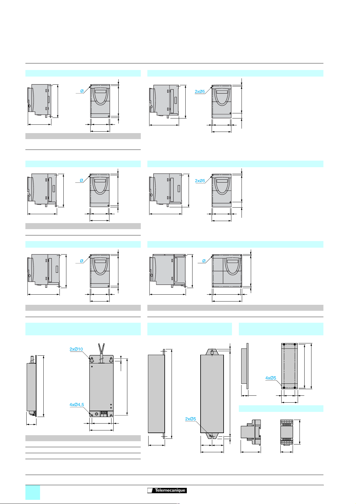
Dimensions
5
Variable speed drives
for asynchronous motors
Altivar 11
ATV 11HU05//E/U/A, ATV 11PU////E/U/A ATV 11HU09M2E
=
2x
b
c
ATV 11 a b c G H Ø
//E/U,
HU05
PU
HU05
PU
////E/U
//A,
////A
72 142 101 60±1 131±1 5
72 142 108 60±1 131±1 5
G
=
a
ATV 11HU09//U/A ATV 11HU12M2E, ATV 11HU18M2E
2x
b
H
=
=
=
H
125
142
60==
72
142
0
12016,5 5,5
12016,5 5,
c
ATV 11 a b c G H Ø
//U 72 142 125 60±1 131±1 5
HU09
//A 72 142 132 60±1 131±1 5
HU09
G
=
a
=
=
138
60==
72
ATV 11HU18M/U/A ATV 11HU18F1U/A, ATV 11HU29M/E/U/A, ATV 11HU41M/E/U/A
=
2x
b
c
ATV 11 a b c G H Ø ATV 11 a b c G H Ø
HU18M
/U 72 147 138 60±1 131±1 5 HU18F1U, HU29M/E/U, HU41M/E/U 117 142 156 106±0,5 131±1 5
/A 72 142 145 60±1 131±1 5 HU18F1A, HU29M/A, HU41M/A 117 142 163 106±0,5 131±1 5
HU18M
G
=
a
H
=
=
c
EMC input filters VW3 A11401 to A11404 Protected braking resistors
VW3 A58732 and A58733
8,5
4x
b
G==
a
H==
Non protected braking resistors VW3
A58702 and A58704
(2-wire output, length 0.5 m)
=
154
170
b
c
VW3 a b c G H
A11401 75 194 30 61 180
A11402 117 184 40 97 170
A11403 75 194 40 61 180
A11404 117 190 40 97 170
Presentation:
pages 2 and3
12
G==
a
Characteristics:
pages 8 to11
H
332
310
30
40 ==
60
Braking module VW3 A11701
(for mounting on AM1-ED rail)
90
61
References:
pages 4 to7
=
85
Schemes:
pages 14 and 15
=
=
73
45
Schneider Electric
Page 12

Dimensions,
mounting
Variable speed drives
for asynchronous motors
Altivar 11
ATV 08 adaptor plate VW3 A11811 Plates for mounting on rail VW3 A11851 and A11852
0
142
32,9 77,5
EMC earthing plate VW3 A11831 Ventilation kit VW3 A11821
(1)
(2)
61
15
(1) 2 screws supplied for fixing the earthing plate.
(2) 5 x Ø 4 mm screws for fixing EMC clamps.
67,6
143,6
37,9 77,5
59,9
23,3 59
143,6
39,9 122,8
Mounting recommendations
# Install the unit vertically, at ± 10°.
# Do not place it close to heating elements.
# Leave sufficient free space to ensure that the air required for cooling purposes can circulate, by natural convection or by ventilation, from the
botto m to the top of the unit.
# Free space in front of unit: 10 mm minimum.
-10 °C to 40 °C
d ³ 50 mm: no special precautions.
d = 0 (mounted side by side): remove the protective cover from the top of the drive
40 °C to 50 °C
d ³ 50 mm: remove the protective cover from the top of the drive
50 °C to 60 °C
d ³ 50 mm: remove the protective cover from the top of the drive, and derate the
nominal current of the drive by 2.2% per °C above 50 °C.
Recommendations for mounting on a machine frame (specific to ATV 11PU///// drives)
ATV 11P////// drives can be mounted on (or in) a steel or aluminium machi ne
(1)
(2)
(1) 2 x Ø M5 tapped holes.
(2) Minimum machined area
Presentation:
pages 2 and 3
Schneider Electric
Characteristics:
pages 8 to11
frame, observing the following conditio ns:
# Maximum ambient temperatur e: 40 °C
# Vertical mounting ± 10°
# The drive must be fixed at the centre of a support (frame) which is a minimum of
10 mm thick and with a minimum cooling area of 0.12 m
aluminium, exposed to the open air.
# Support area for the drive (142 x 72 min) machined on the frame with a surface
smoothness of 100 mm max and an unevenn ess of 3.2 mm max
# Mill the tapped holes lightly in order to remove any burrs.
# Coat the whole drive support area with thermal contact grease (or equivalent).
When the operating conditions are close to the ma ximum limits (power , cycle and
temperature), this type of use must be checked be forehand, by monitoring the
thermal state of the drive .
References:
pages 4 to7
Schemes:
pages 14 and 15
2
for steel and 0.09 m2 for
13
Page 13

Schemes
Variable speed drives
for asynchronous motors
Altivar 11
Schemes with contactor
3-phase power supply ATV 11////M3/ Single phase power supply ATV 11////F1/ and ATV
200…240 V 50/60 Hz
12
34
56
Q1
(4)
12
34
56
KM1
(1) (2) (3)
A1
L3
L1
L2
RA
RC
LI1
LI2
LI3
LI4
DO
+ 15 V
AI1
U
V
W
PA/+PC/
V1
U1
W1
A2
+
M1
3
Braking
resistor
PA
(5)
PB
Potentiometer
speed
reference
+ 5 V
0 V
0 -20 mA
or
4 -20 mA
0-10 V
(external power supply)
11
////M2/
100...120 V 50/60 Hz and 200...240 V 50/60 Hz
12
34
5
Q1
6
12
34
KM1
(1) (2) (3)
A1
L1
N/L2
U
V
V1
U1
M1
3
W
W1
Braking
resistor
A2
RA
PA/+PC/
+
PA
RC
(5)
PB
LI1
LI2
AI1
+ 5 V
Potentiometer
speed
reference
LI3
LI4
0 V
0 -20 mA
or
4 -20 mA
0-10 V
(external power supply)
0
(4)
DO
+ 15 V
2-wire control 3-wire control Analog voltage input Analog current input
External 10 V use 0-20 mA or 4-20 mA
ATV 11 control terminals
LI1
+ 15 V
LI1: Forward
LIx: Reverse
LIx
ATV 11 control terminals
LI1
+ 15 V
LI1: Stop
LI2: Forward
LIx: Reverse
LI2
ATV 11 control terminals
LIx
AI1
Speed
reference
potentiometer
2.2 to 10 kW
0 V
ATV 11 control terminals
AI1
Source
0 -20 mA
or
4 -20 mA
0 V
For combinations of KM1, Q1, etc, components (see the table on page 60251/5).
(1) Fault relay contact: for remo te signalling of drive status.
(2) Internal +15 V. If an external +24 V supply is used, connect the 0 V on th e external supply to the 0 V terminal, do not use the + 15 terminal on the drive, and
connect the common o f the LI inputs to the + 24 V of the external supply.
(3) DO output: can be configured as an analog or a logic output. Internal voltage + 15 V or external + 24 V.
(4) Galvanometer or low level relay.
(5) Braking module VW3 A11701, if braking resistor VW3 A587
//
is used.
Note: Fit interference suppressors to all inductive circuits near the drive or connected on the same circuit, such as relays, contactors, solenoid valves, fluorescent
lighting, etc.
Presentation:
pages 2 and3
14
Characteristics:
pages 8 to11
References:
pages 4 to7
Schemes:
pages 14 and 15
Schneider Electric
Page 14

Connections
Variable speed drives
for asynchronous motors
Altivar 11
Electromagnetic compatibility
Connections to meet the requirements of EMC standards
Principle
# Earths between the drive, the motor and the cable shielding must have "high frequency" equipotentiality.
# Use shielded cables with shielding connected to earth at 360° at both ends for the motor cables, and if necessary the braking module and
resistor and control-signalling cables. Conduit or metal ducting can be used for part of the shielding length provided that there is no break in
continuity.
# Ensure maximum separation between the power supply cable (line supply) and the motor cable.
Installation diagram for ATV 11/U////E/U/A
3
2
4
1
5
1 Earthing plate VW3 A 11831 to be fitted on the drive.
2 Altivar 11
3 Non-shielded power supply cabl e.
4 Non-shielded cable for fault relay contacts output.
5 Fix and earth the shielding of cables 6 and 7 as close as possible to the drive:
- strip the shielding
- use cable clamps of an appro priate size on the part s from which the shielding
has been stripped, to attach them to the earthing plate.
- the shielding must be clamped tightly enough to the earthi ng plate to ensure
good co ntact
- types of clamp: non-oxidizing metal
6 Shielded cable (1) for connecting the motor.
7 Shielded cable (1) for connectin g the control/signalling system. For applicat ions
which require a large number of conductors, small cross-sections must be used
2
(0.5 mm
8 PE ca ble.
(1) The shielding of cables (6, 7 and 8) must be connected to earth at both ends.
The shielding must be continuous and if intermediate terminals are used, they must be in EMC
metal boxes.
).
0
7
8
Note: If using an additional input filter, it must be mounted under the drive and connected directly to the line supply via a non-shielded cable. Link 3 on the drive is
then via the filter output cable.
Although there is an HF equipotential earth connection between the drive, the m otor and the cable shielding, it is still necessary to connect the PE protective
conductors (green-yellow) to the appropriate terminals on ea ch of the devices.
6
Presentation:
pages 2 and 3
Schneider Electric
Characteristics:
pages 8 to11
References:
pages 4to7
Schemes:
pages 14 and 15
15
Page 15

Presentation
510888
502945
PowerSuite advanced dialogue
solutions
The PowerSuite advanced dialogue solutions can be used for Schneider Electric
drives and starters. They enable communication with the product from a Pocket PC,
a PC or a dedicated terminal.
The solutions, with a Pocket PC or PC, enable f iles to be prepared for uploading to
the drives and the starters. The PowerSuite software creates its files ensuring
consistency between the configuration/a djustment functions of the product.
PowerSuite Pocket PC
The Pocket PC can be used during preparation, programming, setup and
maintenance.
It comprises a Pocket PC terminal and corresponding connection accessories.
The sof tw ar e is integra t ed i nt o a Wi nd ow s C E environmen t , fo r whi ch th e op er at i n g
system language can be selected on ordering (English, French, German, Spanish,
Italian).
The software i ncorp orates al l the fu nctions of int egrated an d remote t ermi nals (driv e or
starter configuration and adjustment, control, signalling, etc).
The Pocket PC can be used:
# alone to prepare and store configuration/adjustment files (integral battery or l ine
supply)
# connected to a PC for uploading configuration/adjustment files from the Pocket PC
to the PC or downloading from the PC to the Pocket PC
# connected to the drive or to the starter for configuration, adjustment or control
purposes or to upload a configuration/adjustment file from the Pocket PC to the
product or download a config uration/adjustment file from the product to the Pocket
PC.
510086
PowerSuite software workshop for PC
The PowerSuite software workshop is used to set up a drive or a starter from a PC
in a Microsoft Windows 95, 98, NT4 or 2000 env ironment.
The software incorporates all the functions of integrated and remote terminals (drive
or starter configuration and adjustment, control, signalling, etc.) with assisted, guided
operator dialogue in 5 languages (English, French, G erman, Spanish, Italian) in a
Windows environment.
It can be used:
# alone to prepare and store drive or starter configuration files on diskette, CD-ROM
or hard disk
The drive or starter configuration can be pr inted out on paper or can be exported to
office automation software.
# connected to the drive or starter for configuration, adjustment or control purposes,
or for uploading a configuration/adjustment file from the PC to the product or
downloading from the product to the PC.
Connection is via a link between the drive or starter connector and the serial port on
the PC.
Magelis display unit with matrix screen
The Magelis display unit with matrix screen can be used to monitor, diagnose and
adjust up to 8 Altivar 28, 38, 58 or 58F drives in 5 languages (English, French,
German, Spanish, Italian). It can display variables in alphanumeric format with
European, Cyrillic or Asian fonts in 4 sizes, or it can display icons or background
images in black and white as well as animations in barchart or gauge format. The
application is preloaded in the factory.
Compatibility
Compatibility of advanced dialogue solutions with drives and
starters
PowerSuite Pocket PC
Pocket PC VW3 A8108// 49 49 49 49
Setup kit VW3 A8 102 49 49 49 49
Connection kit VW3 A8111
PowerSuite software workshop for PC
CD-ROM VW3 A8104 1 4 V 1.0 4 V 1.40 49 4 V 1.30 4 V 1.40
Connection kit VW3 A8106
Magelis display unit with matrix screen
Display unit XBT HM017010A8
Accessories
CD-ROM VW3 A8105 1 4 V 1.0 4 V 1.40 49 4 V 1.30 4 V 1.40
Operator terminal VW3 A8103//
Incompatible products Compatible products and versions
1 V 1.40 software version available 2
QG
half 2002.
Drives Starter TeSys model U
ATV 28, ATV 58,
ATV 58F
ATV 38 ATV 11 ATS 4 8
controllerstarters
16
6FKQHLGHU(OHFWULF
Page 16

Reference
PowerSuite advanced dialogue
solutions
520962
VW3 A8103
//
PowerSuite Pocket PC
Several solutions are available to meet the needs of individual users:
- the complete Pocket PC
- the setup kit
- the connection kit for Pocket PC.
The complete Pocket PC comprises:
- 1 "Jordana 525" Pocket PC , with multilingual operating system (1), supplied with
PC synchronisation cable and mains power supply
- 1 CD-ROM containing the multilingual (1) setup software which can be ordered
separately
- 1 connection kit for Pocket PC
The setup kit comprises:
- 1 CD-ROM containing the multilingual (1) setup software which can be ordered
separately
- 1 connection kit for the Pocket PC
The connection kit for the Pocket PC comprises:
- 2 connection cables, length 0.6 m, with 2 RJ45 connectors
- 1 RJ45/9-way SUB-D adaptor for connecting ATV 58 and ATV 58F
- 1 converter marked “RS 232/RS 485 PPC” with one 9-way male SUB-D connector
and 1 RJ45 connector.
FRQYHUWHUIRU$79ZLWKRQHZD\PDOHFRQQHFWRUDQG5-FRQQHFWRU
Description Reference Weight
Complete Pocket PC VW3 A8108// (2) 1.000
Setup kit VW3 A8102 0.400
Connection kit for the Pocket PC VW3 A8111 0.300
kg
PowerSuite software workshop for PC
The PowerSuite software comprises:
- 1 CD-ROM containing the multilingual (1) setup software
- 1 connection kit for PC
The PC connection kit comprises:
- 2 connection cables, length 3 m, with 2 RJ45 connectors
- 1 RJ45/9-way SUB-D adaptor for connection of ATV-58 and ATV-58F drives
- 1 converter marked “RS 232/RS 485 PC” with one 9-way female SUB-D connector
and 1 RJ45 connector
FRQYHUWHUIRU$79ZLWKRQHZD\PDOHFRQQHFWRUDQG5-FRQQHFWRU
Description Reference Weight
1 CD-ROM containing the multilingual setup so ftware (1) VW3 A8104 1 0.100
kg
105080
XBT HM017010A8
Connection kit for PC VW3 A8106 0.350
Magelis display unit with matrix screen
The terminal has a backlit LCD with 8 lines of 40 charac ters.
The RS 458 connection kits for ATV 28 (VW3 A28301), ATV 38 and ATV 58
(VW3 A58306) drives, as w ell as other connection accessories, should be ordered
separately according to the number and type of drives connected. Please consu lt
your Regional Sales Office.
Description Reference Weight
Magelis display unit with matrix screen XBT HM017010A8 0.600
kg
Accessories
Description Reference Weight
1 upgrade CD-ROM for multilingual setup software VW3 A8105 1 0.100
“Jordana 525” Pocket PC terminal supplied with PC
synchronisation cable and mains power supply
[0%FRPSDFWIODVKFDUGFRQWDLQLQJWKH3RFNHW3&
VRIWZDUHIRUWKH-RUQDGD
(1) English, French, German, Spanish, Italian.
(2) To order the operating system in your chosen language, replace
French, DE for German, SP for Spanish and IT for Italian.
(3) To find out about the latest available version, please consult your Regional Sales Office.
(4) This card enables the software to be run immediately without synchronising with a PC.
1 V 1.40 software version available 2
QG
half 2002.
VW3 A8103// (2) 0.300
VW3 A8110 0.100
//
by EN for English, FR for
kg
6FKQHLGHU(OHFWULF
17
Page 17

Functions
Variable speed drives
for asynchronous motors
Altivar 11
Summary of functions
Operating speed range page 60255/3
Acceleration and deceleration ramp times page 60255/3
Second ramp page 60255/3
Deceleration ramp adaptation page 60255/3
Preset speeds page 60255/4
Configuration of analog input AI1 page 60255/4
Analog or logic output DO page 60255/4
Forward/reverse operation page 60255/4
2-wire control page 60255/5
3-wire control page 60255/5
Automatic d.c. injection page 60255/5
Switching frequency, noise reduction page 60255/5
Fault relay, unlocking page 60255/5
Fault reset page 60255/6
Automatic restart page 60255/6
Automatic catching a spinning load with speed detection page 60255/6
Controlled stop on loss of line supply page 60255/6
Drive thermal protection page 60255/6
Motor thermal protection page 60255/6
Monitoring page 60255/7
Incompatible functions page 60255/7
Functions specific to th e Asia ran ge page 60255/7
Drive factory setting
To facilitate the setting up of the drive, the functions have been programmed to the meet the
requirements of the most common applications.
0
Drive functions and I/O :
# 2-wire control on transition
5 Logic input LI1 : forward
5 Logic input LI2 : reverse
# Preset speeds:
5 Logic input LI3 : preset speeds
5 Logic input LI4 : preset speeds
# Analog input AI1 : 0-5 V speed reference
# Logic/analog output DO : motor frequency (analog)
# Dec eleration ramp adap tation
# Automatic d.c. current injection for 0.5 s to standstill.
Functions of the display and the keys
Altivar 11
1
3
ESC
5
RUN
ENT
STOP
4
2
6
7
18
1 Information is displayed in the form of codes or values in three "7-segment"
displays
2 Buttons for scrolling through the menus or modifying values
3 “ESC” : Button for exiting the menus (no confirmation).
4 “ENT” : Validation button for entering a menu or confirming th e new value selected
# Only on the Asia range:
5 “RUN” : Local control of motor operation.
6 “STOP” : Local control of motor stopping.
7 Speed reference potentiometer.
SchneiderElectric
Page 18

Functions (continued)
Variable speed drives
for asynchronous motors
Altivar 11
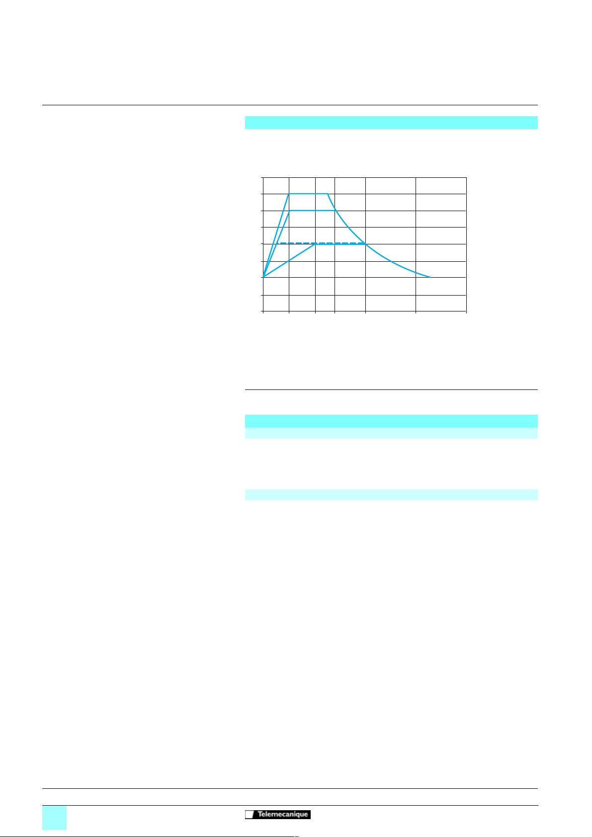
# Operating speed range
Used to determine 2 frequency limits which define the speed range permitted by the machine
under actual operating conditions.
f (Hz)
: low speed, from 0 to HSP, factory setting 0
HSP
LSP
0 V
0 V
0 mA
4 mA
# Acceleration and deceleration ramp times
Used to define acceleration and deceleration ramp times according to the application and the
machine dynamics
f (Hz)
5 V
10 V (external po wer supply)
20 mA
20 mA
LSP
: high speed, from LSP to 200 Hz, factory setting 50/60
HSP
Reference
f (Hz)
0
Adjustment of second ramp with
Pocket PC PowerSuite
50/60
t1
Linear acceleration ramp
Adjustm ent of t1 : 0.1 to 99.9 s
factory setting 3 s.
# Second ramp
Used to switch 2 acceleration or deceleration ramp times, which can be adjusted separately.
Enabled by means of 1 reassignable logic input.
It is suitable for machines with fast continuous speed correction and high speed lathes with
acceleration and deceleration limiting above certain speeds.
f(Hz)
HSP
Forward
or
reverse
1
0
Acc 2
Acc 1
50/60
t0
0t
Linear decelera tion ramp
Adjustment of t2 : 0.1 to 99.9 s
factory setting 3 s.
Dec 2
Dec 1
Acceleration 1 (Acc 1) and
deceleration 1 (Dec 1)
- adjustment 0.1 to 99.9 s
- factory setting 3 s
Acceleration 2 (Acc 2) and
deceleration 2 (Dec 2)
t
- adjustment 0.1 to 99.9 s
- factory setting 5 s
: high speed
HSP
t
t2
:
:
Schneider Electri c
1
LI4 0
Example of switching using logic input LI4
# Deceleration ramp adaptation
Used to automa tical ly incr ease th e dece lerat ion ramp ti me if the init ial set ting is too low w hen th e
load inertia is taken into account. This function prevents the drive locking if there is an
overvoltage on deceleration fault.
If this function is disabled, an appropriate braking module and resistor can be used.
t
19
Page 19
Functions (continued)
f(Hz)
Variable speed drives
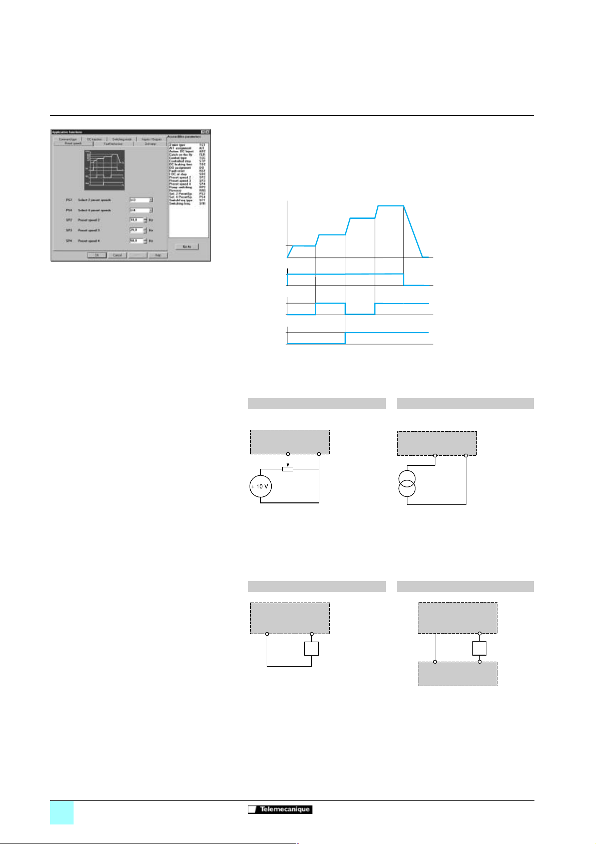
Adjusting the preset speeds with the PowerSuite
software workshop for PC
for asynchronous motors
Alti var 11
# Preset speeds
Used to switch preset speed references.
Choice between 2 or 4 preset speeds.
Enabled via 1 or 2 logic inputs.
The preset speeds can be adjusted in increments of 0.1 Hz from 0 Hz to 200 Hz.
They take priority over the reference given via the analog input or, for the Asia range, on the
drive’s potentiometer.
The spee d ob t a ined with inputs
LIx and LIy at state 0 is LSP or the
speed referenc e, depending on
the leve l of analog input AI 1.
LSP
1
LI1 0
1
LIx 0
1
LIy 0
Example of operation with 4 preset speeds.
# Configuration of analog input AI1
This is used to modify the specifications, for either voltage or current, of analog input AI1.
Factory setting : 0-5 V (internal power supply only).
Other possible values via external power supplies : 0-10 V, 0-20 mA, 4-20 mA.
Analog volt age input Analog current input
External 10 V use 0-20 mA or 4-20 mA use
Factory settings :
st
speed : LSP (low speed or
1
t
reference)
nd
speed : 10 Hz
2
rd
speed : 25 Hz
3
t
th
speed : 50 Hz
4
t
0
Altivar 11 control terminals
AI1
Speed
reference
potentiometer
2.2 to 10 kW
# Analog or logic output DO
Output DO can be programmed to be a logic output or an analog output. It enables remote
signalling of the following information as required :
5 Frequency threshold reached (logic output)
5 Reference reached (logic output)
5 Current threshold reached (logic output)
5 Current in the motor (analog output)
5 Motor frequency (analog output)
0 V
Altivar 11 control terminals
AI1
Supply
0-20 mA
or
4-20 mA
0 V
Diagram with internal power supply Diagram with external power supply
Altivar 11 control terminals
DO
+ 15 V
If it is a lo gic output: Z is a relay or a low level input.
If it is an analog output: Z can be, for example, a galvanometer.
For a ga lv anometer with resi s tance R, the maximum voltage supplied will be :
R W()
Ux
------------------------------------------- R W() 1000 W()+
Altivar 11 control terminals
0 V
DO
0 V
Power supply
+ U
20
# Direction of operation : forward/reverse
In 2-wire control, forward operation cannot be reassigned to any logic input other than LI1.
In 3-wire control, stopping cannot be reassigned to any logic input other than LI1, and forward
operation cannot be reassigned to any logic input other than LI2.
5HYHUVHRSHUDWLRQFDQEHGLVDEOHGIRUDSSOLFDWLRQVwith a single direction of motor rotation, by
not assigning any logic input to reverse operation.
SchneiderElectric
Page 20

Functions (continued)
Variable speed drives
Assignment of logic inputs with
Pocket PC PowerSuite
for asynchronous motors
Altivar 11
# 2-wire control
Used to control the direction of operation by means of a maintained contact.
Run (forward or reverse) and stop are controlled by the same logic input.
Enabled by means of 1 or 2 logic inputs (one or two directions).
This function is suitable for all non-reversing and reversing applications.
3 operating modes are possible :
5 detection of the state of the logic inputs
5 detection of a change in state of the logic inputs
5 detection of the state of the logic inputs with forward operation always having priority over
reverse
Altivar 11 control terminals
LI1
15 V
Wiring diagram for 2-wire control
# 3-wire control
Used to control the operating direction and stopping by means of pulsed contacts.
Run (forward or reverse) and stop are controlled by 2 different logic inputs.
Enabled by means of 2 or 3 logic inputs (non-reversing or reversing).
This function is suitable for all non-reversing and reversing applications.
f (Hz)
LIx
LI1
LIx
: forward
: reverse
0
Adjustment of the "d.c. injection" function using the
PowerSuite software workshop for PC
LI1
LI2
LIx
: Stop
: Forward
: Reverse
t
t
tt
t
0
Stop
1
0
Forward
1
0
1
Reverse
0
Example of operation with 3-wire control
Altivar 11 control terminals
LI1 LI2
15 V
Wiring d iagram fo r 3-wir e control
# Automatic d.c. injection
Enables d.c. injection to standstill, which is adjustable from 0 to 1.2 times the value of the drive
nominal current (preset at 0.7 In), as soon as oper ation is no longer controlled and the motor
speed is zero,
5 either for a period of time, which is adjustable from 0.1 to 30 s (preset at 0.5 s)
5 or continuously.
Factory setting : function active with d.c. injection for 0.5 s.
In 3-wire control, d.c. injection is only active if logic input LI1 is active (stop).
# Switching frequency, noise reduction
High frequency switching of the intermediate d.c. voltage can be used to supply the motor with
a current wave with low harmonic distortion.
There are 3 ranges of switching frequency :
5 Random switching frequency around 2 or 4 kHz (avoids resonance)
5 Fixed low frequen c y adjustable to 2 or 4 kHz
5 Fixed high frequency adjustable to 8, 12 or 16 kHz
Factory setting : Low frequency set at 4 kHz.
This function is suitable for all applications which require low motor noise.
# Fault relay, unlocking
The fault relay is energised when the drive is powered up and is not faulty.
It opens in the event of a fault or when the drive is powered down.
The drive can be unlocked after a fault in one of the following ways :
5 powering down the drive until the display disappears completely, then powering back up
5 activating the logic input associated w ith the “fault reset” function, i f the function is enabled
5 enabling the “automatic restart” function.
LIx
Schneider Electri c
21
Page 21

Functions (continued)
f(Hz)
Variable speed drives
for asynchronous motors
Alti var 11
# Fault reset
Used to clear the stored fault and restart the drive if the cause of the fault has disappeared.
The fault is cleared by a transition of the logic input LI which is assigned to this function.
Factory setting : function inactive.
The restart conditions after a reset to zero are the same as those of a nor mal power-up.
The following faults can be reset : drive thermal overload, motor thermal overload, line supply
overvoltage, over voltage on deceleration, overspeed, line phase loss (1), line supply
undervoltage (2).
# Automatic restart
Enables the drive to be restarted automatically after locking following a fault if this fault has
disappeared and if the other operating conditions permit a restart.
This restart is performed by a series of automatic attempts separated by increasingly longer
waiting periods: 1 s, 5 s, 10 s, then 1 minute for the following periods.
If the drive has not restarted af ter 6 minutes, the drive locks and the procedure is aband on ed
until the drive is powered down and back up again.
Factory setting : function inactive.
Restart autho rised w ith the fo llow ing fau lts : drive thermal ov erload, motor thermal overloa d, lin e
supply overvoltage, overvoltage on deceleration, line phase loss (1), line supply undervoltage
(2).
If the function is enabled, the drive’s safety relay remains activated until one of these faults
appears. This function requires the speed reference and the direction of operation to be
maintained, and is only compatible with 2-wire level control.
This function is suitable for machines or installations in continuous oper ation or without
monitoring, and where a restar t will not endanger equipment or personnel in any way.
# Automatic catching a spinning load with speed detection ("catch on the fly")
Used to restar t the motor smoothly after one of the following events:
5 loss of line supply or power down
5 fault reset or automatic restart
5 “freewheel stop” triggered by a fault.
On restarting, the effective speed of the motor is detected in order to restart on the ramp at this
speed and retur n to the re f er ence s pee d. Th e s peed detec ti on tim e can be up t o 1 s depen di ng
on the initial deviation.
Factory setting : function inactive.
This function requires the activation of 2-wire level control and is not compatible with the
continuous d.c . injection function.
This function is suitable for machines for which the loss of motor speed is negligible during the
line supply loss time (machines with high inertia).
0
Adjustment of the behaviour at a
fault with Pocket PC PowerSuite
Adjusting the thermal protection with the PowerSuite
software workshop for PC
# Controlled stop on loss of line supply
Used to define the drive stopping modes at a "loss of line supply" fault.
Three stopping modes are available for selection :
5 “Freewheel” stop : the drive is locked and the motor stops in accordance with the inertia and
the resistive torque
5 Normal stop : stop with valid deceleration ramp time (deceleration 1 or 2).
5 Fast stop : the stopping time depends on the inertia and the braking ability of the drive.
Factory setting : “Freewheel” stop.
1 Fast stop
2 Normal stop on deceleration ra mp
3 “Fre ewheel” st op
123
# Thermal protection of drive
Direct protection by thermistor, integrated in the drive’s power module. This protects the
components, even in the event of poor ventilation or excessive ambient temperature.
When the fault is detected, it lo cks t he d rive.
# Motor thermal protection
Motor thermal prote ction i s impl emented via co ntinuo us cal culati on of it s theor etical tempe ratur e
rise.
The drive is lock ed on a fault if thi s tempe ra tur e ri se ex ceeds 118% of the nomi nal t emp er atur e
rise.
This function is suitable for applications with self-cooled or force-cooled motors.
Note: The thermal state of the motor is not stored when the drive is powered down.
(1) The line supply phase loss fault is only accessible on drives with 3-phase power supply, if
monitoring of the fault has been enabled (Factory setting : enabled).
(2) The drive will restart as soon as the undervoltage fault disappears, whether or not the function
is active.
t
22
SchneiderElectric
Page 22

Functions (continued)
Variable speed drives
for asynchronous motors
Altivar 11
# Monitoring
The display shows the state of the drive or, if selected, one of the following values:
5 Frequency reference
5 Output frequency applied to the motor
5 Mot or current
5 Line voltage
5 Motor thermal state
5 Driv e thermal s tate
Incompatible functions
The choice of the last funct ion con figur ed is enab led, w hatev er the confi gura tion of t he pr evious
functions.
Application functions can be assigned to the same logic input, in which case one logic input
enables a number of functions (for example : direction of operation and 2nd ramp).
A check must be carried out to ensure that the functions are compatible.
# Direction of operation and 2-wire control : forward operation c an on ly be as si gn ed t o LI1 .
# Direction of operation and 3-wire control : forward operation c an on ly be as si gn ed t o LI2 .
# Automatic restart : requires the configuration of 2-wire level control. Changing the
configuration of the ty pe of control disables automatic restart.
# Automatic catching a spinning load with speed detection :
5 requires the configuration of 2-wire level control. Changing the configuration of the type of
control disables automatic catching a spinning load.
5 not compatible wit h continuous d. c. i nj ec ti on br aki ng to a standstil l . Co nfi gu rin g thi s f un ct io n
disa bles automatic catching a spinning load .
Functions specific to the Asia range
# Local control :
The keypad on the Asia range has 2 additional keys (RUN and STOP) and a potentiometer
(speed reference).
5 The keys and the potentiometer are active if local control is enabled.
The logic and analog inputs are inactive if local control is enabled.
Factory setting : function active.
5 Reverse : if local control is active, the reverse function is not visible.
# Logic inputs :
It is possible to choose the active level of the logic input.
Positive logic : the inputs are active if the signal is ³ 11 V.
Negative logic : the inputs are active if the signal is £ 5 V.
Factory setting : positive logic.
0
Schneider Electri c
23
 Loading...