

Schneider ATV312H055M2, ATV312H037M2, ATV312HU30N4, ATV312HU15N4, ATV312H055N4 User Manual
...
2354235 11/2008
Altivar 312
Variable speed drives
for asynchronous motors
Programming manual
07/2014
BBV46385
www.schneider-electric.com

The information provided in this documentation contains general descriptions and/or technical characteristics of the performance of the products contained herein. This documentation is not intended as a substitute for and is not to be used for determining suitability or reliability of these products for specific user
applications. It is the duty of any such user or integrator to perform the appropriate and complete risk analysis, evaluation, and testing of the products with respect to the relevant specific application or use thereof.
Neither Schneider Electric nor any of its affiliates or subsidiaries shall be responsible or liable for misuse
of the information contained herein. If you have any suggestions for improvements or amendments or have
found errors in this publication, please notify us.
No part of this document may be reproduced in any form or by any means, electronic, or mechanical, including photocopying, without express written permission of Schneider Electric.
All pertinent state, regional, and local safety regulations must be observed when installing and using this
product. For reasons of safety and to help ensure compliance with documented system data, only the
manufacturer should perform repairs to components.
When devices are used for applications with technical safety requirements, the relevant instructions must
be followed.
Failure to use Schneider Electric software or approved software with our hardware products may result in
injury, harm, or improper operating results.
Failure to observe this information can result in injury or equipment damage.
© 2013 Schneider Electric. All rights reserved.
2 BBV46385 01/2014

Contents
Important information __________________________________________________________________________________________ 4
Before you begin______________________________________________________________________________________________ 5
Documentation structure________________________________________________________________________________________ 7
Software enhancements________________________________________________________________________________________ 8
Steps for setting up the drive ____________________________________________________________________________________ 9
Setup - Preliminary Recommendations ___________________________________________________________________________ 10
Factory configuration _________________________________________________________________________________________ 11
Basic functions ______________________________________________________________________________________________ 12
Remote display terminal option, ATV31 ___________________________________________________________________________ 14
Remote graphic display terminal option, ATV61/ATV71_______________________________________________________________ 15
Remote display terminal option, ATV12 ___________________________________________________________________________ 19
Structure of the parameter tables ________________________________________________________________________________ 20
Compatibility of functions ______________________________________________________________________________________ 21
List of functions that can be assigned to inputs/outputs_______________________________________________________________ 23
List of functions that can be assigned to the Network and Modbus control word bits ________________________________________ 25
Checklist ___________________________________________________________________________________________________ 26
Programming _______________________________________________________________________________________________ 27
[SPEED REFERENCE] (rEF-) menu _____________________________________________________________________________ 31
[SETTINGS] (SEt-) menu ______________________________________________________________________________________ 32
[MOTOR CONTROL] (drC-) menu _______________________________________________________________________________ 41
[INPUTS / OUTPUTS CFG] (I-O-) menu __________________________________________________________________________ 47
[COMMAND] (CtL-) menu______________________________________________________________________________________ 50
[COMMAND] (CtL-) menu______________________________________________________________________________________ 61
[APPLICATION FUNCT.] (FUn-) menu ___________________________________________________________________________ 62
[FAULT MANAGEMENT] (FLt-) menu ____________________________________________________________________________ 91
[COMMUNICATION] (COM-) menu ______________________________________________________________________________ 98
[MONITORING] (SUP-) menu _________________________________________________________________________________ 100
Migration ATV31 - ATV312____________________________________________________________________________________ 105
Diagnostics and troubleshooting________________________________________________________________________________ 106
Index of functions ___________________________________________________________________________________________ 111
Index of parameter codes and customer settings___________________________________________________________________ 112
BBV46385 07/2014 3

Important information
The addition of this symbol to a Danger or Warning safety label indicates that an electrical hazard exists, which will result in
personal injury if the instructions are not followed.
This is the safety alert symbol. It is used to alert you to potential personal injury hazards. Obey all safety messages that follow
this symbol to avoid possible injury or death.
NOTICE
Read these instructions carefully, and look at the equipment to become familiar with the device before trying to install, operate, or maintain
it. The following special messages may appear throughout this documentation or on the equipment to warn of potential hazards or to call
attention to information that clarifies or simplifies a procedure.
DANGER
DANGER indicates an imminently hazardous situation which, if not avoided, will result in death, serious injury or
equipment damage.
WARNING
WARNING indicates a potentially hazardous situation which, if not avoided, can result in death, serious injury or
equipment damage.
CAUTION
CAUTION indicates a potentially hazardous situation which, if not avoided, can result in injury or equipment damage.
CAUTION
CAUTION, used without the safety alert symbol, indicates a potentially hazardous situation which, if not avoided, can
result in equipment damage.
PLEASE NOTE
The word "drive" as used in this manual refers to the "controller portion" of the adjustable speed drive as defined by NEC.
Electrical equipment should be installed, operated, serviced, and maintained only by qualified personnel. No responsibility is assumed by
Schneider Electric for any consequences arising out of the use of this documentation.
© 2013 Schneider Electric. All rights reserved.
4 BBV46385 07/2014

Before you begin
Read and understand these instructions before performing any procedure with this drive.
DANGER
HAZARD OF ELECTRIC SHOCK, EXPLOSION, OR ARC FLASH
• Only appropriately trained persons who are familiar with and understand the contents of this manual and all other pertinent product
documentation and who have received safety training to recognize and avoid hazards involved are authorized to work on and with
this drive system. Installation, adjustment, repair and maintenance must be performed by qualified personnel.
• The system integrator is responsible for compliance with all local and national electrical code requirements as well as all other
applicable regulations with respect to grounding of all equipment.
• Many components of the product, including the printed circuit boards, operate with mains voltage. Do not touch. Use only electrically
insulated tools.
• Do not touch unshielded components or terminals with voltage present.
• Motors can generate voltage when the shaft is rotated. Prior to performing any type of work on the drive system, block the motor
shaft to prevent rotation.
• AC voltage can couple voltage to unused conductors in the motor cable. Insulate both ends of unused conductors of the motor cable.
• Do not short across the DC bus terminals or the DC bus capacitors or the braking resistor terminals.
• Before performing work on the drive system:
- Disconnect all power, including external control power that may be present.
- Place a "Do Not Turn On" label on all power switches.
- Lock all power switches in the open position.
- Wait 15 minutes to allow the DC bus capacitors to discharge. The DC bus LED is not an indicator of the absence of DC bus voltage
that can exceed 800 Vdc.
- Measure the voltage on the DC bus between the DC bus terminals using a properly rated voltmeter to verify that the voltage
is < 42 Vdc.
- If the DC bus capacitors do not discharge properly, contact your local Schneider Electric representative.
• Install and close all covers before applying voltage.
Failure to follow these instructions will result in death or serious injury.
DANGER
UNINTENDED EQUIPMENT OPERATION
• Read and understand this manual before installing or operating the Altivar 312 drive.
• Any changes made to the parameter settings must be performed by qualified personnel.
Failure to follow these instructions will result in death or serious injury.
WARNING
DAMAGED EQUIPMENT
Do not install or operate any drive that appears damaged.
Failure to follow these instructions can result in death, serious injury, or equipment damage.
BBV46385 07/2014 5

Before you begin
WARNING
LOSS OF CONTROL
• The designer of any control scheme must consider the potential failure modes of control paths and, for critical control functions, provide
a means to achieve a safe state during and after a path failure. Examples of critical control functions are emergency stop, overtravel
stop, power outage, and restart.
• Separate or redundant control paths must be provided for critical control functions.
• System control paths may include communication links. Consideration must be given to the implications of unanticipated transmission
delays or failures of the link.
• Observe all accident prevention regulations and local safety guidelines.
• Each implementation of the product must be individually and thoroughly tested for proper operation before being placed into service.
Failure to follow these instructions can result in death, serious injury, or equipment damage.
a. For USA: Additional information, refer to NEMA ICS 1.1 (latest edition), “Safety Guidelines for the Application, Installation, and Maintenance of Solid State Control”
and to NEMA ICS 7.1 (latest edition), “Safety Standards for Construction and Guide for Selection, Installation and Operation of Adjustable Speed Drive Systems.”
a
6 BBV46385 07/2014

Documentation structure
The following Altivar 312 technical documents are available on the Schneider Electric website (www.schneider-electric.com).
Installation Manual
This manual describes how to install and connect the drive.
Programming manual
This manual describes the functions and parameters of the drive's terminals and how to use them.
Quick Start
This document describes how to connect and configure the drive so that the motor can be started both quickly and easily for basic
applications. This document is supplied with the drive.
Manuals for Modbus®, CANopen®, etc.
These manuals describe the installation process, the bus or network connections, signaling, diagnostics and the configuration of parameters
specific to communication.
They also describe the communication services of the protocols.
BBV46385 07/2014 7

Software enhancements
Since it was first marketed, the Altivar ATV 312 has been equipped with additional functions. Software version V5.1 IE 50 has now been
updatedto V5.1 IE 54. This documentation relates to version V5.1 IE 54.
The software version appears on the rating plate attached to the side of the drive.
Enhancements made to version V5.1 IE 54 in comparison to V5.1 IE 50
New possible configuration
- Local configuration : By pressing the MODE button during 3 seconds, the drive switches automatically to Local configuration. The
embedded Jog Dial works as a potentiometer (Fr1 = AIV1) and embedded RUN button is activated.
- Remote configuration : This is the factory configuration.
8 BBV46385 07/2014

Steps for setting up the drive
3. Configure:
v The nominal frequency of the motor
[Standard mot. freq] (bFr) page 41
if this is
not 50 Hz,
v The motor parameters in the [MOTOR
CONTROL] (drC-) menu, page 41
, only if
the factory configuration of the drive is
not suitable,
v The application functions in the
[INPUTS / OUTPUTS CFG] (I-O-) menu,
page 47
, the [COMMAND] (CtL-) menu,
page 50
, and the [APPLICATION
FUNCT.] (FUn-) menu, page 62
, only if
the factory configuration of the drive
is not suitable.
4. In the [SETTINGS] (SEt-) menu,
adjust the following
parameters:
v [Acceleration] (ACC), page 32 and
[Deceleration], (dEC) page 32
,
v [Low speed] (LSP), page 33 and [High
speed] (HSP), page 33
,
v [Mot. therm. current] (ItH), page 33.
2. Apply input power to the drive, but do not
give a run command.
Tips:
• Before beginning programming, complete the customer
setting tables, page
112.
• Use the [Restore config.] (FCS) parameter, page 46,
to return to the factory settings at any time.
• To locate the description of a function quickly, use the index
of functions on page
111.
• Before configuring a function, read carefully the "Function
compatibility" section on pages
21 and 22.
• Note:
The following operations must be performed for optimum
drive performance in terms of accuracy and response time:
- Enter the values indicated on the (motor) rating plate in
the
[MOTOR CONTROL] (drC-) menu, page 41.
- Perform auto-tuning with the motor cold and connected
using the
[Auto-tuning] (tun) parameter, page 43.
- Adjust the [FreqLoopGain] (FLG) parameter, page 33
and the
[Fr.Loop.Stab] (StA) parameter, page 34.
INSTALLATION
1. Please refer to the Installation Manual.
PROGRAMMING
5. Start the drive.
BBV46385 07/2014 9

Setup - Preliminary Recommendations
Before powering up the drive
DANGER
UNINTENDED EQUIPMENT OPERATION
Make sure that all logic inputs are inactive to avoid any unintended operation.
Failure to follow these instructions will result in death or serious injury.
Before configuring the drive
DANGER
UNINTENDED EQUIPMENT OPERATION
• Read and understand this manual before installing or operating the ATV312 drive.
• Any changes made to the parameter settings must be performed by qualified personnel.
• Make sure that all logic inputs are inactive to avoid any unintended operation when parameters are being changed.
Failure to follow these instructions will result in death or serious injury.
Start-up
Note: When factory settings apply and during power-up/manual reset or after a stop command, the motor can only be powered once the
"forward", "reverse" and "DC injection stop" commands have been reset. If they have not been reset, the drive will display [Freewheel stop]
(nSt) but will not start. If the automatic restart function has been configured ([Automatic restart] (Atr) parameter in the [FAULT
MANAGEMENT] (FLt-) menu, page 91
), these commands are taken into account without a reset (to zero) being necessary.
Line contactor
CAUTION
RISK OF DAMAGE TO DRIVE
• Frequent use of the contactor will cause premature ageing of the filter capacitors.
• Do not have cycle times less than 60 seconds.
Failure to follow these instructions can result in equipment damage.
Using a motor with a lower rating or dispensing with a motor altogether
• With the factory settings, motor output phase loss detection is active ([Output Phase Loss] (OPL) = [YES] (YES), page 94). To avoid
having to use a motor with the same rating as the drive when testing the drive or during a maintenance phase, deactivate motor output
phase loss detection ([Output Phase Loss] (OPL) = [No] (nO)). This can prove particularly useful if very powerful drives are being
used.
•Set the [U/F mot 1 selected] (UFt) parameter, page 44,
on [Cst. torque] (L) in the [MOTOR CONTROL] (drC-) menu.
CAUTION
RISK OF DAMAGE TO MOTOR
Motor thermal protection will not be provided by the drive if the motor 's nominal current is 20% lower than that of the drive. Find an
alternative source of thermal protection.
Failure to follow these instructions can result in equipment damage.
10 BBV46385 07/2014

Factory configuration
Factory settings
The Altivar 312 is factory-set for the most common operating conditions:
• Display: drive ready [Ready] (rdY) with motor stopped, and motor frequency with motor running.
• The LI5 and LI6 and logic inputs, AI3 analog input, AOC analog output, and R2 relay are unaffected.
• Stop mode when fault detected: freewheel
Code Description Value Page
bFr [Standard mot. freq] [50Hz IEC] 41
tCC [2/3 wire control] [2 wire] (2C): 2-wire control 30
UFt [U/F mot 1 selected] [SVC] (n): Sensorless flux vector control for constant torque applications 44
ACC
DEC
LSP [Low speed] 0 Hz 33
HSP [High speed] 50 Hz 33
ItH [Mot. therm. current] Nominal motor current (value depending on drive rating) 33
SdC1 [Auto DC inj. level 1] 0.7 x nominal drive current, for 0.5 seconds 35
SFr [Switching freq.] 4 kHz 40
rrS [Reverse assign.] [LI2] (LI2): Logic input LI2 48
PS2 [2 preset speeds] [LI3] (LI3): Logic input LI3 72
PS4 [4 preset speeds] [LI4] (LI4): Logic input LI4 72
Fr1 [Ref.1 channel] [AI1] (AI1) - Analog input AI1 29
SA2 [Summing ref. 2] [AI2] (AI2) - Analog input AI2 70
r1 [R1 Assignment]
brA [Dec ramp adapt.] [Yes] (YES): Function active (automatic adaptation of deceleration ramp) 64
Atr [Automatic restart] [No] (nO): Function inactive 91
Stt [Type of stop] [Ramp stop] (rMP): On ramp 65
CFG [Macro configuration] [Factory set.] (Std) (1) 45
[Acceleration]
[Deceleration]
3.00 seconds 63
[No drive flt] (FLt): The contact opens when a fault is detected or when the drive has
been switched off
49
Check whether the values above are compatible with the application. If necessary, the drive can be used without changing the settings.
(1)If you want to keep the drive's presettings to a minimum, select the macro configuration [Macro configuration] (CFG) = [Start/stop] (StS)
followed by [Restore config.] (FCS) = [Factory Set.] (InI) (page 46
The [Start/stop] (StS) macro configuration is the same as the factory configuration, apart from the I/O assignment:
• Logic inputs:
- LI1, LI2 (reversing): 2-wire transition detection control, LI1 = run forward, LI2 = run reverse.
- LI3 to LI6: Inactive (not assigned).
• Analog inputs:
- AI1: Speed reference 0-10 V.
- AI2, AI3: Inactive (not assigned).
• Relay R1: The contact opens in the event of a detected fault (or drive off).
• Relay R2: Inactive (not assigned).
• Analog output AOC: 0-20 mA, inactive (not assigned).
).
BBV46385 07/2014 11
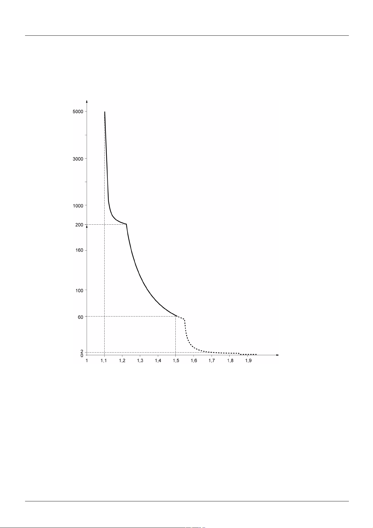
Basic functions
Time
(seconds)
Motor current/In drive
Drive thermal protection
Functions:
Thermal protection by PTC probe fitted on the heatsink or integrated in the power module.
Indirect protection of the drive against overloads by tripping in the event of an overcurrent. Typical tripping values:
- Motor current = 185% of nominal drive current: 2 seconds
- Motor current = 150% of nominal drive current: 60 seconds
Drive ventilation
The fan starts up when the drive is powered up then shuts down after 10 seconds if a run command has not been received.
The fan is powered automatically when the drive is unlocked (direction of operation + reference). It is powered down a few seconds after
the drive is locked (motor speed < 0.2 Hz and injection braking completed).
12 BBV46385 07/2014

Basic functions
Tripping time t
in seconds
Motor current / [Mot. therm. current] (ItH)
Motor thermal protection
Function:
Thermal protection by calculating the I2t.
The protection takes account of self-cooled motors.
CAUTION
RISK OF DAMAGE TO MOTOR
External protection against overloads is required under the following circumstances:
• When the product is being switched on again, as there is no memory to record the motor thermal state
• When supplying more than one motor
• When supplying motors with ratings less than 0.2 times the nominal drive current
• When using motor switching
Failure to follow these instructions can result in equipment damage.
BBV46385 07/2014 13
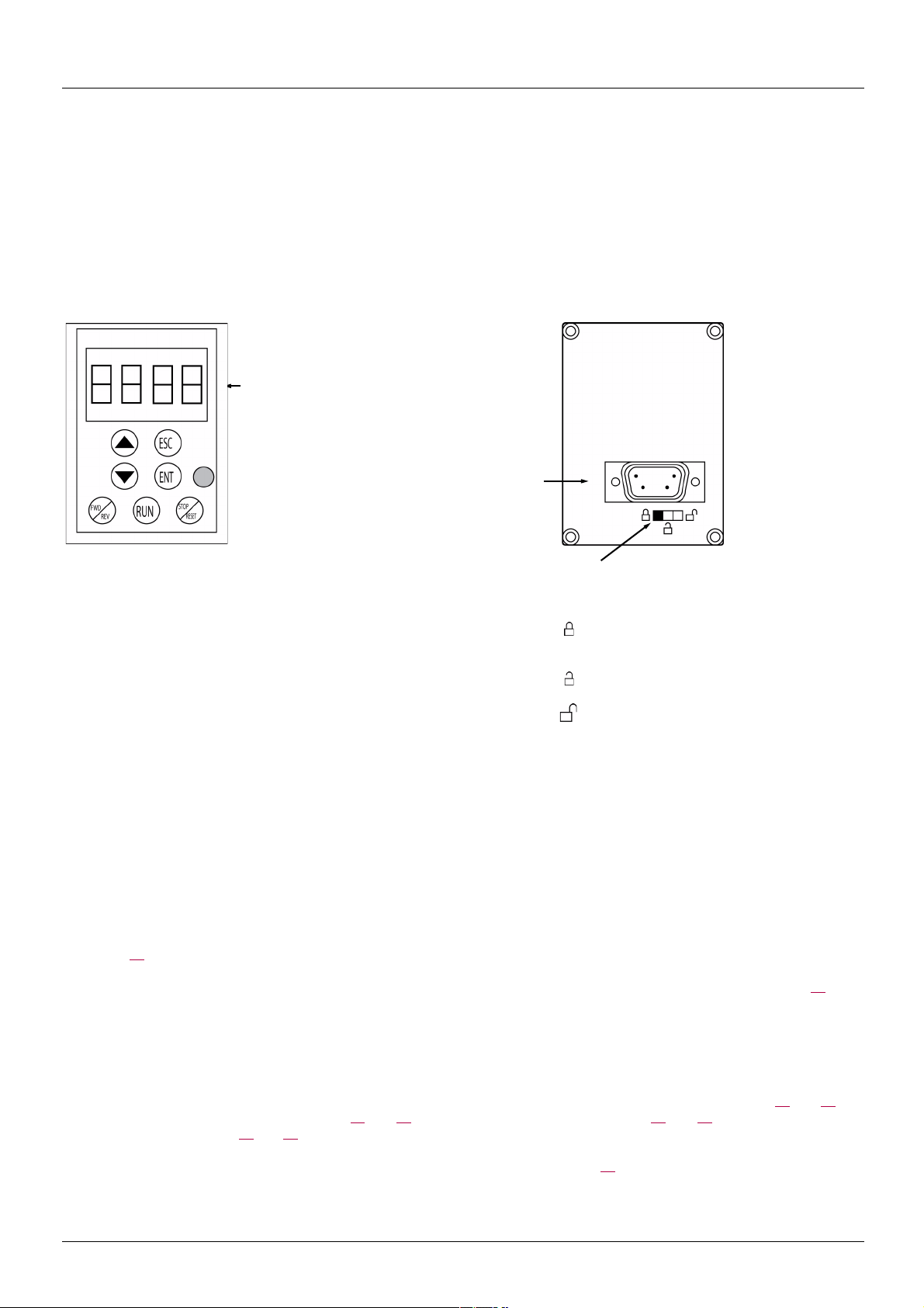
Remote display terminal option, ATV31
4-character
display
Connector
Access locking switch:
• Position:
[MONITORING] (SUP-) and [SPEED
REFERENCE] (rEF-) menus can be
accessed.
[SETTINGS] (SEt-), [MONITORING]
(SUP-) and [SPEED REFERENCE]
(rEF-) can be accessed.
• Position:
• Position: All menus can be accessed
This terminal is a local control unit which can be mounted on the door of the wall-mounted or floor-standing enclosure. It has a cable with
connectors, which is connected to the drive serial link (see the manual supplied with the terminal). Its display capabilities are practically
identical to those of the Altivar 312. With this terminal, however, up and down arrows are used for navigation rather than a jog dial. There
is also an access locking switch for the menus. There are three buttons for controlling the drive (1):
• FWD/REV: Reversal of the direction of rotation
• RUN: Motor run command
• STOP/RESET: Motor stop command or reset
Pressing the button a first time stops the motor, and if DC injection standstill braking is configured, pressing it a second time stops this
braking.
View of the front panel:: View of the rear panel :
Note: Protection via customer confidential code has priority over the switch.
Note:
• The remote terminal access locking switch also locks access by the drive keys.
• When the remote display terminal is disconnected, any locking remains active for the drive keys.
• The remote display terminal will only be active if the [Modbus baud rate] (tbr) parameter in the [COMMUNICATION] (COM-) menu,
page 98
(1)To activate the buttons on the remote display terminal, you first have to configure [HMI command] (LCC) = [Yes] (YES), page 61
, still has its factory setting: [19.2 Kbps] (19.2).
Saving and loading configurations
Up to four complete configurations for ATV312 drives without an option card can be stored on the remote display terminal. These
configurations can be saved, transported and transferred from one drive to another of the same rating. 4 different operations for the same
device can also be stored on the terminal.
See the [Saving config.] (SCS) and [Restore config.] (FCS) parameters in the [MOTOR CONTROL] (drC-) menu, pages 45
[INPUTS / OUTPUTS CFG] (I-O-) menu, pages 49
FUNCT.] (FUn-) menu, pages 90
To transfer a configuration between an ATV31 and an ATV32, follow the procedure on page 90
14 BBV46385 07/2014
and 90.
.
and 46, the
and 49, the [COMMAND] (CtL-) menu, pages 61 and 61, and the [APPLICATION
.

Remote graphic display terminal option, ATV61/ATV71
1 Graphic display
2 Function keys:
F1: CODE
F2, F3: not used
F4: MODE
3 Button to stop/reset
4 Run button
5 Navigation button:
• Press (ENT): - To save the current value
- To enter the selected menu or parameter
• Turn CW/CCW: - To increase or decrease a value
- To go to the next or previous line
- To increase or decrease the reference if control via
the display terminal is activated
7
ESC button:cancels a value, a
parameter or a menu to return
to the previous selection
6
Button for reversing the direction
of rotation of the motor
Description of the terminal
Thanks to the screen size of this graphic display terminal, which works with FLASH V1.1IE19 or higher and is part of the ATV71, it is possible
to display more detailed information than can be shown on an on-board display. It is connected in the same way as the ATV31 remote
display terminal.
Note: Keys 3, 4, 5 and 6 can be used to control the drive directly, if control via the terminal is activated.
To activate the buttons on the remote display terminal, you first have to configure [HMI command] (LCC) = [Yes] (YES), page 61
BBV46385 07/2014 15
.

Remote graphic display terminal option, ATV61/ATV71 (continued)
LANGUAGE
English
Français
Deutsch
Espanol
Italiano
Chinese
Russian
Turkish
ATV312HU15M2
1.5kW/2HP 200V Single
MAIN MENU
DRIVE MENU
LANGUAGE
DRIVE MENU
SPEED REFERENCE
SETTINGS
MOTOR CONTROL
INPUTS / OUTPUTS CFG
COMMAND
Code Mode
APPLICATION FUNCT.
FAULT MANAGEMENT
COMMUNICATION
Powering up the graphic display terminal for the first time
When powering up the graphic display terminal for the first time, the user has to select the required language.
Display after the graphic display terminal has been
powered up for the first time.
Select the language and press ENT.
The drive's rating details will now appear.
3 seconds
or ENT
The [MAIN MENU]
follows automatically.
Automatically switches to the [DRIVE MENU]
menu after 3 seconds.
Select the menu and press ENT.
16 BBV46385 07/2014

Remote graphic display terminal option, ATV61/ATV71 (continued)
ATV312HU15M2
1.5kW/2HP 200V Single
MAIN MENU
DRIVE MENU
LANGUAGE
DRIVE MENU
Standard mot. freq
2/3 wire control
Ref.1 channel
SPEED REFERENCE
SETTINGS
MOTOR CONTROL
INPUTS / OUTPUTS CFG
COMMAND
APPLICATION FUNCT.
FAULT MANAGEMENT
COMMUNICATION
DRIVE MENU
Ready
Code Mode
Powering up the drive for the first time
When powering up the drive for the first time, the user immediately accesses the 3 parameters below: [Standard mot. freq] (bFr), [Ref.1
channel] (Fr1), and [2/3 wire control] (tCC), page 30
. .
Display after the drive has been powered up for the
first time.
The [MAIN MENU]
follows automatically.
3 seconds
ESC
Automatically switches to the [DRIVE MENU]
menu after 3 seconds.
Select the menu and press ENT.
The word "Ready" appears on the graphic display
terminal if you press the ESC key when in the
[DRIVE MENU].
BBV46385 07/2014 17

Remote graphic display terminal option, ATV61/ATV71 (continued)
ATV312HU15M2
1.5kW/2HP 200V Single
MAIN MENU
DRIVE MENU
LANGUAGE
DRIVE MENU
SPEED REFERENCE
SETTINGS
MOTOR CONTROL
INPUTS / OUTPUTS CFG
COMMAND
Code Mode
APPLICATION FUNCT.
FAULT MANAGEMENT
COMMUNICATION
DRIVE MENU
Ready
Code Mode
Subsequent power-ups
Display after powering up.
The [MAIN MENU]
follows automatically.
3 seconds
ESC
Automatically switches to the [DRIVE MENU]
menu after 3 seconds.
Select the menu and press ENT.
The word "Ready" appears on the graphic display
terminal if you press the ESC key when in the
[DRIVE MENU].
18 BBV46385 07/2014

Remote display terminal option, ATV12
1 Graphic display
2 MODE button (1): If [SPEED
REFERENCE] (rEF-) is displayed,
this will take you to the
[SETTINGS] (SEt-) menu. If not, it
will take you to the [SPEED
REFERENCE] (rEF-) menu.
3 ESC button
Used to quit a menu/parameter or
remove the currently displayed
value in order to revert
to the previous value
retained in the memory
4 RUN button
Executes the function
assuming it has been
configured
5 Navigation keys
6 ENT button
Used to save the current value or
access the selected menu/parameter
8 Button for reversing the direction
of rotation of the motor
7 STOP button
Used to stop the motor and
perform a reset
Description of the terminal
This terminal is a local control unit which can be mounted on the door of the wall-mounted or floor-standing enclosure. It has a cable with
connectors, which is connected to the drive serial link (see the manual supplied with the terminal). Its display capabilities are practically
identical to those of the Altivar 312. With this terminal, up and down arrows are used for navigation rather than a jog dial.
(1) If the drive is locked by a code ([PIN code 1] (COd), page 103
(SUP-) menu to the [SPEED REFERENCE] (rEF-) menu and vice versa.
To activate the buttons on the remote display terminal, you first have to configure [HMI command] (LCC) = [Yes] (YES), page 61
), pressing the Mode key enables you to switch from the [MONITORING]
.
BBV46385 07/2014 19

Structure of the parameter tables
APPLICATION FUNCT.] menu (Fun-)
Code Name/Description Adjustment
range
Factory
setting
PI-
b [PI regulator]
Note: The "PI regulator" function is incompatible with several functions (see page 21). It can only
be configured if these functions are unassigned, in particular the summing inputs (set [Summing
ref. 2] (SA2) to [No] (nO), page 70
) and the preset speeds (set [2 preset speeds] (PS2) and
[4 preset speeds] (PS4) to [No] (nO), page 72
) which will have been assigned as part of the
factory settings.
PIF
M [PID feedback ass.]
[Non] (nO)
no
AI1
A12
A13
v [Non] (nO): not assigned
v [AI1] (AI1): analog input AI1
v [AI2] (AI2): analog input AI2
v [AI3] (AI3): analog input AI3
5
2
3
1
4
6
8
7
1. Name of menu on 4-digit 7-segment display
2. Submenu code on 4-digit 7-segment display
3. Parameter code on 4-digit 7-segment display
4. Parameter value on 4-digit 7-segment display
5. Name of menu on ATV61/ATV71 graphic display terminal
6. Name of submenu on ATV61/ATV71 graphic display terminal
7. Name of parameter on ATV61/ATV71 graphic display terminal
8. Value of parameter on ATV61/ATV71 graphic display terminal
The parameter tables contained in the descriptions of the various menus are organized as follows.
Example :
20 BBV46385 07/2014

Compatibility of functions
Incompatible functions
The following functions will be inaccessible or deactivated in the cases described below:
Automatic restart
This is only possible for the 2-wire level control type ([2/3 wire control] (tCC) = [2 wire] (2C) and [2 wire type] (tCt) = [Level] (LEL) or
[Fwd priority] (PFO)).
Catch on the fly
This is only possible for the 2-wire level control type ([2/3 wire control] (tCC) = [2 wire] (2C) and [2 wire type] (tCt) = [Level] (LEL) or
[Fwd priority] (PFO)).
This function is locked if automatic standstill injection has been configured as DC ([Auto DC injection] (AdC) = [Continuous] (Ct)).
Function compatibility table
The choice of application functions may be limited by the number of I/O and by the fact that some functions are incompatible with one
another. Functions which are not listed in this table are compatible.
If there is an incompatibility between functions, the first function configured will prevent the others being configured.
To configure a function, first check that functions which are incompatible with it are unassigned, especially those which are
assigned in the factory settings.
Summing inputs (factory setting)
+/- speed (1)
Management of limit switches
Preset speeds (factory setting)
PI regulator
Jog operation
Brake control
DC injection stop
Summing inputs (factory setting)
+/- speed (1)
Management of limit switches
Preset speeds (factory setting)
PI regulator
Jog operation
Brake control
DC injection stop
Fast stop
Freewheel stop
(1)Excluding special application with reference channel [Ref.2 channel] (Fr2) (see diagrams 53
p
Incompatible functions Compatible functions Not applicable
Priority functions (functions which cannot be active at the same time):
XA
Stop functions take priority over run commands.
Speed references via logic command take priority over analog references.
The function marked with the arrow takes priority over the other.
pApA
p ppp
p
Xp pA
pppp pp
Xp Xp p
pp p
p A
XX
Fast stop
and 55)
Freewheel stop
A
BBV46385 07/2014 21

Compatibility of functions
Logic and analog input application functions
Each of the functions on the following pages can be assigned to one of the inputs.
A single input can activate several functions at the same time (reverse and 2nd ramp for example). The user must therefore ensure that
these functions can be used at the same time.
The [MONITORING] (SUP-) menu ([[LOGIC INPUT CONF.]] (LIA-) parameter, page 104
parameter, page 104
Before assigning a reference, command or function to a logic or analog input, the user must check that this input has not already been
assigned in the factory settings and that no other input has been assigned to an incompatible or unwanted function.
• Example of incompatible function to be unassigned:
In order to use the "+speed/-speed" function, the preset speeds and summing input 2 must first be unassigned.
The table below lists the factory-set input assignments and the procedure for unassigning them.
Assigned input Function Code To unassign, set to: Page
LI2 Run reverse rrS nO 48
LI3 2 preset speeds PS2 nO 72
LI4 4 preset speeds PS4 nO 72
AI1 Reference 1 Fr1 Anything but AI1 58
LI1 Run forward tCC 2C or 3C 47
AI2 Summing input 2 SA2 nO 70
) can be used to display the functions assigned to each input in order to check their compatibility.
, and [[ANALOG INPUTS IMAGE]] (AIA-)
22 BBV46385 07/2014

List of functions that can be assigned to inputs/outputs
Logic inputs Page Code Factory setting
Not assigned - - LI5 - LI6
Run forward - - LI1
2 preset speeds 72
4 preset speeds 72
8 preset speeds 72
16 preset speeds 73
2 preset PI references 80
4 preset PI references 81 Pr4
+ speed 77
- speed 77
Jog operation 75 JOG
Ramp switching 64
2nd current limit switching 86
Fast stop via logic input 65 FSt
DC injection via logic input 66
Freewheel stop via logic input 67
Run reverse 48
External fault 93
RESET 92
Forced local mode 99
Reference switching 59
Control channel switching 60
Motor switching 87
Forward limit switch 89
Reverse limit switch 89
Fault inhibition 96
PS2 LI3
PS4 LI4
PS8
PS16
Pr2
USP
dSP
rPS
LC2
dCI
nSt
rrS LI2
EtF
rSF
FLO
rFC
CCS
CHP
LAF
LAr
InH
Analog inputs Page Code Factory setting
Not assigned - - AI3
Reference 1 58
Reference 2 58
Summing input 2 70
Summing input 3 70
PI regulator feedback 80
BBV46385 07/2014 23
Fr1 AI1
Fr2
SA2 AI2
SA3
PIF

List of functions that can be assigned to inputs/outputs
Analog/logic output Page Code Factory setting
Not assigned - - AOC/AOV
Motor current 48
Motor frequency 48
Motor torque 48
Power supplied by the drive 48
Drive detected fault (logic data) 48
Drive running (logic data) 48
Frequency threshold reached (logic data) 48 FtA
High speed (HSP) reached (logic data) 48
Current threshold reached (logic data) 48
Frequency reference reached (logic data) 48 SrA
Motor thermal threshold reached (logic data) 48
Brake sequence (logic data) 48
OCr
OFr
Otr
OPr
FLt
rUn
FLA
CtA
tSA
bLC
Relay Page Code Factory setting
Not assigned - - R2
Detected fault 49
Drive running 49
Frequency threshold reached 49
High speed (HSP) reached 49
Current threshold reached 49
Frequency reference reached 49
Motor thermal threshold reached 49
Brake sequence 49
Copy of the logic input 49
FLt R1
rUn
FtA
FLA
CtA
SrA
tSA
bLC
LI1 to LI6
24 BBV46385 07/2014

List of functions that can be assigned to the Network and Modbus control word bits
Bits 11 to 15 of the control word Page Code
2 preset speeds 72
4 preset speeds 72
8 preset speeds 72
16 preset speeds 73
2 preset PI references 80
4 preset PI references 81
Ramp switching 64
2nd current limit switching 86 LC2
Fast stop via logic input 65
DC injection 66
External fault 93 EtF
Reference switching 59
Control channel switching 60
Motor switching 87 CHP
PS2
PS4
PS8
PS16
Pr2
Pr4
rPS
FSt
dCI
rFC
CCS
BBV46385 07/2014 25

Checklist
Carefully read the information contained in the programming, installation and simplified manuals, as well as the information in the catalog.
Before starting to use the drive, please check the following points relating to mechanical and electrical installations.
For the full range of documentation, please visit www.schneider-electric.com.
1. Mechanical installation (see the simplified and installation manuals)
• For details of the different installation types and recommendations concerning ambient temperature, please refer to the installation
instructions in the simplified or installation manuals.
• Install the drive vertically in accordance with the specifications. Please refer to the installation instructions in the simplified or
installation manuals.
• When using the drive, both the environmental conditions defined under standard 60721-3-3 and the levels defined in the catalog must
be respected.
• Install the required options for your application. Refer to the catalog for details.
2. Electrical installation (see the simplified and installation manuals)
• Ground the drive. See the sections on how to ground equipment in the simplified and installation manuals.
• Make sure the input supply voltage matches the nominal drive voltage and connect the line supply in accordance with the simplified
and installation manuals.
• Make sure you use appropriate input line fuses and circuit breakers. See the simplified and installation manuals.
• Arrange the cables for the control terminals as required (see the simplified and installation manuals). Separate the supply and control
cables in accordance with EMC compatibility rules.
• The ATV312ppppM2 and ATV312ppppN4 ranges include an EMC filter Using an IT jumper helps reduce leakage current. This is
explained in the paragraph about the internal EMC filter on the ATV312ppppM2 and the ATV312ppppN4 in the installation manual.
• Make sure the motor connections are right for the voltage (star, delta).
3. Using and starting up the drive
• Start the drive. [Standard mot. freq] (bFr), page 29, is displayed the first time the drive is powered up. Make sure the frequency defined
by frequency bFr (the factory setting is 50 Hz) matches the motor's frequency.
• When the drive is powered up for the first time, the [Ref.1 channel] (Fr1) parameter, page 29
parameter, page 30
the drive locally.
• When the drive is powered up subsequently, [Ready] (rdY) is displayed on the HMI.
•The [Restore config.] (FCS) function, page 46
, are displayed after [Standard mot. freq] (bFr). These parameters will need to be adjusted if you wish to control
, is used to reinitialize the drive with the factory settings.
, and the [2/3 wire control] (tCC)
26 BBV46385 07/2014

Programming
• 4 x 7 segment display
RUN button: Controls powering up of the
motor for forward running in LOCAL
configuration and in REMOTE configuration
if the [2/3 wire control] (tCC) parameter in the
[INPUTS /OUTPUTS CFG] (I-O-) menu is set
to [Local] (LOC), page 47
(could be
hidden by door if function disabled)
• Jog dial - can be used for
navigation by turning it clockwise
or counter-clockwise - pressing
the jog dial enables the user to
make a selection or confirm
information.
• Used to quit a menu or parameter
or to clear the value displayed in
order to revert to the value in the
memory
• In LOCAL configuration, 2s
press on ESC button switches
between the control/
programming modes
STOP/RESET button
• Enables detected fault to be reset
• Can be used to control motor stopping
-If [2/3 wire control] (tCC) is not set to
[Local] (LOC), freewheel stop
-If [2/3 wire control] (tCC) is set to [Local]
(LOC), stop on ramp or freewheel stop
during DC injection braking
• 2 CANopen status LEDs
• MON LED, illuminated if
[MONITORING] (SUP-)
menu is active
• CONF LED, illuminated if the
[SETTINGS] (SEt-),
[MOTOR CONTROL]
(drC-),[INPUTS / OUTPUTS
CFG] (I-O-), [COMMAND]
(CtL-), [APPLICATION
FUNCT] (FUn-), [FAULT
MANAGEMENT] (FLt-)
or [COMMUNICATION]
(COM-) menus are active
Functions as a potentiometer in
LOCAL configuration and in REMOTE
configuration if [Ref.1 channel] (Fr1-)
in the [COMMAND] (CtL-) menu is set
to [Image input AIV1] (AIV1)
MODE button (1): 3s press on
MODE button switches between the
REMOTE/LOCAL configurations.
If [SPEED REFERENCE] (rEF-) is
displayed, this will take you to the
[SETTINGS] (SEt-) menu. If not, it
will take you to the [SPEED
REFERENCE] (rEF-) menu.
• Load LED
• REF LED, illuminated if
[SPEED REFERENCE]
(rEF-) menu is active
Note1: In LOCAL configuration, the three Leds REF, MON,and CONF are blinking simultaneously in programming mode and are working
as a Led chaser in control mode.
Description of the HMI
Functions of the display and the keys
Normal display, with no fault code displayed and no startup:
- : Displays the parameter selected in the [MONITORING] (SUP-) menu (default: motor frequency).
If the current is limited, the display flashes. In such cases, CLI will appear at the top left if an ATV61/ATV71 graphic display
terminal is connected to the drive.
- InIt: Initialization sequence
- rdY: Drive ready
- dCb: DC injection braking in progress
- nSt: Freewheel stop
- FSt: Fast stop
- tUn : Auto-tuning in progress
In the event of a detected fault, the display will flash to notify the user accordingly. If an ATV61/ATV71 graphic display terminal is
connected, the name of the detected fault will be displayed.
(1) If the drive is locked by a code ([PIN code 1] (COd), page 103
(SUP-) menu to the [SPEED REFERENCE] (rEF-) menu and vice versa. It is no longer possible to switch between LOCAL and REMOTE
configurations.
), pressing the Mode key enables you to switch from the [MONITORING]
BBV46385 07/2014 27
Programming
bFr
Fr1
tCC
I-O-
CtL-
FUn-
FLt-
COM-
SUP-
SEt-
drC-
rEF-
LOC
35.
rdY
rEN
3s
MODE
MODE
3s
MODE
2s
ESC
rdY
[SPEED REFERENCE]
[SETTINGS]
[MOTOR CONTROL]
[INPUTS / OUTPUTS CFG]
[APPLICATION FUNCT.]
[COMMAND]
[FAULT MANAGEMENT]
[COMMUNICATION]
[MONITORING]
ESC ENT
[Output frequency] (Hz)
= ENT
= - +
SEt- ACC
dEC
26.
26.
15.
= ENT
SFr
ESC
ESC
ENT ENT
ENT
ESC
Parameter selection
These 3 parameters are
only visible at first power up
of the drive.
Settings can be changed
subsequently in menu:
drC- for bFr
CtL- for Fr1
I-O- for tCC.
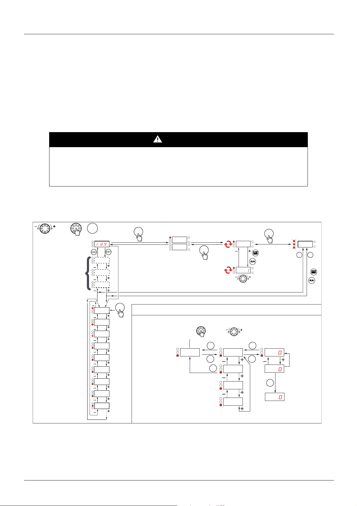
Easy REMOTE and LOCAL configuration
The LOCAL configuration allows to activate automatically the embedded RUN button and the jog dial as a potentiometer.
In that configuration, the speed adjustment will also be effective on remote keypads. MODE button on ATV12 remote display terminal and
on ATV61/71 graphic display terminal (function key F4) is also active to switch from one configuration to another.
[Ref.1 channel] (Fr1) is set to [AI Virtual 1] (AIV1) and [2/3 wire control] (tCC) are set to [Local] (LOC) when switching to LOCAL
configuration.
Choose the configuration (REMOTE or LOCAL) before starting the parameters adjustment of the drive.
For parameters interdependencies reasons, switching from one configuration to another will change other parameters (for example : Input/
Output assignment will return to their factory value).
DANGER
UNINTENDED EQUIPMENT OPERATION
When switching from REMOTE to LOCAL configuration, all the assignments involving the logic inputs will revert to
their default values.
• Check that this change is compatible with the wiring diagram used.
Failure to follow these instructions will result in death or serious injury.
Structure of the menus
28 BBV46385 07/2014

Programming
Configuring the [Standard mot. freq] (bFr), [2/3 wire control] (tCC), and
[Ref.1 channel] (Fr1) parameters
These parameters can only be modified when the drive is stopped and no run command is present.
Code Description Adjustment
range
bFr
50
60
Fr1
AI1
AI2
AI3
AIU1
UPdt
UPdH
LCC
Mdb
nEt
M [Standard mot. freq]
This parameter is only visible the first time the drive is powered up.
It can be modified at any time in the [MOTOR CONTROL] (drC-) menu.
[50Hz IEC] (50): 50 Hz
[60Hz NEMA] (60): 60 Hz
This parameter modifies the presets of the following parameters: [High speed] (HSP), page 33
threshold] (Ftd), page 39
, [Rated motor freq.] (FrS), page 41, and [Max frequency] (tFr), page 44
M [Ref.1 channel]
v [AI1] (AI1) - Analog input AI1
v [AI2] (AI2) - Analog input AI2
v [AI3] (AI3) - Analog input AI3
v [AI Virtual 1] (AIV1) - In terminal control mode, the jog dial functions as a potentiometer.
If [ACCESS LEVEL] (LAC) = [Level 2] (L2) or [Level 3] (L3), the following additional assignments are possible:
v [+/- SPEED] (UPdt): +/- speed reference via LI. See configuration page 77.
v [+/-spd HMI] (UPdH): +/- speed reference by turning the jog dial on the ATV312 keypad.
To use, display the frequency [Output frequency] (rFr), page 101
the terminal is controlled from the [MONITORING] (SUP-) menu by selecting the [Output frequency] (rFr)
parameter.
If [ACCESS LEVEL] (LAC) = [Level 3] (L3), the following additional assignments are possible:
. The +/- speed function via the keypad or
v [HMI] (LCC) reference via the remote display terminal, [HMI Frequency ref.] (LFr) parameter in the
[SETTINGS] (SEt-) menu, page 32
v [Modbus] (Mdb): Reference via Modbus
v [Com. card] (nEt): Reference via network communication protocol
Factory
setting
[50Hz IEC] (50)
, [Freq.
[AI1] (AI1)
BBV46385 07/2014 29

Programming
2 s
2 s
Code Description Adjustment
range
tCC
M [2/3 wire control]
DANGER
UNINTENDED EQUIPMENT OPERATION
When the [2/3 wire control] (tCC) parameter is changed, the [Reverse assign.] (rrS) parameter, page 48, and the
2C
3C
LOC
[2 wire type] (tCt) parameter, page 47
values.
Check that this change is compatible with the wiring diagram used.
Failure to follow these instructions will result in death or serious injury.
Control configuration:
v [2 wire] (2C): 2-wire control
v [3 wire] (3C): 3-wire control
v [Local] (LOC): Local control (RUN/STOP/RESET drive) (invisible if [ACCESS LEVEL] (LAC) = [Level 3] (L3),
page 58
2-wire control: The open or closed state of the input controls running or stopping.
Wiring example:
LI1: Forward
LIx: Reverse
3-wire control (pulse control): A "forward" or "reverse" pulse is sufficient to control startup, a "stop" pulse is
sufficient to control stopping.
Wiring example:
LI1: Stop
LI2: Forward
LIx: Reverse
)
, and all the assignments involving the logic inputs will revert to their default
Factory
setting
[2 wire] (2C)
The jog dial (ENT) needs to be pressed and held down (for 2 s) to change the assignment for this parameter.
30 BBV46385 07/2014
 Loading...