

Schneider ATV312H055M2, ATV312HU30N4, ATV312H037M2, ATV312HU15N4, ATV312H055N4 User Manual
...
2354235 11/2008
Altivar 312
Variable speed drives
for asynchronous motors
DeviceNet communication manual
09/2012
S1A10387
www.schneider-electric.com


Contents
Important Information __________________________________________________________________________________________ 4
Before you begin______________________________________________________________________________________________ 5
Documentation structure________________________________________________________________________________________ 6
Introduction__________________________________________________________________________________________________ 7
Hardware setup ______________________________________________________________________________________________ 8
Wiring to the network _________________________________________________________________________________________ 11
Configuration _______________________________________________________________________________________________ 14
Configuring by the drive HMI ___________________________________________________________________________________ 16
Integration of the ATV312 in a DeviceNet network___________________________________________________________________ 21
Diagnostics by the drive HMI ___________________________________________________________________________________ 27
Supervision and control in LINE mode ____________________________________________________________________________ 28
Supported CIP objects ________________________________________________________________________________________ 32
S1A10387 09/2012 3

Important Information
The addition of this symbol to a Danger or Warning safety label indicates that an electrical hazard exists, which will result in
personal injury if the instructions are not followed.
This is the safety alert symbol. It is used to alert you to potential personal injury hazards. Obey all safety messages that follow
this symbol to avoid possible injury or death.
NOTICE
Read these instructions carefully, and look at the equipment to become familiar with the device before trying to install, operate, or maintain
it. The following special messages may appear throughout this documentation or on the equipment to warn of potential hazards or to call
attention to information that clarifies or simplifies a procedure.
DANGER
DANGER indicates an imminently hazardous situation, which, if not avoided, will result in death or serious injury.
WARNING
WARNING indicates a potentially hazardous situation, which, if not avoided, can result in death, serious injury or
equipment damage.
CAUTION
CAUTION indicates a potentially hazardous situation, which, if not avoided, can result in injury or equipment
damage.
CAUTION
CAUTION, used without the safety alert symbol, indicates a potentially hazardous situation which, if not avoided,
can result in equipment damage.
PLEASE NOTE
The word "drive" as used in this manual refers to the controller portion of the adjustable speed drive as defined by NEC.
Electrical equipment should be installed, operated, serviced, and maintained only by qualified personnel. No responsibility is assumed by
Schneider Electric for any consequences arising out of the use of this product.
© 2012 Schneider Electric. All Rights Reserved.
4 S1A10387 09/2012

Before you begin
Read and understand these instructions before performing any procedure with this drive.
DANGER
HAZARD OF ELECTRIC SHOCK, EXPLOSION, OR ARC FLASH
• Read and understand this manual before installing or operating the Altivar 312 drive. Installation, adjustment, repair, and
maintenance must be performed by qualified personnel.
• The user is responsible for compliance with all international and national electrical code requirements with respect to grounding of
all equipment.
• Many parts of this drive, including the printed circuit boards, operate at the line voltage. DO NOT TOUCH. Use only electrically
insulated tools.
• DO NOT touch unshielded components or terminal strip screw connections with voltage present.
• DO NOT short across terminals PA/+ and PC/– or across the DC bus capacitors.
• Before servicing the drive:
- Disconnect all power, including external control power that may be present.
- Place a “DO NOT TURN ON” label on all power disconnects.
- Lock all power disconnects in the open position.
- WAIT 15 MINUTES to allow the DC bus capacitors to discharge.
- Measure the voltage of the DC bus between the PA/+ and PC/– terminals to ensure that the voltage is less than 42 Vdc.
- If the DC bus capacitors do not discharge completely, contact your local Schneider Electric representative. Do not repair or
operate the drive
• Install and close all covers before applying power or starting and stopping the drive.
Failure to follow these instructions will result in death or serious injury.
DANGER
UNINTENDED EQUIPMENT OPERATION
• Read and understand this manual before installing or operating the Altivar 312 drive.
• Any changes made to the parameter settings must be performed by qualified personnel.
Failure to follow these instructions will result in death or serious injury.
WARNING
DAMAGED DRIVE EQUIPMENT
Do not operate or install any drive or drive accessory that appears damaged.
Failure to follow these instructions can result in death, serious injury, or equipment damage.
WARNING
LOSS OF CONTROL
• The designer of any control scheme must consider the potential failure modes of control paths and, for certain critical control
functions, provide a means to achieve a safe state during and after a path failure.
Examples of critical control functions are emergency stop and overtravel stop.
• Separate or redundant control paths must be provided for critical control functions.
• System control paths may include communication links. Consideration must be given to the implications of unanticipated
transmission delays or failures of the link.
a
Failure to follow these instructions can result in death, serious injury, or equipment damage.
a. For additional information, refer to NEMA ICS 1.1 (latest edition), “Safety Guidelines for the Application, Installation, and Maintenance of Solid State Control” and to
NEMA ICS 7.1 (latest edition), “Safety Standards for Construction and Guide for Selection, Installation and Operation of Adjustable-Speed Drive Systems.”
S1A10387 09/2012 5

Documentation structure
The following Altivar 312 technical documents are available on the Schneider Electric website (www.schneider-electric.com) as well as on
DVD-ROM (reference VW3A8200).
Installation manual
This manual describes how to install and wire the drive.
Programming manual
This manual describes the functions, parameters and use of the drive terminal (integrated display terminal, optional graphic display terminal
and optional remote terminal).
The communication functions are not described in this manual, but in the manual for the bus or network used.
Simplified manual
This manual is a simplified version of the User manual. This manual is delivered with the drive.
Quick Start sheet
The Quick Start describes how to wire and configure the drive to start motor quickly and simply for simple applications. This document is
delivered with the drive.
Communication manuals: CANopen, DeviceNet, Modbus and Profibus
These manuals describe the assembly, connection to the bus or network, signaling, diagnostics, and configuration of the communicationspecific parameters.
They also describe the protocol communication services.
Communication variables guide
This manual defines the drive control processes and the drive variables which can be accessed by the communication buses: Modbus,
CANopen, ...
6 S1A10387 09/2012

Introduction
Presentation
The DeviceNet communication card (catalog number VW3A312 09) is used to connect an Altivar 312 drive to a DeviceNet network.
The communication card has an open-style 5-pin connector for connection to the network.
Data exchanges give access to all Altivar 312 functions:
• Command,
• Monitoring,
• Diagnostics.
DeviceNet cables and connecting accessories must be ordered separately.
The graphic display terminal or the integrated display terminal can be used to access numerous functions for communication diagnostics.
Notation
Drive terminal displays
The graphic display terminal menus, available with the remote graphic display terminal option are shown in square brackets.
Example: [1.9 COMMUNICATION].
The integrated 7-segment display terminal menus are shown in round brackets.
Example: (COM-).
Parameter names are displayed on the graphic display terminal in square brackets.
Example: [Fallback speed]
Parameter codes are displayed on the integrated 7-segment display terminal in round brackets.
Example: (LFF).
Formats
Hexadecimal values are written as follows: 16#
Binary values are written as follows: 2#
Vocabulary
Depending on DeviceNet document and tools, equivalent wordings are used. The table below shows vocabulary used in the present
document and other corresponding definitions.
In this document Other Comments
Node address DeviceNet address, MAC ID
Data rate Baud rate
kbit/s kbps
Setpoint Reference, target
Path Object Address Class, instance, attribute
The reader should avoid mixing two terms:
- DeviceNet scanner, which is the master device on the DeviceNet network.
- Communication scanner, which is a function inside the Altivar drive.
Abbreviations
Req. = Required
Opt. = Optional
S1A10387 09/2012 7

Hardware setup
Relay outputs
Logic inputs
DeviceNet
Analog inputs
Addressing
switches, SW1
RJ45 socket
LEDs
D1 - MS / Module Status
D2 - NS / Network Status
Presentation
Receipt
• Check that the card reference printed on the label is the same as that on the delivery note corresponding to the purchase order.
• Remove the option card from its packaging and check that it has not been damaged in transit.
Installing the card in the drive
DANGER
UNINTENDED EQUIPMENT OPERATION
• Do not plug or unplug the terminal board while drive is powered.
• Check the tightening of the fixing screw after any manipulation on the terminal board.
Failure to follow these instructions will result in death or serious injury.
DANGER
HAZARD OF ELECTRIC SHOCK, EXPLOSION, OR ARC FLASH
Do not touch the terminal board before:
• removing power on the drive,
• removing any voltage on input and output terminals.
Failure to follow these instructions will result in death or serious injury.
8 S1A10387 09/2012

Hardware setup
Install the card in ATV312 as follows:
1. Open the ATV312 front cover. Remove the plastic cover plate from the power terminals (see Installation manual).
2 & 3. Remove the terminal board fixing screw and take off the ATV312 standard terminal board.
(Be careful not to lose the terminal board fixing screw when removed since it may be used again.)
This step does not apply if you are using an ATV312.... B (product without standard IO terminal).
4. Install the DeviceNet card and secure it with the board fixing screw.
(M3 tapping screw tightening torque: 0.7 to 0.8Nm)
5. Stick the new cabling label above the DeviceNet option card.
Stick the DeviceNet card nameplate near the ATV312 nameplate. (Be careful not to cover slits on the ATV312 enclosure)
6. Perform wiring on the DeviceNet card (see page 11
7. Wire and screw the EMC clamps for the DeviceNet cables (and control wires if required).
Note: To install or remove the terminal board, make it slide in or out in parallel with board.
S1A10387 09/2012 9
).

Hardware setup
Characteristics and functions of the terminals
Terminal Function Electrical characteristics
R2A
R2B
R2C
SCR (Screen)
COM Analog I/O common 0 V
+10 Power supply for reference
AI2 Analog voltage input Bipolar analog input 0 ± 10 V (maximum safe voltage ± 30 V)
AI3 Analog current input Analog current input X-Y mA by programming X and Y from 0 to 20 mA:
+24 Logic input power supply • + 24 V protected against short-circuits and overloads, minimum 19 V, maximum 30 V
LI1
LI2
LI3
RJ45 Communication port Connection for SoMove software, Modbus, remote display, loader tools.
SW1 Addressing switches See page 15
DeviceNet Communication DeviceNet open style connector for connection to the fieldbus, see page 11
D1 - MS Module Status LED See page 27
D2 - NS Network Status LED See page 27
Configurable relay outputs:
1 relay logic output, one “N/C”
contact and one “N/O” contact
with common point.
potentiometer (2.2 to 10 k
Logic inputs Programmable logic inputs in source mode
• Minimum switching capacity: 10 mA for 5 V
• Maximum switching capacity on resistive load (cos ϕ = 1 and L/R = 0 ms):
5 A for 250 V
• Maximum switching capacity on inductive load (cos ϕ = 0.4 and L/R = 7 ms):
2 A for 250 V
• Sampling time: 8 ms
• Service life: 100,000 operations at maximum switching power
Communication shield terminal.
This terminal is not connected to other circuits in this board.
Ground this terminal in a location separated from the ground of power line.
• +10 V (+ 8% - 0%)
Ω)
• 10 mA max
• Protected against short-circuits and overloads
The + or - polarity of the voltage on AI2 affects the direction of the setpoint and
therefore the direction of operation.
• Impedance: 30 k
• Resolution: 0.01 V, 10-bit + sign converter
• Precision ± 4.3%, linearity ± 0.2%, of maximum value
• Sampling time: 8 ms
• Operation with shielded cable 100 m maximum
• Impedance: 250
• Maximum customer current available: 100 mA
• Impedance: 3.5 k
• + 24 V internal or 24 V external power supply (min. 19 V, max. 30 V)
• Max. current: 100 mA
• Max. sampling time: 4 ms
Positive logic State 0 if < 5 V or logic input not wired, state 1 if > 11 V
a and 30 V c
a and 30 V c
Ω
Ω
Ω
.
.
.
c
.
10 S1A10387 09/2012

Wiring to the network
EMC clamps
DeviceNet
connector
Connection to the Modbus base port
1 Not connected
2 Not connected
3 Not connected
4D1
5D0
6 Not connected
7VP (1)
8 Common
(1) Reserved for RS232/RS485 converter
Wiring the DeviceNet connector
The figures and the table below show the pin-outs of the card connectors. The removable DeviceNet female connector attaches to the
network cable.
Pin Name Color
1GND Black
2 CAN_L Blue
3SHIELD Bare
4CAN_H White
5V+ Red
Line termination: If the drive is the first or the last device on the DeviceNet network, a line terminator (121 Ohm resistor) must be wired on
the removable DeviceNet female connector, between pins 2 and 4 (CAN_L and CAN_H).
S1A10387 09/2012 11

Wiring to the network
Cable routing practices
When wiring Altivar 312 drives to a DeviceNet network, follow all wiring practices required by national and local electrical codes.
Also observe the following guidelines:
• Avoid areas of high temperature, moisture, vibration, or other mechanical stress.
• Secure the cable where necessary to prevent its weight and the weight of other cables from pulling or twisting the cable.
• Use cable ducts, raceways, or other structures to protect the cable. Use these structures for signal wiring paths. They must not contain
power wiring.
• Avoid sources of electrical interference that can induce noise into the cable. Use the maximum practicable separation from such
sources.
When planning cable routing within a building, follow these guidelines:
• Maintain a minimum separation of 1 m (40 in) from the following equipment:
- air conditioners and large blowers,
- elevators and escalators,
- radios and televisions,
- intercom and security systems,
- fluorescent, incandescent, and neon lighting fixtures.
• Maintain a minimum separation of 3 m (118 in) from the following equipment:
- line and motor power wiring,
- transformers,
- generators,
- alternators.
When wiring in electrical equipment rooms or large electrical equipment line-ups, observe the following guidelines for cable segregation
and separation of circuits:
• Use metallic conduit for drive wiring. Do not run control network and power wiring in the same conduit.
• Separate non-metallic conduits or cable trays used to carry power wiring from metallic conduit carrying low-level control network
wiring by at least 300 mm (11.9 in).
• Separate metallic conduits carrying power wiring or low-level control network wiring by at least 80 mm (3.15 in).
• Cross the metallic conduits and non-metallic conduits at right angles whenever power and control network wiring cross.
• Attenuate conducted emissions from the drive to the line in some installations to prevent interference with telecommunication, radio,
and sensitive electronic equipment. Such instances may require attenuating filters. Consult the Altivar catalog for selection and
application of these filters.
The ODVA standards (Release 2.0) specify 7 types of cables for use in DeviceNet networks:
• Thick cable
• Thin cable
•Flat cable
• Cable I
• Cable II
• Cable IV
• Cable V
The table below lists main specifications of cables. For more information, refer to the ODVA specifications.
Type of cable Data conductor pair size Power conductor pair size Data impedance
Thick cable 18 AWG 15 AWG 120 Ohm +/- 10 % (at 1 MHz)
Thin cable 24 AWG 22 AWG 120 Ohm +/- 10 % (at 1 MHz)
Flat cable 16 AWG 16 AWG 120 Ohm +/- 10 % (at 500 kHz)
Cable I 24 AWG 22 AWG 120 Ohm +/- 10 % (at 1 MHz)
Cable II 18 AWG 15 AWG 120 Ohm +/- 10 % (at 1 MHz)
Cable IV 18 AWG 16 AWG 120 Ohm +/- 10 % (at 500 kHz)
Cable V 18 AWG 16 AWG 120 Ohm +/- 10 % (at 500 kHz)
12 S1A10387 09/2012

Wiring to the network
The maximum permissible length of the network cable depends an the data rate and the type of cable.
Type of cable Data rate
125 kbit/s 250 kbit/s 500 kbit/s
Thick cable 500 m (1640 ft) 250 m (820 ft) 100 m (328 ft)
Thin cable 100 m (328 ft) 100 m (328 ft) 100 m (328 ft)
Flat cable 420 m (1378 ft) 200 m (656 ft) 75 m (246 ft)
Cable I 100 m (328 ft) 100 m (328 ft) 100 m (328 ft)
Cable II 500 m (1640 ft) 250 m (820 ft) 100 m (328 ft)
Cable IV - - -
Cable V 420 m (1378 ft) 200 m (656 ft) 75 m (246 ft)
For maximum length of the drops refer to table, whatever type of cable:
Data rate Cumulative drop Maximum drop
125 kbit/s 156 m (516 ft) 6 m (20 ft)
250 kbit/s 78 m (256 ft) 6 m (20 ft)
500 kbit/s 39 m (128 ft) 6 m (20 ft)
S1A10387 09/2012 13
Configuration
Drive behaviour at first Power on with a PROFIBUS DP option card
At the first power on, the message (CFF) [Incorrect config.] appears on the product.
Press Enter to see [Restore config.] (FCS) menu.
Select the [Config. CFG] (InI) parameter to recover the factory settings.
For more information, see the [Restore config.] (FCS) parameter in ATV312 programming manual on www.schneider-electric.com
DANGER
UNINTENDED EQUIPMENT OPERATION
Check that the modification of the current configuration is compatible with the wiring diagram used.
Failure to follow these instructions will result in death or serious injury.
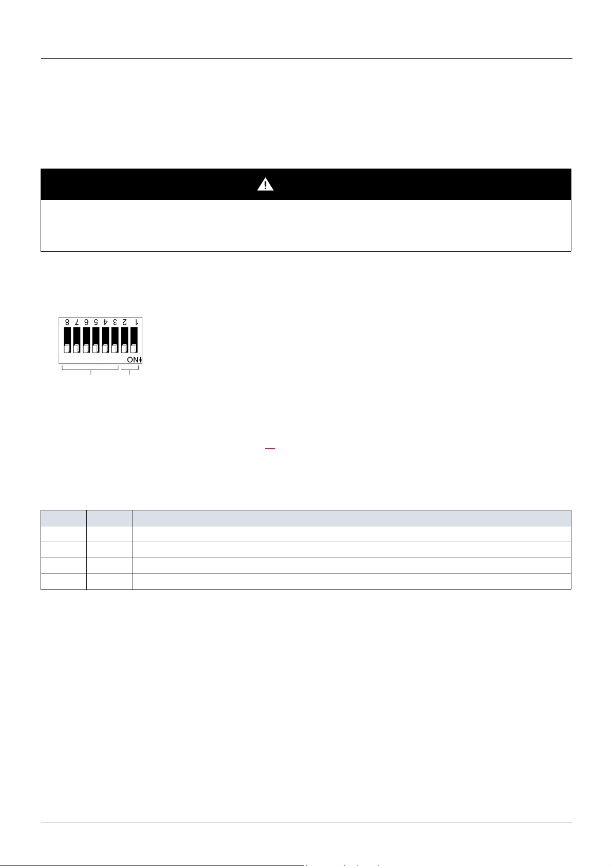
Coding the switches
Switches description
High = OFF = 0
Low = ON = 1
Node address Data rate
Overriding the switches
When switches 2 and 1 are set in position low (ON = 1), the data rate of the drive must be set by a network tool (refer to the chapter
"Integration of the ATV312 in a DeviceNet network", page 21
). Default values are 125 kbit/s and node address 63.
Coding the data rate
All devices connected to the DeviceNet network must communicate at the same data rate: 125, 250, or 500 kbit/s. The table below shows
the switch settings that configure the DeviceNet data rate on the drive.
Switch 2 Switch 1 Data rate
0 0 125 kbit/s
0 1 250 kbit/s
1 0 500 kbit/s
1 1 The DeviceNet data rate of the drive must be set by a network tool.
Any change to the switch setting takes effect at the next power-up.
14 S1A10387 09/2012

Configuration
Data rate = 250 kbit/s (switches 1 and 2 = 2#01)
Node address = 25 (switches 3 to 8 = 2#01 1001)
Data rate = 500 kbit/s (switches 1 and 2 = 2#10)
Node address = 52 (switches 3 to 8 = 2#11 0100)
Coding the node address
All devices connected to the DeviceNet network must have a unique address, ranging from 0 to 63 (decimal).
The table below lists the switch setting for each valid node address.
Any change to the switch setting takes effect at the next power-up.
Node
address
00 00 0000 16 01 0000 32 10 0000 48 11 0000
01 00 0001 17 01 0001 33 10 0001 49 11 0001
02 00 0010 18 01 0010 34 10 0010 50 11 0010
03 00 0011 19 01 0011 35 10 0011 51 11 0011
04 00 0100 20 01 0100 36 10 0100 52 11 0100
05 00 0101 21 01 0101 37 10 0101 53 11 0101
06 00 0110 22 01 0110 38 10 0110 54 11 0110
07 00 0111 23 01 0111 39 10 0111 55 11 0111
08 00 1000 24 01 1000 40 10 1000 56 11 1000
09 00 1001 25 01 1001 41 10 1001 57 11 1001
10 00 1010 26 01 1010 42 10 1010 58 11 1010
11 00 1011 27 01 1011 43 10 1011 59 11 1011
12 00 1100 28 01 1100 44 10 1100 60 11 1100
13 00 1101 29 01 1101 45 10 1101 61 11 1101
14 00 1110 30 01 1110 46 10 1110 62 11 1110
15 00 1111 31 01 1111 47 10 1111 63 11 1111
Switches
876543
Node
address
Switches
876543
Node
address
Switches
876543
Node
address
Switches
876543
Examples
S1A10387 09/2012 15

Configuring by the drive HMI
Configuring the control
Principle
By the configuration of the control, it is possible to decide from what channel the drive receives its commands and setpoint, either
permanently or depending on a switching command.
Numerous configurations are possible. For more information, refer to the Programming manual and Communication parameters manual.
The following configurations are some of the possibilities available.
The choice of the assembly set is defined by the application at the DeviceNet scanner level. It cannot be set at the device level. See the
paragraph "Assembly Selection" in the chapter "Integration of the ATV312 in a DeviceNet network", page 26
M Control with native profile
• 100: Native profile control input made of CMD and LFR
• 101: Native profile control output made of ETA and RFR
.
Please refer to the chapter "Supervision and control in LINE mode", page 28
M Control according to ODVA AC drive profile
The ODVA AC drive profile is activated when one of the following assemblies is selected:
• 20: Basic speed control output
• 21: Extended speed control output
• 70: Basic speed control input
• 71: Extended speed control input
The advantage of using the ODVA drive profile standard is the interchangeability with other brands.
The DeviceNet card translates the commands, behaviour and monitoring information from of ODVA profile (on the network) to the Drivecom
profile (in the drive).
.
Available configurations
M If you use the native profile:
• 100: Native command Word and speed reference (CMD and LFRD)
• 101: Native status and current speed (ETA and RFRD)
The examples below are only possible if you use the communication scanner.
M If you use the ODVA AC drive profile, that is, the assemblies:
• 20: Basic speed control output
Byte Bit 7 Bit 6 Bit 5 Bit 4 Bit 3 Bit 2 Bit 1 Bit 0
0
Fault reset Run fwd
1
2
3
• 21: Extended speed control output
Byte Bit 7 Bit 6 Bit 5 Bit 4 Bit 3 Bit 2 Bit 1 Bit 0
0
1
2
3
16 S1A10387 09/2012
NetRef NetCtrl Fault reset Run rev Run fwd
Speed reference (Low byte)
Speed reference (High byte)
Speed reference (Low byte)
Speed reference (High byte)

Configuring by the drive HMI
Terminals/Keypad
Remote display terminal
Forced local mode
NET:
DeviceNet
or any communication
option
• 70: Basic speed control input
Byte Bit 7 Bit 6 Bit 5 Bit 4 Bit 3 Bit 2 Bit 1 Bit 0
0
1
Running1 Faulted
2
3
• 71: Extended speed control input
Byte Bit 7 Bit 6 Bit 5 Bit 4 Bit 3 Bit 2 Bit 1 Bit 0
0
1
2
3
At
reference
Ref from
net
Ctrl from
net
Speed actual (Low byte)
Speed actual (High byte)
Ready Running2
(Rev)
Drive state
Speed actual (Low byte)
Speed actual (High byte)
Running1
(Fwd)
Warning Faulted
Control signal of an ATV312 from DeviceNet or from a communication card
There are several ways to control an ATV 312 from a communication card:
• The control word and the speed reference are controlled from the network in the same time.
• The control word and the speed reference come from separate sources.
However separate mode is only allowed when the [ACCESS LEVEL] (LAC) parameter in the [COMMAND] (CtL-) menu is set to L3.
The Control of the drive is also detailed in the programming manual of the ATV312 in the chapter "Control Menu".
Control of the drive when LAC = L1 or L2
There is now particular settings, the channels are managed in order of priority.
Control of the drive when LAC = L3
When configured with LAC = L3 several configurations are possible:
Control and reference come from the communication card
The command and the target come from DeviceNet.
Control is in native profile (CiA402).
S1A10387 09/2012 17
 Loading...