

Schneider ATV312H055M2, ATV312HU30N4, ATV312H037M2, ATV312HU15N4, ATV312H055N4 User Manual
...
Quick Start Guide - ATV312
ENGLISH
1
2
3
S1A1094203
DANGER
HAZARD OF ELECTRIC SHOCK, EXPLOSION, OR ARC FLASH
• Only appropriately trained persons who are familiar with and understand the contents of this manual and all other pertinent product
documentation and who have received safety training to recognize and avoid hazards involved are authorized to work on and with this drive
system. Installation, adjustment, repair and maintenance must be performed by qualified personnel.
• The system integrator is responsible for compliance with all local and national electrical code requirements as well as all other applicable
regulations with respect to grounding of all equipment.
• Many components of the product, including the printed circuit boards, operate with mains voltage. Do not touch. Use only electrically
insulated tools.
• Do not touch unshielded components or terminals with voltage present.
• Motors can generate voltage when the shaft is rotated. Prior to performing any type of work on the drive system, block the motor shaft to
prevent rotation.
• AC voltage can couple voltage to unused conductors in the motor cable. Insulate both ends of unused conductors of the motor cable.
• Do not short across the DC bus terminals or the DC bus capacitors or the braking resistor terminals.
• Before performing work on the drive system:
- Disconnect all power, including external control power that may be present.
- Place a "Do Not Turn On" label on all power switches.
- Lock all power switches in the open position.
- Wait 15 minutes to allow the DC bus capacitors to discharge. The DC bus LED is not an indicator of the absence of DC bus voltage that
can exceed 800 Vdc.
- Measure the voltage on the DC bus between the DC bus terminals using a properly rated voltmeter to verify that the voltage is < 42 Vdc.
- If the DC bus capacitors do not discharge properly, contact your local Schneider Electric representative.
• Install and close all covers before applying voltage.
Failure to follow these instructions will result in death or serious injury.
Electrical equipment should be installed, operated, serviced, and maintained only by qualified personnel. No responsibility is assumed by Schneider
Electric for any consequences arising out of the use of this product.
Information below is designed to use single drive connected to single motor with a motor cable length less than 50 meters (164 ft).
In any other case, consult the ATV312 installation manual (BBV46391) and programming manual (BBV46385) on www.schneider-electric.com.
Check the delivery of the drive
• Remove ATV312 from the packaging and check that it has not been damaged.
WARNING
DAMAGED DRIVE EQUIPMENT
Do not operate or install any drive or drive accessory that appears damaged.
Failure to follow these instructions can result in death, serious injury, or equipment damage.
• Check that the drive reference printed on the label matches the delivery note and corresponding purchase order.
Write the drive Model Reference: _____________ ___________and Serial Number: ____________________________
Check the line voltage compatibility
• Check that the line voltage is compatible with the supply range of the drive.
Line voltage _______ Volts / Drive voltage range _______ Volts
Drive range: ATV312ppppM2 = 200/240 V single phase / ATV312ppppM3=200/240 V three-phase
ATV312ppppN4 = 380/500 V three-phase / ATV312ppppS6 = 525/600 V three-phase
Mount the drive vertically
For a surrounding air temperature up to 50 °C (122 °F)
8B0917121134
(a)
(a)
(a)
See installation manual (BBV46391) on www.schneider-electric.com for other thermal conditions.
www.schneider-electric.com 1/4 S1A10942 - 04/2014
(a)
(a) 50 mm (2 in.)
(b)
(b) 10 mm (0.4 in.)
4
ATV312 M2
ATV312 M3
ATV312 N4
ATV312 S6
200/240 V
380/500 V
525/600 V
REF
RUN
CAN
ERR
MON
CONF
200/240 V
or
See
SCCR annex
5
5.1
+10 v
AI 1
COM
2.2 KΩ
24 V
LI2
LI1
LIx
ATV 312
LI1: forward
LI2: reverse
LI1: stop
Control command 2-wire:
Control command 3-wire:
LI2: forward
LIx: reverse
OR
5.2
6
7
8
7
5.1
5.2
6
9.2
ENT
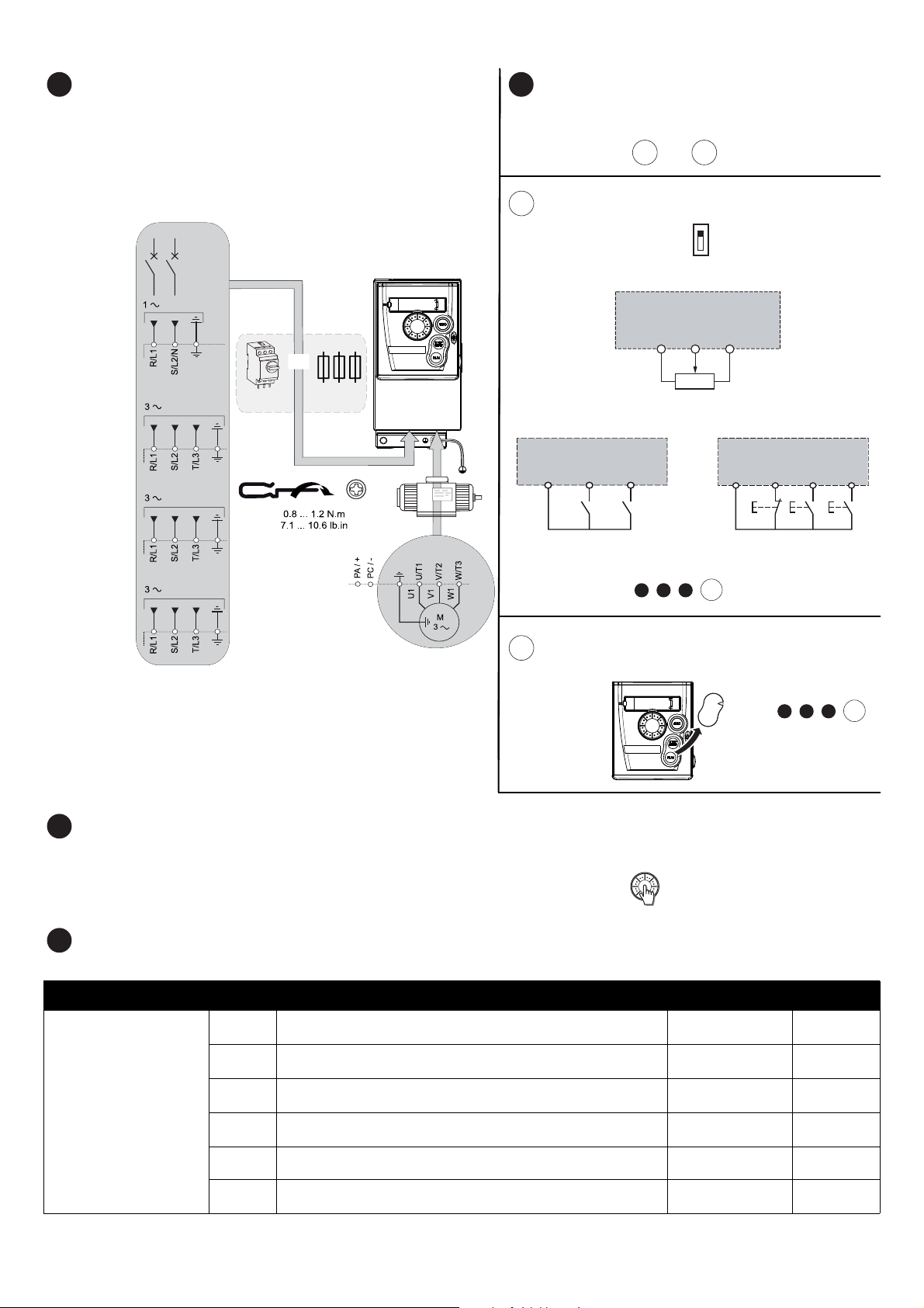
Connect power wiring
• Wire the drive to the ground.
• Check circuit breaker rating or fuse rating (see SCCR annex)
• Check that the motor voltage is compatible with the drive voltage.
Motor voltage ______Volts.
• Wire the drive to the motor.
• Wire the drive to the line supply.
Connect control wiring and select control configuration: or
[REMOTE configuration]
(Control by external reference)
Source
• Ensure SW1 = ‘’SOURCE’’
• Wire the speed reference:
• Wire the command:
ATV 312
LI1
24 V
LI2
CLI
SINK
•Next steps, do:
+ + +
6
9.1
[LOCAL configuration]
(control by internal reference)
CONF
RUN
REF
CAN
MON
ERR
.
Do: + + +
Apply power to the drive
• Ensure that Logic Inputs are not active (see Li1, Li2, Lix ).
• Apply power to the drive.
• At first power up, the drive displays nSt (3-wire control) or rdY(2 -wire control), after pushed drive displays bFr.
• On next start-ups, the drive displays nStor rdY .
Set motor parameters
• Refer to the motor nameplate for the following parameter settings.
[MOTOR CONTROL]
www.schneider-electric.com 2/4 S1A10942 - 04/2014
Menu Code Description Factory setting
drC-
[Standard mot. freq]:
bFr
UnS
FrS
nCr
nSP
COS
Standard motor frequency (Hz)
[Rated motor volt.]:
Nominal motor voltage on motor nameplate (V)
[Rated motor freq.]:
Nominal motor frequency on motor nameplate (Hz)
[Rated mot. current.]:
Nominal motor current on motor nameplate (A)
[Rated motor speed]:
Nominal motor speed on motor nameplate (rpm)
[Motor 1 Cosinus Phi.]:
Nominal motor cos
50.0
drive rating
50.0
drive rating
drive rating
ϕ on motor nameplate
drive rating
87
Customer
setting

Set motor parameters
7
8
9
9.1
9.2
10
LOC
35.1
rdY
3s
MODE
[Output frequency] (Hz)
• Set tUn parameter to YES.
Menu Code Description Factory setting
drC-
[MOTOR CONTROL]
tUn
DANGER DANGER
HAZARD OF ELECTRIC SHOCK OR ARC FLASH
• During auto-tuning, the motor operates at rated
current.
• Do not service the motor during auto-tuning.
Failure to follow these instructions will result in death
or serious injury.
Set basic parameters
Menu Code Description Factory setting
ACC
dEC
SEt-
[SETTINGS]
I-O-
[INPUTS / OUTPUTS CFG]
Fun-> PSS-
[PRESET SPEEDS]
Fun-> SAI-
[SUMMING INPUTS]
LSP
HSP
ItH
rrS
PS2
PS4
SA2
[Auto Tunning]:
Auto-Tunning for UnS, FrS, nCr, nSP and COS
[Acceleration]:
Acceleration time (s)
[Deceleration]:
Deceleration time (s)
[Low speed]:
Motor frequency at minimum reference (Hz)
[High speed]:
Motor frequency at maximum reference (Hz)
[Mot. therm. current]:
Nominal current on motor nameplate (A)
[Reverse assign.]:
Reverse assignment
[2 preset speeds]:
Preset speeds
[4 preset speeds]:
Preset speeds
[Summing ref. 2]
Analog input
(continued)
UNINTENDED EQUIPMENT OPERATION
•The Nominal Motor Parameters UnS, FrS, nCr, nSP and COS
• If one or more of these parameters is modified after auto-tuning has
Failure to follow these instructions will result in death or serious inju ry.
Customer
setting
nO
must be correctly configured before starting auto-tuning.
been performed, tUn will return to nOand the procedure must be
repeated.
Customer
setting
3.0
3.0
0.0
50.0
drive rating
LI2
LI3
LI4
AI2
Set control choice
Menu Code Description 5.1 [REMOTE configuration] 5.2 [LOCAL configuration] Customer Setting
CtL-
[COMMAND]
I-O-
[INPUTS / OUTPUTS CFG]
[REMOTE configuration]
(Factory setting)
Factory settings of parameters:
Fr1= AI1
tCC= 2C
Fr1
tCC
[Ref.1 channel]:
Reference control
[2/3 wire control]:
Command control
Al1 (factory setting),
Al2, Al3
2C: 2-wire (factory setting)
3C: 3-wire
[LOCAL configuration]
Factory settings of parameters:
Fr1= AIU1
tCC= LOC
= LI2
rrS
= LI3
PS2
= LI4
PS4
AlU1
LOC
Start the motor
www.schneider-electric.com 3/4 S1A10942 - 04/2014

Menus structure
SEt- ACC
dEC
26.
26.
15.
= ENT
SFr
ESC
ESC
ENT ENT
ENT
ESC
These 3 parameters are
only visible at first power up
of the drive.
Settings can be changed
subsequently in menu:
drC- for bFr
CtL- for Fr1
I-O- for tCC.
[SPEED REFERENCE]
[SETTINGS]
[MOTOR CONTROL]
[INPUTS / OUTPUTS CFG]
[COMMAND]
[APPLICATION FUNCT.]
[FAULT MANAGEMENT]
= ENT
bFr
Fr1
tCC
rEF-
SEt-
drC-
I-O-
CtL-
FUn-
FLt-
MODE
MODE
3s
LOC
rEN
MODE
3s
rdY
35.
ESC
2s
[Output frequency] (Hz)
rdY
ESC ENT
[COMMUNICATION]
[MONITORING]
COM-
SUP-
1 flash
(save)
Parameter selection
Refer to the programming manual (BBV46385) for comprehensive menu descriptions.
A dash appears after menu codes to differentiate them from parameter codes.
Example:
[SETTINGS] (SEt-), ACC parameter.
www.schneider-electric.com 4/4 S1A10942 - 04/2014
 Loading...