

Page 1
Altivar 31pppT
Variable speed drives
Programming manual
Traverse control
for asynchronous motors
Traverse control
Page 2

Page 3

Table of contents
Warnings____________________________________________________________________________________________________ 2
Using the traverse control programming manual _____________________________________________________________________ 3
Factory configuration __________________________________________________________________________________________ 4
Function compatibility __________________________________________________________________________________________ 5
List of functions which can be assigned to inputs/outputs ______________________________________________________________ 6
Settings menu SEt- and motor control menu drC- ____________________________________________________________________ 7
I/O menu I-O- ________________________________________________________________________________________________ 8
Control menu CtL- ____________________________________________________________________________________________ 9
Application functions menu FUn- ________________________________________________________________________________ 11
Display menu SUP- __________________________________________________________________________________________ 22
Configuration/Settings table ____________________________________________________________________________________ 23
Communication variables ______________________________________________________________________________________ 24
NOTE: Please also refer to the "Installation
Manual" and the "Altivar 31 Programming
Manual".
1
Page 4

Warnings
When the drive is powered up, the power components and some of the control
components are connected to the line supply. It is extremely dangerous to touch
them. The drive cover must be kept closed.
In general, the drive power supply must be disconnected before any operation on
either the electrical or mechanical parts of the installation or machine.
After the ALTIVAR has been switched off and the display has disappeared
completely, wait for 10 minutes before working on the equipment. This is the time
required for the capacitors to discharge.
The motor can be stopped during operation by inhibiting start commands or the
speed reference while the drive remains powered up. If personnel safety requires
prevention of sudden restarts, this electronic locking system is not sufficient: fit
a cut-off on the power circuit..
The drive is fitted with safety devices which, in the event of a fault, can shut down
the drive and consequently the motor. The motor itself may be stopped by a
mechanical blockage. Finally, voltage variations, especially line supply failures,
can also cause shutdowns.
If the cause of the shutdown disappears, there is a risk of restarting which may
endanger certain machines or installations, especially those which must
conform to safety regulations.
In this case the user must take precautions against the possibility of restarts, in
particular by using a low speed detector to cut off power to the drive if the motor
performs an unprogrammed shutdown.
The drive must be installed and set up in accordance with both IEC international
and national standards. Bringing the device into conformity is the responsibility
of the systems integrator who must observe the EMC directive among others
within the European Union.
The specifications contained in this document must be applied in order to
comply with the essential requirements of the EMC directive.
The Altivar 31 must be considered as a component: it is neither a machine nor a
device ready for use in accordance with European directives (machinery
directive and electromagnetic compatibility directive). It is the responsibility of
the end user to ensure that the machine meets these standards.
The drive must not be used as a safety device for machines posing a potential
risk of material damage or personal injury (lifting equipment, for example). In
such applications, overspeed checks and checks to ensure that the trajectory
remains under constant control must be made by separate devices which are
independent of the drive.
The products and equipment described in this document may be changed or
modified at any time, either from a technical point of view or in the way they are
operated. Their description can in no way be considered contractual.
2
Page 5

Using the traverse control programming manual
This document should be used in conjunction with the Altivar 31 programming manual.
It describes functions and parameters that are additional or different to the Altivar 31.
Differences from the Altivar 31
• The PowerSuite software workshop cannot be used with the Altivar31pppT
• Different factory configuration (see page 4
• Compatibility of the different functions (see page 5
• Assignments of the different analog/logic output and relays (see page 8
• Diagrams of the different reference channel (see pages 9
• Application functions menu FUn-:
- Addition of the Traverse control sub-menu: tCO- (see page 17
- Different PI Regulator sub-menu: PI- (see page 20
- Deletion of Brake control menu: bLC-
- Deletion of Management of limit switch menu: LSt-
• Display menu SUP
- Addition of parameters relating to the PI function and the traverse control function (see page 22
)
)
)
and 10)
)
)
)
3
Page 6

Factory configuration
Factory settings
Factory settings which are specific to the AltivarpppT are underlined.
The Altivar 31 is factory-set for the most common operating conditions:
• Display: Drive ready (rdY) with motor stopped, and motor frequency with motor running
• Motor frequency (bFr): 50 Hz
• Constant torque application (UFt = L)
• Suppression of the speed loop filter (SrF = YES)
• Normal stop mode on deceleration ramp (Stt = rMP).
• Stop mode in the event of a fault: Freewheel
• Linear ramps (ACC, dEC): 3 seconds
• Low speed (LSP): 0 Hz
• High speed (HSP): 50 Hz
• Motor thermal current (ItH) = Nominal motor current (value depending on drive rating)
• Standstill injection braking current (SdC1) = 0.7 x nominal drive current, for 0.5 seconds
• Automatic adaptation of the deceleration ramp in the event of overvoltage on braking
• No automatic restarting after a fault
• Switching frequency 4 kHz
• Logic inputs:
- LI1: Forward, 2-wire transition detection control, non-reversing, inactive on the ATV31
LI2: Inactive (not assigned)
-
- LI3: Traverse control command
- LI4: Inactive (not assigned)
- LI5 - LI6: Inactive (not assigned)
• Analog inputs:
- AI1: Speed reference 0-10 V, inactive on ATV 31
- AI2: Summed speed reference input 0±10 V
- AI3: 4-20 mA inactive (not assigned)
• Relay R1: The contact opens in the event of a fault (or drive off)
• Relay R2: Inactive (not assigned)
• Analog output AOC: 0-20 mA inactive (not assigned)
.
ppppppAT drives (not assigned)
ppppppAT.
ATV 31ppppppAT range
When they leave the factory, ATV 31ppppppAT drives are supplied with local control activated: the RUN, STOP buttons and the drive
potentiometer are active. Both logic input LI1 and analog input AI1 are inactive (not assigned).
If the above values are compatible with the application, the drive can be used without changing the settings.
4
Page 7

Function compatibility
Incompatible functions
The following functions will be inaccessible or deactivated in the cases described below:
Automatic restart
This is only possible for 2-wire level detection control (tCC = 2C and tCt = LEL or PFO).
Flying restart
This is only possible for 2-wire level detection control (tCC = 2C and tCt = LEL or PFO).
This function is locked if the automatic DC injection on stopping is configured as Continuous (AdC = Ct).
Reverse
On the ATV31pppAT range only, this function is locked if local control is active (tCC = LOC).
Function compatibility table
The choice of application functions may be limited by the number of I/O and by the fact that some functions are incompatible with one
another. Functions which are not listed in this table are fully compatible.
If there is an incompatibility between functions, the first function configured will prevent the remainder being configured.
To configure a function, first check that functions which are incompatible with it are unassigned, especially those which are
assigned in the factory setting.
Summed inputs (factory setting)
+/- speed (1)
Traverse control (factory setting)
Preset speeds
PI regulator
JOG operation
Summed inputs (factory setting)
+/- speed (1)
Traverse control (factory setting)
Preset speeds
PI regulator
JOG operation
Motor switching
DC injection stop
Quick stop
Freewheel stop
(1)Excluding special application with reference channel Fr2 (see diagrams on pages 9
Incompatible functions Compatible functions N/A
p
Priority functions (functions which cannot be active at the same time):
XA
Stop functions have priority over run commands.
Speed references via logic command have priority over analog references.
The function indicated by the arrow has priority over the
other.
pAA
p ppp
Xp pA
ppp
Xp Xp
X
Motor switching
A
p A
DC injection stop
Quick stop
p
XX
and 10)
Freewheel stop
A
5
Page 8

List of functions which can be assigned to inputs/outputs
Logic inputs
The assignments Limit switch forward LAF and Limit switch reverse LAr are not available on the ATV31pppT.
Addition of assignments to the "Traverse control" function.
Analog inputs
Unchanged.
Analog/logic output
Addition of assignments to the "Traverse control" function.
No "brake sequence" assignment.
Relay
Addition of assignments to the "Traverse control" function.
No "brake sequence" assignment.
6
Page 9
Settings menu SEt- and motor control menu drC-
Settings menu SET-
Unchanged.
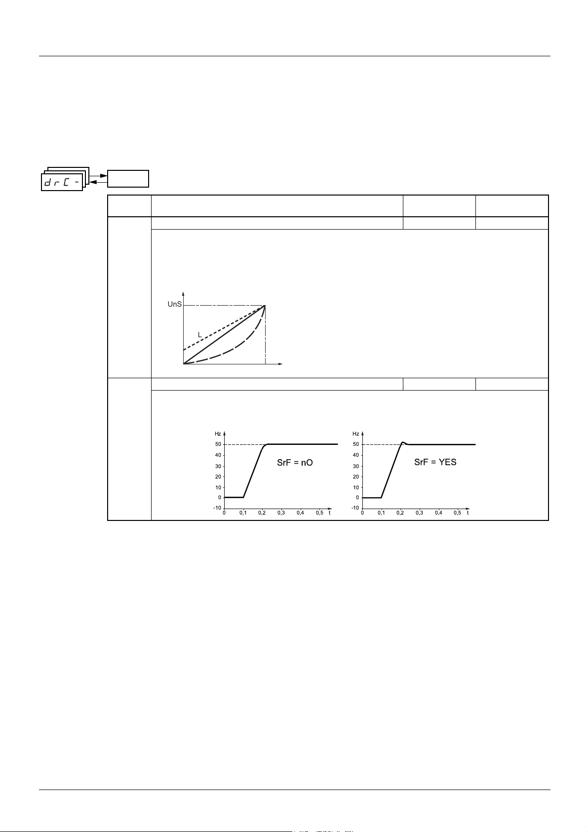
Motor control menu drC-
Unchanged except for the factory setting of parameter UFt which is now "L" and the factory setting of parameter SrF which is now "YES".
drC-
Code Description Adjustment
Factory setting
range
UFt Selection of the type of voltage/frequency ratio L
L: Constant torque for motors connected in parallel or special motors
P: Variable torque: Pump and fan applications
n: Sensorless flux vector control for
constant torque applications
nLd: Energy saving, for variable torque applications not requiring high dynamics (behaves in a similar way
to the P ratio at no load and the n ratio on load).
Voltage
UnS
L
n
P
FrS
Frequency
SrF Suppression of the speed loop filter YES
nO: The speed loop filter is active (prevents the reference being exceeded).
YES: The speed loop filter is suppressed (in position control applications, this reduces the response time
and the reference may be exceeded).
7
Page 10

I/O menu I-O-
Unchanged except for the analog/logic output and relay assignments:
• No "brake sequence" assignment
• Addition of the "end of reel" assignment
• Addition of the "counter wobble synchronization" assignment
Code Description Factory setting
dO Analog/logic output AOC/AOV nO
nO: Not assigned
OCr: Motor current. 20 mA or 10 V corresponds to twice the nominal drive current
OFr: Motor frequency. 20 mA or 10 V corresponds to the maximum frequency tFr
Otr: Motor torque. 20 mA or 10 V corresponds to twice the nominal motor torque
OPr: Power supplied by the drive. 20 mA or 10 V corresponds to twice the nominal drive power.
Making the following assignments (1) will transform the analog output to a logic output (see the diagram in
the Installation Manual):
FLt: Drive fault
rUn: Drive running
FtA: Frequency threshold reached (Ftd parameter in the SEt- menu)
FLA: High speed (HSP) reached
CtA: Current threshold reached (Ctd parameter in the SEt- menu)
SrA: Frequency reference reached
tSA: Motor thermal threshold reached (ttd parameter in the SEt- menu)
APL: Loss of 4-20 mA signal, even if LFL = nO
: End of reel (parameter tbO, page 17)
EbO
: "Counter wobble" synchronization. To be configured on the thread guide drive (master) only. See
CLO
page 15
The logic output is at state 1 (24 V) when the selected assignment is active, with the exception of FLt (state
1 if the drive is not faulty).
(1) With these assignments, configure AO1t = 0A.
r1 Relay r1 FLt
nO: Not assigned
FLt: Drive fault
rUn: Drive running
FtA: Frequency threshold reached (Ftd parameter in the SEt- menu)
FLA: High speed (HSP) reached
CtA: Current threshold reached (Ctd parameter in the SEt- menu)
SrA: Frequency reference reached
tSA: Motor thermal threshold reached (ttd parameter in the SEt- menu)
APL: Loss of 4-20 mA signal, even if LFL = nO
: End of reel (parameter tbO, page 17)
EbO
: "Counter wobble" synchronization. To be configured on the thread guide drive (master) only. See
CLO
page 15
The relay is powered up when the selected assignment is active, with the exception of FLt (powered up if
the drive is not faulty).
r2 Relay r2 nO
nO: Not assigned
FLt: Drive fault
rUn: Drive running
FtA: Frequency threshold reached (Ftd parameter in the SEt- menu)
FLA: High speed (HSP) reached
CtA: Current threshold reached (Ctd parameter in the SEt- menu)
SrA: Frequency reference reached
tSA: Motor thermal threshold reached (ttd parameter in the SEt- menu)
APL: Loss of 4-20 mA signal, even if LFL = nO
: End of reel (parameter tbO, page 17)
EbO
: "Counter wobble" synchronization. To be configured on the thread guide drive (master) only. See
CLO
page 15
The relay is powered up when the selected assignment is active, with the exception of FLt (powered up if
the drive is not faulty).
8
Page 11

Control menu CtL-
Menu unchanged, but different diagrams: summed input placed after the PI
Reference channel for LAC = L1 or
Fr1
+
UPdt
UPdH
AI1
AI2
AI3
AIP
SA2
nO
AI1
AI2
AI3
AIP
SA3
speed
A
Function
page 18
speed
PI
see
Preset speeds
nO
(SP1)
SP2
SP16
LI
L2
Remote
display
terminal
LFr
LI
Jog
operation
Note: If the +/- speed command is
configured (Fr1 = UPdt or UPdH),
summed inputs SA2/SA3 are not active.
Ref: Traverse control function
base reference.
AI1
AI2
AI3
AIP
UPdt
UPdH
AI1
AI2
AI3
AIP
Key:
nO
nO
Fr2
+
speed
B
speed
Parameter:
The black square represents
the factory setting assignment
Channel 1Channel 2
rFC
YES
nO
nO nO
LCC
Modbus
Forced local mode
CANopen
Ref
FLO
"Modbus" or "CANopen" is selected online by
writing the appropriate control word (see the busspecific documentation).
Function accessible for LAC = L2
Traverse
control
see
page 12
HSP
LSP
FrH
Ramps
ACC DEC
rFr
AC2 DE2
tdntUP
9
Page 12

Control menu CtL-
Reference channel for LAC = L3
LFr
Remote
display
terminal
LFr
Remote
display
terminal
LFr
Remote
display
terminal
UPdt
UPdH
AI1
AI2
AI3
AIP
LCC
Mdb
CAn
nO
AI1
AI2
AI3
AIP
LCC
Mdb
CAn
nO
AI1
AI2
AI3
AIP
LCC
Mdb
CAn
UPdt
UPdH
Fr1
SA2
SA3
Fr2
Function
A
+
speed
speed
PI
see
page 18
+
speed
speed
Note: If the +/- speed command is configured (Fr1 = UPdt or UPdH), summed inputs
SA2/SA3 are not active.
FLOC
Preset
speeds
(SP1)
SP2
SP16
Remote
display
terminal
LFr
nO
LI
AI1
AI2
AI3
AIP
LCC
Jog
LI
Mdb
CAn
operation
Ref: Traverse control function
base reference.
Channel 1
nO
rFC
LI
Traverse
Ref
nO
FLO
Forced local mode
control
see
page
12
HSP
LSP
FrH
ACC DEC
AC2 DE2
tUP
tdn
Ramps
rFr
Channel 2
B
LFr
Remote
display
terminal
10
nO
AI1
AI2
AI3
AIP
LCC
Mdb
CAn
Key:
Parameter:
The black square represents
the factory setting assignment
Page 13

Application functions menu FUn-
FUn-
ENT
ESC
ESC
ESC
tCO-
rPC-
FCS
ENT
ESC
ENT
ESC
ENT
ESC
ENT
ESC
ENT
ESC
Traverse control additional
sub-menu
Sub-menu
The parameters can only be modified when the drive is stopped and no run command is present.
On the optional remote display terminal, this menu can be accessed with the switch in the position.
Some functions have numerous parameters. In order to clarify programming and avoid having to scroll through endless parameters, these
functions have been grouped in sub-menus.
Like menus, sub-menus are identified by a dash after their code: for example.
There may be an incompatibility between functions (see the incompatibility table page 5
PSS-
). In this case, the first function configured
will prevent the remainder being configured.
Additional sub-menu: Traverse control: tCO-
Modified sub-menu: PI regulator: PI-
Deleted sub-menus: Brake control: bLC-
Management of limit switches: LSt-
11
Page 14

Application functions menu FUn-
Traverse control
Function for winding reels of thread (in textile applications)
Traverse control
drive
Traverse control motor
Winding
drive
Winding motor
Gearbox
Gearbox
Reel of thread
Main shaft
Thread guide
Thread
Cam
The cam speed of rotation must follow a precise profile to ensure that the reel is steady, compact and linear:
Run command
Traverse control
Command bit or LI
Motor speed
ACC ramp
Base reference
ACC
ramp
start of function
Bit 15 of word LRS1
(traverse control active)
t
t
dEC ramp
t
end of function
t
The function starts when the drive has reached its base reference and the traverse control command has been enabled.
When the traverse control command is disabled, the drive returns to its base reference, following the drive ACC or dEC ramp. The function
then stops, as soon as it has returned to this reference.
Bit 15 of word LRS1 is at 1 while the function is active.
12
Page 15

Application functions menu FUn-
Function parameters:
They define the cycle of frequency variations around the base reference, as shown in the figure below:
Motor speed
Base
reference
0
• trC: Traverse control command: Assignment of the traverse control command to a logic input or to a communication bus control word bit
• tdn: Traverse control deceleration time, in seconds
• tUP: Traverse control acceleration time, in seconds
• trH: "traverse frequency high" in Hertz
• trL: "traverse frequency low" in Hertz
• qSH "quick step high" in Hertz
• qSL "quick step low" in Hertz
tdn
tUP
Frequency skip
Frequency skip
qSH
trH
trL
qSL
t
Reel parameters:
• tbO: Time taken to make a reel, in minutes.
This parameter is intended to signal the end of winding. When the traverse control operating time since command trC reaches
the value of tbO, the logic output or one of the relays changes to state 1, if the corresponding function EbO has been assigned
in menu I-O-.
The traverse control operating time EbOt can be monitored online by a communication bus and in the Display menu SUP-.
• dtF: Decrease in the base reference.
In certain cases, it is necessary to reduce the base reference as and when the reel increases in size. The value dtF corresponds
to the time tbO. Once this time has elapsed, the reference continues to fall, following the same ramp.
If low speed LSP is at 0, the speed reaches 0 Hz, the drive stops and must be reset by a new run command.
If low speed LSP is anything but 0, the traverse control function continues to operate above LSP.
Motor speed
Base reference
0
Motor speed
Base reference
tbO
dtF
dtF
With LSP = 0
t
With LSP > 0
LSP
0
tbO
t
13
Page 16

Application functions menu FUn-
• rtr: Traverse control reset
This command can be assigned to a logic input or to a communication bus control word bit. It resets the EbO alarm and the EbOt
operating time to zero and reinitializes the reference to the base reference. As long as rtr remains at 1 the traverse control function
is inhibited and the speed remains the same as the base reference.
This command is mainly used when changing reels.
Motor speed
Base reference
dtF
Run
trC
0
tbO
0
0
t
t
t
EbOt
tbO
bit 15 of LRS1
EbO
rtr
0
0
0
0
t
t
t
t
14
Page 17

Application functions menu FUn-
Counter wobble
Master drive Slave drive
CLO SnC
Synchronization
Gearbox
Reel of thread
Main shaft
Winding motor
Thread
guide
Thread
Gearbox
Thread guide motor
Cam
The "Counter wobble" function is used, in certain applications, to obtain a constant thread tension when the Traverse control function causes
significant variations in speed on the thread guide motor (trH and trL see page 13
).
Two special "Traverse control" drives must be used (a master and a slave).
The master controls the speed of the thread guide, the slave controls the winding speed. The function gives the slave a speed ratio in
anti-phase with that of the master. A synchronization operation is therefore necessary, using a master logic output and a slave logic input.
Run command
affecting master and
slave
t
Traverse control
command affecting
master and slave
Thread guide motor
speed
(master drive)
CLO/SnC synchronization
Winding motor speed
(slave drive)
t
trH
trL
t
t
trH
trL
t
15
Page 18

Application functions menu FUn-
Connecting the synchronization I/O
Master drive Slave drive
ATV31 ATV31
(CLO) AOV
COM
Preferably, logic output AOV should be used.
The starting conditions for the function are:
- Base speeds of both drives reached
- "Traverse control command" input trC activated
- Synchronization signal present
Note: On the slave drive, parameters qSH and qSL should usually be left at zero.
LIp (SnC)
COM
16
Page 19

Application functions menu FUn-
FUn-
Code Description Adjustment
tCO- Traverse control
trC Traverse control command LI3
trH Traverse frequency high (1) 0 to 10 Hz 4 Hz
trL Traverse frequency low (1) 0 to 10 Hz 4 Hz
qSH Quick step high (1) 0 to trH 0 Hz
qSL Quick step low (1) 0 to trL 0 Hz
tUP Traverse control acceleration time (1) 0.1 to 999.9 s 4 s
tdn Traverse control deceleration time (1) 0.1 to 999.9 s 4 s
tbO Time taken to make a reel (1) 0 to 9999 minutes 0
dtF Decrease in the base reference (1) 0 to 500 Hz 0
rtr Traverse control reset nO
Caution the "Traverse control" function may be incompatible with other functions (see
)
page 5
nO: Not assigned
LI1: Logic input LI1
LI2: Logic input LI2
LI3: Logic input LI3
LI4: Logic input LI4
LI5: Logic input LI5
LI6: Logic input LI6
If LAC = L3, the following assignments are possible:
Cd11: Bit 11 of the Modbus or CANopen control word
Cd12: Bit 12 of the Modbus or CANopen control word
Cd13: Bit 13 of the Modbus or CANopen control word
Cd14: Bit 14 of the Modbus or CANopen control word
Cd15: Bit 15 of the Modbus or CANopen control word
nO: Not assigned
LI1: Logic input LI1
LI2: Logic input LI2
LI3: Logic input LI3
LI4: Logic input LI4
LI5: Logic input LI5
LI6: Logic input LI6
range
Factory setting
SnC "Counter wobble" synchronization nO
(1)Parameter can be adjusted during operation.
These parameters only appear if the function has been enabled by assignment of trC.
If LAC = L3, the following assignments are possible:
Cd11: Bit 11 of the Modbus or CANopen control word
Cd12: Bit 12 of the Modbus or CANopen control word
Cd13: Bit 13 of the Modbus or CANopen control word
Cd14: Bit 14 of the Modbus or CANopen control word
Cd15: Bit 15 of the Modbus or CANopen control word
nO: Not assigned (function inactive)
LI1: Logic input LI1
LI2: Logic input LI2
LI3: Logic input LI3
LI4: Logic input LI4
LI5: Logic input LI5
LI6: Logic input LI6
To be configured on the winding drive (slave) only.
17
Page 20

Application functions menu FUn-
PI regulator
Diagram
The function is activated by assigning an analog input to the PI feedback (measurement).
Internal
reference
rPI
YES
nO
Reference A
Pages 9
and 10
PII
(rP1)
rP2
rP3
rP4
LI
Pr2
Pr4
nO
inversion
nO
YES
Error
x1
x(-1)
PIC
+
-
Reference A
pages 9
Restart error
threshold
(wake-up)
tLS
rSL
0
Gains
and 10
Preset PI
PIF
nO
PI
feedback
AI1
AI2
AI3
Reference B Pages 9
references
FbS
x FbS
and 10
PI feedback:
The PI feedback must be assigned to one of the analog inputs (AI1, AI2 or AI3).
PI reference:
The PI reference can be assigned to the following parameters in order of priority:
- Preset references via logic inputs (rP2, rP3, rP4)
- Internal reference (rPI)
- Reference Fr1
rPG
PIF
rIG
POH
POL
nO
AI1
AI2
AI3
(auto)
(manu)
rFC
Key:
Parameter:
The black square
represents the
factory setting
assignment
HSP
FrH
LSP
Ramps
ACC DEC
AC2 DE2
tdn
tUP
rFr
Combination table for preset PI references
LI (Pr4) LI (Pr2) Pr2 = nO Reference
rPI or Fr1
00 rPI or Fr1
01 rP2
10 rP3
11 rP4
Adjustment parameters:
• Internal reference (rPI)
• Preset references (rP2, rP3, rP4)
• Regulator proportional gain (rPG)
• Regulator integral gain (rIG)
• FbS parameter:
The FbS parameter can be used to scale the reference on the basis of the variation range of the PI feedback (sensor rating).
E.g.: Regulation of the thread tension
PI reference (process) 0-5 Newton (0-100%)
Rating of tension sensor 0-10 Newton
FbS = Max. sensor scale/Max. process
FbS = 10/5= 2
• rSL parameter:
Can be used to set the PI error threshold above which the PI regulator will be reactivated (wake-up) after a stop due to the max. time
threshold being exceeded at low speed (tLS).
• Reversal of the direction of correction (PIC): If PIC = nO, the speed of the motor will increase when the error is positive, for example:
pressure control with a compressor. If PIC = YES, the speed of the motor will decrease when the error is positive, for example:
temperature control via a cooling fan.
• PI regulator min. (OPL) and max. (OPH) outputs.
Parameter which can be accessed in the display menu SUP-:
• PI feedback (rPF).
18
Page 21

Application functions menu FUn-
"Manual - Automatic" operation with PI
This function combines the PI regulator and the switching of reference rFC. The speed reference is given by Fr2 or by the PI function,
depending on the state of the logic input.
Setting up the PI regulator
1 Configuration in PI mode
See the diagram on page 18
2 Perform a test in factory settings mode (in most cases, this will be sufficient).
To optimize the drive, adjust rPG or rIG gradually and independently and observe the effect on the PI feedback in relation to the reference.
3 If the factory settings are unstable or the reference is incorrect:
Perform a test with a speed reference in Manual mode (without PI regulator) and with the drive on load for the speed range of the system:
- In steady state, the speed must be stable and comply with the reference and the PI feedback signal must be stable.
- In transient state, the speed must follow the ramp and stabilize quickly and the PI feedback must follow the speed.
If this is not the case, see the settings for the drive and/or sensor signal and cabling.
Switch to PI mode.
Set brA to nO (no auto-adaptation of the ramp).
Set the speed ramps (ACC, dEC) to the minimum permitted by the mechanics without triggering an ObF fault.
Set the integral gain (rIG) to minimum.
Observe the PI feedback and the reference.
Switch the drive ON/OFF a number of times or vary the load or reference rapidly.
Set the proportional gain (rPG) in order to ascertain the ideal compromise between response time and stability in transient phases (slight
overshoot and 1 to 2 oscillations before stabilizing).
If the reference varies from the preset value in steady state, gradually increase the integral gain (rIG), reduce the proportional gain (rPG)
in the event of instability (pump applications), find a compromise between response time and static precision (see diagram).
Perform in-production tests throughout the reference range.
.
Regulated value
Proportional
gain
Integral
gain
Reference
Reference
Reference
Stabilization time
rPG high
Overshoot
Static error
rPG low
Rise time
time
rIG high
rIG low
time
rPG and rIG correct
The oscillation frequency depends on the system kinematics.
Parameter Rise time Overshoot
rPG
rIG
Stabilization
time
=
time
Static error
19
Page 22

Application functions menu FUn-
FUn-
Code Description Adjustment range Factory setting
PI- PI regulator
PIF PI regulator feedback nO
nO: Not assigned
AI1: Analog input AI1
AI2: Analog input AI2
AI3: Analog input AI3
rPG PI regulator proportional gain (1) 0.01 to 100 1
Contributes to dynamic performance during rapid changes in the PI feedback.
rIG PI regulator integral gain (1) 0.01 to 100 1
Contributes to static precision during slow changes in the PI feedback.
FbS PI feedback multiplication coefficient (1) 0.1 to 100 1
For process adaptation
PIC Reversal of the direction of correction of the PI
regulator (1)
nO: normal
YES: reverse
Pr2 2 preset PI references nO
Selecting the assigned logic input activates the function.
nO: Not assigned
LI1: Logic input LI1
LI2: Logic input LI2
LI3: Logic input LI3
LI4: Logic input LI4
LI5: Logic input LI5
LI6: Logic input LI6
nO
If LAC = L3, the following assignments are possible:
Cd11: Bit 11 of the Modbus or CANopen control word
Cd12: Bit 12 of the Modbus or CANopen control word
Cd13: Bit 13 of the Modbus or CANopen control word
Cd14: Bit 14 of the Modbus or CANopen control word
Cd15: Bit 15 of the Modbus or CANopen control word
Pr4 4 preset PI references nO
Selecting the assigned logic input activates the function.
Check that Pr2 has been assigned before assigning Pr4.
nO: Not assigned
LI1: Logic input LI1
LI2: Logic input LI2
LI3: Logic input LI3
LI4: Logic input LI4
LI5: Logic input LI5
LI6: Logic input LI6
If LAC = L3, the following assignments are possible:
Cd11: Bit 11 of the Modbus or CANopen control word
Cd12: Bit 12 of the Modbus or CANopen control word
Cd13: Bit 13 of the Modbus or CANopen control word
Cd14: Bit 14 of the Modbus or CANopen control word
Cd15: Bit 15 of the Modbus or CANopen control word
rP2 2
rP3 3
rP4 4
nd
preset PI reference (1) 0 to 100% 30%
Only appears if Pr2 has been enabled by selecting an input.
rd
preset PI reference (1) 0 to 100% 60%
Only appears if Pr4 has been enabled by selecting an input.
th
preset PI reference (1) 0 to 100% 90%
Only appears if Pr4 has been enabled by selecting an input.
(1)Parameter can also be accessed in the settings menu SEt-, and can be adjusted during operation.
These parameters only appear if the function has been enabled by assignment of PIF.
20
Page 23

Application functions menu FUn-
FUn-
Code Description Adjustment
PI-
(continued)
(1)Parameter can also be accessed in the settings menu SEt-, and can be adjusted during operation.
(2)Parameter can be adjusted during operation
These parameters only appear if the function has been enabled by assignment of PIF.
rSL Restart error threshold ("wake-up" threshold) 0 to 100% 0
If the "PI" and "Low speed operating time" tLS functions are configured at the same time,
the PI regulator may attempt to set a speed lower than LSP.
This results in unsatisfactory operation which consists of starting, operating at low speed
then stopping, and so on…
Parameter rSL (restart error threshold) can be used to set a minimum PI error threshold
for restarting after a stop at prolonged LSP.
The function is inactive if tLS = 0.
PII Internal PI regulator reference nO
nO: The PI regulator reference is Fr1, except for UPdH and UPdt (+/- speed cannot be
used as the PI regulator reference).
YES: The PI regulator reference is internal via parameter rPI.
rPI Internal PI regulator reference (1) 0 to 100% 0
POH PI regulator max. output (2) 0 to 500 Hz 50
Maximum value of the regulator output (deadband). The factory setting is 50 Hz, or 60 Hz
if bFr is set to 60 Hz.
POL PI regulator min. output (2) 0 to 500 Hz 0
Minimum value of the regulator output, even when there are no errors.
range
Factory setting
21
Page 24

Display menu SUP-
Additional parameters:
• PI feedback
• Traverse control operating time
SUP-
Code Description Variation range
LFr Unchanged
rPI
rPF PI feedback 0 to 100%
FrH
Unchanged
tHd
EbOt Traverse control operating time 0 to 9999 minutes
LFt
to Unchanged
AI3A
These parameters only appear if the function has been enabled.
22
Page 25

Configuration/Settings table
Application functions menu
Code Factory setting Customer
tCO- trC LI3 PSS-
trH 4 Hz Hz SP10 50 Hz Hz
trL 4 Hz Hz SP11 55 Hz Hz
qSH 0 Hz Hz SP12 60 Hz Hz
qSL 0 Hz Hz SP13 70 Hz Hz
tUP 4 s s SP14 80 Hz Hz
tdn 4 s s SP15 90 Hz Hz
tbO 0 min min SP16 100 Hz Hz
dtF 0 Hz Hz JOG- JOG If tCC = 2C: nO
rtr nO If tCC = 3C: LI4
SnC nO If tCC = LOC: nO
rPC- rPt LIn
tA1 10% % UPd- USP nO
tA2 10% % dSP nO
tA3 10% % Str nO
tA4 10% % PI- PIF nO
ACC 3 s s
dEC 3 s s
rPS nO
Frt 0Hz
AC2 5 s s Pr2 nO
dE2 5 s s Pr4 nO
brA YES
StC- Stt rMP
FSt nO
dCF 4 rSL 0
dCI nO
IdC 0.7 In A rPI 0% %
tdC 0.5 s s POH 50 Hz Hz
nSt nO
AdC- AdC YES LC2- LC2 nO
tdC1 0.5 s s CL2 1.5 In (1) A
SdC1 0.7 In (1) A CHP- CHP nO
tdC2 0 s s UnS2 According to drive rating V
SdC2 0.5 In (1) A FrS2 50 Hz Hz
SAI- SA2 AI2
SA3 nO
PSS- PS2 If tCC = 2C: LI3
If tCC = 3C: LI4
If tCC = LOC: LI3
PS4 If tCC = 2C: LI4
If tCC = 3C: nO
If tCC = LOC: LI4
PS8 nO
PS16 nO
SP2 10 Hz Hz (1) In corresponds to the nominal drive current indicated in the
SP3 15 Hz Hz
SP4 20 Hz Hz These parameters only appear if the corresponding
SP5 25 Hz Hz
SP6 30 Hz Hz
SP7 35 Hz Hz
SP8 40 Hz Hz
FUn-
Code Factory setting Customer
setting
SP9 45 Hz Hz
JGF 10 Hz Hz
rPG 1
rIG 1
FbS 1
PIC nO
rP2 30% %
rP3 60% %
rP4 90% %
PII nO
POL 0 Hz Hz
nCr2 According to drive rating A
nSP2 According to drive rating RPM
COS2 According to drive rating
UFt2 n
UFr2 20% %
FLG2 20% %
StA2 20% %
SLP2 100 Hz Hz
installation manual and on the drive rating plate
function has been enabled. They can be adjusted during
operation.
setting
23
Page 26

Communication variables
The communication variables user's manual should be used, filling in the following information for the different or additional parameters.
NOTE:
The communication variables are listed with:
• Their address •••• in decimal format for Modbus
• Their index and subindex address ••••/•• in hexadecimal format for CANopen
Read/write
Whether the parameters have read and/or write access is indicated in the "Read/Write" column with the following codes:
• R: read only, drive stopped or running
• R/WS: read access when drive stopped or running and write access only when drive stopped
• R/W: read and write access when drive stopped or running
The variables or values specific to the ATV31
pppT are underlined.
Monitoring variables
Modbus
address
3250 2002 / 33 LRS1 R Extended status word No. 1
11981 2059 / 52 rPF R PI feedback
12209 205C / A EbOt R Traverse control operating time
CANopen
address
Code
Read/
Write
Name/Description/Possible values
bit 0: Reserved
bit 1 = 0: No drive fault
bit 1 = 1: Drive fault
bit 2 = 0: Motor stopped
bit 2 = 1: Motor running
bit 3: Reserved
bit 4 = 0: Frequency threshold (Ftd) not reached
bit 4 = 1: Frequency threshold (Ftd) reached
bit 5 = 0: High speed not reached
bit 5 = 1: High speed reached
bit 6 = 0: Current threshold (Ctd) not reached
bit 6 = 1: Current threshold (Ctd) reached
bit 7 = 0: Speed reference not reached
bit 7 = 1: Speed reference reached
bit 8 = 0: No motor thermal overload alarm
bit 8 = 1: Motor thermal overload alarm
bit 9: Reserved
bits 10 and 11: Reserved
bit 12 = 0: No loss of 4-20 mA fault
bit 12 = 1: Loss of 4-20 mA fault
bit 13: Reserved
bit 14 = 0: No drive thermal overload alarm
bit 14 = 1: Drive thermal overload alarm
bit 15 = 0: No traverse control
bit 15 = 1: Traverse control active
Unit: 0.01%
Unit: 1 minute
This parameter is reset by command rtr.
24
Page 27

Communication variables
Configuration and adjustment variables
Modbus
address
9607 2042 / 8 UFt R/WS Selection of the type of voltage/frequency ratio
9101 203D / 2 SrF R/WS Suppression of the speed loop filter
5031 2014 / 20 dO R/WS Analog/logic output AOC/AOV
CANopen
address
Code
Read/
Write
Name/Description/Possible values
Factory setting: 0
0 = "L": Constant torque for motors connected in parallel or special motors
1 = "P": Variable torque: Pump and fan applications
2 = "n": Sensorless flux vector control for constant torque applications
3 = "nLd": Energy saving, for variable torque applications not requiring high dynamics (behaves
in a similar way to the P ratio at no load and the n ratio on load).
Factory setting: 1
0 = "nO": The speed loop filter is active (prevents the reference being exceeded).
1 = "YES": The speed loop filter is suppressed (in position control applications, this reduces the
response time and the reference may be exceeded).
Factory setting: 0
0 = "nO": Not assigned
For the following assignments the output is analog type:
129 = "OCr": Motor current. 20 mA or 10 V corresponds to twice the nominal drive current.
130 = "OFr": Motor frequency. 20 mA or 10 V corresponds to the maximum frequency tFr
132 = "Otr": Motor torque. 20 mA or 10 V corresponds to twice the nominal motor torque.
139 = "OPr": Power supplied by the drive. 20 mA or 10 V corresponds to twice the nominal drive
power
For the following assignments the output is logic type (see diagram in the Installation Manual):
1 = "FLt": Drive fault
2 = "rUn": Drive running
4 = "FtA": Frequency threshold reached (Ftd parameter)
5 = "FLA": High speed (HSP) reached
6 = "CtA": Current threshold reached (Ctd parameter)
7 = "SrA": Frequency reference reached
8 = "tSA": Motor thermal threshold reached (ttd parameter)
12 = "APL": Loss of 4-20 mA signal, even if LFL = nO
101 = "EbO": End of reel
102 = "CLO": "Counter wobble" synchronization
The logic output is at state 1 (24 V) when the selected assignment is active, with the exception
of FLt (state 1 if the drive is not faulty).
5001 2014 / 2 r1 R/WS Relay r1
Factory setting: 1
0 = "nO": Not assigned
1 = "FLt": Drive fault
2 = "rUn": Drive running
4= "FtA": Frequency threshold reached (Ftd parameter)
5 = "FLA": High speed (HSP) reached
6 = "CtA": Current threshold reached (Ctd parameter)
7 = "SrA": Frequency reference reached
8 = "tSA": Motor thermal threshold reached (ttd parameter)
12 = "APL": Loss of 4-20 mA signal, even if LFL = nO
101 = "EbO": End of reel
102 = "CLO": "Counter wobble" synchronization
The relay is powered up when the selected assignment is active, with the exception of FLt
(powered up if the drive is not faulty).
With these assignments, configure AO1t = 0A.
(parameter tbO page 17)
(parameter tbO page 17)
25
Page 28

Communication variables
Configuration and adjustment variables
Modbus
address
5002 2014 / 3 r2 R/WS Relay r2
11952 2059 / 35 POL R/W PI regulator min. output
11953 2059 / 36 POH R/W PI regulator max. output
12201 205C / 2 trC R/WS Traverse control command
CANopen
address
Code
Read/
Write
Factory setting: 0
0 = "nO": Not assigned
1 = "FLt": Drive fault
2 = "rUn": Drive running
4 = "FtA": Frequency threshold reached (Ftd parameter)
5 = "FLA": High speed (HSP) reached
6 = "CtA": Current threshold reached (Ctd parameter)
7 = "SrA": Frequency reference reached
8 = "tSA": Motor thermal threshold reached (ttd parameter)
12 = "APL": Loss of 4-20 mA signal, even if LFL = nO
101 = "EbO": End of reel
102 = "CLO": "Counter wobble" synchronization
The relay is powered up when the selected assignment is active, with the exception of FLt
(powered up if the drive is not faulty).
Unit: 0.1 Hz
Factory setting: 0
Adjustment range: 0 to 5000
Unit: 0.1 Hz
Factory setting: 500 if bFr = 50 Hz,
600 if bFr = 60 Hz
Adjustment range: 0 to 5000
Factory setting: 0
0 = "nO": Not assigned
129 = "LI1": Logic input LI1
130 = "LI2": Logic input LI2
131 = "LI3": Logic input LI3
132 = "LI4": Logic input LI4
133 = "LI5": Logic input LI5
134 = "LI6": Logic input LI6
(parameter tbO page 17)
Name/Description/Possible values
If LAC = L3, the following assignments are possible:
171 = "Cd11": bit 11 of the CMD control word written by Modbus or CANopen
172 = "Cd12": bit 12 of the CMD control word written by Modbus or CANopen
173 = "Cd13": bit 13 of the CMD control word written by Modbus or CANopen
174 = "Cd14": bit 14 of the CMD control word written by Modbus or CANopen
175 = "Cd15": bit 15 of the CMD control word written by Modbus or CANopen
The function is activated when the logic state of the input or control word bit is at 1.
12202 205C / 3 trH R/W Traverse frequency high
12203 205C / 4 trL R/W Traverse frequency low
12204 205C / 5 qSH R/W Quick step high
12205 205C / 6 qSL R/W Quick step low
12206 205C / 7 tUP R/W Traverse control acceleration time
Unit: 0.01 Hz
Factory setting: 400
Adjustment range: 0 to 1000
Unit: 0.01 Hz
Factory setting: 400
Adjustment range: 0 to 1000
Unit: 0.01 Hz
Factory setting: 0
Adjustment range: 0 to trH
Unit: 0.01 Hz
Factory setting: 0
Adjustment range: 0 to trL
Unit: 0.1 s
Factory setting: 40
Adjustment range: 1 to 9999
26
Page 29

Communication variables
Configuration and adjustment variables
Modbus
address
12207 205C / 8 tdn R/W Traverse control deceleration time
12208 205C / 9 tbO R/W Time taken to make a reel
12210 205C / B rtr R/WS Traverse control reset
12211 205C / C dtF R/W Decrease in the base reference
12212 205C / D SnC R/WS "Counter wobble" synchronization
CANopen
address
Code
Read/
Write
Name/Description/Possible values
Unit: 0.1 s
Factory setting: 40
Adjustment range: 1 to 9999
Unit: 1 minute
Factory setting: 0
Adjustment range: 0 to 9999
Factory setting: 0
0 = "nO": Not assigned
129 = "LI1": Logic input LI1
130 = "LI2": Logic input LI2
131 = "LI3": Logic input LI3
132 = "LI4": Logic input LI4
133 = "LI5": Logic input LI5
134 = "LI6": Logic input LI6
If LAC = L3, the following assignments are possible:
171 = "Cd11": bit 11 of the CMD control word written by Modbus or CANopen
172 = "Cd12": bit 12 of the CMD control word written by Modbus or CANopen
173 = "Cd13": bit 13 of the CMD control word written by Modbus or CANopen
174 = "Cd14": bit 14 of the CMD control word written by Modbus or CANopen
175 = "Cd15": bit 15 of the CMD control word written by Modbus or CANopen
The function is activated when the logic state of the input or control word bit is at 1.
Unit: 0.1 Hz
Factory setting: 0
Adjustment range: 0 to 5000
Factory setting: 0
0 = "nO": Not assigned
129 = "LI1": Logic input LI1
130 = "LI2": Logic input LI2
131 = "LI3": Logic input LI3
132 = "LI4": Logic input LI4
133 = "LI5": Logic input LI5
134 = "LI6": Logic input LI6
The function is activated when the logic state of the input is at 1.
27
Page 30

DIA2ED3040202 EN
atv31_traverse control_EN_V1
2004-05
 Loading...