

Page 1
CAN interface for FMS
More information on the FMS standard can be found at www.fms-standard.com.
343 377
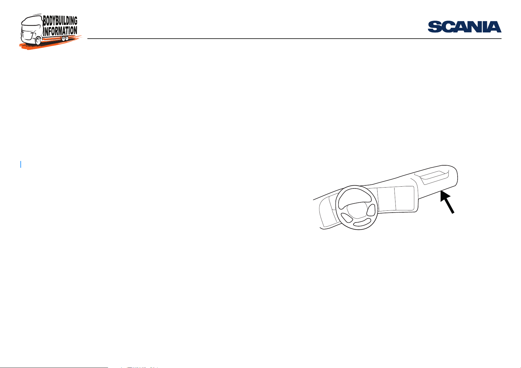
Connectors C137 and C471 are located under the central electric unit in the instru-
ment panel.
Introduction
This document contains information on the FMS standard, which is an open, common interface produced by many truck manufacturers. From October 2013 onwards,
FMS-Standard description Version 03 is supported.
Vehicle production period
Production site Chassis serial number
2013-10-11 -
Södertälje 2 091 978 -
Zwolle 5 337 011 -
Angers 9 180 458 -
Scania’s FMS interface is referred to in this document as RTG, and the bodybuilders’
links their own FMS network to the control unit via a connector.
From February 2009 onwards, the connection is made via connector C137:
Introduction
Vehicle production period
Production site Chassis serial number
2009-01-29 -
Södertälje 2 046 175 -
Zwolle 5 224 881 -
Angers 9 141 335 -
São Bernardo do Campo 3 644 065 -
11:90-02 Issue 7 en-GB 1 (92)
© Scania CV AB 2017, Sweden
Page 2
CAN interface for FMS
IMPORTANT!
From January 2009 onwards, the connection was made via connector C471:
Vehicle production period
Production site Chassis serial number
- 2009-01-28
Södertälje - 2 046 174
Zwolle - 5 224 880
Angers - 9 141 334
São Bernardo do Campo - 3 644 064
It is possible to install RTG with FMS Version 03 in older vehicles, but it is uncertain
if all messages will be sent. The reason for this is that the vehicle’s CAN bus does
not support all messages.
When installing RTG with FMS Version 03 in older vehicles, only the existing CAN
messages available in the CAN bus, which are described in this document, will be
sent.
Introduction
More information can be found in Connecting to RTG further on in this document.
Chassis serial number limits for the different FMS versions are indicated later in this
document.
It is not permitted to connect to any other connector or other CAN bus. An incorrect
connection could cause the normal functions of the truck to behave irrationally. The
truck may even stop and need to be towed.
11:90-02 Issue 7 en-GB 2 (92)
© Scania CV AB 2017, Sweden
Page 3
CAN interface for FMS
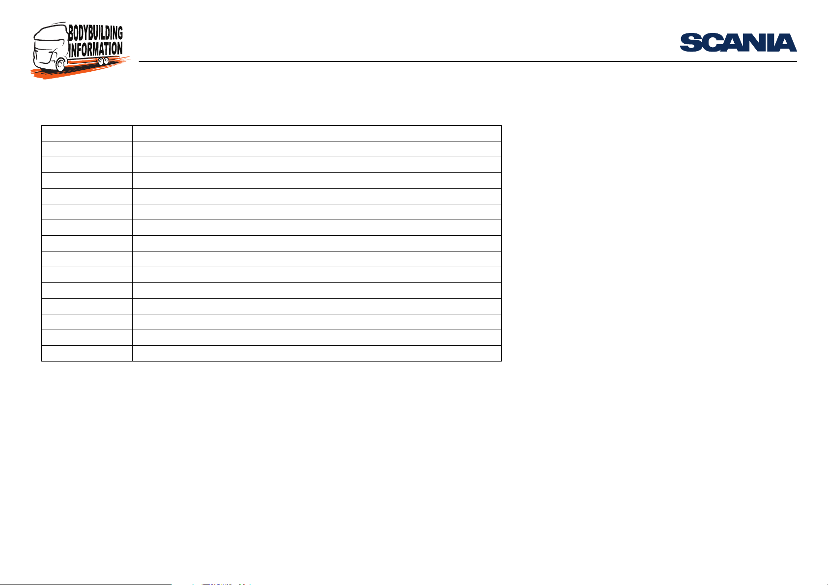
Abbreviations in this document
Abbreviation Explanation
CAN Controller Area Network
COO Koordinator
ECU Electronic Control Unit
FMS Fleet Management System
RTG Road Transport Informatics Gateway
ICL Instrument Cluster System
PGN Parameter Group Number
TCO Tachograph
EBS Electronic Brake System
DTCO Digital tachograph with remote driver card information downloading
OBD On-board diagnostics
EOBD European On-board Diagnostics
TP.CM Transport Protocol - Connection Management
TP.DT Transport Protocol - Data Transfer
Introduction
11:90-02 Issue 7 en-GB 3 (92)
© Scania CV AB 2017, Sweden
Page 4
CAN interface for FMS
Requirements for CAN communication with the vehicle
This section lists the requirements for CAN communication with the RTG control
unit on the external CAN bus. SAE J1939 forms the basis of the protocol, but large
parts are not implemented. These parts are SAE J1939-81 (Network Management),
main part of SAE J1939-73 (Diagnostics) and parts of SAE J1939-21 (Data Link
Layer).
SAE J1939-81 Network Management
The address space in a Scania vehicle is static. Because of this, there is no need for
the Network Management described in SAE J1939-81.
• Fixed addressing is used in accordance with Preferred addresses for Industry
group 0, Global and Industry group 1, On-highway Equipment.
• Source addresses for equipment which does not normally belong to the vehicle
follow the requirements in J1939, ISO 11992 or OBD/EOBD.
Requirements for CAN communication with the vehicle
11:90-02 Issue 7 en-GB 4 (92)
© Scania CV AB 2017, Sweden
Page 5
CAN interface for FMS
Note:
IMPORTANT!
SAE J1939-21 Data Link Layer
SAE J1939-21 defines five message types:
• Commands - Not supported.
• Requests - Not supported.
• Broadcast/Response - All available information is sent periodically.
• Acknowledgement - Not supported.
• Group Functions - Proprietary messages och Multipacket messages, TP.CM,
TP.DT, are supported.
According to section 5.2.1 SAE J1939-21, revised version July 1998, priority bits in
message identifiers must be filtered out and ignored by the receivers.
General guidelines
Requirements for CAN communication with the vehicle
• Control units connected to a CAN bus must be able to handle up to 100% CAN
bus load with the correct messages with no significant functional limitations or
malfunctions.
• Under normal circumstances the CAN bus load should never exceed 80%.
• Avoid closing control loops over the CAN because the guaranteed access time is
relatively long and fast control loops require a lot of bandwidth. If closed control
loops over the CAN are still required, then they must be fully capable of sending
the necessary CAN messages using only half the transmission frequency.
The bodybuilder is responsible for ensuring that the external CAN bus is used correctly.
11:90-02 Issue 7 en-GB 5 (92)
© Scania CV AB 2017, Sweden
Page 6
CAN interface for FMS
Connectors and cables
• Scania does not use connectors in accordance with SAE J1939.
• Scania uses twisted pair cables (twisted 40 times per metre) with no shield or
sheath. The electrical properties (resistance, impedance, capacitance etc.) are defined in SAE J1939-15 Physical Layer Light.
2
• Scania uses a cross-section of 0.75 mm
the frame. CAN connectors (and ECU pins) outside the cab should preferably be
gold-plated.
• The following colours and markings apply to the external CAN bus cables:
CAN_H must be blue and CAN_L must be white. In order to avoid misunderstanding it is important that the cables retain their colour for the lifetime of the
vehicle. CAN low should be marked as CAN_L and CAN high as CAN_H.
for cables inside the cab and 1.5 mm2 on
Connectors and cables
11:90-02 Issue 7 en-GB 6 (92)
© Scania CV AB 2017, Sweden
Page 7
CAN interface for FMS
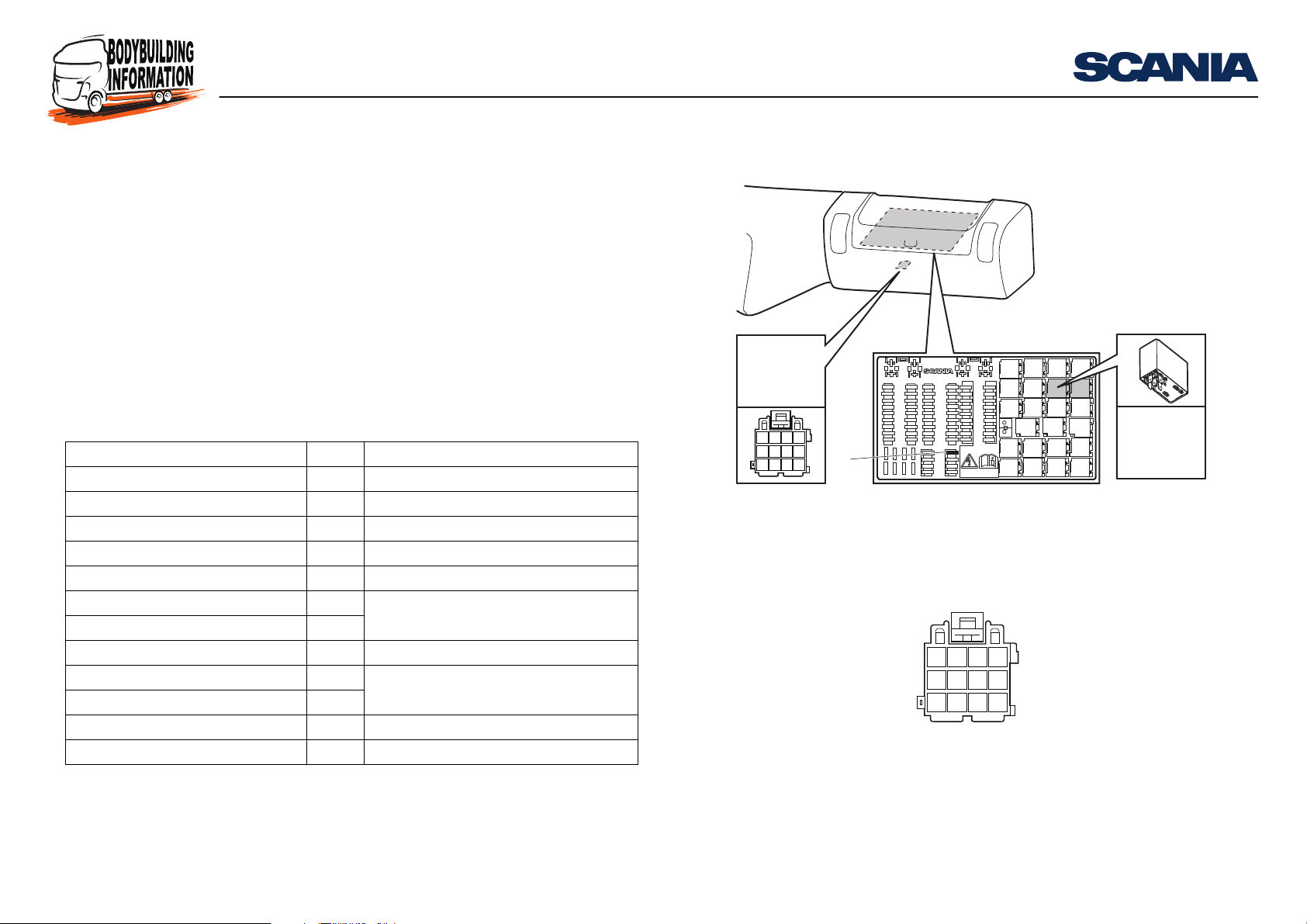
Pin numbering on connector C137
1. Fuse for RTG
E51: Relay socket for RTG connection
Connection to RTG
Connector C137
Vehicle production period
Production site Chassis serial number
2009-02-09 -
Södertälje 2 046 610 -
Zwolle 5 225 592 -
Angers 9 141 661 -
São Bernardo do Campo 3 644 908 -
Signal Pin Comments
Connection 15 (Ubat) 10
Connection 30 (24 V) 12
Connection 31 (24 V ground) 1
CAN low 9
CAN high 6
CAN low 5
CAN high 8
Connection 15R (Ubat) 11
12 V voltage 3
12 V ground 4
Reserved 2
Reserved 7
Not supported by Scania
Only if vehicle is equipped with a 12 V
voltage converter
C137
Connection to RTG
E51
1
14710
25811
369
12
307 952
RTG
307 953
11:90-02 Issue 7 en-GB 7 (92)
© Scania CV AB 2017, Sweden
Page 8
CAN interface for FMS
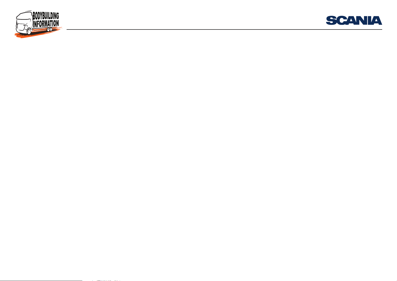
Connector C471
Vehicle production period
Production site Chassis serial number
- 2009-02-08
Södertälje - 2 046 609
Zwolle - 5 225 591
Angers - 9 141 660
São Bernardo do Campo - 3 644 907
Connect CAN high to connector C471, pin 2, and CAN low to connector C471, pin 1.
Connection to RTG
11:90-02 Issue 7 en-GB 8 (92)
© Scania CV AB 2017, Sweden
Page 9
CAN interface for FMS
< 30 m
> 0.1 m
< 3 m
12
RTG
C137
ECU X
ECU Z ECU Y
307 950
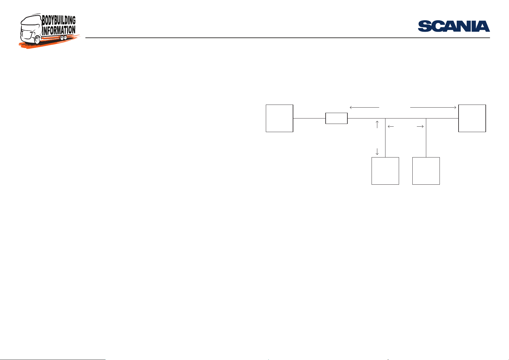
1. RTG control unit with termination resistor
2. FMS control unit in the bodywork with termination resistor
Topology
The topology is primarily a bus cable with the nodes connected to the CAN bus with
at least 0.1 metres between each node.
• The length of the cables should not exceed 30 metres (main cable) between the
connector in the truck and the control unit with the other termination resistor.
• If more than one control unit is connected, the length of the cables between the
main cable and control unit should not exceed 3 metres.
• The cables should be as short as possible to minimise the effect of electromagnetic interference.
• The number of control units in the external FMS network should not exceed 9.
The figure shows the principle of the external FMS network topology.
Connection to RTG
11:90-02 Issue 7 en-GB 9 (92)
© Scania CV AB 2017, Sweden
Page 10
CAN interface for FMS
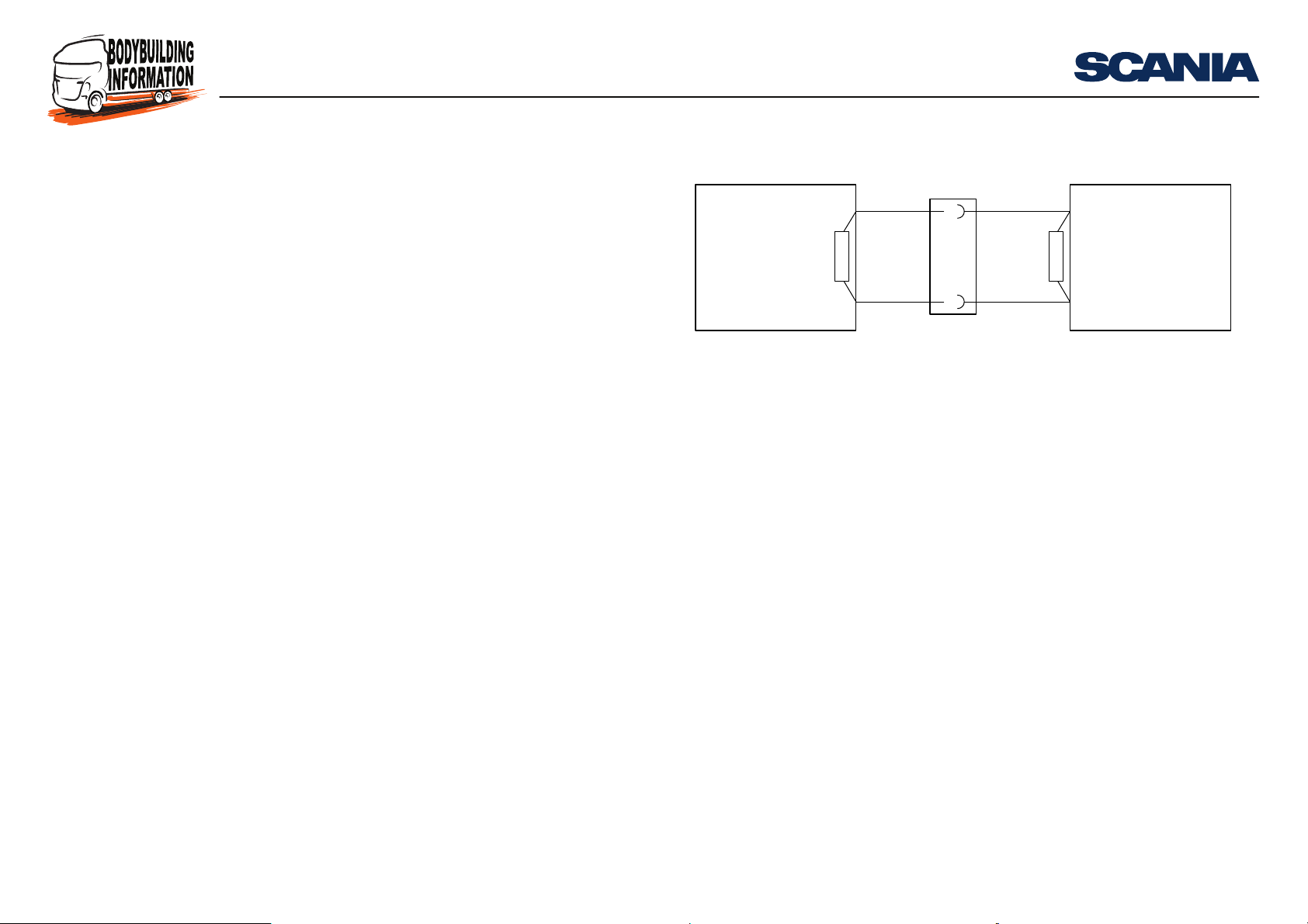
1. RTG with internal termination resistor
2. Connectors that constitute an interface for bodybuilders
3. Termination resistor fitted in the control unit connector
Termination resistors
Termination resistors
The CAN bus cable must be terminated using a 120 Ohm resistor at each end in accordance with SAE J1939-15 Physical Layer.
Depending on the other control units connected to the CAN bus, there must be a 120
Ohm termination resistor in the control unit which is connected to the FMS interface
for bodybuilders.
If the control unit is not equipped with an internal termination resistor, an external
termination resistor must be connected as close to the control unit as possible (see
illustration).
CAN High
CAN Low
1
ECU X RTG
R
CAN High
CAN Low
3
310 812
6
R
C137
9
2
11:90-02 Issue 7 en-GB 10 (92)
© Scania CV AB 2017, Sweden
Page 11
CAN interface for FMS
Termination of an external CAN bus
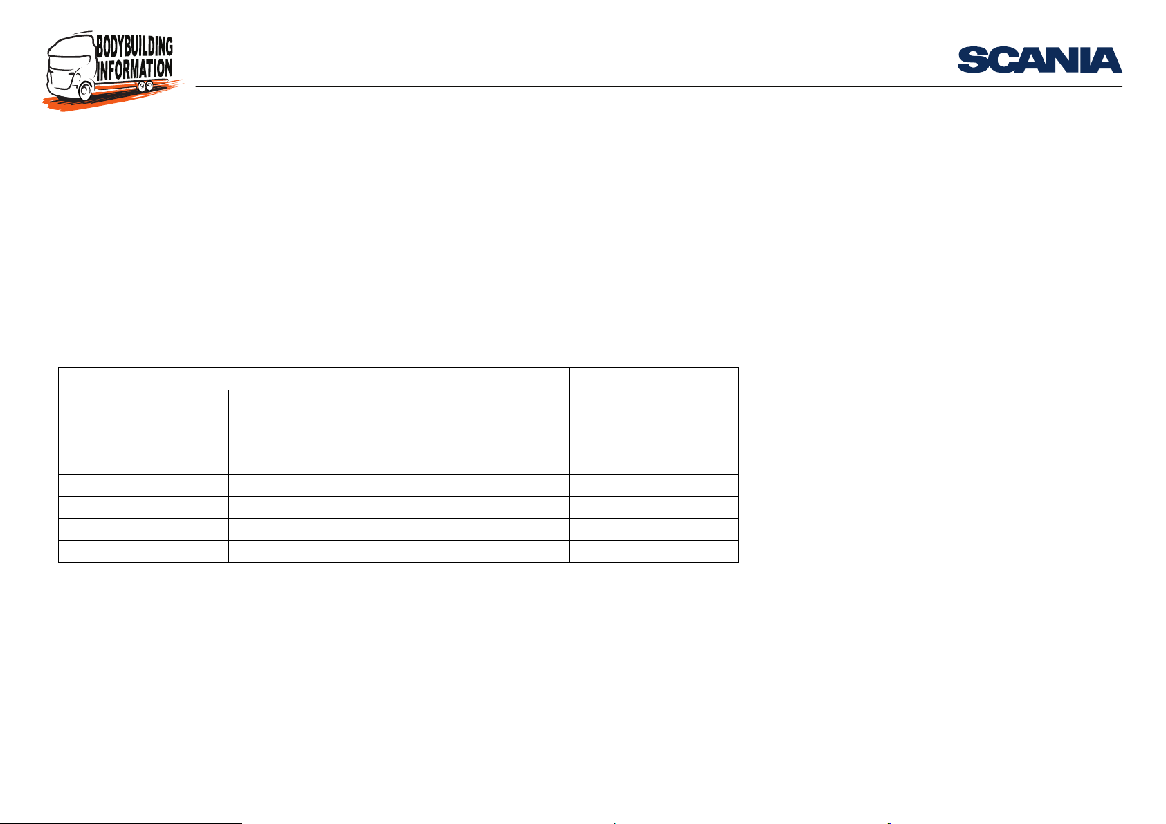
So that CAN communication can work without interference, there must be a 120
Ohm termination resistor at each end of the CAN bus. Check that there is a termination resistor at each end of the CAN bus using a multimeter. The resistance should
be 60 Ohm (two 120 Ohm resistors connected in parallel).
A number of different systems can be connected to the cable harness of the external
CAN bus. Certain systems have a built-in termination resistor and others are unterminated.
The table shows when there is to be a termination resistor in connector C137 or in the
control unit connected to C137.
Systems in the vehicle Termination resistor in
DTCO Scania Communicator
C200
No No Yes Yes
Yes No Yes No
Yes Yes Yes No
No Yes Yes Yes
Yes No No Yes
Yes Yes No Yes
RTG
Termination resistors
the control unit connect-
ed to C137
11:90-02 Issue 7 en-GB 11 (92)
© Scania CV AB 2017, Sweden
Page 12
CAN interface for FMS
Fault validation of communication (TimeOut)
Avoid CAN communication when the starter key is in the lock or radio positions.
Also avoid CAN communication during the start sequence of the control units connected to the external CAN bus.
During normal operation, when the starter key is in the drive position, a message
should not be validated as missed (time-out) until at least 5 times the message period
time. A longer fault validation time is permitted.
During the engine start sequence, when the starter motor is turning, the supply voltage can be extremely low. Because of this, communication from the RTG control
unit cannot be guaranteed during this sequence. For this reason, no fault codes related
to CAN communication with the RTG control unit should be set when the system
voltage is under 18 V.
When the starter key is turned to the drive position, the RTG control unit starts sending messages within 10,000 ms. A message sent from the FMS control unit cannot
be considered missed until after 10,000 ms + 5 x the message period time. Example:
If a message has a period time of 100 ms it cannot be considered missed until after
10,000 + 5 x 100 = 10,500 ms. Longer fault validation times are permitted.
Fault validation of communication (Time-Out)
11:90-02 Issue 7 en-GB 12 (92)
© Scania CV AB 2017, Sweden
Page 13
CAN interface for FMS
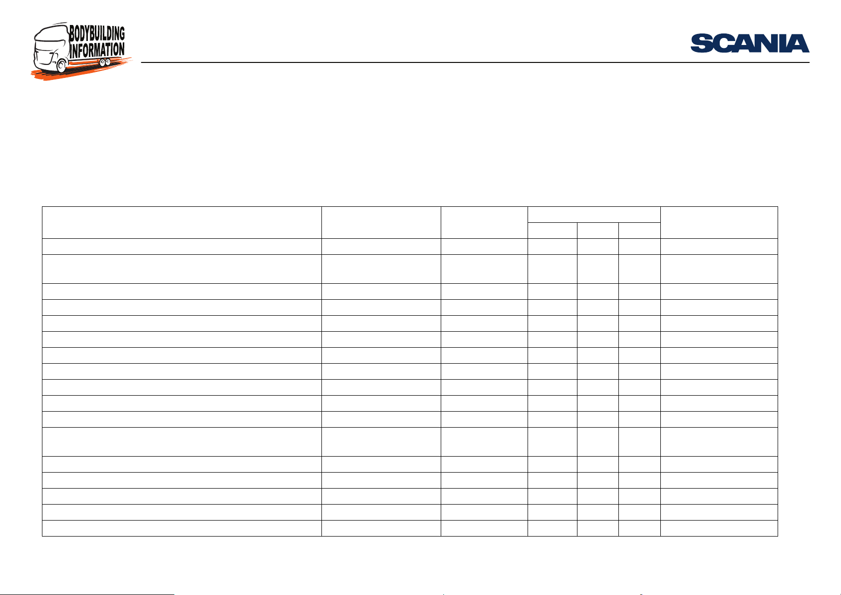
Summary of CAN messages
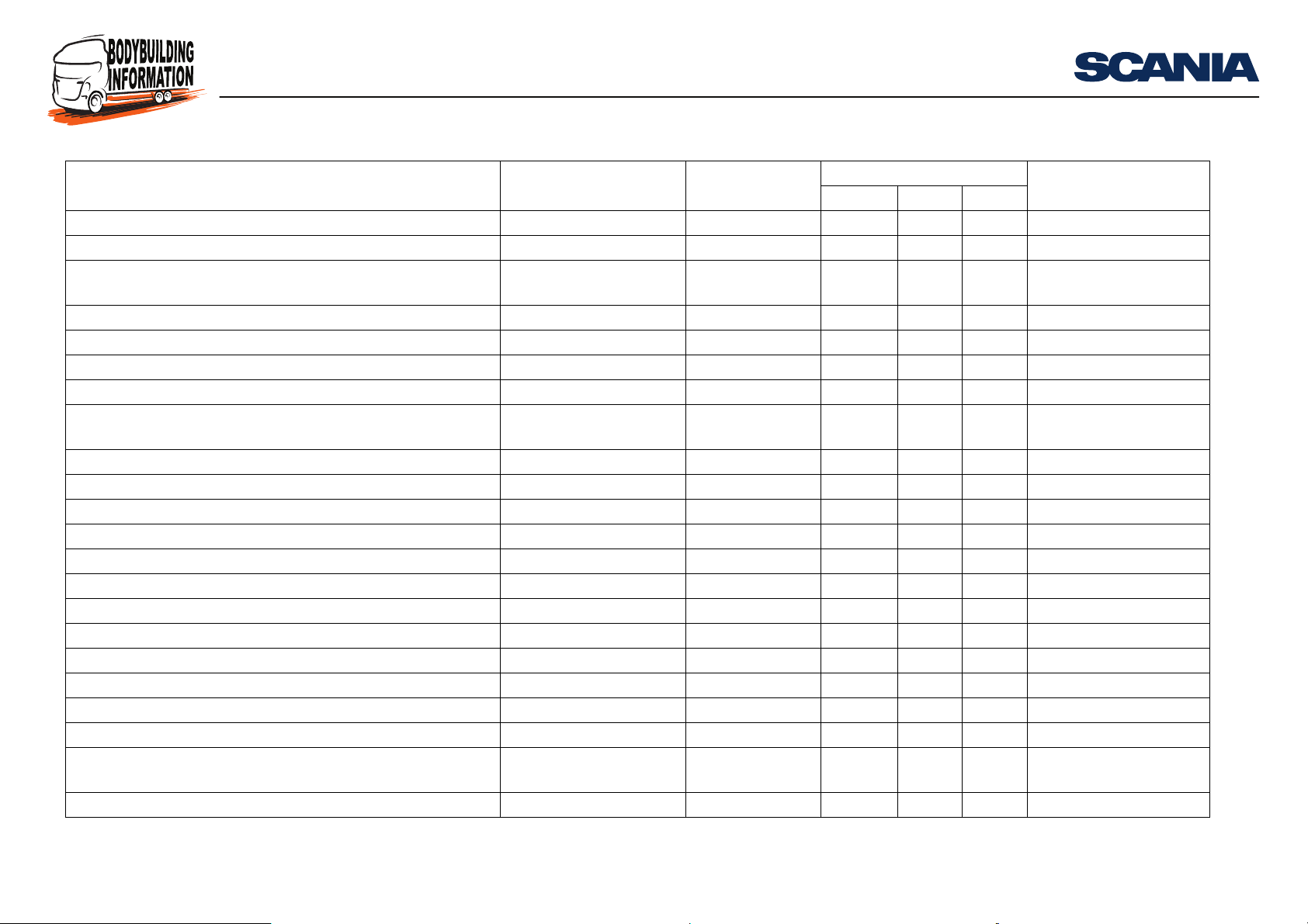
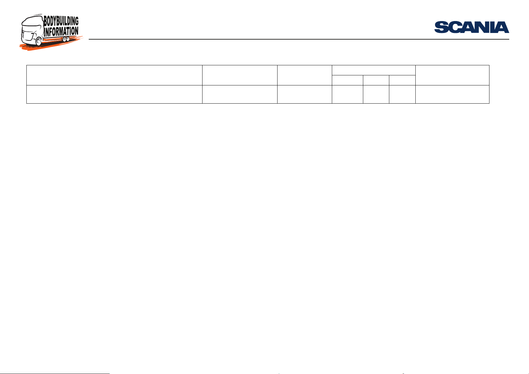
Summary of CAN messages
The following is a summary of the messages supported by the CAN interface for
FMS.
CAN messages which are sent to the external CAN bus from the RTG interface
Message sent from vehicle Identifier (Hex) Specification FMS standard Scania’s FMS interface
01.00 02.00 03.00
Air Pressure Supply 18 FE AE 30 SAEJ1939-71 X X
Aftertreatment 1 Diesel Exhaust Fluid Tank 1 Information:
AT1T1I
Alarm Status Proprietary
Ambient Conditions - K 18 FE F5 27 SAEJ1939-71 X X X
Cab Illumination Message - ICL 18 D0 FF 17 SAEJ1939-71 X
Combination Vehicle Weight: CVW 18 FE 70 25 SAEJ1939-71 X X
Coordinator General Information - K 0C FF B0 27 Scania X
Crash Occurred - AB 18 FF FD 64 Scania X
Cruise Control/Vehicle Speed 18 FE F1 00 SAEJ1939-71 X X X X
CUV Information - V 18 FF B1 1E Scania X
Dash Display - K 18 FE FC 27 SAEJ1939-71 X X X X
Driver’s Identification (DI_cyclic) - FMS (transmitted using
BAM)
EBC2 Wheel Speed Proprietary 0C FF 19 0B Scania X
Electronic Brake Controller 1 (EBC1) - A 18 F0 01 0B SAEJ1939-71 X
Electronic Engine Controller 1 (EEC1) - E 0C F0 04 00 SAEJ1939-71 X X X X
Electronic Engine Controller 2 (EEC2) - E 0C F0 03 00 SAEJ1939-71 X X X X
Electronic Retarder Controller1 (ERC1) - RD 18 F0 00 10 SAEJ1939-71 X
a
18 FE 56 25 SAEJ1939-71 X X
18 FF B4 1D Scania X
18 EC FF 25/18 EB FF 25 SAEJ1939-71 X X X
(RTG)
11:90-02 Issue 7 en-GB 13 (92)
© Scania CV AB 2017, Sweden
Page 14
CAN interface for FMS
Summary of CAN messages
Message sent from vehicle Identifier (Hex) Specification FMS standard Scania’s FMS interface
01.00 02.00 03.00
Electronic Retarder Controller1 (ERC1) - REX 18 F0 00 29 SAEJ1939-71 X
Electronic Transmission Controller 2 (ETC2) -T 18 F0 05 03 SAEJ1939-71 X
Engine Configuration (EngineConfig) - E (transmitted using
18 EC FF 00/18 EB FF 00 SAEJ1939-71 X
BAM)
Engine Fluid Level/Pressure 1 - K 18 FE EF 27 SAEJ1939-71 X
Engine Hours, Revolutions - E 18 FE E5 00 SAEJ1939-71 X X X X
Engine Temperature 1 - E 18 FE EE 00 SAEJ1939-71 X X X X
Error Message - FMS 18FFFF25 Scania X
FMS-standard Interface Identity/Capabilities (FMS Std Inter-
1C FD D1 25 SAEJ1939-71 X X X X
face) - FMS
FMS Tell Tale Status: FMS1 18 FD 7D 17 SAEJ1939-71 X X
Fuel Consumption - E 18 FE E9 00 SAEJ1939-71 X X X X
Fuel Economy - E 18 FE F2 00 SAEJ1939-71 X X X
General Purpose Message 1 - E 18 FF 60 00 Scania X
High Resolution Fuel Consumption (Liquid) (HRLFC) - FMS 18 FD 09 25 SAEJ1939-71 X
High Resolution Vehicle Distance - TCO 18 FE C1 EE SAEJ1939-71 X X X X
Inlet/Exhaust Conditions 1 - E 18 FE F6 00 SAEJ1939-71 X
PTO Drive Engagement
b
N/A SAEJ1939-71 X X
PTO Information Proprietary - K 18 FF 90 27 Scania X
Service Information (ServiceInformation) - FMS 18FEC025 SAEJ1939-71 X X X X
Tachograph - TCO1 0C FE 6C EE SAEJ1939-71 X X X X
Time/Date (TimeDate) - ICL 18 FE E6 17 SAEJ1939-71 X
Vehicle Identification (VehicleId) - FMS (transmitted using
18ECFF25/18EBFF25 SAEJ1939-71 X X X X
BAM)
Vehicle Weight (Vehicle Weight) - FMS 18 FE EA 25 SAEJ1939-71 X X X X
(RTG)
11:90-02 Issue 7 en-GB 14 (92)
© Scania CV AB 2017, Sweden
Page 15
CAN interface for FMS
Summary of CAN messages
Message sent from vehicle Identifier (Hex) Specification FMS standard Scania’s FMS interface
(RTG)
Wheel Brake Lining Remaining Information (EBC4WheelBrakeLiningRemainingInf) - A
a. Only sent if the vehicle has an alarm (LAS).
b. According to the standard, either PTO Drive Engagement or CCVS is sent. Scania sends CCVS.
c. Only sent if the vehicle is equipped with EBS.
c
1C FE AC 0B SAEJ1939-71 X
01.00 02.00 03.00
11:90-02 Issue 7 en-GB 15 (92)
© Scania CV AB 2017, Sweden
Page 16
CAN interface for FMS
Detailed description of CAN messages
The following tables use the concepts below:
• Not defined: Not defined in SAE J1939
• Not used: Defined in SAE J1939 but not used by Scania
For the contents of messages with parameter group numbers (PGN) specified by Scania:
• Not defined: Not defined by Scania
Detailed description of CAN messages
11:90-02 Issue 7 en-GB 16 (92)
© Scania CV AB 2017, Sweden
Page 17
CAN interface for FMS
Detailed description of CAN messages
Air Pressure Supply - APS
Identifier: 18FEAE30
Transmission interval: 1,000 ms
Byte Bit Length Explanation State Resolution Limits Note
1..2 Not defined
3 1 8 Service Brake Air Pressure, Circuit 1 8 kPa/Bit 0-2,000
Error FE
Not available FF
4 1 8 Service Brake Air Pressure, Circuit 2 8 kPa/Bit 0-2,000 Rear Circuit
Error FE
Not available FF
5..8 Not defined
11:90-02 Issue 7 en-GB 17 (92)
© Scania CV AB 2017, Sweden
Page 18
CAN interface for FMS
Detailed description of CAN messages
Aftertreatment 1 Diesel Exhaust Fluid Tank 1 Information: AT1T1I
Identifier: 18FE5625
Transmission interval: 1,000 ms
Byte Bit Length Explanation State Resolution Limits Note
1 1 8 Aftertreatment 1 Diesel Exhaust Fluid Tank 1 Level 0.4% 0-100%
Error FE
Not available FF
2..8 Not used
11:90-02 Issue 7 en-GB 18 (92)
© Scania CV AB 2017, Sweden
Page 19
CAN interface for FMS
Detailed description of CAN messages
Alarm Status Propietary - AL
Identifier: 18 FF B4 1D
Transmission interval: 1,000 ms.
Byte Bit Length Explanation State Resolution Limits Note
114Alarm status
Alarm unset 0000
Alarm set 0001
Alarm triggered 0010
Silent alarm triggered 0011
Alarm set perimeter 0100
Ferry mode 0101
Alarm unset with XPDR failed 0110
Alarm unset with XPDR successed 0111
Work alert 1000
Alarm test 1001
Alarm passive set 1010
Not defined 1100..1101
Reserved 1110
Don't care/take no action 1111
5 4 Not defined
2..8 Not defined
11:90-02 Issue 7 en-GB 19 (92)
© Scania CV AB 2017, Sweden
Page 20
CAN interface for FMS
Detailed description of CAN messages
Ambient Conditions
Identifier: 18 FE F5 27
Transmission interval: 1,000 ms
Always sent from BWS.
Byte Bit Length Explanation State Resolution Limits Note
1 1 8 Barometric pressure 0.5 kPa/bit 0 to 125 kPa
Error indicator FE
Not available FF
2 Not used
4 1 16 Ambient air temperature 0.03125 °C/bit -273 to +1 735.0 °C
Error indicator FExx
Not available FFxx
6..8 Not used
11:90-02 Issue 7 en-GB 20 (92)
© Scania CV AB 2017, Sweden
Page 21
CAN interface for FMS
Detailed description of CAN messages
Cab Illumination Message
Identifier: 18 D0 FF 17
Transmission interval: 100 ms
Always sent from BWS.
Byte Bit Length Explanation State Resolution Limits Note
1 1 8 Requested illumination percentage 0.4% 0 to 100%
Error FEh
Not available FFh
2..8 Not defined
11:90-02 Issue 7 en-GB 21 (92)
© Scania CV AB 2017, Sweden
Page 22
CAN interface for FMS
Detailed description of CAN messages
Combination Vehicle Weight: CVW
Identifier: 18FE7025
Transmission interval: 10,000 ms
Byte Bit Length Explanation State Resolution Limits Note
1..2 Not used
3 1 16 Gross Combination Vehicle Weight 10 kg 0-642550 kg C
Error FE
Not available FF
3..8 Not used
C: This information shall NOT be used for any calculation that needs an exact value,
this parameter only shows un-laden/semi-laden/laden vehicle.
11:90-02 Issue 7 en-GB 22 (92)
© Scania CV AB 2017, Sweden
Page 23
CAN interface for FMS
Coordinator General Information
Identifier: 0C FF B0 27
Detailed description of CAN messages
Transmission interval: 200 ms
1
Always sent from BWS.
Byte Bit Length Explanation State Resolution Limits Note
1..3 Not defined
4 1..2 Not defined
3 2 Engine stop switch
Engine stop switch not activated 00
Engine stop switch activated 01
Error 10
Not available 11
5 2 Not defined
7 2 0,8 bar parking brake
0,8 bar parking brake not set 00
0,8 bar parking brake set 01
Error indicator 10
Not available or not installed 11
5 1..6 Not defined
7 2 Gearbox in reverse A
Gearbox not in reverse 00
Gearbox in reverse 01
Error 10
1. The normal transmission interval is 200 ms. If certain parameters are modified, the transmission
interval is 10 ms.
11:90-02 Issue 7 en-GB 23 (92)
© Scania CV AB 2017, Sweden
Page 24
CAN interface for FMS
Detailed description of CAN messages
Byte Bit Length Explanation State Resolution Limits Note
Not available 11
6..8 Not defined
A: Information is taken from ETC2 on all gearboxes apart from manual gearboxes
without a torque converter.
11:90-02 Issue 7 en-GB 24 (92)
© Scania CV AB 2017, Sweden
Page 25
CAN interface for FMS
Detailed description of CAN messages
Crash Occured
Identifier: 18 FF FD 64
Transmission interval: 1,000 ms
Only sent from BWS if Crash Safety System (CSS) is installed.
Byte Bit Length Explanation State Resolution Limits Note
1..8 Not used
11:90-02 Issue 7 en-GB 25 (92)
© Scania CV AB 2017, Sweden
Page 26

CAN interface for FMS
Detailed description of CAN messages
Cruise Control/Vehicle Speed
Identifier: 18 FE F1 00
Transmission interval: 100 ms
Always sent from BWS.
Byte Bit Length Explanation State Resolution Limits Note
1 1..2 Not used
3 2 Parking brake switch A
Parking brake not set 00
Parking brake set 01
Error indicator 10
Not available or not installed 11
5..6 Not used
7..8 Not defined
2 1 16 Wheel-based vehicle speed 1/256 km/h per bit 0 to 251 km/h
Error indicator FExx
Not available FFxx
4 1 2 Cruise control active
Cruise control switched off 00
Cruise control switched on 01
Error indicator 10
Not available or not installed 11
32Brake switch
Brake pedal released 00
Brake pedal depressed 01
Error indicator 10
11:90-02 Issue 7 en-GB 26 (92)
© Scania CV AB 2017, Sweden
Page 27
CAN interface for FMS
Detailed description of CAN messages
Byte Bit Length Explanation State Resolution Limits Note
Not available or not installed 11
7 2 Clutch switch
Clutch pedal released 00
Clutch pedal depressed 01
Error indicator 10
Not available or not installed 11
5 1 2 Cruise control set switch
Cruise control activator not in the position "set" 00
Cruise control activator in position "set" 01
Error indicator 10
Not available or not installed 11
3 2 Cruise control coast (decelerate) switch
Cruise control activator not in the position "coast" 00
Cruise control activator in position "coast" 01
Error indicator 10
Not available or not installed 11
5 2 Cruise control resume switch
Cruise control activator not in the position "resume" 00
Cruise control activator in position "resume" 01
Error indicator 10
Not available or not installed 11
7 2 Cruise control accelerate switch
Cruise control activator not in the position "accelerate" 00
Cruise control activator in position "accelerate" 01
Error indicator 10
Not available or not installed 11
11:90-02 Issue 7 en-GB 27 (92)
© Scania CV AB 2017, Sweden
Page 28
CAN interface for FMS
Detailed description of CAN messages
Byte Bit Length Explanation State Resolution Limits Note
6 1 8 Cruise control set speed 1 km/h 0 to 250 km/h
Error indicator FEh
Not available FEh
7 1 5 PTO State 0 to 31
Off/disabled 00000
Hold 00001
Remote Hold 00010
Standby 00011
Remote standby 00100
Set 00101 B
Decelerate/coast 00110
Resume 00111
Accelerate 01000
Accelerate override 01001
Preprogrammed set speed 1 01010
Preprogrammed set speed 2 01011
Preprogrammed set speed 3 01100
Preprogrammed set speed 4 01101
Preprogrammed set speed 5 01110
Preprogrammed set speed 6 01111
Preprogrammed set speed 7 10000
Preprogrammed set speed 8 10001
Not available 11111
6 3 Cruise control states
Off/disabled 000
Hold 001
11:90-02 Issue 7 en-GB 28 (92)
© Scania CV AB 2017, Sweden
Page 29
CAN interface for FMS
Detailed description of CAN messages
Byte Bit Length Explanation State Resolution Limits Note
Accelerate 010
Decelerate/coast 011
Resume 100
Set 101
Accelerator override 110
Not available 111
8 Not used
A: Information from a pressure sensor on the parking brake lever. The “Parking
brake not set” parameter is sent when the pressure is more than 6 bar.
B: Version differs from the FMS standard. PTO state 1 in position Set is shown as
0001 instead of 00101 for the following vehicles.
Vehicle production period
Production site Chassis serial number
- 2008-01-22
Södertälje - 2 034 902
Zwolle - 5 196 997
Angers - 9 129 358
São Bernardo do Campo - 3 621 168
11:90-02 Issue 7 en-GB 29 (92)
© Scania CV AB 2017, Sweden
Page 30
CAN interface for FMS
Detailed description of CAN messages
CUV information - V
Identifier: 18 FF B1 1E
Transmission interval: 1,000 ms
Always sent from BWS.
The message should be sent out once every 1,000 ms and when any of the parameters
changes, but not more rapidly than 20 ms.
Byte Bit Length Explanation State Resolution Limits Note
1 1 2 Main beam intended A
Off 00
On 01
Error 10
Not available 11
3 2 Dipped beam intended
Off 00
On 01
Error 10
Not available 11
5..8 Not defined
2 1 2 Front fog lamp intended
Off 00
On 01
Error 10
Not available 11
3 2 Rear fog lamp intended
Off 00
11:90-02 Issue 7 en-GB 30 (92)
© Scania CV AB 2017, Sweden
Page 31
CAN interface for FMS
Detailed description of CAN messages
Byte Bit Length Explanation State Resolution Limits Note
On 01
Error 10
Not available 11
5 2 Reversing lamp intended
Off 00
On 01
Error 10
Not available 11
7 2 Stop lamp intended
Off 00
On 01
Error 10
Not available 11
3 1 2 Wiper intended
Off 00
On 01
Error 10
Not available 11
3..4 Not defined
5 2 Direction indicator lamp status truck left
Off 00
On 01
Error 10
Not available 11
7 2 Direction indicator lamp status truck right
Off 00
11:90-02 Issue 7 en-GB 31 (92)
© Scania CV AB 2017, Sweden
Page 32
CAN interface for FMS
Detailed description of CAN messages
Byte Bit Length Explanation State Resolution Limits Note
On 01
Error 10
Not available 11
4 1 2 Direction indicator lamp status trailer left
Off 00
On 01
Error 10
Not available 11
3 2 Direction indicator lamp status trailer right
Off 00
On 01
Error 10
Not available 11
5 2 Direction indicator lever status
Off 00
On 01
Error 10
Not available 11 B
7 2 Horn intended
Off 00
On 01
Error 10
Not available 11
5..6 Not defined
7 1 2 Work light toggle switch
Off 00
11:90-02 Issue 7 en-GB 32 (92)
© Scania CV AB 2017, Sweden
Page 33
CAN interface for FMS
Detailed description of CAN messages
Byte Bit Length Explanation State Resolution Limits Note
On 01
Error 10
Not available 11
3 2 Work light output status
Off 00
On 01
Error 10
Not available 11
5258
Off 00
On 01
Error 10
Not available 11
7..8 Not defined
8 1 4 Not defined
5 2 Parking lights
Switch not in parking lights position 00
Switch in parking lights position 01
Error 10
Not available 11
7 2 Driving lights
Switch not in driving lights position 00
Switch in driving lights position 01
Error 10
Not available 11
11:90-02 Issue 7 en-GB 33 (92)
© Scania CV AB 2017, Sweden
Page 34
CAN interface for FMS
A: Sent as ON if any of the lamps is activated.
B: Sent if the direction indicator lever has a normal position or if a fault has been detected.
Detailed description of CAN messages
11:90-02 Issue 7 en-GB 34 (92)
© Scania CV AB 2017, Sweden
Page 35
CAN interface for FMS
Detailed description of CAN messages
Dash Display
Identifier: 18 FE FC 27
Transmission interval: 1,000 ms
Always sent from BWS.
Byte Bit Length Explanation State Resolution Limits Note
1 Not used
2 1 8 Fuel level 0.4%/bit 0 to 100%
Error FEh
Not available FFh
3..6 Not used
7..8 Not defined
11:90-02 Issue 7 en-GB 35 (92)
© Scania CV AB 2017, Sweden
Page 36
CAN interface for FMS
Detailed description of CAN messages
Driver’s Identification (DI_cyclic)
Identifier: 18 EC FF 25/18 EB FF 25
Transmission interval: 10,000 ms
Sent as BAM/TP.DT.
Parameter group numbers: FE6B (65131 decimal)
Byte Bit Length Explanation State Resolution Limits Note
1 1 8 Driver 1 Identifier (Driver1Identifier) 1 A
2 1 8 Delimiter (Delimiter) 1 B
3 1 8 Driver 2 Identifier (Driver2Identifier) 1 C
4 1 8 Delimiter (Delimiter) 1 D
A: Length m
B: Starts at byte m
C: Length n, starts at byte m+1
D: Starts at byte m+1+n
11:90-02 Issue 7 en-GB 36 (92)
© Scania CV AB 2017, Sweden
Page 37
CAN interface for FMS
Note:
Detailed description of CAN messages
EBC2 Wheel Speed Proprietary
Identifier: 0C FF 19 0B
Transmission interval: 50 ms
The message is defined in the same way as J1939 PGN (Wheel Speed Information)
but has a higher updating frequency.
Byte Bit Length Explanation State Resolution Limits Note
1 1 16 Mean front axle speed 1/256 kph 251 kph
Error indicator FExx
Not available FFxx
3 1 8 Relative speed front axle left 1/16 kph -7.8125 to +7.8125 kph
Error indicator FE
Not available FF
4 1 8 Relative speed front axle right 1/16 kph -7.8125 to +7.8125 kph
Error indicator FE
Not available FF
5 1 8 Relative speed drive axle left 1/16 kph -7.8125 to +7.8125 kph
Error indicator FE
Not available FF
6 1 8 Relative speed drive axle right 1/16 kph -7.8125 to +7.8125 kph
Error indicator FE
Not available FF
7 1 8 Relative speed third axle left 1/16 kph -7.8125 to +7.8125 kph
Error indicator FE
11:90-02 Issue 7 en-GB 37 (92)
© Scania CV AB 2017, Sweden
Page 38
CAN interface for FMS
Detailed description of CAN messages
Byte Bit Length Explanation State Resolution Limits Note
Not available FF
8 1 8 Relative Speed Third Axle Right -7.8125 to +7.8125 kph
Error indicator FE
Not available FF
11:90-02 Issue 7 en-GB 38 (92)
© Scania CV AB 2017, Sweden
Page 39
CAN interface for FMS
Detailed description of CAN messages
Electronic Brake Controller 1
Identifier: 18 F0 01 0B
Transmission interval: 100 ms and if there is a change in the condition of the EBS
brake switch parameter.
Always sent from BWS.
When no ABS or EBS system is installed, only the parameter ’Brake pedal position’is sent.
Byte Bit Length Explanation State Resolution Limits Note
1 1 2 ASR engine control active
ASR engine control passive but installed 00
ASR engine control active 01
Not available 11 A
3 2 ASR brake control active
ASR brake control passive but installed 00
ASR brake control active 01
Not available 11 A
5 2 Anti-lock braking (ABS) active
ABS passive but installed 00
ABS active 01
Not available 11
7 2 EBS brake switch
Brake pedal is not being pressed 00
Brake pedal is being pressed 01
Error 10
11:90-02 Issue 7 en-GB 39 (92)
© Scania CV AB 2017, Sweden
Page 40
CAN interface for FMS
Detailed description of CAN messages
Byte Bit Length Explanation State Resolution Limits Note
Not available 11
2 1 8 Brake pedal position 0.4%/bit 0 to 100%
Error indicator FE
Not available FF
3 1 2 ABS offroad switch B
ABS offroad switch passive 00
ABS offroad switch active 01
Not available 10 C
3 2 ASR offroad switch B
ASR offroad switch passive 00
ASR offroad switch active 01
Not available 10
5 2 ASR hill holder switch
ASR hill holder switch passive 00
ASR hill holder switch active 01
Error 10
Not available 11
7 2 Traction control override switch
Off 00
On 01
Error 10
Not available 11
4 1 2 Accelerator interlock switch
Off 00
On 01
Error 10
11:90-02 Issue 7 en-GB 40 (92)
© Scania CV AB 2017, Sweden
Page 41
CAN interface for FMS
Detailed description of CAN messages
Byte Bit Length Explanation State Resolution Limits Note
Not available 11
3 2 Engine derate switch
Off 00
On 01
Error 10
Not available 11
5 2 Auxiliary engine shutdown switch
Off 00
On 01
Error 10
Not available 11
7 2 Remote accelerator enable switch
Off 00
On 01
Error 10
Not available 11
5 1 8 Engine retarder selection
Error 10
Not available 11
6 1 2 ABS fully operational
ABS not fully operational 00
ABS fully operational 01
3 2 EBS red warning state D
Off 00
On 01
5 2 ABS/EBS amber warning state
11:90-02 Issue 7 en-GB 41 (92)
© Scania CV AB 2017, Sweden
Page 42
CAN interface for FMS
Detailed description of CAN messages
Byte Bit Length Explanation State Resolution Limits Note
Off 00
On 01
Take no action 11
7 2 ATC/ASR Lamp state (Powered vehicle)
Off 00
On 01
Reserved 10
Take no action 11
7 1 8 Source adress of controlling device for brake control 0 to 250 E
Reserved FEh
Take no action FFh
8 1..2 Not defined
3 2 Halt brake switch
Halt brake switch passive 00
Halt brake switch active 01
Error 10
Not available 11
52Trailer ABS status
Trlr ABS Stts Infrmtn Avlbl Bt Nt Actv 00
Trailer ABS active 01
Reserved 10
Trlr ABS Stts Infrmtn Nt Avlbl Prmtr N 11
7 2 Tractor mounted trailer ABS warning signal
Off 00
On 01
Reserved 10
11:90-02 Issue 7 en-GB 42 (92)
© Scania CV AB 2017, Sweden
Page 43
CAN interface for FMS
Detailed description of CAN messages
Byte Bit Length Explanation State Resolution Limits Note
Take no action 11
A: Only sent when ASR is not installed.
B: Describes the function, not the switch position. 00 when the function is inactive,
01 when it is active.
C: Only sent when ABS off-road is not installed.
D: Only sent if EBS is installed.
E: For ACS use.
11:90-02 Issue 7 en-GB 43 (92)
© Scania CV AB 2017, Sweden
Page 44
CAN interface for FMS
Detailed description of CAN messages
Electronic Engine Controller 1
Identifier: 0C F0 04 00
Transmission interval: 20 ms
Always sent from BWS.
Byte Bit Length Explanation State Resolution Limits Note
1 1 4 Engine and retarder torque mode A
Low idle governor 0000
Accelerator pedal 0001
Cruise control 0010
PTO governor 0011
Road speed governing 0100
ASR control 0101
Transmission control 0110
Not used 0111
Torque limiting 1000
High speed governor 1001
Not used 1010
Not used 1011
Not defined 1100
Not used 1101
Other 1110
Not available 1111
5 4 Actual engine - percent torque high resolution 0.125 0 to 0.875% B
Not available 1000
Not available 1001
11:90-02 Issue 7 en-GB 44 (92)
© Scania CV AB 2017, Sweden
Page 45
CAN interface for FMS
Detailed description of CAN messages
Byte Bit Length Explanation State Resolution Limits Note
Not available 1010
Not available 1011
Not available 1100
Not available 1101
Not available 1110
Not available 1111
2 1 8 Drivers demand engine - percent torque 1% -125% to +125%
Error indicator FEh
Not available FFh
3 1 8 Actual engine - percent torque percent torque: 1% -125% - offset
Error indicator FEh
Not available FFh
4 1 16 Engine speed 0.125 r/min 0 to 8 031.875 r/min
Error indicator FExxh
Not available FFxxh
6 1 8 Source address of controlling device for engine control 1 0 to 250
Error FE
Take no action FF
7 1 4 Engine starter mode 1 0 to 15
Start not rqed 0000
Starter active gear not engaged 0001
Starter active gear engaged 0010
Strt fnshd strtr nt actv aftr hvng bn a 0011
Strtr inhbtd d to eng already running 0100
Strtr inhbtd d to eng nt ready for start 0101
Strtr inhbtd d to drv in enggd othr trns 0110
11:90-02 Issue 7 en-GB 45 (92)
© Scania CV AB 2017, Sweden
Page 46
CAN interface for FMS
Detailed description of CAN messages
Byte Bit Length Explanation State Resolution Limits Note
Strtr inhbtd d to active immobilizer 0111
Strtr inhbtd due to starter overtemp 1000
1011 reserved 1001
Starter inhibited reason unknown 1100
Error 1110
Not available 1111
5..8 Not defined
8 1 8 Engine demand - percent torque 1 -125 to 125%
Error FE
Not available FF
A: The message Not available is only sent when the engine is not running.
B: Bit pattern 1000-1111 = Not available.
11:90-02 Issue 7 en-GB 46 (92)
© Scania CV AB 2017, Sweden
Page 47
CAN interface for FMS
Detailed description of CAN messages
Electronic Engine Controller 2
Identifier: 0C F0 03 00
Transmission interval: 50 ms
Always sent from BWS.
Byte Bit Length Explanation State Resolution Limits Note
1 1 2 Accelerator pedal low idle switch
Accelerator pedal not in low idle condition 00
Accelerator pedal in low idle condition 01
Error indicator 10
Not available 11
3 2 Accelerator pedal kickdown switch
Kickdown passive 00
Kickdown active 01
Error indicator 10
Not available 11
5 2 Road speed limit status
Active 00
Not active 01
7 2 Accelerator pedal 2 low idle switch
Accl pedal not in low idle condition 00
Accel pedal in low idle condition 01
Error 10
Not available 11
2 1 8 Accelerator pedal position 0.4% 0 to 100%
Error indicator FE
11:90-02 Issue 7 en-GB 47 (92)
© Scania CV AB 2017, Sweden
Page 48
CAN interface for FMS
Detailed description of CAN messages
Byte Bit Length Explanation State Resolution Limits Note
Not available FF
3 1 8 Percent load at current speed 1% 0 to 125%
Error indicator FE
Not available FF
4 1 8 Remote accelerator pedal position 0.4% 0 to 100%
Error indicator FE
Not available FF
5 1 8 Accelerator pedal position 2 0.4% 0 to 100%
6 1 2 Vehicle acceleration rate limit status
Limit not active 00
Limit active 01
Reserved 10
Not available 11
3..8 Not defined
7 1..4 Not used
5..8 Not defined
8 Not used
11:90-02 Issue 7 en-GB 48 (92)
© Scania CV AB 2017, Sweden
Page 49
CAN interface for FMS
Detailed description of CAN messages
Electronic Retarder Controller 1 - RD
Identifier: 18F00010
Transmission interval: 100 ms
Byte Bit Length Explanation State Resolution Limits Note
1 1 4 Retarder Torque Mode 1 0 - 15
No request (default mode) 0x0
Operator selection 0x1
Cruise control 0x2
PTO Governor 0x3
Road Speed Governing 0x4
ASR Control 0x5
Transmission Control 0x6
ABS control 0x7
Torque Limiting 0x8
High Speed Governor 0x9
Brake System 0xA
Remote accelerator 0xB
Not defined 0xC
White smoke limiting 0xD
Other 0xE
TakeNoAction 0xF
2 1 8 Actual Retarder Percent Torque 1 -125 - 125 A
Retarder Brake Assist Disabled 0x0
Retarder Brake Assist Enabled 0x1
Error 0x2
11:90-02 Issue 7 en-GB 49 (92)
© Scania CV AB 2017, Sweden
Page 50
CAN interface for FMS
Detailed description of CAN messages
Byte Bit Length Explanation State Resolution Limits Note
Not available 0x3
3..6 Not used
7 1 8 Retarder Selection non-engine 0.4%/bit 0-100%
A: 0% => retarder not braking, <0% => retarder braking
11:90-02 Issue 7 en-GB 50 (92)
© Scania CV AB 2017, Sweden
Page 51
CAN interface for FMS
Detailed description of CAN messages
Electronic Retarder Controller 1 - REX
Identifier: 18 F0 00 29
Transmission interval: 100 ms
Byte Bit Length Explanation State Resolution Limits Note
1 1 4 Engine and Retarder Torque Mode 1 0 - 15 A
No request (default mode) 0000
Operator selection 0001
Cruise control 0010
PTO governor 0011
Road speed governing 0100
ASR control 0101
Transmission control 0110
ABS control 0111
Torque limiting 1000
High speed governor 1001
Brake system 1010
Remote accelerator 1011
Not defined 1100
White smoke limiting 1101
Other 1110
Take no action 1111
5 2 Retarder Enable - Brake Assist Switch
Retarder brake assist disabled 00
Retarder brake assist enabled 01
Error 10
11:90-02 Issue 7 en-GB 51 (92)
© Scania CV AB 2017, Sweden
Page 52
CAN interface for FMS
Detailed description of CAN messages
Byte Bit Length Explanation State Resolution Limits Note
Not available 11
7 2 Retarder Enable - Shift Assist Switch
Retarder shift assist disabled 00
Retarder shift assist enabled 01
Error 10
Not available 11
2 1 8 Actual Retarder Percent Torque -125 - 125% B
Error FE
Not available FF
3 1 8 Intended Retarder Percent Torque -125 - 125%
Error FE
Not available FF
4 1 2 Engine Coolant Load Increase
No engine coolant load increase 00
Engine coolant load increase 01
Reserved 10
Take no action 11
3 2 Retarder Requesting Brake Light
Not active 00
Active 01
Reserved 10
Take no action 11
5 2 Retarder Road Speed Limit Switch
Road speed limiting by retarder is disabled 00
11:90-02 Issue 7 en-GB 52 (92)
© Scania CV AB 2017, Sweden
Page 53
CAN interface for FMS
Detailed description of CAN messages
Byte Bit Length Explanation State Resolution Limits Note
Road speed limiting by retarder is enabled. The road speed that the
retarder will limit will be determined when the switchtransitions
from 00 to 01
Error 10
Not available 11
7 2 Retarder Road Speed Exceeded Status
Road speed limiting by retarder is disabled 00
Road speed limiting by retarder is enabled. The road speed that the
retarder will limit will be determined when the switch transitions
from 00 to 01
Error 10
Not available 11
5 1 8 Source Address Of Controlling Device For Retarder Control 0 - 253
Error FE
Take no action FF
6 1 8 Drivers Demand Retarder Percent Torque -125 - 125%
7 1 8 Retarder Selection Non Engine 0,4 0 - 100%
8 1 8 Actual Max Available Retarder Percent Torque -125 - 125%
01
01
A: The values 1, 2, 7, 8 and 10 switch on the brake lamps when the actual percentage
retarder torque reaches a pre-defined level. Note that this only applies if the message
”RetarderRqingBrakeLight” is not received.
B: 0% = retarder not braking, <0% = retarder braking.
11:90-02 Issue 7 en-GB 53 (92)
© Scania CV AB 2017, Sweden
Page 54
CAN interface for FMS
Detailed description of CAN messages
Electronic Retarder Controller 1 - RD
Identifier: 18 F0 00 10
Transmission interval: 100 ms
Sent from BWS if a retarder or an Allison automatic gearbox is installed.
Byte Bit Length Explanation State Resolution Limits Note
1 1 4 Engine and retarder torque mode
No request (default mode) 0000
Operator selection 0001 A
Cruise control 0010
PTO governor 0011
Road speed governing 0100
ASR control 0101
Transmission control 0110
ABS control 0111
Torque limiting 1000
High speed governor 1001
Brake system 1010
Remote accelerator 1011
Not defined 1100
White smoke limiting 1101
Other 1110
Not available 1111 B
5 2 Retarder enable - brake assist switch
Retarder - brake assist disabled 00
Retarder - brake assist enabled 01
11:90-02 Issue 7 en-GB 54 (92)
© Scania CV AB 2017, Sweden
Page 55
CAN interface for FMS
Detailed description of CAN messages
Byte Bit Length Explanation State Resolution Limits Note
Error indicator 10
Not available or not installed 11
7..8 Not used
2 1 8 Actual retarder - percent torque 1%/bit -125% to 0% C
Error indicator FE
Not available FF
3 1 8 Intended retarder percent torque 1%/bit 125% offset -125% to 125%
Error indicator FEh
Not available FFh
4 1..2 Not used
3 2 Retarder requesting brake light
Not active 00
Active 01
Reserved 10
Don’t care/take no action 11
5..8 Not defined
5 1 8 Source address of controlling device for retarder control 1/bit 0 to 253 D
Reserved FEh
Don’t care/take no action FFh
6..8 Not used
A: Retarder lever.
B: When no external unit is controlling the retarder.
C: 0% retarder not braking, <0% retarder braking.
11:90-02 Issue 7 en-GB 55 (92)
© Scania CV AB 2017, Sweden
Page 56
CAN interface for FMS
D: Source address #10 is sent when the retarder is not being controlled by an external
control unit.
Detailed description of CAN messages
11:90-02 Issue 7 en-GB 56 (92)
© Scania CV AB 2017, Sweden
Page 57
CAN interface for FMS
Detailed description of CAN messages
Electronic Transmission Controller 2
Identifier: 18 F0 05 03
Transmission interval: 100 ms
Always sent from BWS. If the vehicle has a manual gearbox, the message has no content.
Byte Bit Length Explanation State Resolution Limits Note
1 1 8 Selected gear, - rev, + forw, 0 neut, 126 park 1 gear -125 to +125
Reserved FE
Don’t care/take no action FF
2 1 16 Actual gear ratio 0.001 0 to 64.255
Error indicator FExx
Not available FFxx
4 1 8 Current gear, - rev, + forw, 0 neut, 126 park 1 gear -125 to +125
Error indicator FE
Not available FF
5 1 16 Transmission requested range ASCII 0 to 255 A
Reserved FExx
Don’t care/take no action FFxx
7 1 16 Transmission current range ASCII 0 to 255 A
Reserved FExx
Don’t care/take no action FFxx
A: Only sent if the vehicle has an Allison automatic gearbox.
11:90-02 Issue 7 en-GB 57 (92)
© Scania CV AB 2017, Sweden
Page 58
CAN interface for FMS
Detailed description of CAN messages
Engine Configuration
Identifier: 18 EC FF 00/18 EB FF 00
Transmission interval: 100 ms Sent with BAM/TP.DT.
The PGN for engine configuration in J1939 is 00 FE E3.
Always sent from BWS.
Byte Bit Length Explanation State Resolution Limits Note
1 1 16 Engine speed at idle, point 1 0.125 r/min 0 to 8 031.875 r/min
Error indicator FExx
Not available FFxx
3 1 8 Percent torque at idle, point 1 1% -125% to +125%
Error indicator FE
Not available FF
4 1 16 Engine speed at point 2 0.125 r/min 0 to 8 031.875 r/min
Error indicator FExx
Not available FFxx
6 1 8 Percent torque at point 2 1% -125% to +125%
Error indicator FE
Not available FF
7 1 16 Engine speed at point 3 0.125 r/min 0 to 8 031.875 r/min
Error indicator FExx
Not available FFxx
9 1 8 Percent torque at point 3 1% -125% to +125%
Error indicator FE
Not available FF
10 1 16 Engine speed at point 4 0.125 r/min 0 to 8 031.875 r/min
11:90-02 Issue 7 en-GB 58 (92)
© Scania CV AB 2017, Sweden
Page 59
CAN interface for FMS
Detailed description of CAN messages
Byte Bit Length Explanation State Resolution Limits Note
Error indicator FExx
Not available FFxx
12 1 8 Percent torque at point 4 1% -125% to +125%
Error indicator FE
Not available FF
13 1 16 Engine speed at point 5 0.125 r/min 0 to 8 031.875 r/min
Error indicator FExx
Not available FFxx
15 1 8 Percent torque at point 5 1% -125% to +125%
Error indicator FE
Not available FF
16 1 16 Engine speed at high idle, point 6 0.125 r/min 0 to 8 031.875 r/min
Error indicator FExx
Not available FFxx
20 1 16 Reference engine torque 1 Nm 0 to 64 255 Nm
Error indicator FExx
Not available FFxx
22 1 16 Maximum momentary engine override speed, point 7 0.125 r/min 0 to 8 031.875 r/min
Error indicator FExx
Not available FFxx
24 1 8 Maximum momentary over-ride time limit 0.1 s 0 to 25 s
Error indicator FE
Not available FF
26 1 8 Requested speed control range upper limit 10 r/min 0 to 2 500r/min
Error indicator FE
Not available FF
11:90-02 Issue 7 en-GB 59 (92)
© Scania CV AB 2017, Sweden
Page 60
CAN interface for FMS
Detailed description of CAN messages
Byte Bit Length Explanation State Resolution Limits Note
27 1 8 Requested torque control range lower limit 1% -125 to +125%
Error indicator FE
Not available FF
28 1 8 Requested torque control range upper limit 1% -125 to +125%
Error indicator FE
Not available FF
29..34 Not used
11:90-02 Issue 7 en-GB 60 (92)
© Scania CV AB 2017, Sweden
Page 61
CAN interface for FMS
Detailed description of CAN messages
Engine Fluid Level/Pressure 1
Identifier: 18 FE EF 27
Transmission interval: 500 ms
Always sent from BWS.
Byte Bit Length Explanation State Resolution Limits Note
1 1 8 Fuel delivery pressure 4 0 to 1000 kPa
Error FExx
Not available FFxx
2 1 8 Extended crankcase blowby pressure 0.05 0 to 125 kPa
Error FE
Not available FF
3 1 8 Engine oil level 0.4 0 to 100%
Error FE
Not available FF
4 1 8 Engine oil pressure 4 kPA 0 to 1 000 kPa
Error FE
Not available FF
5 1 16 Crankcase pressure 0.0078125 -250 to 251.99 kPa
Error FExx
Not available FFxx
7 1 8 Coolant pressure 2 0 to 500 kPa
Error FExx
Not available FFxx
8 1 8 Coolant level 0,4% 0 to 100% A
Error FE
11:90-02 Issue 7 en-GB 61 (92)
© Scania CV AB 2017, Sweden
Page 62
CAN interface for FMS
Detailed description of CAN messages
Byte Bit Length Explanation State Resolution Limits Note
Not available FF
A: Level is only sent as 0% or 80%.
11:90-02 Issue 7 en-GB 62 (92)
© Scania CV AB 2017, Sweden
Page 63
CAN interface for FMS
Detailed description of CAN messages
Engine Hours, Revolutions
Identifier: 18 FE E5 00
Transmission interval: 1,000 ms
Always sent from BWS.
Byte Bit Length Explanation State Resolution Limits Note
1 1 32 Total engine hours 0.05 h/bit 0 to 210 554 060.75 h
Error FEh
Not available FFh
5..8 Not used
11:90-02 Issue 7 en-GB 63 (92)
© Scania CV AB 2017, Sweden
Page 64
CAN interface for FMS
Detailed description of CAN messages
Engine Temperature
Identifier: 18 FE EE 00
Transmission interval: 1,000 ms
Always sent from BWS.
Byte Bit Length Explanation State Resolution Limits Note
1 1 8 Engine coolant temperature 1°C -40 to +210 °C
Error indicator FE
Not available FF
2 1 8 Fuel temperature 1 °C -40 to +210 °C A
Error indicator FE
Not available FF
3 1 16 Engine oil temperature 0.03125 -273 to +1735 °C
Error FExx
Not available FFxx
5 1 16 Turbo oil temperature 0.03125 -273 to +1735 °C
Error FExx
Not available FFxx
7 1 8 Engine intercooler temp 1 °C -40 to +210 °C
Error indicator FE
Not available FF
8 1 8 Engine intercooler thermostat opening 0.4% 0 to 100%
Error indicator FE
Not available FF
A: Only sent if the vehicle has HPI unit injectors.
11:90-02 Issue 7 en-GB 64 (92)
© Scania CV AB 2017, Sweden
Page 65
CAN interface for FMS
Detailed description of CAN messages
Error Message (Error) - FMS
Identifier: 18 FF FF 25
Transmission interval: 1,000 ms
Byte Bit Length Explanation State Resolution Limits Note
1 1 8 Error Value (ErrorValue) 1
No errors detected 0x0
Parameter for computation missing 0x1
No messages available on Vehicle CAN bus 0x2
Internal error 0x3
Error 0xFE
Not available 0xFF
2 1 8 Software Number (SoftwareNumber) 1 0-250
Error 0xFE
Not available 0xFF
3...8 Not defined
11:90-02 Issue 7 en-GB 65 (92)
© Scania CV AB 2017, Sweden
Page 66
CAN interface for FMS
Detailed description of CAN messages
FMS Tell Tale Status: FMS1
Identifier: 18FD7D17
Transmission interval: 1,000 ms
Note: See the “FMS-Standard description Version 03” documentation at "http://fmsstandard.com/" for details about the message.
Byte Bit Length Explanation State Resolution Limits Note
1 1 4 Telltale Block Identifier 1 0 0 - 0
Don’tCare 0x0F
1 5 3 Telltale Status 1 1 0 0 - 0
Off 0x00
Condition Red 0x01
Condition Yellow 0x02
Condition Info 0x03
Reserved 0x04
Not available 0x07
2 1 3 Telltale Status 2 1 0 0 - 0
Off 0x00
Condition Red 0x01
Condition Yellow 0x02
Condition Info 0x03
Reserved 0x04
Not available 0x07
2 5 3 Telltale Status 3 1 0 0 - 0
Off 0x00
Condition Red 0x01
11:90-02 Issue 7 en-GB 66 (92)
© Scania CV AB 2017, Sweden
Page 67
CAN interface for FMS
Detailed description of CAN messages
Byte Bit Length Explanation State Resolution Limits Note
Condition Yellow 0x02
Condition Info 0x03
Reserved 0x04
Not available 0x07
3 1 3 Telltale Status 4 1 0 0 - 0
Off 0x00
Condition Red 0x01
Condition Yellow 0x02
Condition Info 0x03
Reserved 0x04
Not available 0x07
3 5 3 Telltale Status 5 1 0 0 - 0
Off 0x00
Condition Red 0x01
Condition Yellow 0x02
Condition Info 0x03
Reserved 0x04
Not available 0x07
4 1 3 Telltale Status 6 1 0 0 - 0
Off 0x00
Condition Red 0x01
Condition Yellow 0x02
Condition Info 0x03
Reserved 0x04
Not available 0x07
4 5 3 Telltale Status 7 1 0 0 - 0
11:90-02 Issue 7 en-GB 67 (92)
© Scania CV AB 2017, Sweden
Page 68
CAN interface for FMS
Detailed description of CAN messages
Byte Bit Length Explanation State Resolution Limits Note
Off 0x00
Condition Red 0x01
Condition Yellow 0x02
Condition Info 0x03
Reserved 0x04
Not available 0x07
5 1 3 Telltale Status 8 1 0 0 - 0
Off 0x00
Condition Red 0x01
Condition Yellow 0x02
Condition Info 0x03
Reserved 0x04
Not available 0x07
5 5 3 Telltale Status 9 1 0 0 - 0
Off 0x00
Condition Red 0x01
Condition Yellow 0x02
Condition Info 0x03
Reserved 0x04
Not available 0x07
6 1 3 Telltale Status 10 1 0 0 - 0
Off 0x00
Condition Red 0x01
Condition Yellow 0x02
Condition Info 0x03
Reserved 0x04
11:90-02 Issue 7 en-GB 68 (92)
© Scania CV AB 2017, Sweden
Page 69
CAN interface for FMS
Detailed description of CAN messages
Byte Bit Length Explanation State Resolution Limits Note
Not available 0x07
6 5 3 Telltale Status 11 1 0 0 - 0
Off 0x00
Condition Red 0x01
Condition Yellow 0x02
Condition Info 0x03
Reserved 0x04
Not available 0x07
7 1 3 Telltale Status 12 1 0 0 - 0
Off 0x00
Condition Red 0x01
Condition Yellow 0x02
Condition Info 0x03
Reserved 0x04
Not available 0x07
7 5 3 Telltale Status 13 1 0 0 - 0
Off 0x00
Condition Red 0x01
Condition Yellow 0x02
Condition Info 0x03
Reserved 0x04
Not available 0x07
8 1 3 Telltale Status 14 1 0 0 - 0
Off 0x00
Condition Red 0x01
Condition Yellow 0x02
11:90-02 Issue 7 en-GB 69 (92)
© Scania CV AB 2017, Sweden
Page 70
CAN interface for FMS
Detailed description of CAN messages
Byte Bit Length Explanation State Resolution Limits Note
Condition Info 0x03
Reserved 0x04
Not available 0x07
8 5 3 Telltale Status 15 1 0 0 - 0
Off 0x00
Condition Red 0x01
Condition Yellow 0x02
Condition Info 0x03
Reserved 0x04
Not available 0x07
11:90-02 Issue 7 en-GB 70 (92)
© Scania CV AB 2017, Sweden
Page 71
CAN interface for FMS
Detailed description of CAN messages
FMS-standard Interface
Identifier: 1C FD D1 25
Transmission interval: 10,000 ms
Always sent from BWS.
Byte Bit Length Explanation State Resolution Limits Note
1 1 2 FMS-standard diagnostics supported
Diagnostics is not supported 00
Diagnostics is supported 01
Reserved 10
Don’t care/Take no action 11
3 2 FMS-standard requests supported
On request mode is not supported 00
On request mode is supported 01
Reserved 10
Don’t care/Take no action 11
5..8 Not defined
2 1 32 FMS-standard SW-version supported ASCII
Error FExxxxxxh
Not available FFxxxxxxh
6..8 Not defined
11:90-02 Issue 7 en-GB 71 (92)
© Scania CV AB 2017, Sweden
Page 72
CAN interface for FMS
Detailed description of CAN messages
Fuel Consumption
Identifier: 18 FE E9 00
Transmission interval: 1,000 ms
Always sent from BWS.
Byte Bit Length Explanation State Resolution Limits Note
1..4 Not used
5 1 32 Total fuel used 0.5 l/bit 0 to 2 105 540 607.5 l
Error FExxxxxxh
Not available FFxxxxxxh
11:90-02 Issue 7 en-GB 72 (92)
© Scania CV AB 2017, Sweden
Page 73
CAN interface for FMS
Detailed description of CAN messages
Fuel Economy
Identifier: 18 FE F2 00
Transmission interval: 100 ms
Always sent from BWS.
Byte Bit Length Explanation State Resolution Limits Note
1 1 16 Fuel rate 0.05 l/h per bit 0 to 3 212.75 l/h
Error FExxh
Not available FFxxh
3 1 16 Instantaneous fuel economy 1/512 km/l per bit 0 to 125.5 km/l
Error FExxh
Not available FFxxh
5 1 16 Average fuel economy 1/512 km/l per bit 0 to 125.5 km/l
Error FExxh
Not available FFxxh
7 1 8 Throttle position 0.4% 0 to 100%
Error FExxh
Not available FFxxh
11:90-02 Issue 7 en-GB 73 (92)
© Scania CV AB 2017, Sweden
Page 74
CAN interface for FMS
Detailed description of CAN messages
General Purpose message 1
Identifier: 18 FF 60 00
Transmission interval: 5,000 ms
Byte Bit Length Explanation State Resolution Limits Note
1 1 32 Chassi no. 1/bit 0h to FFFFFFFFh A
Error indicator FExxxxxx
Not available FFxxxxxx B
5..8 Not defined
A: Chassis serial number is sent as a decimal value, i.e. a number with a number base
of 10.
B: No chassis serial number is programmed in the ECU.
11:90-02 Issue 7 en-GB 74 (92)
© Scania CV AB 2017, Sweden
Page 75
CAN interface for FMS
Detailed description of CAN messages
High Resolution Fuel Consumption (Liquid) (HRLFC)
Identifier: 18 FD 09 25
Transmission interval: 1,000 ms
Byte Bit Length Explanation State Resolution Limits Note
1 1 32 Engine Trip Fuel (EngineTripFuel) 0.001 0 - 4211081.215 A
Error 0xFExxxxx
x
Not available 0xFFxxxxx
x
5 1 32 High Resolution Engine Total Fuel Used (HighResEngineTotal-
FuelUsed)
Error 0xFExxxxx
x
Not available 0xFFxxxxx
x
0.001 0 - 4211081.215 A
A: Only sent with NotAvailable
11:90-02 Issue 7 en-GB 75 (92)
© Scania CV AB 2017, Sweden
Page 76
CAN interface for FMS
Detailed description of CAN messages
High Resolution Vehicle Distance
Identifier: 18 FE C1 EE
Transmission interval: 1,000 ms
Always sent from BWS.
Byte Bit Length Explanation State Resolution Limits Note
1 1 32 High resolution total vehicle distance 5 m/bit 0 to 21 055 406 km
Error FExxxxxxh
Not available FFxxxxxxh
5 1 32 High resolution trip distance 5 m/bit 0 to 21 055 406 km
Error FExxxxxxh
Not available FFxxxxxxh
11:90-02 Issue 7 en-GB 76 (92)
© Scania CV AB 2017, Sweden
Page 77
CAN interface for FMS
Detailed description of CAN messages
Inlet/Exhaust Conditions
Identifier: 18 FE F6 00
Transmission interval: 500 ms
Always sent from BWS.
Byte Bit Length Explanation State Resolution Limits Note
1 Not used
2 1 8 Boost pressure 2 kPa 0 to 500 kPa
Error indicator FE
Not available FF
3 1 8 Intake manifold temperature 1 °C -40 to +210 °C
Error indicator FE
Not available FF
4..8 Not used
11:90-02 Issue 7 en-GB 77 (92)
© Scania CV AB 2017, Sweden
Page 78
CAN interface for FMS
Detailed description of CAN messages
PTO Information Proprietary - K
Identifier: 18 FF 90 27
Transmission interval: 250 ms
Byte Bit Length Explanation State Resolution Limits Note
1 1 2 PTO_ED 1 (PTO_ED1) 1 0-3
Not engaged 0x0
Engaged 0x1
Error 0x2
Not available 0x3
3 2 PTO_ED 2 (PTO_ED2) 1
Not engaged 0x0
Engaged 0x1
Error 0x2
Not available 0x3
5..8 Not defined
2 1 2 PTO_EK 1 (PTO_EK1) 1
Not engaged 0x0
Engaged 0x1
Error 0x2
Not available 0x3
3 2 PTO_EK 2 (PTO_EK2) 1
Not engaged 0x0
Engaged 0x1
Error 0x2
Not available 0x3
11:90-02 Issue 7 en-GB 78 (92)
© Scania CV AB 2017, Sweden
Page 79
CAN interface for FMS
Detailed description of CAN messages
Byte Bit Length Explanation State Resolution Limits Note
5..8 Not defined
3 1 2 PTO_EG 1 (PTO_EG1) 1
Not engaged 0x0
Engaged 0x1
Error 0x2
Not available 0x3
3 2 PTO_EG 2 (PTO_EG2)
Not engaged 0x0
Engaged 0x1
Error 0x2
Not available 0x3
5..8 Not defined
4 1 2 PTO_AWD 1 (PTO_AWD1) 1
Not engaged 0x0
Engaged 0x1
Error 0x2
Not available 0x3
3 2 PTO_AWD 2 (PTO_AWD2) 1
Not engaged 0x0
Engaged 0x1
Error 0x2
Not available 0x3
5..8 Not defined
5..6 Not defined
7 1 2 PTO_Engaged (PTO_Engaged) 1 A
PTO Not engaged 0x0
11:90-02 Issue 7 en-GB 79 (92)
© Scania CV AB 2017, Sweden
Page 80
CAN interface for FMS
Detailed description of CAN messages
Byte Bit Length Explanation State Resolution Limits Note
PTO Engaged 0x1
Error 0x2
Not available 0x3
3 2 PTO Split Shaft (PTO_SplitShaft) 1
Not engaged 0x0
Engaged 0x1
Error 0x2
Not available 0x3
5..8 Not defined
8 1 8 Not defined
A: All power take-offs have the Boolean OR logic.
11:90-02 Issue 7 en-GB 80 (92)
© Scania CV AB 2017, Sweden
Page 81
CAN interface for FMS
Detailed description of CAN messages
Service Information (ServiceInformation) - FMS
Identifier: 18 FE C0 25
Transmission interval: 1,000 ms
Byte Bit Length Explanation State Resolution Limits Note
1 Not defined
2 1 16 ServiceDistance (ServiceDistance) 5 - 160 635 - 160 640 km (off-
set - 160 635)
Error 0xFE
Not available 0xFF
3...8 Not defined
11:90-02 Issue 7 en-GB 81 (92)
© Scania CV AB 2017, Sweden
Page 82
CAN interface for FMS
Detailed description of CAN messages
Tachograph - TCO1
Identifier: 0C FE 6C EE
Transmission interval: 20 ms
Always sent from BWS.
Byte Bit Length Explanation State Resolution Limits Note
1 1 3 Driver 1 working state
Rest 000
Availability 001
Work 010
Drive 011
101 reserved 100
Error 110
Not available 111
4 3 Driver 2 working state
Rest 000
Availability 001
Work 010
Drive 011
101 reserved 100
Error 110
Not available 111
7 2 Drive recognize
Vehicle not in motion 00
Vehicle in motion 01
Error 10
11:90-02 Issue 7 en-GB 82 (92)
© Scania CV AB 2017, Sweden
Page 83
CAN interface for FMS
Detailed description of CAN messages
Byte Bit Length Explanation State Resolution Limits Note
Not available 11
2 1 4 Driver 1 time related states A
Normal/no limits reached 0000
15 minutes before 4½h 0001
4½h reached 0010
15 minutes before 9h 0011
9h reached 0100
15 minutes before 16h 0101
16h reached 0110
1100 reserved 0111
Other 1101
Error 1110
Not available 1111
5 2 Driver card, driver 1 A
Driver card not present 00
Driver card present 01
Error 10
Not available 11
7 2 Overspeed A
No overspeed 00
Overspeed 01
Error 10
Not available 11
3 1 4 Driver 2 time related states A
Normal/no limits reached 0000
15 minutes before 4½h 0001
11:90-02 Issue 7 en-GB 83 (92)
© Scania CV AB 2017, Sweden
Page 84
CAN interface for FMS
Detailed description of CAN messages
Byte Bit Length Explanation State Resolution Limits Note
4½h reached 0010
15 minutes before 9h 0011
9h reached 0100
15 minutes before 16h 0101
16h reached 0110
1100 reserved 0111
Other 1101
Error 1110
Not available 1111
5 2 Driver card, driver 2 A
Driver card not present 00
Driver card present 01
Error 10
Not available 11
7..8 Not defined
4 1 2 System event
No system event 00
System event 01
Error 10
Not available 11
3 2 Handling information
No handling Information 00
Handling Information 01
Error 10
Not available 11
5 2 System performance
11:90-02 Issue 7 en-GB 84 (92)
© Scania CV AB 2017, Sweden
Page 85
CAN interface for FMS
Detailed description of CAN messages
Byte Bit Length Explanation State Resolution Limits Note
No system performance 00
System performance 01
Error 10
Not available 11
7 2 Direction indicator A
Forward 00
Reverse 01
Error 10
Not available 11
5 1 16 Tachograph output shaft speed 0.125 r/min per bit 0 to 8031.75 r/min
Error FExx
Not available FFxx
7 1 16 Tachograph vehicle speed 1/256 kph per bit 0 to 250.996 kph B
Error FExx
Not available FFxx
A: This parameter is not sent if the vehicle has an analogue tachograph.
B: This is the primary source of vehicle speed.
11:90-02 Issue 7 en-GB 85 (92)
© Scania CV AB 2017, Sweden
Page 86
CAN interface for FMS
Detailed description of CAN messages
Time/Date
Identifier: 18 FE E6 17
Transmission interval: 1,000 ms
Always sent from BWS.
Byte Bit Length Explanation State Resolution Limits Note
1 1 8 Seconds 0.25 s/bit 0 to 62.5 s
Error FEh
Not available FFh
2 1 8 Minutes 1 min/bit 0 to 250 min
Error FEh
Not available FFh
3 1 8 Hours 1 h/bit 0 to 250 h
Error FEh
Not available FFh
4 1 8 Month 1 month/bit 0 to 250 month
Error FEh
Not available FFh
5 1 8 Day 0.25 day/bit 0 to 62.5 day
Error FEh
Not available FFh
6 1 8 Year 1 year/bit 1 985 to 2 235 offset + 1985
years
Error FEh
Not available FFh
11:90-02 Issue 7 en-GB 86 (92)
© Scania CV AB 2017, Sweden
Page 87
CAN interface for FMS
Detailed description of CAN messages
Byte Bit Length Explanation State Resolution Limits Note
7 1 8 Local minute offset 1 min/bit -125 to 125 min offset -
125 min
Error FEh
Not available FFh
8 1 8 Local hour offset 1 h/bit -125 to 125 h offset -125 h
Error FEh
Not available FFh
11:90-02 Issue 7 en-GB 87 (92)
© Scania CV AB 2017, Sweden
Page 88
CAN interface for FMS
Detailed description of CAN messages
Vehicle Identification (VehicleId) - FMS
Identifier: 18 EC FF 25/18 EB FF 25
Transmission interval: 10,000 ms
The message is sent with BAM and TP.DT.
Parameter group numbers: FEEC (65260 decimal)
Byte Bit Length Explanation State Resolution Limits Note
1 1 8 Vehicle Identification (VehicleIdentification) 1 ASCII, length m
bytes
2 1 8 Delimiter (Delimiter) 1 ASCII, start at byte m
11:90-02 Issue 7 en-GB 88 (92)
© Scania CV AB 2017, Sweden
Page 89
CAN interface for FMS
Detailed description of CAN messages
Vehicle Weight
Identifier: 18 FE EA 25
Transmission interval: 1,000 ms
Byte Bit Length Explanation State Resolution Limits Note
1 1 8 Axle location bit-mapped
Error FE
Not available FF
2 1 16 Axle weight 0.5 kg/bit 0 to 32 127.5 kg
Error FExx
Not available FFxx
4 1 16 Trailer weight 2 kg/bit 0 to 128 510 kg
Error FExx
Not available FFxx
6 1 16 Cargo weight 2 kg/bit 0 to 128 510 kg
Error FExx
Not available FFxx
8 Not defined
11:90-02 Issue 7 en-GB 89 (92)
© Scania CV AB 2017, Sweden
Page 90
CAN interface for FMS
Detailed description of CAN messages
Wheel Brake Lining Remaining Information
Identifier: 1C FE AC 0B
Transmission interval: 5,000 ms
Byte Bit Length Explanation State Resolution Limits Note
1 1 8 Brake Lining Remaining, FrontAxleLeftWheel 0,4 0 - 100% A
Error FE
Not available FF
2 1 8 Brake Lining Remaining, FrontAxleRightWheel 0.4 0 - 100% A
Error FE
Not available FF
3 1 8 Brake Lining Remaining, RearAxle1LeftWheel 0.4 0 - 100% B
Error FE
Not available FF
4 1 8 Brake Lining Remaining, RearAxle1RightWheel 0.4 0 - 100% B
Error FE
Not available FF
5 1 8 Brake Lining Remaining, RearAxle2LeftWheel 0.4 0 - 100% C
Error FE
Not available FF
6 1 8 Brake Lining Remaining, RearAxle2RightWheel 0.4 0 - 100% C
Error FE
Not available FF
7 1 8 Brake Lining Remaining, RearAxle3LeftWheel 0.4 0 - 100% D
Error FE
Not available FF
11:90-02 Issue 7 en-GB 90 (92)
© Scania CV AB 2017, Sweden
Page 91
CAN interface for FMS
Note:
Detailed description of CAN messages
Byte Bit Length Explanation State Resolution Limits Note
8 1 8 Brake Lining Remaining, RearAxle3RightWheel 0.4 0 - 100% D
Error FE
Not available FF
A: The first axle of the vehicle.
B: The second axle of the vehicle.
C: The third axle of the vehicle.
D: The fourth axle of the vehicle.
The axles are counted from the front end of the vehicle.
11:90-02 Issue 7 en-GB 91 (92)
© Scania CV AB 2017, Sweden
Page 92
CAN interface for FMS
Source addresses
The source addresses contained in the table are used for messages sent from the internal CAN bus of the vehicle to the external CAN bus via the FMS control unit.
These addresses must not be used by other control units on the external network. This
can lead to conflicts and malfunctions in the external network. The table shows the
addresses currently in use, but addresses may be added in the future.
Name Source address (Hex)
EMS 00
GMS 03
BMS 0B
RET 10
ICL 17
LAS 1D
VIS 1E
COO 27
BWS 2E
SMS 2F
APS 30
TCO EE
Source addresses
11:90-02 Issue 7 en-GB 92 (92)
© Scania CV AB 2017, Sweden
 Loading...