


Operator Manual
For printer model:
MB200i
www.satoamerica.com
PN: 9001144C
Read this Operator Manual before and during usage of the above product.
Keep this document handy for future reference.

SATO America, Inc.
10350A Nations Ford Road
Charlotte, NC 28273
Main Phone: (704) 644.1650
Technical Support: (704) 644.1660
Technical Support Fax: (704) 644.1661
E-Mail: satosales@satoamerica.com
techsupport@satoamerica.com
www.satoamerica.com
Copyright 2009 SATO America, Inc. All rights reserved
PN: 9001144C

Table of Contents
Technical Data ....................................................................................1 - 1
Basic Specifications.....................................................................................................1 - 2
Optional Accessories .............................................................................................................. 1 - 9
Power Items ............................................................................................................................ 1 - 9
Portability enhancements...................................................................................................... 1 - 11
Connectivity options.............................................................................................................. 1 - 13
Overview..............................................................................................2 - 1
Overview......................................................................................................................2 - 2
Product Features .................................................................................................................... 2 - 2
Bluetooth/Wireless Communication ........................................................................................ 2 - 2
Safety Precautions.................................................................................................................. 2 - 3
Setup....................................................................................................3 - 1
Setup ...........................................................................................................................3 - 2
Unpacking the printer.............................................................................................................. 3 - 2
Part Names ............................................................................................................................. 3 - 3
Functions of various parts....................................................................................................... 3 - 5
Charging the battery pack with a charger ............................................................................... 3 - 6
Charging the battery pack with the printer .............................................................................. 3 - 7
Using the battery pack ............................................................................................................ 3 - 8
Using the optional AC Adapter for power.............................................................................. 3 - 10
Loading the label roll (Continuous mode) ............................................................................. 3 - 11
Loading the label roll (Dispense mode) ................................................................................ 3 - 13
Operation and Configuration...............................................................4 - 1
Operation and Configuration .......................................................................................4 - 2
Turning the Printer On or Off .................................................................................................. 4 - 2
Turning the printer On............................................................................................................. 4 - 2
Turning the printer Off............................................................................................................. 4 - 2
Setting the DIP Switches ........................................................................................................ 4 - 3
Performing a Test Print ........................................................................................................... 4 - 4
Printing via the RS-232C Interface ......................................................................................... 4 - 6
Basic Specifications for RS-232C Interface ............................................................................ 4 - 6
Input and Output Signals ........................................................................................................ 4 - 7
Printing via the IrDA Interface ................................................................................................. 4 - 7
Printing via the Optional Wireless LAN Interface .................................................................... 4 - 8
Printing via the Optional Bluetooth Interface........................................................................... 4 - 8
Optional LCD screen............................................................................................................. 4 - 10
Adjusting Display Contrast.................................................................................................... 4 - 10
Printer Configuration ............................................................................................................. 4 - 11
Configuration Modes............................................................................................................. 4 - 13
Normal Mode ........................................................................................................................ 4 - 13
Label Sensor Selection ......................................................................................................... 4 - 14
Dispense Mode ..................................................................................................................... 4 - 15
Download Mode .................................................................................................................... 4 - 16
MB200i Operator Manual

Font Download Mode............................................................................................................ 4 - 18
Online Command Mode........................................................................................................ 4 - 20
CRC (Cyclic Redundancy Check) Mode............................................................................... 4 - 21
Sleep & Auto-Off Mode......................................................................................................... 4 - 22
Printing Procedure ................................................................................................................ 4 - 23
Adjusting printing for linerless labels .................................................................................... 4 - 24
Choosing the Label Dispensing Mode .................................................................................. 4 - 25
Configuring Dispense Mode ................................................................................................. 4 - 25
Other Printer Modes ............................................................................................................. 4 - 26
Normal Mode ........................................................................................................................ 4 - 27
Test Print Mode .................................................................................................................... 4 - 27
Head Check Setting Mode.................................................................................................... 4 - 29
Online Command Compatibility Mode .................................................................................. 4 - 29
Offset Configuration via Programming.................................................................................. 4 - 30
Operating Modes .................................................................................5 - 1
Operating Modes.........................................................................................................5 - 2
Enabling and Disabling Special Functions.............................................................................. 5 - 2
Cleaning and Maintenance..................................................................6 - 1
Cleaning and Maintenance..........................................................................................6 - 2
Cleaning the Print Head.......................................................................................................... 6 - 2
Cleaning the Platen and Dispenser Roller.............................................................................. 6 - 3
Troubleshooting .................................................................................. 7 - 1
Troubleshooting........................................................................................................... 7 - 2
What To Do In Case Of... ....................................................................................................... 7 - 2
Error Indicators ....................................................................................................................... 7 - 3
LCD Error Messages (WLAN Model Only) ............................................................................. 7 - 5
SATO Contacts .................................................................................... 8 - 1
SATO Group of Companies ........................................................................................8 - 2
MB200i Operator Manual

Unit 1: Technical Data
TECHNICAL DATA
• Basic Specifications
MB200i Operator Manual Page 1-1
Unit 1: Technical Data
BASIC SPECIFICATIONS
All technical data deemed pertinent has been tabulated below for quick reference. Find the
relative section header and then locate the specific type of technical data in the left column.
PHYSICAL CHARACTERISTICS
MB200i Printer Standard With optional boot installed
Width 5.1 Inches (129 mm) 6.2 Inches (158 mm)
Depth 2.9 Inches (73 mm) 3.7 Inches (94 mm)
Height 3.5 Inches (88 mm) 4.6 Inches (116 mm)
Weight 0.9 Pounds (410 g) 1.14 Pounds (515 g)
• The above dimensions are excluding the belt clip and weight is including the battery pack.
POWER
Adapter Voltage (optimal power
supply)
Battery Supply Lithium ion, 7.4VDC 2400mAh
Battery Capacity Battery continuously prints 4 rolls of thermal labels on a
Power Saving Auto power off after no operation for 5 minutes.
ENVIRONMENTAL
Does not apply to label media
Includes battery pack
Operating Temperature 5° to 122°Fahrenheit (-15° to 50°C)
Storage Temperature -13° to 140°Fahrenheit (-25° to 60°C)
Storage Humidity 20 to 80% RH, Non-Condensing
Input: Auto switching 100-240 VAC, 50/60 Hz
Output: DC 9V
full charge (equivalent to 48 m, print duty of 16%)
With Bluetooth or wireless LAN specifications, default is
no auto power off. Auto power off time can be changed
via the printer operation register command <PG>.
For details of the command, refer to the Programming
Guide.
WLAN model: 32° to 122° Fahrenheit (0° to 50°C)
Operating Humidity 20 to 80% RH, Non-Condensing
Page 1-2 MB200i Operator Manual
PRINT
Type Direct Thermal Only
Speed 4 Inches Per Second (103mm/s) in normal mode
3 Inches Per Second (75 mm/s) in dispenser mode
Dual color printing or high resolution modes reduce
speed
Resolution 203 Dots Per Inch (8 d/mm)
Maximum Print Width 1.9 Inches (48 mm)
Maximum Print Length or Pitch 6.3 Inches (160 mm)
MEDIA
Type Direct Thermal Roll media
Wind Direction Face out
Roll Diameter
MB200i: 2.63 inches (67 mm ±0.5 mm)
Maximum outer diameter:
Paper core inner diameter:
0.75 inch (19 mm), 1 inch (25 mm)
Core Diameter
Journal Coreless paper inner diameter: 0.3inch (8 mm)
Standard Linerless Coreless label inner diameter:
0.75 inch (19 mm)
• [Brackets indicate with liner sheet]
• Non-adhesive thermal paper follows the liner size.
Width
1 to 2.2 Inches (25.4 to 55 mm)
[1.1 to 2.3 Inches (28 to 58 mm)]
Standard
Length
Size
Width
0.5 to 6.3 Inches (13 to 160 mm)
[0.6 to 6.4 Inches (16 to 163mm)]
1 to 2.2 Inches (25.4 to 55 mm)
[1.1 to 2.3 Inches (28 to 58 mm)]
Dispenser
Length
0.5 to 6.3 Inches (13 to 160 mm)
[0.6 to 6.4 Inches (16 to 163mm)]
Width 1 to 2.2 Inches (25.4 to 55 mm)
Linerless
Length 0.8 to 4.7 Inches (20 to 120 mm)
Thickness
Label: 2.5 Mil to 7.5 Mil (0.064 ~ 0.190 mm)
Non-adhesive paper: 2.5 Mil (0.064 mm)
Unit 1: Technical Data
MB200i Operator Manual Page 1-3
Unit 1: Technical Data
PROCESSING
CPU 32 Bit RISC
Flash ROM 4 Megabyte
RAM 256 Kilobyte
PRINTING LANGUAGE
INTERFACES
RS-232C Mini DIN (specified)
Optical Coupling 3-Wire Cooked Mode
Bluetooth Bluetooth Specification
SATO Barcode Printer Language (SBPL)
MB200 Compatible Command
Infrared communication (compliant with IrDA Standard
Ver 1.2)
Wireless LAN Wireless LAN interface (IEEE 802.11b/g)
TCP/IP (FTP, LPR, SOCKET)
RADIO FREQUENCY CHARACTERISTICS
2.4 FH1
Frequency Band Used 2.4GHz
Modulation System Frequency Hopped - Spread Spectrum System
Assumed Distance of Interference 10 mm Maximum
Availability of Frequency Change All area is used, and exclusion of the band for equipment
for mobile object identification is impossible
Note 1 Before using a wireless interface with this equipment,
make sure that any radio transmission/reception equip-
ment onsite does not share the same frequency range as
this product’s wireless setup.
Note 2 If any harmful radio interference should occur due to
operation of RF equipment that shares the same trans-
mission/reception characteristics, contact your nearest
dealer or service center to take appropriate measure to
prevent further interference (installing partitions).
SENSING
Gap (Transmissive) Fixed
I-Mark (Reflective) Fixed
Page 1-4 MB200i Operator Manual

SENSING
Unit 1: Technical Data
Dispenser sensor Fixed
MB200i Operator Manual Page 1-5
Unit 1: Technical Data
LABEL PRINTING MODES
SELF-DIAGNOSIS
CHARACTER FONT CAPABILITIES
Continuous Printing
Dispenser Printing
Journal Printing (no sensing)
Linerless Printing
Head Check
Cover Open
Paper End
Battery Check
Tes t Pr i nt
FONT TYPES
Bitmap Fonts XU, XS, XM, XB, XL, OCR-A, OCR-B, POP Character
CHARACTER MAGNIFICATION
Bitmap Fonts 1 to 6 Times
CHARACTER ROTATION
Rotation 0°, 90°, 180°, 270°
BARCODE CAPABILITIES
BARCODE SYMBOLOGIES
Linear Barcode EAN8/13, UPC-E/UPC-A, NW-7, CODE39, CODE93,
CODE128, INTERLEAVED 2 of 5, POSTNET, RSS-14
Two-Dimensional code PDF417 (ver 2.4) (Micro-PDF supported in SBPL v4.0)
QR code (ver 8.1 incl. micro QR)
Datamatrix code (ECC200) ver 2.0, MAXI code ver 3.0
Multi-row symbol (UPC-A/E, JAN/EAN, UCC/EAN-128.
RSS-14 is compatible with CC-A/B/C)
MAGNIFICATION
1 to 6 Times
ROTATION
0°, 90°, 180°, 270°
Page 1-6 MB200i Operator Manual
HARDWARE AND RELATED
Switches POWER, PRINT, FEED buttons, DIP switches
Indicators STATUS LED: One (lights in three colors: green, red and
Protective Features Overcharge/discharge protection
Water Resistance Optional case with rain-resistant cover (IPX3 JIS C0920-
Surface Treatment Antibacterial finishing for external cover and operative
Unit 1: Technical Data
orange).
Battery LED: Three
Built-in buzzer for audible alerts
Backlit 112 x 72 dot LCD screen on WLAN model
Print Head overheat protection
Non operable in Low Battery state
2003), only for printer without rubber boot installed
parts.
Complies with JIS Z 2801
STANDARD PACKAGE, STARTER KIT, AND OPTIONAL ITEMS
Standard Battery Pack
Quick Guide
Belt Clip
Standard Package with Starter Kit Battery Pack
AC Adaptor
Quick Guide
Belt Clip
Options Spare Battery Pack
AC Adapter
Battery Charger (Single-Socket)
Battery Charger (Five-Socket)
Belt Hook and Holder
Shoulder Strap
Case with Rain-resistant Cover
Holster-waist Case
Factory Installed Ruggedized Rubber Boot
REGULATORY COMPLIANCE
Safety regulation UL(UL 60950-1 (2001)), CSA (CSA22.2 No.60950-1-03),
CCC (GB4943-(2001)), TUV (EN60950-1), CE
EMC regulation FCC15B Class B, GB9254-1998, GB17625.1(2003),
EN55022, EN55024
Wireless regulation (Wireless
LAN/ Bluetooth)
FCC15C, GB4943, GB9254, GB17625.1, R&TTE
(EN300 328 V1.4:2003-04), (EN301 489 V1.4.1:2002-
08), IDATSSSS
MB200i Operator Manual Page 1-7

Unit 1: Technical Data
REGULATORY COMPLIANCE
Environment (RoHS) < 0.1% of Hexavalent chromium compounds, lead and its
compounds, mercury and its compounds, polybromi-
nated biphenyl (PBB) and polybrominated diphenyl ether
(PBDE) compounds
< 0.01% Cadmium and its compounds
Page 1-8 MB200i Operator Manual

Unit 1: Technical Data
OPTIONAL ACCESSORIES
The MB200i direct thermal printer is supported by a wide range of accessories to increase its
flexibility.
POWER ITEMS
Figure 1-1, Spare battery pack
Spare battery pack—having a spare pack reduces interruption during extended periods of
printer operation.
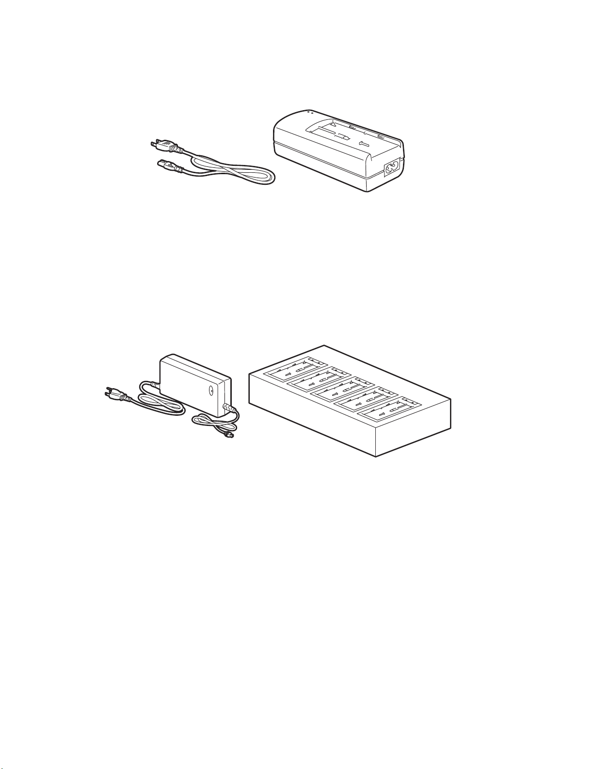
Figure 1-2, AC adapter
AC Adapter—allows the printer to be operated via an AC outlet, and to charge a battery pack
loaded inside the printer.
Warning: Use only the specified AC Adapter designed for your printer.
MB200i Operator Manual Page 1-9
Unit 1: Technical Data
Figure 1-3, Single slot battery charger
Single-slot Battery Charger—use this to charge a battery pack without using the printer
connected to an AC outlet.
Figure 1-4, Five-slot battery charger
Five-slot Battery Charger—use this to charge multiple spare battery packs at the same time.
Page 1-10 MB200i Operator Manual

Unit 1: Technical Data
PORTABILITY ENHANCEMENTS
Figure 1-5, Belt Holder
Belt Hook and Belt Holder—allows users to attach or detach the printer for the waist belt easily.
Figure 1-6, Attach printer to the belt holder
Installation: Pass your belt through the belt holder. Insert the belt hook into the belt holder until it
clicks into place. If the belt hook is not inserted properly, the printer may fall off.
Figure 1-7, Detach printer from the belt holder
Detachment: Pull the printer sideways and upwards to remove it from the belt hook.
MB200i Operator Manual Page 1-11
Unit 1: Technical Data
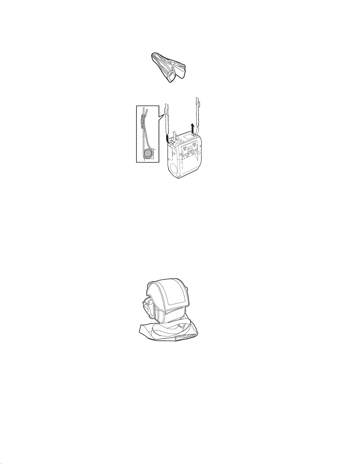
Figure 1-8, Preparing the Shoulder Strap
Shoulder Strap—allows users to hang the printer from the shoulder.
Installation: Thread the shoulder strap through the strap holes on the printer, from the outside to
the inside. Then thread the end of the shoulder strap through the buckle, and adjust the length.
Note: If the strap is not routed correctly, the printer may drop off.
Figure 1-9, Rain-resistant shoulder case
Rain-resistant Shoulder Case — allows users to protect the printer when carry it around during
wet weather.
Installation: Pinch the Rain-resistant case with the belt clip of the printer. If the Rain-resistant
case is not pinched with the belt clip correctly, the printer may fall off.
Note: Shoulder case can be used only for the printer without rubber boot installed.
Page 1-12 MB200i Operator Manual
Unit 1: Technical Data
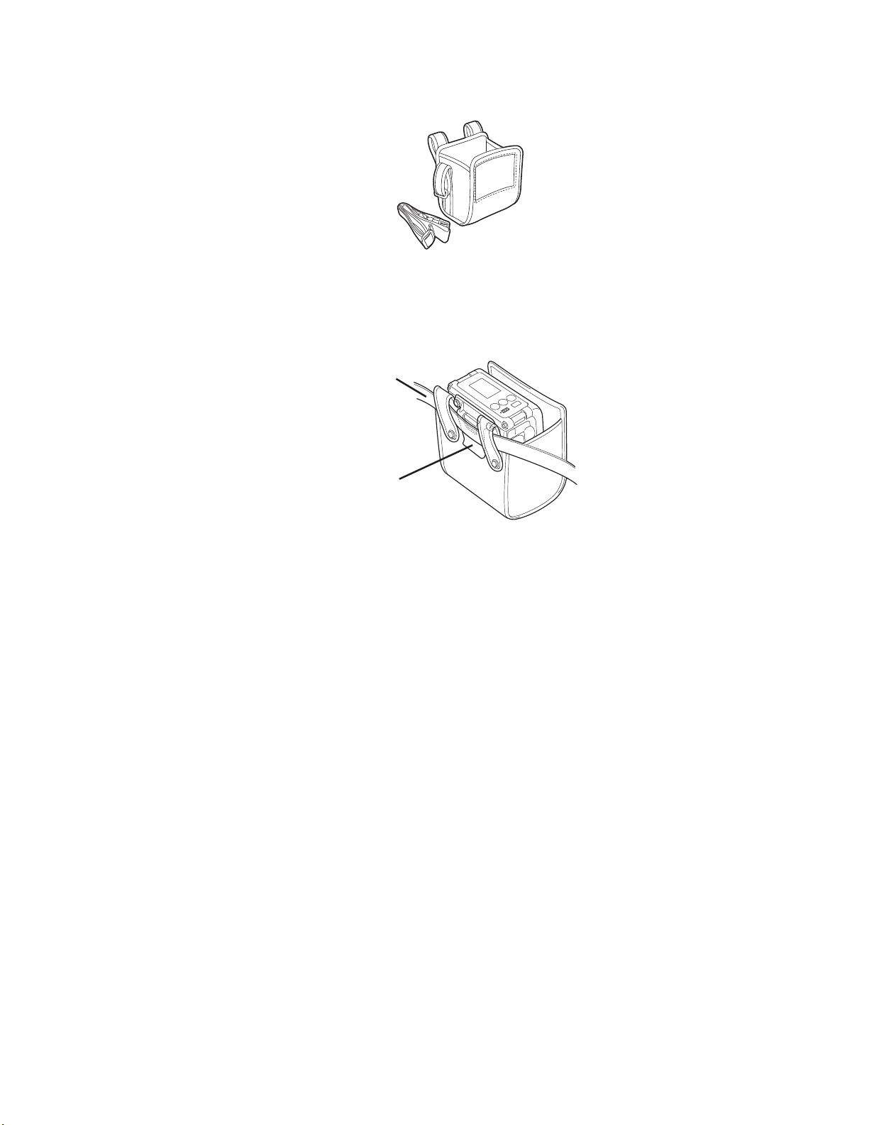
Waist belt
Belt Clip
Figure 1-10, Holster-waist case
Holster-waist case — a protective case that hangs from the waist for transporting the printer.
Figure 1-11, Pinch the Holster-waist case with the belt clip
Installation: Pinch the Holster-waist case with the belt clip of the printer. If the Holster-waist case
is not pinched by the belt clip correctly, the printer may fall off.
Note: The Holster-waist case can be used only for the printer without rubber boot installed.
CONNECTIVITY OPTIONS
RS-232C cable—allows connection of the printer to a PC or handy terminal.
ACTORY-INSTALLED OPTIONS
F
Wireless LAN Interface (with LCD)—allows printing via a WLAN network. The interface comes
with an LCD on the front panel to display the status of wireless communication.
Bluetooth Interface—allows printing via a Bluetooth connection.
For more details about the optional accessories, consult the Interfaces section of the Basic
Specifications table in this section of this manual, or consult your authorized SATO
representative.
MB200i Operator Manual Page 1-13

Unit 1: Technical Data
Page 1-14 MB200i Operator Manual

Unit 2: Overview
OVERVIEW
• Overview
MB200i Operator Manual Page 2-1

Unit 2: Overview
OVERVIEW
This manual is laid out consistent with the product discussed and provides all of the information
required for operation of the MB200i printer.
A comprehensive Table Of Contents provided at the front of this manual facilitates rapid
movement within. The contents identify the different Units, Chapters, and Sections. Each
references the page number of their commencement.
The pages of this manual have embedded headers and footers to assist the user in identifying
his or her exact position within the manual. The header provides the section number followed by
its name. The footer identifies the product on the left, and the page number to the right side of the
page.
Page enumeration is two-part with each separated by a hyphen. The first character set
references the Unit and the second identifies the page number. Page numbers begin with the
numeral (1) one at the commencement of a new unit and ascends sequentially.
This manual is intended to familiarize you with the basic features and operation of the MB200i
barcode printer in a short time.
PRODUCT FEATURES
Key features:
• High speed CPU and 103 mm/sec print speed (max)
• Long battery life
• Durable and rugged design
• Supports media up to 67 mm in width
• Built-in label dispenser
• Supports linerless media
• Available in IrDA, RS232C (standard), Bluetooth (optional), and IEEE802.11 b/g (optional)
interfaces
• Supports the MB200 compatible Programming Language or SATO Barcode Printer Language
Please read this manual carefully to make full use of this product. All information herein was
correct at the time of this document’s release. Revised versions of this document may be created
to match updates in firmware and procedures.
BLUETOOTH/WIRELESS COMMUNICATION
COMPLIANCE STATEMENT
This product has been certified for compliance with the relevant radio interference regulations of
your country or region. To ensure continued compliance, do not:
• Disassemble or modify this product
• Remove the certificate label (serial number seal) affixed to this product
Use of this product near microwave and/or other wireless LAN equipment, or where static
Page 2-2 MB200i Operator Manual
Unit 2: Overview
electricity or radio interference is present, may shorten the communication distance, or even
disable communication.
“Bluetooth” is a trademark of Bluetooth SIG, Inc., USA., and is used herein under license.
SAFETY PRECAUTIONS
This section outlines the safety precautions needed for safe operation of the printer. Make sure
to read the precautions carefully before using the printer.
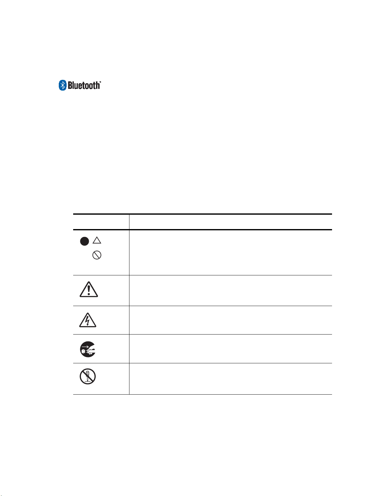
Symbols used in this manual:
The following symbols or markings are used in this manual and on the printer so that you can
properly use the printer, and to prevent any damage to property, harm or injury to yourself and
others.
Table 2-1, Symbols
SYMBOL MEANING
All safety symbols are enclosed by a circle or triangle. A black
circle is for an action you should do. A white circle with a bar
across it represents an action you should not do. A triangle
indicates that care is needed for that action, to avoid potential
hazards.
This symbol comes with the word Warning or Caution to alert
the user to be careful about an action to prevent (possible)
damage or injury.
This symbol alerts the user about the (possible) risk of electrical
shock if care is not observed when performing a certain action.
This symbol indicates that the user should remove the AC cord
by pulling the plug and not the cord.
This symbol indicates that the user should NOT attempt to dismantle or service the product.
MB200i Operator Manual Page 2-3

Unit 2: Overview
USAGE SAFETY
• Do not place the printer in a hot or cold place
The operation temperature range is -15°C to 50°C (for wireless LAN: 0 to 50°C) where humidity
is less than 80% and does not cause condensation. Do not place the printer in an area with high
humidity or at a temperature outside the specified range.
• Do not drop or apply undue shock to the printer
The printer is generally resistant to vibration possibly caused during normal transportation.
However, do not apply extreme vibration or shock by dropping the printer.
• Do not disassemble or modify the printer
The printer has high-precision components inside requiring fine adjustment.
• Connect the correct cables to the input terminals
Cables of the correct specifications are required for connection to the external equipment
through the external input terminals. Contact your nearest dealer or service center if necessary.
• Use the recommended accessories
Using optional equipment other than the specified equipment may cause a malfunction. Always
use the equipment specified in this guide.
• Use the correct media
Use the specified media. Otherwise, faulty printing or printer damage may occur.
SAGE WARNINGS
U
Table 2-2, Warnings
Do not place any container with water or chemicals, such as
flower vase or cup, as well as small metallic objects, near the
Liquids
printer. If any of these should drop into the printer, immediately
turn off the power and contact your nearest dealer or service
center. Continued use creates a danger of fire or electric shock.
Page 2-4 MB200i Operator Manual

Foreign Matter
Physical Shock
Abnormal Signs
Unit 2: Overview
Table 2-2, Warnings
Do not drop or insert metallic or flammable objects into the
openings on the printer (such as outlets for cables). If any of
these should fall into the printer,
immediately turn off the power and contact your nearest dealer
or service center. Continued use creates a danger of fire or
electric shock.
Should the printer ever be dropped or otherwise become
damaged, immediately turn off the power and contact your
nearest dealer or service center.
Continued use creates a danger of fire or electric shock.
Continued use of the printer while it is emitting smoke or strange
odors creates the danger of fire or electric shock. Immediately
turn off the power and contact your nearest dealer or service
center. Do not try to service the printer by yourself.
Never try to take the unit apart or modify it in any way. Doing so
creates the danger of fire or electric shock. Contact your nearest
dealer or service center for checking, adjustment, or repair.
Disassembly
Battery Pack
AC Adapter /
Battery Charger
(Option)
• Never try to take apart the battery pack or modify it in any
way such as with a solder iron.
• Never expose the battery to fire, or take any actions that may
lead to shorting.
• When charging the battery pack, make sure to use the
printer or the specified battery charger.
• Use only the specified voltage. Using a different voltage may
create the danger of fire or electric shock.
• Use only the specified AC adapter. Using a different adapter
unit may create the danger of fire or electric shock.
• Never use the battery charger with any other battery pack
except for the specified unit. Doing so can rupture the battery, cause leakage, or cause fire or an electric shock.
• Never cut, damage or modify the power cord. Also, never
place heavy objects on the power cord or heat or pull the
power cord. Doing so may damage the cord and create the
danger or fire or electric shocks.
• Should the power cord ever become seriously damaged
(internal wiring exposed or shorted), contact your nearest
dealer or service center for repair. Continued use of such a
cord creates the danger of fire or electric shock.
• Never modify, excessively bend, twist, or pull the power cord.
Doing so creates the danger of fire or electric shocks.
MB200i Operator Manual Page 2-5

Unit 2: Overview
USAGE PRECAUTIONS
Location
Power
Print Head
Table 2-3, Usage Precautions
Do not locate the printer in areas with high humidity or dew. If
dew forms inside the printer, immediately turn it off, and do not
use it until the dew has dried up. Otherwise, continued use
creates the danger of electric shocks or printer damage.
• Do not use wet hands to operate the power switch, replace
the battery pack or unplug the AC adapter or battery charger.
Doing so creates the danger of electric shocks.
• The AC adapter set provided for this printer is specific to this
printer. Do not use it for other electrical equipment.
• The print head gets very hot after printing. To avoid burns,
take care when replacing the label or cleaning the printer just
after printing.
• Touching the end of the print head with bare hands may
cause injury. Take care when replacing the label or cleaning
the printer.
• Do not try to replace the print head by yourself. Doing so creates the danger of injury, burns, or electric shocks.
Battery Pack
Storage
Maintenance
• When replacing the Battery Pack use only the specified
design.
• Make sure to install the pack in the correct orientation. Incorrectly replacing the battery creates the danger of injury or
damage to surrounding areas, if an explosion is caused.
• To dispose of a small rechargeable battery (Lithium ion battery), seal the metal contacts with tape, and ask our sales
representative or service center for the measures to be taken
to recycle the reusable materials. Do not place the battery
pack together with other batteries such as dry batteries.
If you have no plan to use the printer for a long time, remove the
battery pack from the printer and/or unplug the AC adapter from
the wall outlet before storing the printer (if you were using the AC
adapter as the power source).
For safe maintenance or cleaning of the printer, make sure to
remove the battery pack and the AC adapter from the printer.
Page 2-6 MB200i Operator Manual

Unit 3: Setup
SETUP
•Setup
MB200i Operator Manual Page 3-1
Unit 3: Setup
Quick Guide
Printer
Battery Pack
SETUP
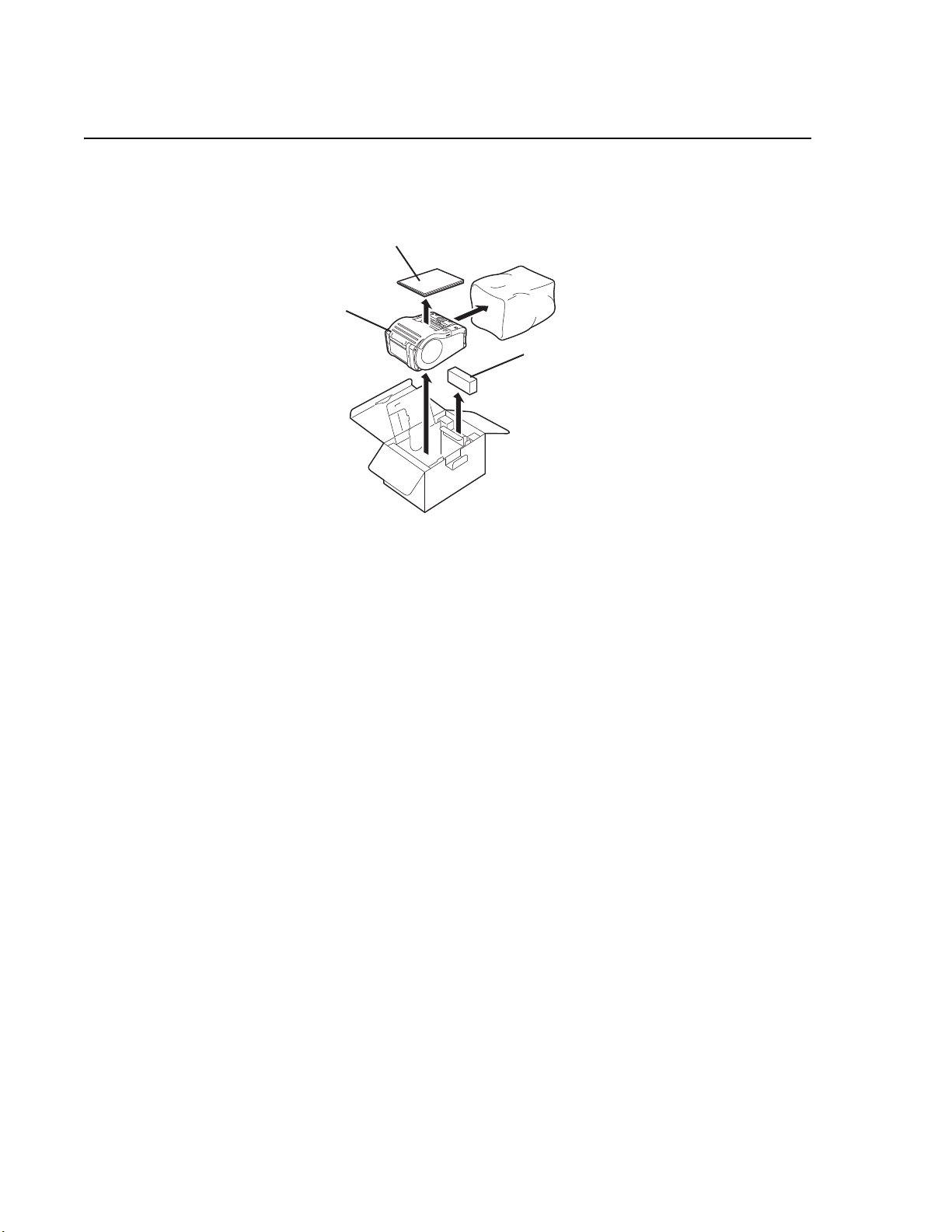
UNPACKING THE PRINTER
Figure 3-1, Unpacking the printer
OTES:
N
If any component shown here is missing, contact your nearest dealer or service center.
The printer is shipped with an integrated belt clip and a battery pack.
Page 3-2 MB200i Operator Manual
 Loading...