

Page 1

Barcode Printer MB200
MB200
Quick Guide
SATO#MB200#E#Hyo_1.p65 02.5.17, 2:50 PM1
Page 2

Warning!
This device complies with Part 15 of the FCC Rules.
Operation is subject to the following two conditions:
(1)This device may not cause harmful interference,and
(2)This device must accept any interference received,
including interference that may cause undesired
operation.
FCC Caution:
Changes or modifications not expressly approved by the
manufacturer for compliance could void the user's authority
to operate the equipment.
NOTE : This equipment has been tested and found to comply
with the limits for a Class B digital device, pursuant to
Part 15 of the FCC Rules.These limits are designed to provide
reasonable protection against harmful interference in
a residential installation.This equipment generates and can
radiate radio frequency energy and, if not installed and used
in accordance with instructions, may cause harmful interference
to radio communications. However, there is no guarantee that
interference will not occur in a particular installation.
If this equipment does cause harmful interference to radio or
television reception,
which can be determined by turning the equipment off and on,
the user is encouraged to try to correct the interference by one or
more of the following measures:
-Reorientate or relocate the receiving antenna.
-Increase the separation between the equipment and receiver.
-Connect the equipment into an outlet on a circuit
different from that to whcih the receiver is connected.
-Consult the dealer or an experienced radio/TV technician for help.
2
SATO#MB200##E.p65 02.5.17, 2:23 PM2
Page 3

Warning!
This manual show that both the specification of Bluetooth and wireless
LAN. Please reffer to the corresponding section which shows
specification of Bluetooth or wireless LAN.
Wireless LAN specification.
The available scientific evidence does not show that
any health problems are associated with using low power
wireless devices. There is no proof, however, that these
low power wireless devices are absolutely safe. Low
power Wireless devices emit low levels of radio frequency
energy (RF) in the microwave range while being used.
Whereas high levels of RF can produce health effects
(by heating tissue), exposure to low level RF that does not
produce heating effects causes no known adverse health
effects. Many studies of low level RF exposures have not
found any biological effects. Some studies have suggested
that same biological effects might occur, but such findings
have not been confirmed by additional research.
The (Wireless LAN Module (WM-B-AG-02)) has been tested
and found to comply with the Federal Communications
Commission (FCC) guidelines on radio fequency energy
(RF) exposures. The maximum SAR levels tested for the
(Wireless LAN Module (WM-B-AG-02))has been shown to be
(0.449)W/kg at (Body). This device should not be
co-located or operated with any other antenna transmitter.
3
SATO#MB200##E.p65 02.5.17, 2:23 PM3
Page 4
Features of the MB200
With its compact and lightweight body combined with high
performance, this printer prints crisp barcodes on various
types of thermal paper.
ÐExcellent Printing Performance
Not only does this printer print barcodes clearly, but it can
also enlarge and print various types of fonts and Kanji
characters in a free layout.
ÐDurable and Easy to Use
This printer is also superb in durability, as it has been
designed specially for printing barcodes. Also,
special consideration has been taken so that the printer can
be easily cleaned everyday.
ÐDispenser Function
As a portable printer, this printer can easily print and
dispense labels to enable the application of labels on site.
Table of Contents
1. Safety Precautions ......................................5
Markings and Symbols .............................5
Precautions in Use ................................. 13
2. Unpacking..................................................14
3. Parts Name................................................15
Name and Function of Operating Parts .. 17
4. Before Starting...........................................18
Preparation/Operation
Charging the Battery Pack...................... 18
Installing and removing the Battery Pack ..
Setting Labels ......................................... 22
20
4
SATO#MB200##E.p65 02.5.17, 2:23 PM4
Page 5

1. Safety Precautions
In this section, safety precautions about printer operation are
explained to ensure proper care and usage. Make sure to
read these carefully before using your printer.
The specification of wireless LAN for MB400 conforms to R&TTE.
Markings and Symbols
The following symbols or markings are used in this quick
guide and on the printer so that you can properly use the
printer, and to prevent any damage to property, harm or
injury to yourself and others. Make sure to read their
explanations carefully to familiarize yourself with their
meanings.
This symbol indicates information that, if
Warning
Caution
ignored or applied incorrectly, creates the
danger of death or serious personal
injury.
This symbol indicates information that, if
ignored or applied incorrectly, creates the
possibility of personal injury or property
damage.
1
Safety Precautions
5
SATO#MB200##E.p65 02.5.17, 2:23 PM5
Page 6

Symbol example
The triangle (
1
Safety Precautions
take absolute care with. The cautions are indicated
concretely within the symbol. The symbol on the
left indicates risk of electric shock.
A diagonal line within a circle (
something you should not do. The symbol on the left
indicates you should not try to take the unit apart.
) indicates something you should
) indicates
A black circle (
do. The symbol on the left indicates you should
unplug the unit from the wall outlet.
6
SATO#MB200##E.p65 02.5.17, 2:23 PM6
) indicates something you need to
Page 7

Warning!
Liquids
Do not place any containers with water or chemicals,
such as flower vases or cups, as well as small
metallic objects, near the printer. If any of these
should fall into the printer, immediately turn off the
power and contact your nearest dealer or service
center. Continued use creates the danger of fire or
electrical shock.
Foreign Matter
Do not drop or insert metallic or flammable objects
into the openings on the printer (such as outlets for
cables). If any of these should fall into the printer,
immediately turn off the power and contact your
nearest dealer or service center. Continued use
creates the danger of fire or electrical shock.
Dropping and Damage
Should the printer ever fall or otherwise become
damaged, immediately turn off the power and contact
your nearest dealer or service center. Continued use
creates the danger of fire or electrical shock.
1
Safety Precautions
7
SATO#MB200##E.p65 02.5.17, 2:23 PM7
Page 8

1
Abnormal Conditions
Safety Precautions
Continued use of the printer while it is emitting smoke
or strange odors, creates the danger of fire or electrical
shock. Immediately turn off the power and contact
your nearest dealer or service center for repairs. Do
not try to service the printer by yourself.
Disassembly
Never try to take the unit apart or modify it in any
way. Doing so creates the danger of fire or electrical
shock. Contact your nearest dealer or service center
for repairs.
Battery Pack
• Never try to take apart the battery pack or modify it
in any way such as with a solder iron.
• Never expose the battery to direct flame, throw it
into fire, or take any actions that may lead to
shorting.
• When charging the battery pack, make sure to use
the specified battery charger.
8
Warning!
SATO#MB200##E.p65 02.5.17, 2:23 PM8
Page 9
Warning!
AC Adapter / Battery Charger (Optional)
• Use only the specified voltage. Using a different
voltage may create the danger of fire or electrical
shock.
• Never use the battery charger with any other
battery pack except for the specified one. Doing so
can rupture the battery, cause leakage, fire or
electrical shock.
• Never cut, damage or modify the power cord. Also,
never place heavy objects on, set fire to or pull the
power cord, as it can damage the cord and create
the danger of fire or electrical shock.
• Should the power cord ever become seriously
damaged (internal wiring exposed or shorted),
contact your nearest dealer or service center.
Continued use of such a cord creates the danger of
fire or electrical shock.
• Never modify, excessively bend, twist, or pull the
power cord. Doing so creates the danger of fire or
electrical shock.
1
Safety Precautions
9
SATO#MB200##E.p65 02.5.17, 2:23 PM9
Page 10
1
Location
Safety Precautions
Do not locate the printer in areas subjected to high
humidity or dew. If dew forms inside the printer,
immediately turn off the power and do not use it until
it has dried up. Continued use creates the danger of
electrical shock.
Power
Do not use wet hands to operate the power switch,
replace the battery pack or unplug the AC adapter or
battery charger. Doing so creates the danger of
electrical shock.
This product is intended to be supplied by a power
supply(AC adapter) identified as both of the following:
A. Listed Power Unit marked "class2" or I.T.E Power
Supply marked "LPS" or UL1950 Power Supply marked
"LPS" and rated 7.2V to 9.0Vdc, 3000mA; and
B.CB certified AC adapter, Model SA130A-0930U-S
rated 8.4Vdc or 9.0Vdc, or an alternate CB certified AC
Adapter which will be added in the CB certification of
the product.
10
Caution!
SATO#MB200##E.p65 02.5.17, 2:23 PM10
Page 11
Caution!
Thermal Head and Stepping Motor
• The thermal head gets very hot after printing. Take
care when replacing labels after printed and when
cleaning to avoid burn.
• Touching the edge of the thermal head with bare
hands may cause injury. Take care when replacing
labels or cleaning to avoid injury.
• Do not try to replace the thermal head by yourself.
Doing so creates the danger of injury, burns or
electric shock.
Easy Cutter
This part contains a blade. Take care to avoid cutting
your hands.
1
Safety Precautions
11
SATO#MB200##E.p65 02.5.17, 2:23 PM11
Page 12

1
Replacing the Battery Pack
Safety Precautions
• Use only the specified battery pack.
• When replacing the battery pack, make sure to
install the pack with the poles (+) and (–) facing the
correct direction. Incorrectly replacing the battery
can rupture the battery and create the danger of
injury or damage to surrounding areas due to
leakage.
• When disposing of old battery packs, make sure to
contact your nearest dealer or service center.
Not using the printer for a long time
• Remove the battery pack from the printer and
unplug the AC adapter from the wall outlet if you do
not plan to use the printer for a long time.
Maintenance and Cleaning
• For safety during maintenance and cleaning, make
sure to remove the battery pack and the AC
adapter from the printer.
12
Caution!
SATO#MB200##E.p65 02.5.17, 2:23 PM12
Page 13

Precautions in Use
Do not place the printer in hot or cold places.
The operation temperature range is within 5 'C to 40 'C. Do not
place it in areas with high humidity or temperature out of the
operation range.
Wireless LAN & Buetooth specification.
IC(Industry Canada)Caution:
"The installer of this radio equipment must ensure that the antenna
is located or pointed such that it does not emit RF field in excess of
Health Canada limits for the general population;consult Safety Code
6,obtainable from Health Canada's website www.hc-sc.gc.ca/rpb"
CE Caution:
Hereby, SATO CORPORATION declares that this WM-B-AG-02 is in
compliance with the essential requirements and other relevant
provisions of Directive 1999/5/EC.
1
Safety Precautions
Bluetooth Specification
Wireless LAN specification.
If you want to get a copy of the original Declaration of Conformity of
our products which relates the R&TTE,please contact to web address:
www.barcodesato.com
SATO#MB200##E.p65 02.5.17, 2:23 PM13
0560
13
Page 14

2. Unpacking
After opening the box, make sure that all the printer’s
2
accessories are included. If there are any accessories
Unpacking
missing, contact your nearest dealer or service center.
Quick Guide
Printer
Battery pack
14
SATO#MB200##E.p65 02.5.17, 2:23 PM14
Page 15

3. Parts Name
Open cover
Dispenser unit
Dispense /
Continuous
switch lever
Power switch
Protection case
Easy cutter
Interface connector (RS-232C)
Label ejection
Cover Open/
Close lever
Interface cover
Belt hook
DC input jack cap
DC input jack
3
Parts Name
15
SATO#MB200##E.p65 02.5.17, 2:23 PM15
Page 16
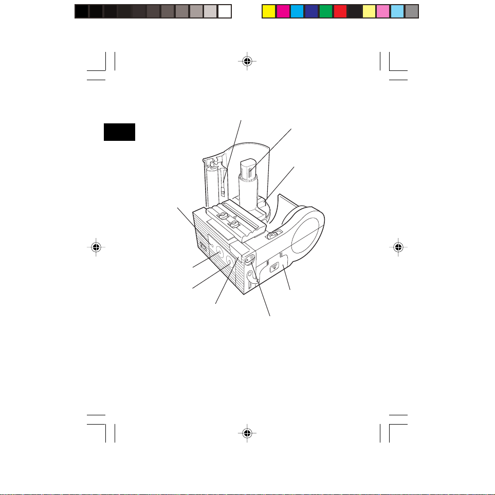
3
Parts Name
Status
indicator
(LED)
Print key
Label guide (Left)
Label width scale
Label guide (Right)
Feed key
IrDA filter
16
SATO#MB200##E.p65 02.5.17, 2:23 PM16
Battery cover
IrDA angle lever
Page 17

Name and Function of Operating Parts
Interface connector (RS232C):
Used for connecting to a
computer.
Interface cover:
Cover for the interface
connector.
Open cover:
Opened for setting labels.
Cover Open/Close lever:
Used for opening and closing
the cover.
Easy cutter:
Used for cutting printed labels.
IrDA adjustment lever:
Used for changing the angle of
the IrDA receiving element.
IrDA filter:
The IrDA receiving element is
located inside.
Dispenser unit:
Moved when the Dispense
mode is selected.
Power switch:
Used for turning the power on
and off.
Battery cover:
The battery pack is inserted
here.
Belt hook:
Used when hanging the printer
on the belt.
* Do not hang the printer on to
anything else but a belt.
Label guide:
Adjusted to the label size being
used.
Label ejection:
The printed label comes out
from there.
Label width scale:
Scale for measuring the width
of the label being used.
DC input jack:
Used for connecting the AC
adapter.
DC input jack cap:
Cap for covering the DC input
jack.
Feed key:
For feeding labels
Print key:
For setting the printer to online or
offline.
Status indicator (LED)
For displaying the status of the
printer.
3
Parts Name
17
SATO#MB200##E.p65 02.5.17, 2:23 PM17
Page 18

4. Before Starting
4
Charging the Battery Pack
Before Starting
Place the battery pack on the battery charger (optional) to
charge it.
1 Plug one end of the power cord
into the battery charger and the
other end into the wall outlet.
2 Place the battery pack on the
battery charger and slide it in the
direction of the arrow.
When the battery pack starts
charging, the charger indicator will
light up in orange. When the battery
pack is fully charged, the charger
indicator will turn off. (Fully
charged).
3 Remove the battery pack from
the charger after it has finished
charging.
Slide the battery pack from the
charger in the opposite direction to
when placed on the charger.
18
C
H
A
R
G
E
SATO#MB200##E.p65 02.5.17, 2:23 PM18
Page 19
Notice
• If the indicator on the charger does not light up, make sure
that the battery pack is firmly attached to the charger. The
battery may not charge, if not firmly attached.
• When an already charged battery pack has been attached
on the charger, the indicator on the charger will turn on
once and then off.
• If charging a battery pack that has not been used for a
long period, the indicator on the charger may flash for a
while. This does not indicate an error, and you can
continue charging as it is.
• The battery pack can be charged up to 300 times (during
use in regular temperatures). If the battery pack is fully
charged but soon runs out, replace the battery pack with a
new one.
Charging Time
The duration of charging the battery pack from empty until
fully charged is about 2.5 hours.
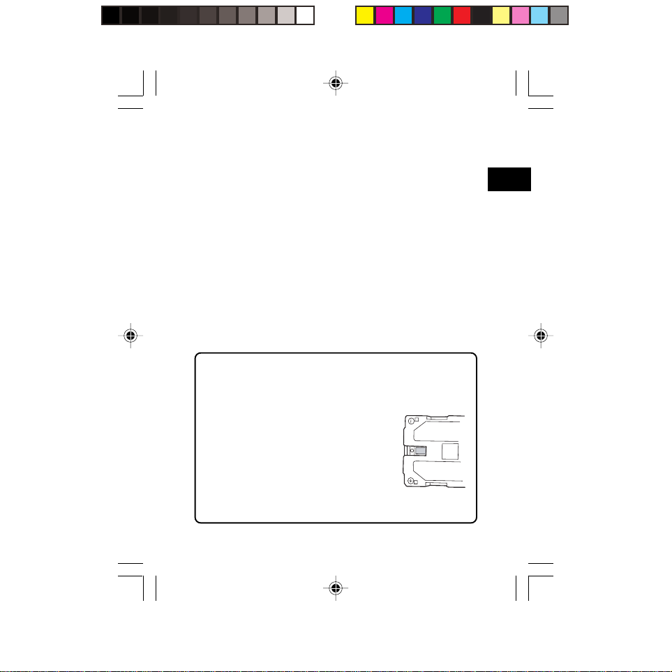
Battery pack charge confirmation mark
When the battery pack is removed from
the printer, the charge confirmation mark
on the back of the battery pack is blank.
When attaching the battery pack on the
charger once and then removing it, a
green black box (■) will appear on the
back of the pack.
By looking at the confirmation mark, you can check if the
battery is charged or not.
4
Before Starting
19
SATO#MB200##E.p65 02.5.17, 2:23 PM19
Page 20

Installing and removing the Battery Pack
* Remove the Protection case.
4
1 Place your finger on the battery
Before Starting
cover ribbed area, and slide it as
far as it will move in the direction
of the arrow.
2 After releasing the battery cover
lock, open the battery cover in
the direction of the arrow.
3 Insert the battery pack.
After that, take the above
procedure in reverse order
to close the battery cover.
20
SATO#MB200##E.p65 02.5.17, 2:23 PM20
Page 21
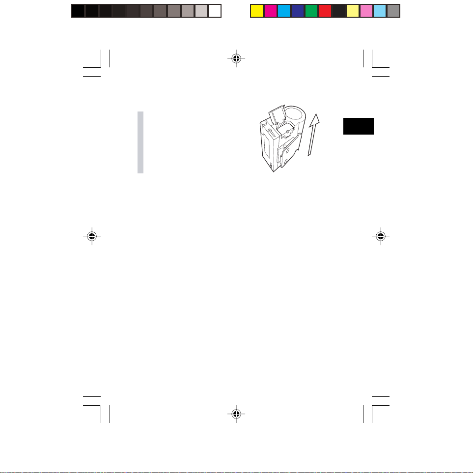
4 When removing the battery, place
your finger into the notch on the
battery and pull the battery out.
4
* Make sure to turn the power off when removing or
replacing the battery.
When the power is turned off, the status indicator will light
up in green. Do not remove the battery while the indicator
lights up. After making sure that the status indicator is off,
you may then remove the battery.
* If, after turning the power off, you remove the battery pack
while the status indicator is lit in green, the information
stored in the printer may not be updated.
SATO#MB200##E.p65 02.5.17, 2:23 PM21
Before Starting
21
Page 22

Setting Labels
The method of setting the labels may vary depending on the
4
print mode.
Before Starting
Continuous mode
Labels
* Remove the Protection case.
1 Place your fingers on the open
cover ribbed area, and slide the
cover Open/Close lever in the
direction of the arrow.
* Slide the Open/Close lever until
the L mark on the lever is covered.
2 When the open cover pops open,
fully open the cover in the
direction of the arrow.
22
SATO#MB200##E.p65 02.5.17, 2:23 PM22
Open cover
Cover Open/
Close lever
Page 23

3
Place the label roll on the spindle on
the open cover side.
*When inserting the label roll, make
sure to press it down to prevent the
labels from raveling out.
* When removing remaining labels,
insert your finger in the label core
and remove the label with the core to
prevent the labels from raveling out.
4 After peeling the leading tape on
the roll, take the leading edge of
the first label of the roll and pull it
out from the label ejection via the
platen roller. Then, adjust the
label guide (left) to the label size,
and pass the label underneath
the label guides.
5 Place your fingers on the open
cover ribbed area, and close the
open cover.
Label set position
This completes the setting of labels when using the
Continuous mode.
Label guide
(Left)
4
Before Starting
23
SATO#MB200##E.p65 02.5.17, 2:23 PM23
Page 24

SATO#MB200#E#Hyo_4.p65 02.5.17, 2:51 PM1
Q 0 0 3 1 9 0 1 0
 Loading...