

Page 1
®
CL Series
Thermal Transfer Printers
Operator and Technical
Reference Manual for
CL408, CL412, CL608VA &
CL612VA
PN9001035Rev.E
Page 2

SATO America, Inc.
10350-A Nations Ford Rd.
Charlotte, NC 28273
MainPhone:(704) 644-1650
Technical SupportHotline:(704) 644-1660
Fax:(704) 644-1661
www.satoamerica.com
© Copyright 1994, 1995, 1996, 1997, 1999
SATO America, Inc.
Warning: This equipment complies with the requirements in Part 15 of
FCC rules for a Class A computing device. Operation of this equipment in a
residential area may cause unacceptable interference to radio and TV
reception requiring the operator to take whatever steps are necessary to
correct the interference.
All rights reserved. No part of this document may be reproduced or issued
to third parties in any form whatsoever without the express permission of
SATO America, Inc. The materials in this document is provided for general
information and is subject to change without notice. SATO America, Inc.
assumes no responibilities for any errors that may appear.
SATOCLSeriesPrinters PN9001035RevE
Page 3

PREFACE
CL SERIES PRINTER OPERATOR’S MANUAL
The CL Series Printer Operator’s Manual contains basic information about the printer
such as setup, installation, cleaning and maintenance. It also contains complete
instructions on how to use the operator panel to configure the printer. The following
is a brief description of each section in this manual.
SECTION 1. PRINTER OVERVIEW
This section contains a discussion of the printer specifications and optional
features.
SECTION 2. INSTALLATION AND CONFIGURATION
This section contains instructions on how to unpack and set up the printer,
load the labels and ribbon, and how to use the operator panel to configure the
printer.
SECTION 3. CLEANING AND MAINTENANCE
This section contains instructions on how to clean and maintain the printer.
SECTION 4. PROGRAMMING
This section introduces the SATO printer programming language. It contains
the commands that are used with the printer to produce labels with bar codes,
alphanumeric data and graphics.
SECTION 5. INTERFACE SPECIFICATIONS
This section contains the printer’s interface specifications, which include
detailed information on how to properly interface your printer to the host
system.
SECTION 6. TROUBLESHOOTING
This section contains troubleshooting procedures to follow in the event you
have printer problems.
SATOCLSeriesPrinters9001035Rev.E Page-i
Page 4

Preface
APPENDICES
APPENDIX A: Command Code Quick Reference
APPENDIX B: Bar Code Specifications
APPENDIX C: Custom Characters and Graphics
APPENDIX D: Optional Features
APPENDIX E: Custom Protocol Command Codes
APPEDDIX F: Label Wizard Support
Page-ii9001035Rev.E SATOCLSeriesPrinters
Page 5

TABLE OF CONTENTS
SECTION 1. PRINTER OVERVIEW
Introduction . . . . . . . . . . . . . . . . . . . . . . . . . . . . . 1-1
General Printer Specifications . . . . . . . . . . . . . . . . . . . . 1-2
Character Fonts . . . . . . . . . . . . . . . . . . . . . . . . . . . . 1-4
Bar Codes . . . . . . . . . . . . . . . . . . . . . . . . . . . . . . . 1-5
Physical . . . . . . . . . . . . . . . . . . . . . . . . . . . . . . . . 1-6
Optional Accessories . . . . . . . . . . . . . . . . . . . . . . . . . 1-7
SECTION 2. INSTALLATION AND CONFIGURATION
Introduction . . . . . . . . . . . . . . . . . . . . . . . . . . . . . 2-1
Unpacking and Parts Identification . . . . . . . . . . . . . . . . . . 2-2
Setting Up the Printer . . . . . . . . . . . . . . . . . . . . . . . . 2-3
Loading Labels, Tags and Ribbon in the CL608 and CL612 . . . . . . 2-4
Loading Labels, Tags and Ribbon in the CL408 and CL412 . . . . . . 2-8
Operator Panel . . . . . . . . . . . . . . . . . . . . . . . . . . . . 2-12
CL608 and CL612 . . . . . . . . . . . . . . . . . . . . . . . . . 2-12
CL408 and CL412 . . . . . . . . . . . . . . . . . . . . . . . . . 2-14
Rear Panel . . . . . . . . . . . . . . . . . . . . . . . . . . . . . . 2-16
CL608 and CL612 . . . . . . . . . . . . . . . . . . . . . . . . . 2-16
CL408 and CL412 . . . . . . . . . . . . . . . . . . . . . . . . . 2-17
Switches and Sensors . . . . . . . . . . . . . . . . . . . . . . . . . 2-18
CL608 and CL612 . . . . . . . . . . . . . . . . . . . . . . . . . 2-18
CL408 and CL412 . . . . . . . . . . . . . . . . . . . . . . . . . 2-19
Printer DIP Switch Configuration, All Models . . . . . . . . . . . . . 2-20
Printer Adjustments, All Models . . . . . . . . . . . . . . . . . . . 2-24
Potentiometer Adjustments, All Models . . . . . . . . . . . . . . . . 2-39
Printing Hex Dump Diagnostic Labels . . . . . . . . . . . . . . . . 2-41
Preface
SECTION 3. CLEANING AND MAINTENANCE
Introduction . . . . . . . . . . . . . . . . . . . . . . . . . . . . . 3-1
Procedures, CL608 and CL612 . . . . . . . . . . . . . . . . . . . . 3-1
Adjusting the Print Quality . . . . . . . . . . . . . . . . . . . . 3-1
Darkness . . . . . . . . . . . . . . . . . . . . . . . . . . . 3-1
Print Speed . . . . . . . . . . . . . . . . . . . . . . . . . . 3-2
Cleaning the Print Head, Platen and Rollers . . . . . . . . . . . 3-2
Replacing the Print Head . . . . . . . . . . . . . . . . . . . . . 3-4
Cleaning the Sensors . . . . . . . . . . . . . . . . . . . . . . . 3-5
Replacing the Fuse . . . . . . . . . . . . . . . . . . . . . . . . 3-6
SATOCLSeriesPrinters9001035Rev.E Page-iii
Page 6

Preface
Procedures, CL408 and CL412 . . . . . . . . . . . . . . . . . . . . 3-7
Adjusting the Print Quality . . . . . . . . . . . . . . . . . . . . 3-7
Darkness . . . . . . . . . . . . . . . . . . . . . . . . . . . 3-7
Speed . . . . . . . . . . . . . . . . . . . . . . . . . . . . . 3-7
Cleaning the Print Head and Platen . . . . . . . . . . . . . . . 3-8
Replacing the Print Head . . . . . . . . . . . . . . . . . . . . . 3-9
Cleaning the Sensors . . . . . . . . . . . . . . . . . . . . . . . 3-10
Replacing the Fuse . . . . . . . . . . . . . . . . . . . . . . . . 3-11
SECTION 4. PROGRAMMING
Introduction . . . . . . . . . . . . . . . . . . . . . . . . . . . . . 4-1
The SATO CL Programming Language . . . . . . . . . . . . . . . . 4-1
Selecting Protocol Control Codes . . . . . . . . . . . . . . . . . . . 4-2
Using Basic . . . . . . . . . . . . . . . . . . . . . . . . . . . . . . 4-2
The Print Area . . . . . . . . . . . . . . . . . . . . . . . . . . . . 4-4
Rotated Fields . . . . . . . . . . . . . . . . . . . . . . . . . . . . 4-8
Command Default Settings . . . . . . . . . . . . . . . . . . . . . . 4-9
Command Codes . . . . . . . . . . . . . . . . . . . . . . . . . . . 4-10
Bar Codes . . . . . . . . . . . . . . . . . . . . . . . . . . . . . 4-11
Bar Codes, Expansion . . . . . . . . . . . . . . . . . . . . . . . 4-16
Bar Codes, Variable Ratio . . . . . . . . . . . . . . . . . . . . . 4-17
Base Reference Point . . . . . . . . . . . . . . . . . . . . . . . 4-19
Characters, Custom Designed . . . . . . . . . . . . . . . . . . . 4-21
Character Expansion . . . . . . . . . . . . . . . . . . . . . . . 4-23
Character, Fixed Spacing . . . . . . . . . . . . . . . . . . . . . 4-25
Character Pitch . . . . . . . . . . . . . . . . . . . . . . . . . . 4-26
Character, Proportional Spacing . . . . . . . . . . . . . . . . . 4-28
Clear Print Job(s) and Memory . . . . . . . . . . . . . . . . . . 4-29
Continuous Forms Printing . . . . . . . . . . . . . . . . . . . . 4-30
Copy Image Area . . . . . . . . . . . . . . . . . . . . . . . . . 4-31
Cutter Command . . . . . . . . . . . . . . . . . . . . . . . . . 4-33
Fonts, U, S, M, OA, OB, XU, XS and XM . . . . . . . . . . . . . 4-34
Fonts, Vector . . . . . . . . . . . . . . . . . . . . . . . . . . . 4-36
Fonts, WB,WL, XB and XL . . . . . . . . . . . . . . . . . . . . 4-38
Form Feed . . . . . . . . . . . . . . . . . . . . . . . . . . . . 4-40
Form Overlay Recall . . . . . . . . . . . . . . . . . . . . . . . 4-41
Form Overlay Store . . . . . . . . . . . . . . . . . . . . . . . . 4-42
Graphics, Custom . . . . . . . . . . . . . . . . . . . . . . . . . 4-43
Graphics, PCX . . . . . . . . . . . . . . . . . . . . . . . . . . 4-45
Job ID Store . . . . . . . . . . . . . . . . . . . . . . . . . . . 4-46
Journal Print . . . . . . . . . . . . . . . . . . . . . . . . . . . 4-47
Lines and Boxes . . . . . . . . . . . . . . . . . . . . . . . . . . 4-48
Line Feed . . . . . . . . . . . . . . . . . . . . . . . . . . . . . 4-50
Mirror Image . . . . . . . . . . . . . . . . . . . . . . . . . . . 4-52
Off-Line . . . . . . . . . . . . . . . . . . . . . . . . . . . . . . 4-54
Postnet . . . . . . . . . . . . . . . . . . . . . . . . . . . . . . 4-55
Print Darkness . . . . . . . . . . . . . . . . . . . . . . . . . . 4-56
Print Length, Expanded . . . . . . . . . . . . . . . . . . . . . . 4-57
Print Position . . . . . . . . . . . . . . . . . . . . . . . . . . . 4-59
Page-iv9001035Rev.E SATOCLSeriesPrinters
Page 7

Preface
Print Quantity . . . . . . . . . . . . . . . . . . . . . . . . . . . 4-61
Print Speed . . . . . . . . . . . . . . . . . . . . . . . . . . . . 4-62
Repeat Label . . . . . . . . . . . . . . . . . . . . . . . . . . . 4-63
Replace Data (Partial Edit) . . . . . . . . . . . . . . . . . . . . 4-64
Reverse Image . . . . . . . . . . . . . . . . . . . . . . . . . . 4-66
Rotate, Fixed Base Reference Point . . . . . . . . . . . . . . . . 4-68
Rotate, Moving Base Reference Point . . . . . . . . . . . . . . . 4-70
Sequential Numbering . . . . . . . . . . . . . . . . . . . . . . 4-72
Start/Stop Label . . . . . . . . . . . . . . . . . . . . . . . . . 4-74
Calendar Option Commands . . . . . . . . . . . . . . . . . . . 4-75
Calendar Increment . . . . . . . . . . . . . . . . . . . . . . 4-76
Calendar Print . . . . . . . . . . . . . . . . . . . . . . . . 4-78
Calendar Set . . . . . . . . . . . . . . . . . . . . . . . . . 4-80
Memory Card Option Commands . . . . . . . . . . . . . . . . . 4-81
Clear Card Memory . . . . . . . . . . . . . . . . . . . . . . 4-82
Expand Memory Area . . . . . . . . . . . . . . . . . . . . . 4-83
Fonts, TrueType Recall . . . . . . . . . . . . . . . . . . . . 4-85
Fonts, TrueType Store . . . . . . . . . . . . . . . . . . . . 4-86
Format/Field Recall . . . . . . . . . . . . . . . . . . . . . . 4-87
Format/Field Store . . . . . . . . . . . . . . . . . . . . . . 4-88
Graphics, Custom Recall . . . . . . . . . . . . . . . . . . . 4-89
Graphics, Custom Store . . . . . . . . . . . . . . . . . . . . 4-90
Graphics, PCX Recall . . . . . . . . . . . . . . . . . . . . . 4-92
Graphics, PCX Store . . . . . . . . . . . . . . . . . . . . . . 4-93
Initialize . . . . . . . . . . . . . . . . . . . . . . . . . . . 4-94
Slot Select . . . . . . . . . . . . . . . . . . . . . . . . . . 4-95
Status . . . . . . . . . . . . . . . . . . . . . . . . . . . . . 4-96
Custom Protocol Codes Download . . . . . . . . . . . . . . . . 4-97
Two-Dimensional Symbols . . . . . . . . . . . . . . . . . . . . 4-99
Data Matrix, Data Format . . . . . . . . . . . . . . . . . . . 4-100
Data Matrix, Data Print . . . . . . . . . . . . . . . . . . . . 4-102
Dat Matrix Sequential Numbering . . . . . . . . . . . . . . 4-103
Maxicode . . . . . . . . . . . . . . . . . . . . . . . . . . . 4-105
PDF417 . . . . . . . . . . . . . . . . . . . . . . . . . . . . 4-107
SECTION 5. INTERFACE SPECIFICATIONS
Introduction . . . . . . . . . . . . . . . . . . . . . . . . . . . . . 5-1
Interface Types . . . . . . . . . . . . . . . . . . . . . . . . . . . . 5-1
The Receive Buffer . . . . . . . . . . . . . . . . . . . . . . . . . . 5-1
RS232C Serial Interface . . . . . . . . . . . . . . . . . . . . . . . 5-3
General Specifications . . . . . . . . . . . . . . . . . . . . . . 5-3
Electrical Specifications . . . . . . . . . . . . . . . . . . . . . . 5-3
Pin Assignments . . . . . . . . . . . . . . . . . . . . . . . . . 5-4
Ready/Busy Flow Control . . . . . . . . . . . . . . . . . . . . . 5-4
X-On/X-Off Flow Control . . . . . . . . . . . . . . . . . . . . . 5-5
Bi-Directional Communications . . . . . . . . . . . . . . . . . . 5-6
Centronics Parallel Interface . . . . . . . . . . . . . . . . . . . . . 5-9
Electrical Specifications . . . . . . . . . . . . . . . . . . . . . . 5-9
Accessory (EXT) Connector . . . . . . . . . . . . . . . . . . . . . . 5-10
Pin Assignments . . . . . . . . . . . . . . . . . . . . . . . . . 5-10
External Output Signals . . . . . . . . . . . . . . . . . . . . . . 5-11
SATOCLSeriesPrinters9001035Rev.E Page-v
Page 8

Preface
SECTION 6. TROUBLESHOOTING
Initial Checklist . . . . . . . . . . . . . . . . . . . . . . . . . . . . 6-1
Using the Centronics (Parallel) Interface . . . . . . . . . . . . . . . 6-1
Using the RS232C (Serial) Interface . . . . . . . . . . . . . . . . . 6-3
Error Signals . . . . . . . . . . . . . . . . . . . . . . . . . . . . . 6-4
CL608 and CL612 . . . . . . . . . . . . . . . . . . . . . . . . 6-4
CL408 and CL412 . . . . . . . . . . . . . . . . . . . . . . . . 6-5
APPENDICES
APPENDIX A: Command Code Quick Reference
APPENDIX B: Bar Code Specifications
Bar Code Symbologies . . . . . . . . . . . . . . . . . . . . . . B-1
Codabar . . . . . . . . . . . . . . . . . . . . . . . . . . . . B-2
Code 39 . . . . . . . . . . . . . . . . . . . . . . . . . . . . B-3
Interleaved Two of Five (I 2/5) . . . . . . . . . . . . . . . . B-4
UPC-A/EAN-13 . . . . . . . . . . . . . . . . . . . . . . . . B-5
EAN-8 . . . . . . . . . . . . . . . . . . . . . . . . . . . . . B-6
Industrial Two of Five . . . . . . . . . . . . . . . . . . . . B-8
Matrix Two of Five . . . . . . . . . . . . . . . . . . . . . . B-9
Code 128 . . . . . . . . . . . . . . . . . . . . . . . . . . . B-10
MSI . . . . . . . . . . . . . . . . . . . . . . . . . . . . . . B-11
Code 93 . . . . . . . . . . . . . . . . . . . . . . . . . . . . B-12
UPC-E . . . . . . . . . . . . . . . . . . . . . . . . . . . . . B-13
Bookland (UPC/EAN Supplements) . . . . . . . . . . . . . B-14
UCC-128 . . . . . . . . . . . . . . . . . . . . . . . . . . . B-15
Postnet . . . . . . . . . . . . . . . . . . . . . . . . . . . . B-17
Data Matrix . . . . . . . . . . . . . . . . . . . . . . . . . . B-18
Maxicode . . . . . . . . . . . . . . . . . . . . . . . . . . . B-20
PDF417 . . . . . . . . . . . . . . . . . . . . . . . . . . . . B-21
Code 128 Character Table . . . . . . . . . . . . . . . . . . B-22
APPENDIX C: Custom Characters and Graphics
Custom Designed Characters Example . . . . . . . . . . . . . . C-1
Custom Graphics Example . . . . . . . . . . . . . . . . . . . . C-4
PCX Graphics Example . . . . . . . . . . . . . . . . . . . . . . C-8
Page-vi9001035Rev.E SATOCLSeriesPrinters
Page 9

APPENDIX D: Optional Accessories
Label Rewinder, All Models . . . . . . . . . . . . . . . . . . . . D-1
Label Cutter, All Models . . . . . . . . . . . . . . . . . . . . . D-2
Label Dispense Option . . . . . . . . . . . . . . . . . . . . . . D-3
CL608 and CL612 . . . . . . . . . . . . . . . . . . . . . . . D-3
CL408 and CL412 . . . . . . . . . . . . . . . . . . . . . . . D-4
Memory Cards . . . . . . . . . . . . . . . . . . . . . . . . . . D-7
CL608 and CL612 . . . . . . . . . . . . . . . . . . . . . . . D-7
CL408 and CL412 . . . . . . . . . . . . . . . . . . . . . . . D-8
Interface Cards, . . . . . . . . . . . . . . . . . . . . . . . . . . D10
Calendar, All Models . . . . . . . . . . . . . . . . . . . . . . . D-10
APPENDIX E: Custom Protocol Command Codes
Description . . . . . . . . . . . . . . . . . . . . . . . . . . . . E-1
Download Command Structure . . . . . . . . . . . . . . . . . . E-1
Download Procedure . . . . . . . . . . . . . . . . . . . . . . . E-2
Reset . . . . . . . . . . . . . . . . . . . . . . . . . . . . . . . E-2
APPENDIX F: Label Wizard Support
About Label Wizard F-1
Printers Supported F-2
Preface
SATOCLSeriesPrinters9001035Rev.E Page-vii
Page 10

Preface
This page left intentionally blank.
Page-viii9001035Rev.E SATOCLSeriesPrinters
Page 11

INTRODUCTION
The SATO CL Series Thermal Transfer Printers are complete, high-performance
on-site labeling systems. All printer parameters are user programmable using the
front panel controls and the DIP switches. All popular bar codes and 12
human-readable fonts, including a vector font, are resident in memory providing
literally thousands of type styles and sizes.
The Operator’s Manual will help you understand the basic operations of the printer
such as setup, installation, configuration, cleaning and maintenance.
The major differences in the CL408 and the CL412 printers is the resolution of the
head. The CL408 with its 203 dpi head provides an economical labeling solution for
most applications. It can print labels up to four inches wide. If a wider label is
needed, the CL608 can print labels up to six inches wide at the same resolution. The
CL412 provides a higher print resolution, 305 dpi, to give laser-quality printing. It is
useful when higher resolution is needed for detailed graphic images. The six inch
wide companion printer to the CL412 is the CL612.
SECTION 1.
PRINTER OVERVIEW
All of the CL Series printers use the same command codes. The only differences are
the allowable values representing the print positions on the label. These values are
specified in “dots” and will vary depending upon the resolution of the printer and the
amount of memory available for imaging the label. The allowable range for each
printer is specified in a table for those command codes.
This commonalty makes it very easy to convert labels from one CL printer to another
without having to create an entirely different command stream. There are some
caveats that must be observed though to compensate for the different resolution print
heads. The effect of the different printer resolutions are best illustrated by taking a
label designed for a 203 dpi printer and sending the command stream to the its 305
dpi counterpart. The label printed will be an exact two-thirds scale, including the
fonts, bar code dimensions and line lengths/widths. The only exception is the PostNet
bar code which has only one legal size and the printer resolution is automatically
compensated for by the printer. Conversely, a label designed for a 305 dpi printer and
sent to its 203 dpi cousin will be one-third larger. It probably will be “truncated” if
the label size is larger than the maximum allowable for the printer.
The following general information is presented in this section:
• General Printer Specifications
• Optional Accessories
SATOCL Series Printers9001035 Rev. E Page 1-1
Page 12
Section 1. Printer Overview
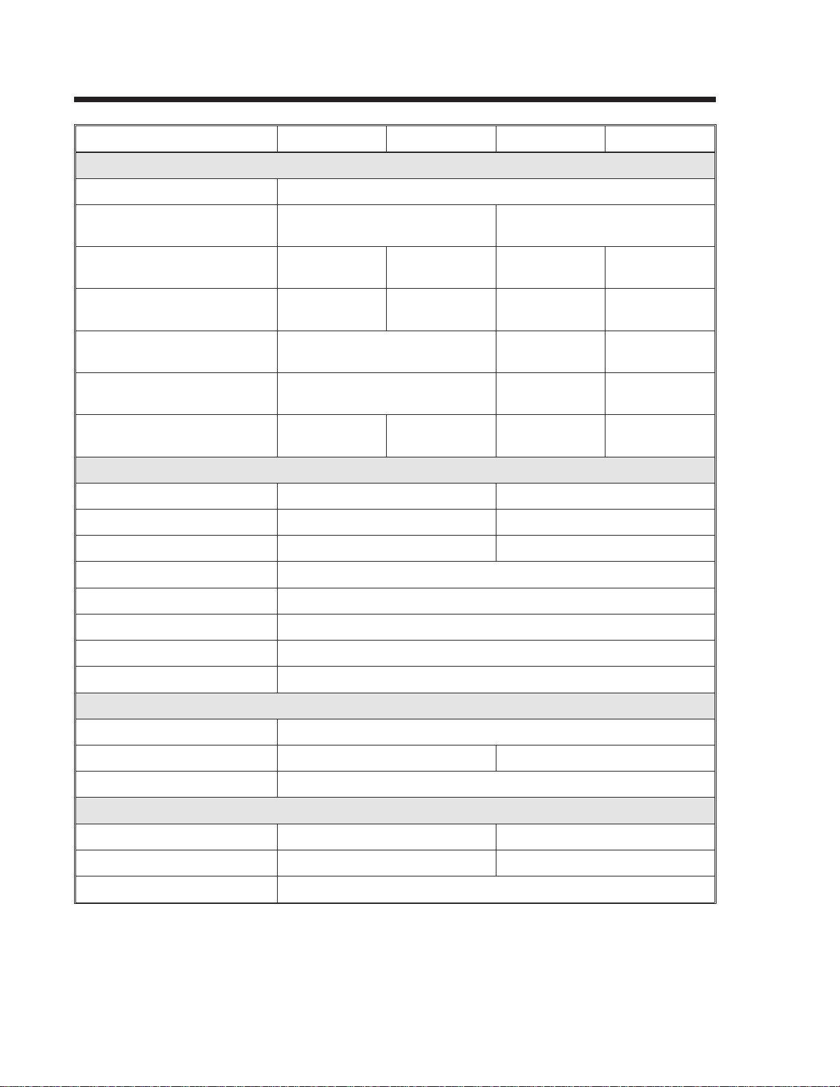
GENERAL PRINTER SPECIFICATIONS
SPECIFICATION CL408 CL412 CL608 CL612
PRINT
Method Direct or Thermal Transfer
Speed (User Selectable) 2 to 6 ips
50 to 150 mm/s
Print Module (Dot Size) .0049 in.
.125 mm
Resolution 203 dpi
8 dpmm
Maximum Print Width 4.1 in.
104 mm
Maximum Print Length
(Expanded Print Length)
Maximum Print Length
with 2MB Memory Card
MEDIA
Minimum Width .87 in. (22 mm) 1.96 in. (50 mm)
Minimum Length .24 in. (6 mm) .78 in. (20 mm)
Maximum Width 5.1 in. (131 mm) 7 in. (178 mm)
Type Die Cut Labels, Fan-Fold, Tag Stock or Continuous
Caliper .010 in. (.25 mm)
49.2 in.
1249 mm
14 in.
356 mm
.0033 in.
.083 mm
305 dpi
12 dpmm
32.8 in.
833 mm
.0049 in.
.125 mm
203 dpi
8 dpmm
6.0 in.
152 mm
14 in.
356 mm
49.2 in.
1249 mm
4 to 8 ips
100 to 200 mm/s
.0033 in.
.083 mm
305 dpi
12 dpmm
6.5 in.
164mm
14 in.
356mm
27.7 in.
704 mm
Roll OD (max) 8.6 in. (218 mm), Face-In Wind
Core ID (min) 1.5 in. (38 mm)
Core ID (Recommended) 3 in. (76 mm)
SENSING
See-Thru for labels or tags Movable
Reflective Eye-Mark Movable Fixed
Continuous Form Sensor not used
RIBBON
Maximum Width 4.4 in. (111 mm) 6.75 in. (172 mm)
Length 1475 ft. (450 m) 1345 ft (410 m)
Thickness 4.5 micron, Face-In Wind
All specifications subject to change without notice.
Page 1-29001035 Rev. E SATOCL SeriesPrinters
Page 13
Section 1. Printer Overview
SPECIFICATION CL408 CL412 CL608 CL612
CONTROLS AND SIGNALS
On-Line LED Status = Green
(1)
Power LED None Green
Media Out LED Status = Red
Ribbon Out LED Status = Red
Error LED Status = Red
(1)
(1)
(1)
LCD Panel 2 Line x 16 Character
On/Off-Line Switch Front Panel
Label Feed Switch Front Panel
Power On/Off Switch Rear Panel
POTENTIOMETER ADJUSTMENTS
Print Darkness Front Panel
Green
Red
Red
Red
Pitch Front Panel
Offset Front Panel
Display None Front Panel
INTERFACE CONNECTIONS
Parallel Centronics Compatible
Serial RS232C (2400 to 19.2K bps)
RS422/485 (2400 to 19.2K bps)
(2)
(2)
(2)
Serial Protocol Hardware Flow Control (Ready/Busy)
Software Flow Control (X-On/X-Off)
Bi-directional (ENQ/Response)
Data Transmission ASCII Format
PROCESSING
CPU 32 Bit RISC
ROM 1 MByte (2 x 4M bit)
DRAM 2 MByte
Programmable 8 KByte EEPROM
(1) Single two color (Red, Green) LED.
(2) Interface Adapter Card required.
All specifications subject to change without notice.
SATOCL Series Printers9001035 Rev. EPage 1-3
Page 14
Section 1. Printer Overview
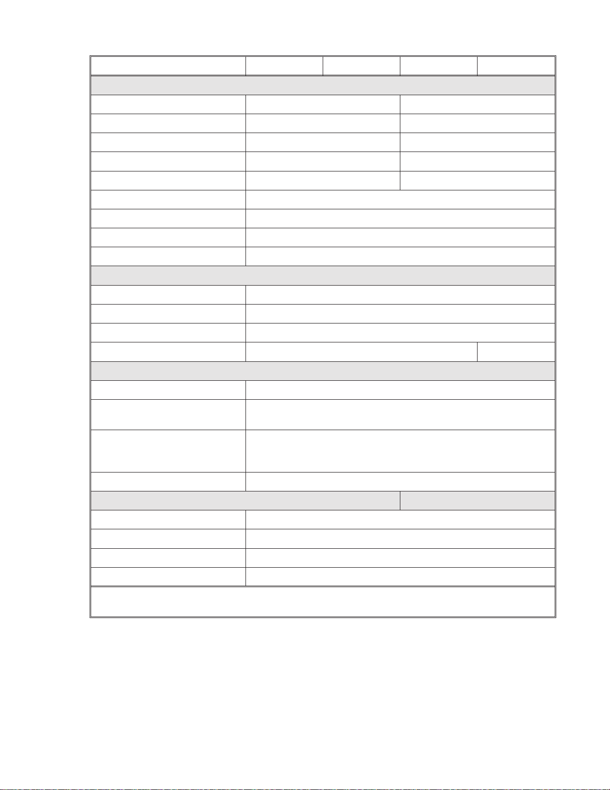
CHARACTER FONTS
SPECIFICATION CL408 CL608 CL412 CL612
MATRIX FONTS
U Font (5 dots W x 9 dots H)
S Font (8 dots W x 15 dots H)
M Font (13 dots W x 20 dots H)
XU Font (5 dots W x 9 dots H) Helvetica
XS Font (17 dots Wx 17 dots H) Univers Condensed Bold
XM Font (24 dots W x 24 dots H) Univers Condensed Bold
OA Font (15 dots W x 22 dots H) OCR-A (22 dots W x 33 dots H) OCR A
OB Font 20 dots W x 24 dots H) OCR-B (30 dots W x 36 dots H) OCR B
AUTO SMOOTHING FONTS
WB WB Font (18 dots W x 30 dots H)
WL WL Font (28 dot W x 52 dots H)
XB XB Font (48 dots W x 48 dots H) Univers Condensed Bold
XL XL Font (48 dot W x 48 dots H) Sans Serif
VECTOR FONT
Proportional or Fixed Spacing
Font Size 50 x 50 dots to 999 x 999 dots
Helvetica, 10 Font Variations
DOWNLOADABLE FONTS
TrueType Fonts with Optional Memory Card
CHARACTER CONTROL
Expansion up to 12X in either the X or Y coordinates
Character Pitch control
Line Space control
Journal Print facility
0°, 90°, 180° and 270° Rotation
All specifications subject to change without notice.
Page 1-49001035 Rev. ESATOCL SeriesPrinters
Page 15
Section 1. Printer Overview
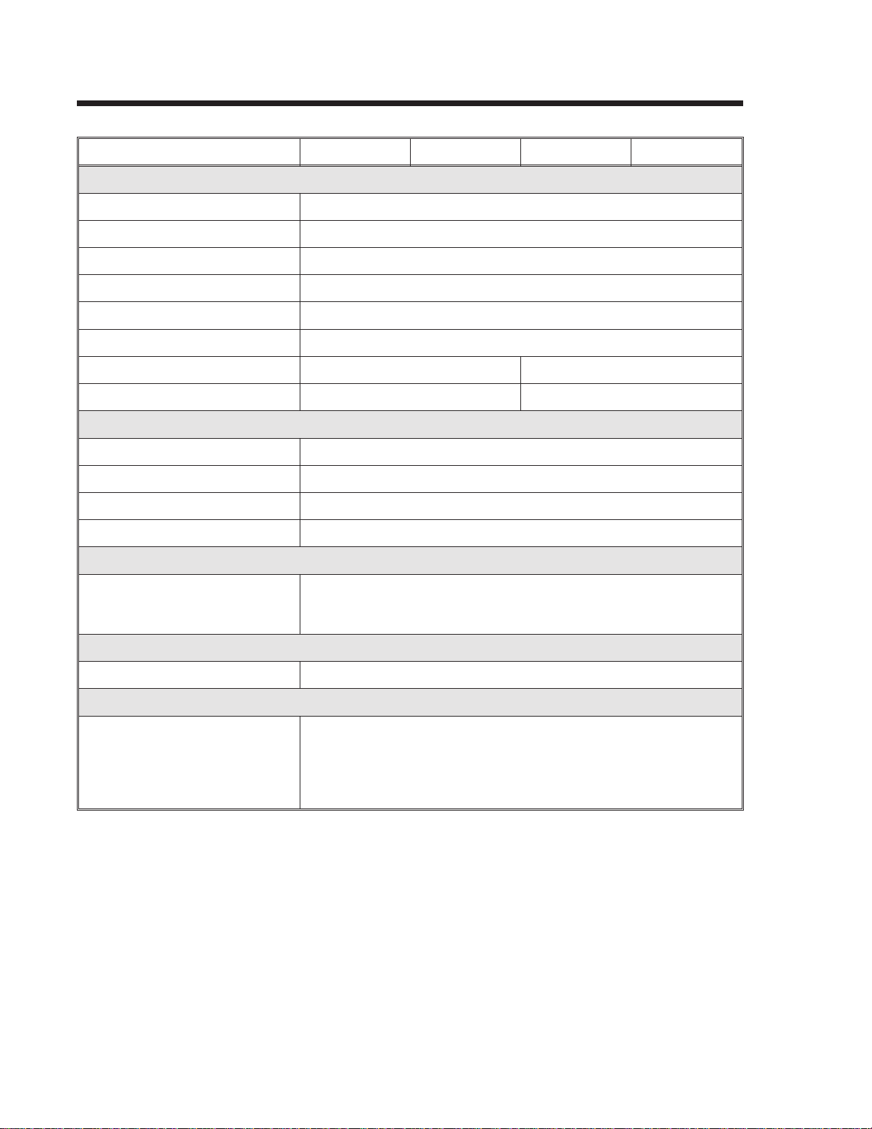
BAR CODES
SPECIFICATION CL408 CL608 CL412 CL612
SYMBOLOGIES
Bookland (UPC/EAN Supplemental)
EAN-8, EAN-13
CODABAR
Code 39
Code 93
Code 128
Interleaved 2 of 5
Industrial 2 of 5
Matrix 2 of 5
MSI
POSTNET
UCC/EAN-128
UPC-A and UPC-E
Data Matrix
Maxicode
PDF417
Ratios 1:2, 1:3, 2:5 User definable bar widths
Bar Height 4 to 600 dots, User programmable
Rotation 0°, 90°, 180° and 270°
OTHER FEATURES
Sequential Numbering Sequential numbering of both numerics and bar codes
Custom Characters RAM storage for special characters
Graphics Full dot addressable graphics, SATO Hex/Binary or .PCX formats
Form Overlay Form overlay for high-speed editing of complex formats.
All specifications subject to change without notice.
SATOCL Series Printers9001035 Rev. EPage 1-5
Page 16
Section 1. Printer Overview
PHYSICAL
SPECIFICATION CL408 CL412 CL608 CL612
DIMENSIONS
Wide 10.7 in. (271 mm) 13.8 in. (352 mm)
Deep 16.9 in. (430 mm) 16.9 in. (429 mm)
High 12.6 in. (321 mm) 11.7 in. (298 mm)
WEIGHT 28.7 lbs (13 Kg) 41.9 lbs (19 Kg)
POWER REQUIREMENTS
Voltage
Power Consumption 50W Idle
130W Operating
ENVIRONMENTAL
Operating Temperature 41° to 104°F (5° to 40°C)
Storage Temperature -0° to 104°F (-20° to 40°C)
Operating Humidity 15-85 % RH, non-condensing
Storage Humidity Max 90% RH, non-condensing
Electrostatic Discharge 8KV
REGULATORY APPROVALS
Safety UL, CSA
RFI/EMI FCC Class A
All specifications subject to change without notice.
110 V (±10 %)
220V (±10 %)
50/60 Hz (±1%)
50W Idle
210W Operating
Page 1-69001035 Rev. ESATOCL SeriesPrinters
Page 17
Section 1. Printer Overview
OPTIONAL ACCESSORIES
ACCESSORY CL408 CL412 CL608 CL612
MEMORY EXPANSION Two slots for PCMCIA Memory Cards (up to 2MB each). Can be used
for Graphic File storage, print buffer expansion, format storage and
downloaded TrueType fonts.
CALENDAR An internally mounted Date/Time clock that can be used to date/time
stamp labels at the time of printing.
LABEL CUTTER Internal attachment allowing labels to be cut at specified intervals.
Controlled through programming.
LABEL DISPENSER Internal attachment allowing
labels to be peeled from backing
for immediate (on demand)
application. Internal backing
take-up.
LABEL REWINDER External option rewinds labels onto a roll after they are printed.
PARALLEL INTERFACE Parallel I/F card must be installed.
SERIAL INTERFACE Serial I/F card must be installed.
COAX/TWINAX INTERFACE Coax/Triax I/F card must be
installed in the interface slot.
Coax I/F emulates an IBM
3287-2 printer with a standard
Type A BNC connector. Twinax
I/F emulates IBM 5224, 5225,
5226 or 4214 printers with
auto-terminate/cable-thru
capabilities.
All specifications subject to change without notice.
Internal attachment allowing
labels to be peeled from backing
for immediate (on demand)
application. Backing take-up
mounted externally to rear of
printer.
Coax/Twinax adapter card must
be installed. Coax I/F emulates
an IBM 3287-2 printer with a
standard Type A BNC connector.
Twinax I/F emulates IBM 5224,
5225, 5226 or 4214 printers with
auto-terminate/cable-thru
capabilities. Allows the
Centronics interface to remain
operational.
SATOCL Series Printers9001035 Rev. EPage 1-7
Page 18

Section 1. Printer Overview
This page left intentionally blank.
Page 1-89001035 Rev. ESATOCL SeriesPrinters
Page 19

INSTALLATION AND CONFIGURATION
INTRODUCTION
This section is provided to assist you in taking the CL Series Printer from the shipping
container to the application environment. Where the physical differences between the
printer models are significant (such as loading paper and ribbons), separate sections
for each of the models are used for clarity.
The following information is provided in this section:
SECTION 2.
• Unpacking and Parts Identification
• Setting Up the Printer
• Loading Labels or Tags
• Loading the Ribbon
• Operator Panel
• Printer Configuration
SATOCL Series Printers9001035 Rev. EPage 2-1
Page 20

Section 2. Installation and Configuration
UNPACKING AND PARTS IDENTIFICATION
Consider the following when unpacking the printer:
• The box should stay right-side up.
• Lift the printer out of the box carefully.
• Remove the plastic covering from the printer.
• For the CL4XX printers, remove the Front Access Door from its protective
bag and attach it to the printer.
• Remove the accessory items from their protective containers.
• If the printer has been stored in a cold environment, allow it to reach room
temperature before powering it on.
• Set the printer on a solid, flat surface. Inspect the shipping container and
printer for any signs of damage that may have occurred during shipping.
NOTE: The following illustrations are representative only. Your printer may not be
packed exactly as shown here, but the unpacking steps are similar.
CL4XX Packaging CL6XX Packaging
Page 2-29001035 Rev. ESATOCL SeriesPrinters
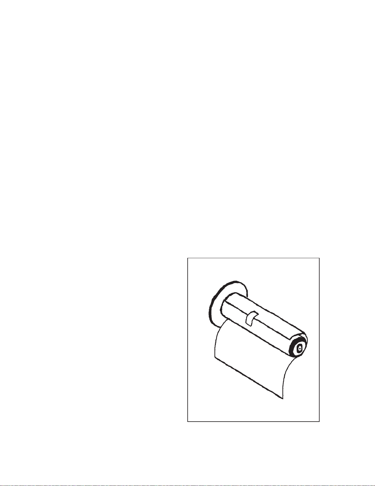
Page 21

Section 2. Installation and Configuration
Verify that you have the following materials when unpacking:
• Printer
• Power Cord
• Extra Ribbon Core
• Operator’s and Technical Reference Manual
CL Printer
Operator Manual
SETTING UP THE PRINTER
Consider the following when setting up the printer:
• Locate a solid flat surface with adequate room to set the printer. Make sure
there is enough room at the top and right-hand (facing the printer) side to
provide clearance for the label access door to swing open.
Power Cable
Extra Ribbon Core
• The location should be near the host computer or terminal. The maximum
distance for RS232 cables is 50 feet and six feet for Centronics Parallel
cables. Cables can be purchased locally, and their configuration will depend
upon the host system being used.
• For information on interfacing the printer to a host system, see
Section 5: Interface Specifications.
SATOCL Series Printers9001035 Rev. EPage 2-3
Page 22
Section 2. Installation and Configuration
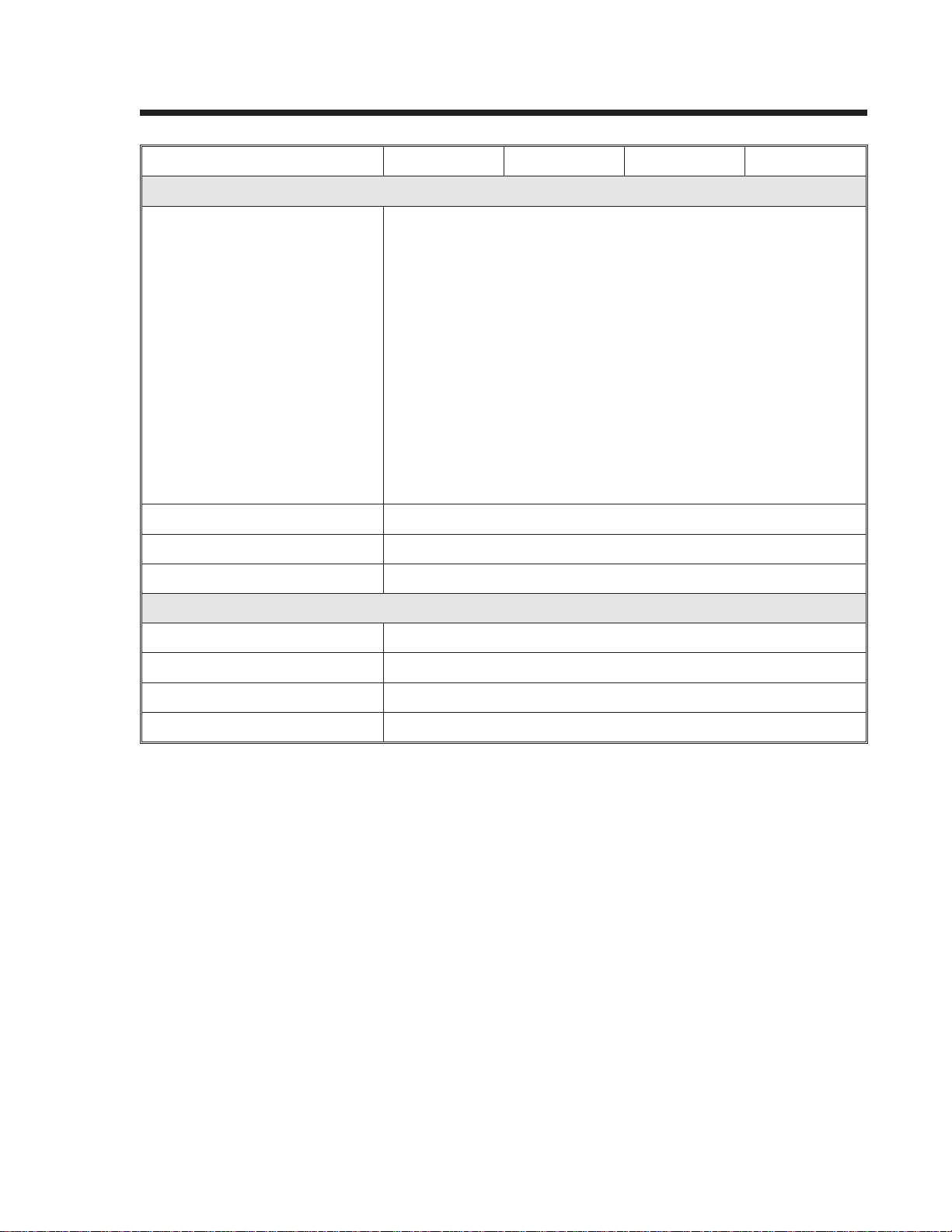
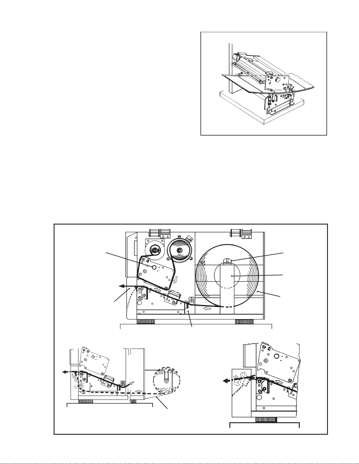
LOADING LABELS, TAGS AND RIBBON CL608 and CL612
LOADING LABELS OR TAGS
1. Open the Side Access Door by
swinging it up and to the left. The
hinge system automatically
dampens the movement to
prevent the door from
inadvertently falling and possibly
causing injury to the operator.
2. Open the Print Head Assembly
by pushing the Head Latch
toward the rear of the printer. The
Print Head Assembly is
spring-loaded and will
automatically open as soon as the
Head Latch is disengaged.
Head Latch
3. Push the Label Supply Guide to the outside of the printer to give the maximum
label width.
4. Release the Label Roll Support by pulling outward at the top and swing it down
and out of the way.
5. If using roll labels (or tags), load the roll onto the Label Supply Spindle so that
the printing side of the labels faces upwards as it unwinds from the roll. The
labels should be wound face-in. Push the roll all the way to the inside of the
printer and push the Label Supply Guide snugly against the outside of the
label roll.
6. If using fanfold labels (or tags) set them on a flat surface behind the printer. Pass
the labels (printing side up) through the slot and under the Label Supply
Spindle.
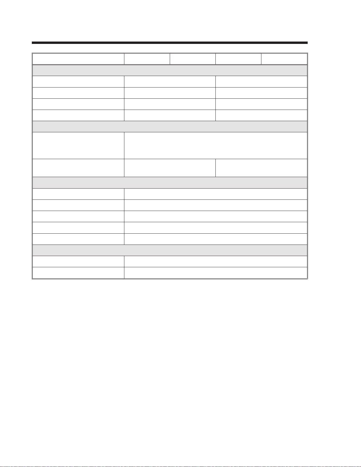
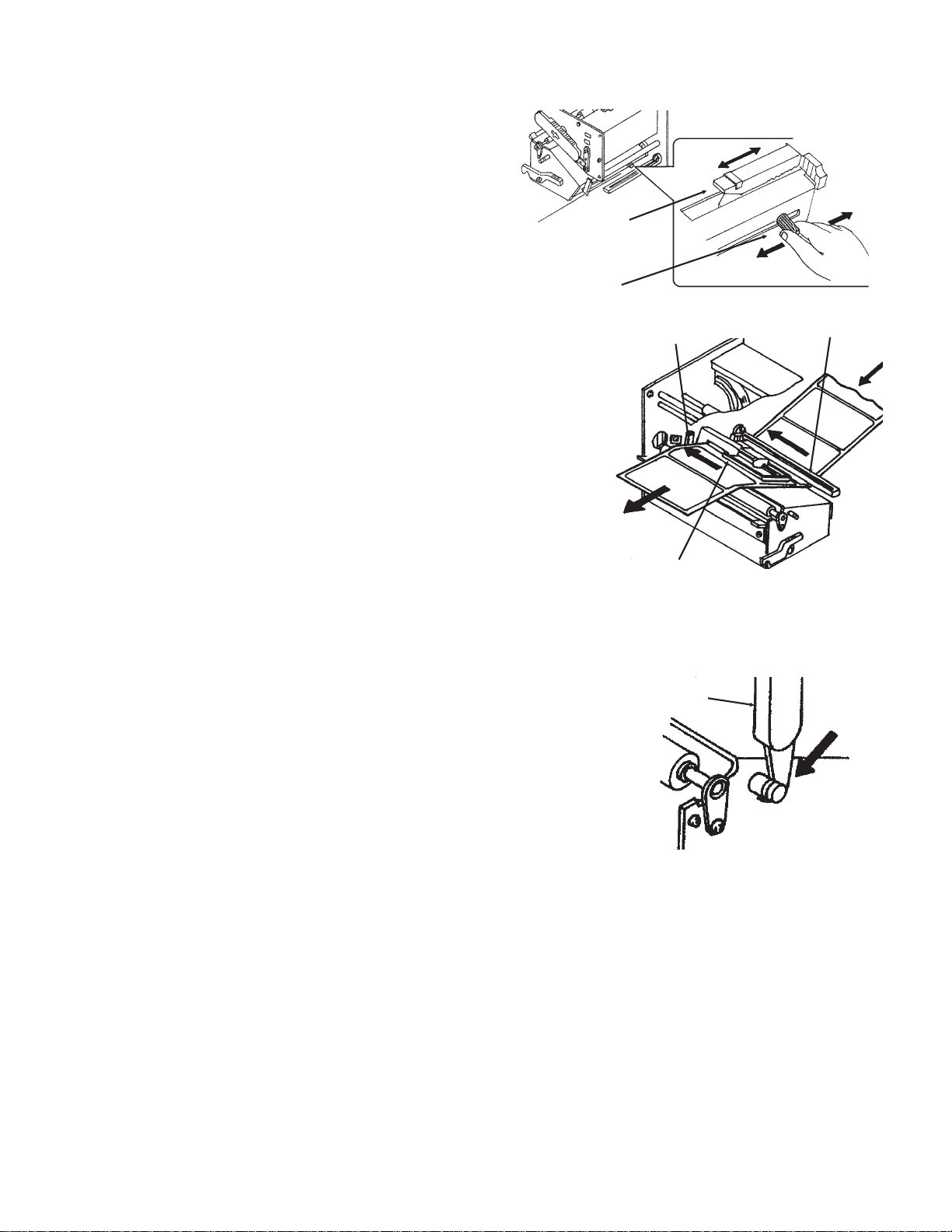
7. Open the Label Hold-Down by
squeezing the green tab and the
release tab together. The Label
Hold-down is spring loaded and
will open automatically when the
latch is disengaged. Feed the
Sensor Adjust
Cap Screw
Sensor Adjust
Tab
labels under the Label Guide,
under the Label Hold-Down,
through the Print Head
Assembly and out the front of
the printer.
8. Inspect the label routing and verify
that the path matches that
illustrated in the Label Loading
Label Hold-Down
diagram. Set the Adjustable
Page 2-49001035 Rev. ESATOCL SeriesPrinters
Page 23
Section 2. Installation and Configuration
Label Guide to keep the labels
against the inside of the printer.
9. Close the Label Hold-Down by
pushing downward on the green
tab until it latches closed.
NOTE: If the Label Dispenser option
has been purchased, see Appendix D,
for proper label routing instructions.
10. Adjust the Label Sensor
Assembly to the correct position
by loosening the Sensor Adjust
Cap Screw located on the front side of the Label Hold-Down and moving the
Sensor Adjust Tab to the correct position. After it is correctly positioned,
retighten the Sensor Adjust Cap Screw.
11. If the ribbon is already loaded, close the Print Head Assembly by pushing
downward on the green tab until it latches closed.
12. If the ribbon is not loaded, see the following description for loading instructions.
Media Knob
Printed Labels
Dispenser Routing
Label Guide
Cutter Routing
Label Supply
Guide
Label Roll
Support
Label Roll
Label Backing
SATOCL Series Printers9001035 Rev. EPage 2-5
Page 24
Section 2. Installation and Configuration
12. Adjust the Media Knob based on the media you have loaded. For media up to
2.3 inches wide, use the “1” position, for media between 2.3 and 4.6 inches wide,
use the “2” position. For media wider than 4.6 inches, use the “3” position. If you
use media narrower than 7 inches, using the wrong setting can void the print
head warranty due to the excessive pressure.
Caution: Using media narrower than the maximum print width may cause excess
head wear due to the label edge. See page 2-7 for precautions.
LOADING THE RIBBON
1. Open the Side Access Door by swinging it up and to the left. The hinge system
automatically dampens the movement to prevent the door from inadvertently
falling and possibly causing injury to the operator.
2. Open the Print Head Assembly by pushing the Head Latch toward the rear of
the printer. The Print Head Assembly is spring-loaded and will automatically
open as soon as the Head Latch is disengaged.
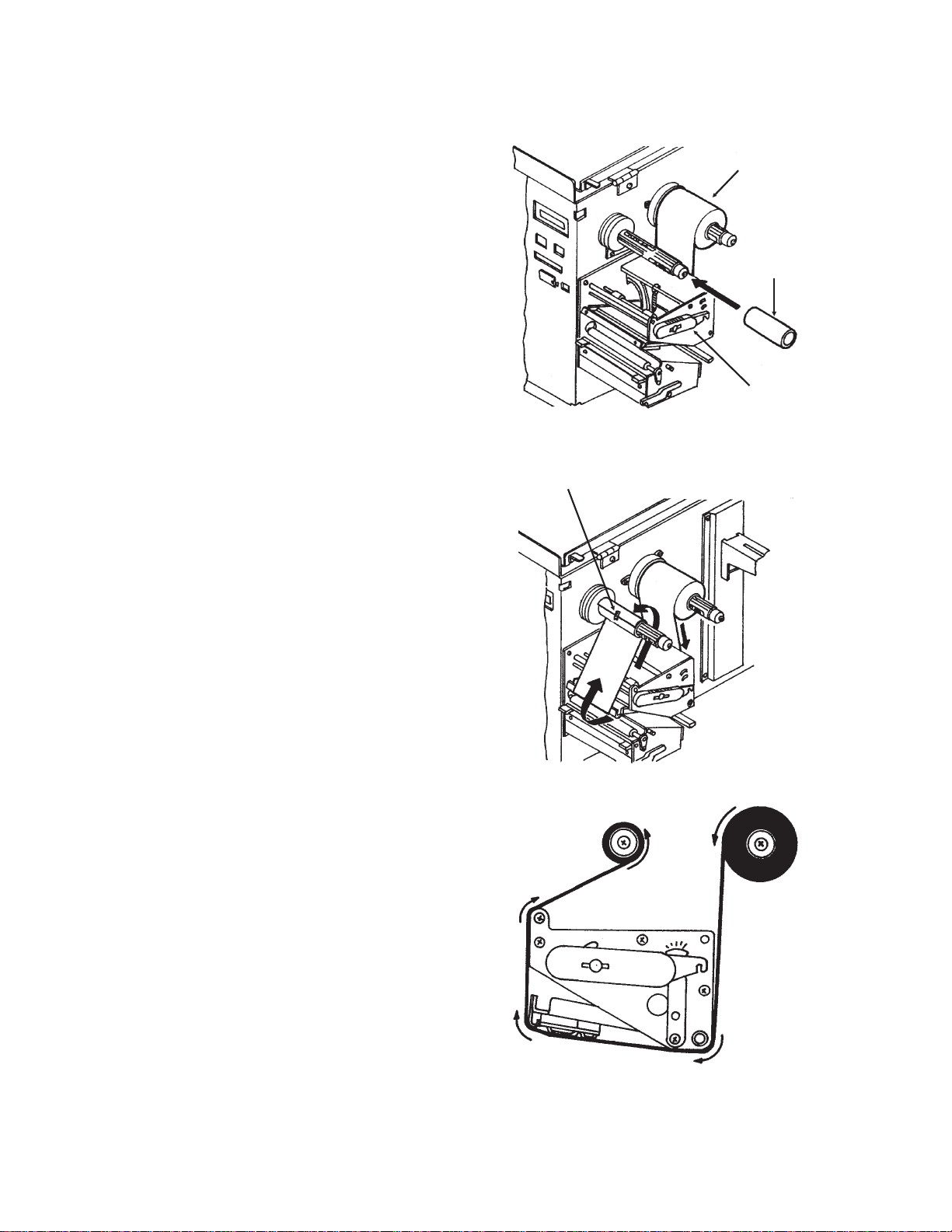
3. Locate the Extra Ribbon Core supplied with the printer. Place the core on the
Ribbon Rewind Spindle, pushing it all the way to the inside of the spindle.
Note that the new empty core of each subsequent roll becomes the next rewind core.
4. Load the ribbon onto the Ribbon Supply Spindle, also pushing it all the way to
the inside of the spindle. The dull side of the ribbon should be facing down as it
travels through the Print Head Assembly.
5. Feed the leader portion of the
ribbon through the Print Head
Assembly and up to the Ribbon
Rewind Spindle following the
routing shown in the diagram.
6. Load the ribbon behind and over the
top of the Ribbon Rewind
Spindle and tape it to the Extra
Ribbon Core. Make sure it
matches the ribbon path shown in
the diagram.
7. Manually turn the Rewind
Spindle to wrap the ribbon onto
the core one to two turns to
secure it.
8. If the labels or tags are already
loaded, close the Print Head
Assembly by pushing downward
on the green tab until it latches
closed.
Page 2-69001035 Rev. ESATOCL SeriesPrinters
Page 25
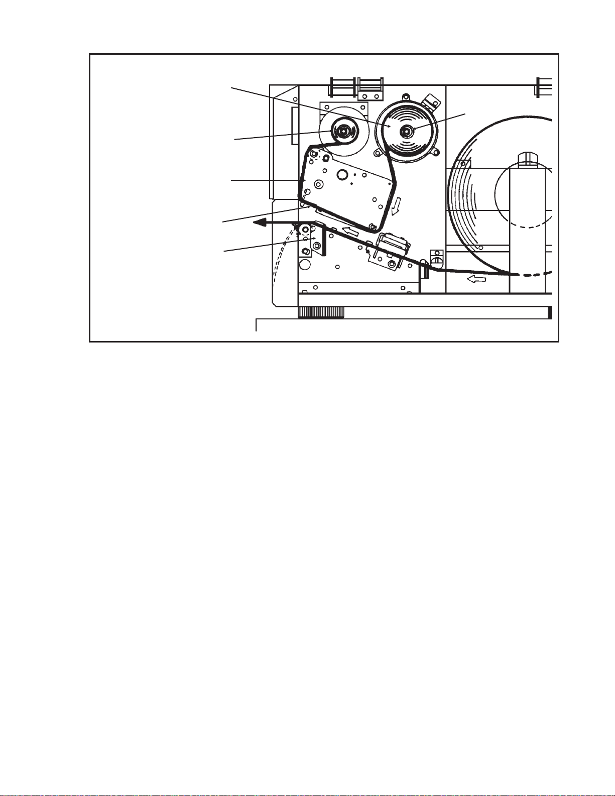
Ribbon Roll
Ribbon Rewind
Spindle
Print Head
Assembly
Ribbon Path
Head Latch
Section 2. Installation and Configuration
Ribbon Supply
Spindle
NOTE: Run a test print to ensure that the labels and ribbons were loaded correctly.
See the “User Test Print” section of this chapter on page 2-37 for instructions on
how to run test prints.
CAUTION: If your labels are less than the full width of the print head, the outside
edge will eventually wear out a small portion of the print head, resulting in an area
that will not print. Special care must be taken if you plan to use multiple widths of
labels, since the damaged portion of the print head caused from edge wear on a
more narrow label may affect the printing on a wider label. We suggest you plan
your print formats carefully to avoid using the area of possible damage on the print
head when using a wider label. The small area of damage will have no effect on
printing with the undamaged part of the print head.
Damage from a label edge is physical damage and is unavoidable. It is not covered
by warranty. It is possible to delay such damage by always ensuring that the ribbon
used is wider than the label stock. This will help to protect the print head from label
edge damage.
SATOCL Series Printers9001035 Rev. EPage 2-7
Page 26
Section 2. Installation and Configuration
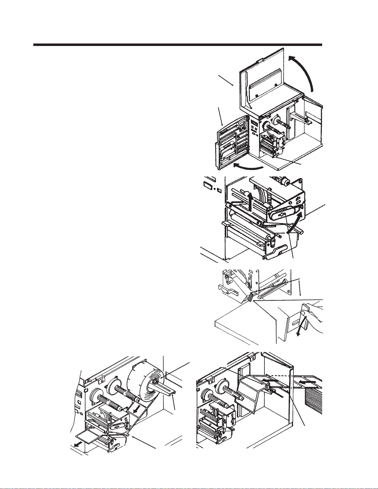
LOADING LABELS, TAGS AND RIBBON CL408 and CL412
LOADING LABELS AND TAGS
1. Open the Top Access Door by
swinging it up and to the left. Open
the Front Access Door by pushing
down on the green Front Cover Latch
and swinging the door forward and to
the left. This gives access to the print
mechanism on three sides
Note: The Top Access Door must be
open before the Front Access Door
can be opened.
2. Open the Print Head Assembly by
rotating the green Head Latch
counter clockwise. The head is spring
loaded and will automatically raise to
the opened position
3. Push the Label Supply Guide to the
outside of the printer to give the
maximum label width.
Top Access
Door
Front Access
Door
Front Access
Door Latch
4. Clear access is provided to the label path
by pulling the top of the Outside
Label Guide down.
5. If using roll labels (or tags), load the roll
onto the Label Supply Spindle so
that the printing side of the labels faces
upwards as it unwinds from the roll.
Push the roll all the way to the inside of
the printer, raise the Label Supply
Guide and adjust its position until it
fits snugly against the outside of the
label roll.
Label Supply
Label Supply
Spindle
Head Latch
Outside Label
Guide
Guide
Feed Slot
Outside Label Guide
Page 2-89001035 Rev. ESATOCL SeriesPrinters
Page 27
6. If using fanfold labels (or tags) set
them on a flat surface behind the
printer and remove the cover from
the Feed Slot on the rear panel.
Pass the labels (printing side up)
through the slot and over the
Label Supply Spindle.
7. Route the labels under the Label
Hold-Down, through the Label
Sensor Assembly, under the
Print Head and out the front of the
print mechanism. Push the labels all the way to
the inside of the printer until they touch the
Inside Label Guide.
Note: Make sure the labels are routed
through the Label Sensor Assembly. If they
are not, the printer will react as if there are
no labels loaded and will refuse to print.
Section 2. Installation and Configuration
Sensor
Assembly
Sensor
Adjust
Knob
Inside
Label Guide
Label Hold
Down
8. Adjust the Label Sensor Assembly loosening
the green Sensor Adjust knob located on the
bottom side of the Label Transport
Assembly and moving the assembly to the
correct position. After it is correctly positioned,
Sensor
Assembly
retighten the green Sensor Adjust knob.
9. Raise the Outside Label Guide to the closed
position and push the guide inward until it
barely contacts the outside edge of the labels.
Head Latch
10. If Ribbon is already loaded in the printer,
close the Print Head and latch it in the
down position.
11. Inspect the label routing and verify that the
path matches that illustrated in the Label
Loading diagram on the inside of the Top
Access Door.
12. Carefully feed several labels through the opening in the Front Access Door and
close it. After the Front Access Door is closed, the Top Access Door may be
closed. These covers have interlock switches and the printer will not operate if
either is open.
NOTE: If the Label Dispense Option has been purchased, see Appendix D, Optional
Accessories for instructions on how to route the label backing. For information on
how to enable this option, see the Printer Configuration section in this chapter.
SATOCL Series Printers9001035 Rev. EPage 2-9
Page 28
Section 2. Installation and Configuration
LOADING THE RIBBON
1. Open the Top and Front Access
Doors.
2. Open the Print Head Assembly by
rotating the green the Head Latch
counter clockwise. The print head is
spring loaded and will raise to the open
position as soon as the latch is released.
3. Locate the Extra Ribbon Core supplied
with the printer. Place the core on the
Ribbon Rewind Spindle, pushing it
all the way to the inside of the spindle.
Note that the new empty core of each
subsequent roll becomes the next rewind core.
4. Load the ribbon onto the Ribbon Supply Spindle, pushing it all the way to the
inside of the spindle. The dull side of
the ribbon should be facing down as it
travels through the Print Head
Assembly.
Ribbon Supply
Roll
Empty Core
Head Latch
Tape
5. Feed the leader portion of the ribbon
through the Print Head Assembly
and up to the Ribbon Rewind
Spindle following the routing shown
in the diagram.
6. Load the ribbon behind and over the top
of the Ribbon Rewind Spindle and
tape it to the Extra Ribbon Core.
Make sure it matches the ribbon path
shown in the diagram.
7. Manually turn the Ribbon Rewind
Spindle to wrap the ribbon onto the
core one to two turns to secure it.
8. If the labels or tags are already loaded,
close the Print Head Assembly by
rotating the green Head Latch
clockwise until it latches closed and
close the Front and Top Access
Doors.
NOTE: Run a test print to ensure that the
labels and ribbons were loaded correctly.
See the “User Test Print” section of this
chapter on page 2-37 for instructions on how to run test prints.
Page 2-109001035 Rev. ESATOCL SeriesPrinters
Page 29
Section 2. Installation and Configuration
Ribbon Roll
Ribbon Rewind
Spindle
Print Head
Assembly
Head Latch
CAUTION: If your labels are less than the full width of the print head, the outside
edge will eventually wear out a small portion of the print head, resulting in an area
that will not print. Special care must be taken if you plan to use multiple widths of
labels, since the damaged portion of the print head caused from edge wear on a
more narrow label may affect the printing on a wider label. We suggest you plan
your print formats carefully to avoid using the area of possible damage on the print
head when using a wider label. The small area of damage will have no effect on
printing with the undamaged part of the print head.
Ribbon Supply
Spindle
Ribbon Path
Label Supply
Spindle
Label Path
Damage from a label edge is physical damage and is unavoidable. It is not covered
by warranty. It is possible to delay such damage by always ensuring that the ribbon
used is wider than the label stock. This will help to protect the print head from label
edge damage.
LABEL SENSOR ADJUSTMENTS CL608 and CL612
The Gap (transmissive) sensor on the CL608 and CL612 can be adjusted over a
limited range. It is located in the Label Hold-Down Assembly and can be
adjusted by loosening the Sensor Adjust Cap Screw on the front of the Label
Hold-Down (see page 2-5) and sliding the Sensor Adjust Tab to the desired
position. The Gap sensor can be adjusted from a minimum of 1.0 in. (25mm) to a
maximum of 3.5 in. (90mm). The Eye Mark sensor is fixed at 0.33 in. (9mm).
LABEL SENSOR ADJUSTMENTS CL408 and CL412
Both the Eye-Mark (refelective)and Gap (transmissive) sensors on the CL408 and
CL412 can be adjusted over a limited range. They are both located in the Label
Sensor Unit. The assembly can be adjusted by loosening the green Sensor Adjust
knob located underneath the Label Transport Assembly (see page 2-9) and
sliding the Label Sensor Unit to the desired position. The Gap sensor can be
adjusted from a minimum of 0.67 in. (17mm) to a maximum of 2.5 in. (64 mm), and
SATOCL Series Printers9001035 Rev. EPage 2-11
Page 30
Section 2. Installation and Configuration
the Eye-Mark from a minimum of 0.25 in. (6mm) to a maximum of 2.1 in. (53mm).
See page 2-21 for sensor position range.
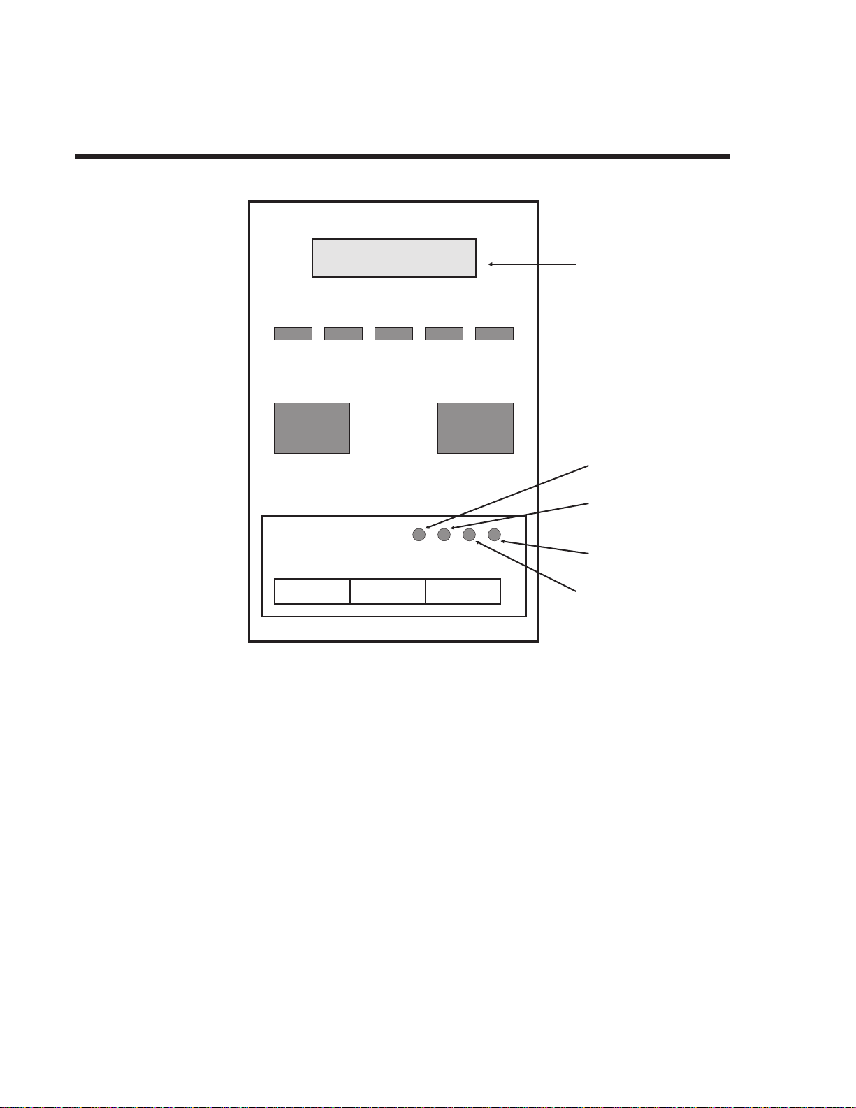
OPERATOR PANEL CL608 and CL612
LCD
DISPLAY
PANEL
LINE LABEL RIBBON ERRORPOWER
LINE FEED
DISPLAY
PITCH
PRINT
Reserved
DSW2 DSW3
OFFSET
The CL608/CL612 Operator Panel consists of five LED indicators, two
momentary contact switches, three DIP switches, four adjustment potentiometers and
one LCD Display. All of these are accessible from the front of the printer. They are
used to set the printer operating parameters and to indicate the status of the printer
to the operator. After you power on the printer, familiarize yourself with the keys and
indicators as it will help you understand the configuration process.
PRINT: Potentiometer to adjust print darkness (fine tuning).
OFFSET: Potentiometer to adjust amount of back/forward feed
for dispenser/cutter/tear-off bar position (+/-3.75 mm)
PITCH: Potentiometer to adjust home position of the label
(+/- 3.75 mm). Affects stop position of label feed, print
position and dispense position.
DISPLAY: Potentiometer to adjust the contrast of the LCD.
POWER: LED, illuminated when the power is on.
Page 2-129001035 Rev. ESATOCL SeriesPrinters
Page 31

Section 2. Installation and Configuration
LABEL: LED, illuminated when label supply is out.
RIBBON: LED, illuminated when ribbon motion sensor does not
detect any ribbon motion.
ERROR: LED, illuminated when there is a system fault such as
an open print head.
ONLINE: LED, illuminated when printer is ready to receive data.
It is turned on and off by toggling the LINE key. This
indicator will blink while the printer is receiving data.
LINE: Momentary switch. Pressing this key toggles the
printer between the on-line and off-line mode. When
the printer is on-line, it is ready to receive data from
the host. This key acts as a pause during a print job by
taking the printer off-line. It can also be used as a
Pause
function key to stop label during the printing
process.
FEED: Momentary switch. Pressing this key feeds one blank
label through the printer when it is off-line. When the
printer is on-line, another copy of the last label will be
printed.
DSW2-3: Located behind the Front Access Door. DIP switch
array to set operational parameters of the printer.
DSW1 is used to set the RS232 parameters and is
located on the RS232 interface board.
LCD: 2 Line x 16 Character LCD display. Used for setting
operational parameters of the printer.
SATOCL Series Printers9001035 Rev. EPage 2-13
Page 32

Section 2. Installation and Configuration
OPERATOR PANEL CL408 and CL412
LCD
DISPLAY
PANEL
TWO-COLOR
STATUS LED
LINE FEED
OPTION
CONNECTOR
xxx
PITCHOFFSETPRINT
DSW2 DSW3
x
LABEL TAKEN
THRESHOLD
ADJUST
LABEL
TAKEN LED
Note: DSW1 (RS232 Parameter Select) is located on the RS232 Interface Board.
The CL408/412 Operator Panel consists of one two-color (red and green) LED
indicator, two momentary contact switches, two DIP switches (a third is located on
the RS232 interface card), four adjustment potentiometers and one LCD Display. All
of these are accessible from the front of the printer, however some are not accessible
unless the front cover is open. They are used to set the printer operating parameters
and to indicate the status of the printer to the operator. After you power on the
printer, familiarize yourself with the keys and indicators as it will help you
understand the configuration process.
PRINT: Located behind the Front Access Door. Potentiometer
to adjust print darkness (fine tuning).
OFFSET: Located behind the Front Access Door. Potentiometer
to adjust amount of back/forward feed for
dispenser/cutter/tear-off bar position (+/- 3.75 mm)
PITCH: Located behind the Front Access Door. Potentiometer
to adjust home position of the label (+/- 3.75 mm).
Affects stop position of label feed, print position and
dispense position.
Page 2-149001035 Rev. ESATOCL SeriesPrinters
Page 33

Section 2. Installation and Configuration
STATUS: Two-color (Red, Green) LED that indicates the
following status conditions:
Green - Illuminated when printer is ready to receive
data. It is turned on and off by toggling the LINE key.
Red -Illuminated when there is a system fault such as
an open print head.
LINE: Momentary switch. Pressing this key toggles the
printer between the on-line and off-line mode. When
the printer is on-line, it is ready to receive data from
the host. This key acts as a pause during a print job by
taking the printer off-line. It can also be used as a
Pause
function key to stop label during the printing
process.
FEED: Momentary switch. Pressing this key feeds one blank
label through the printer when it is off-line. When the
printer is on-line, another copy of the last label will be
printed.
DSW2-3: Located behind the Front Access Door. DIP switch
array to set operational parameters of the printer.
DSW1 is used to set the RS232 parameters and is
located on the RS232 interface board.
LCD: 2 Line x 16 Character LCD display. Used for setting
operational parameters of the printer.
LABEL TAKEN
THRESHOLD:
Located behind the Front Access Door. This
potentiometer is used to adjust the sensing level of the
Label Taken Sensor. Active only when the Label
Dispense option is installed.
OPTION CONNECTOR: Located behind the Front Access Door. This connector
is used for the cutter and dispenser optional
accessories.
LABEL TAKEN: Located behind the Front Access Door. This LED is
illuminated when a label is not present in the Label
Taken Sensor. If it is not illuminated, a label has been
detected in the sensor and printing will be inhibited
until it is removed. This LED is active only when the
Label Dispense option is installed. It is used to adjust
the Label Taken Sensor threshold.
SATOCL Series Printers9001035 Rev. EPage 2-15
Page 34

Section 2. Installation and Configuration
REAR PANEL CL608 and CL612
Power On/Off Switch: Turns power On or Off.
AC Input: Input 115V 50/60 Hz connector. Use the cable
provided.
AC Fuse: Input power protection. Type 3A/250V.
Interface Slot: Slot to plug in an interface adapter. An adapter must
be connected before the printer is operational.The
adapter types available are:
RS232C serial port, DB-25P.
Centronics parallel port, AMP 57-40360.
Memory Card Slot: Two connectors for optional PCMCIA Memory Cards.
EXT: External signal connector, AMP 57-60140.
Cover Plate
Remove for access to Dispenser
and Fan-Fold Slots
PCMCIA Memory
Expansion slots
I/F Module
Centronics Shown
Power Switch
AC Fuse
External Accesory
Connector
AC Power Input
Connector
Page 2-169001035 Rev. ESATOCL SeriesPrinters
Page 35

Section 2. Installation and Configuration
REAR PANEL CL408 and CL412
Power: Switch to turn power On or Off.
AC Input: Input 115V 50/60 Hz connector. Use the cable
provided.
AC Fuse: Input power protection. Type 3A/250V.
Interface Slot: Slot to plug in an interface adapter. An adapter must
be connected before the printer is operational.The
adapter types available are:
RS232C serial port, DB-25P.
Centronics parallel port, AMP 57-40360.
Memory Card Slot: Two slots for optional PCMCIA Memory Cards.
EXT: External signal connector for Accessories, AMP
57-60140.
Cover Plate
Remove for access to
Fan-Fold Slots
I/F Module
Centronics Shown
External Accesory
Connector
PCMCIA Memory
Expansion slots
Power Switch
AC Fuse
AC Power Input
Connector
SATOCL Series Printers9001035 Rev. EPage 2-17
Page 36

Section 2. Installation and Configuration
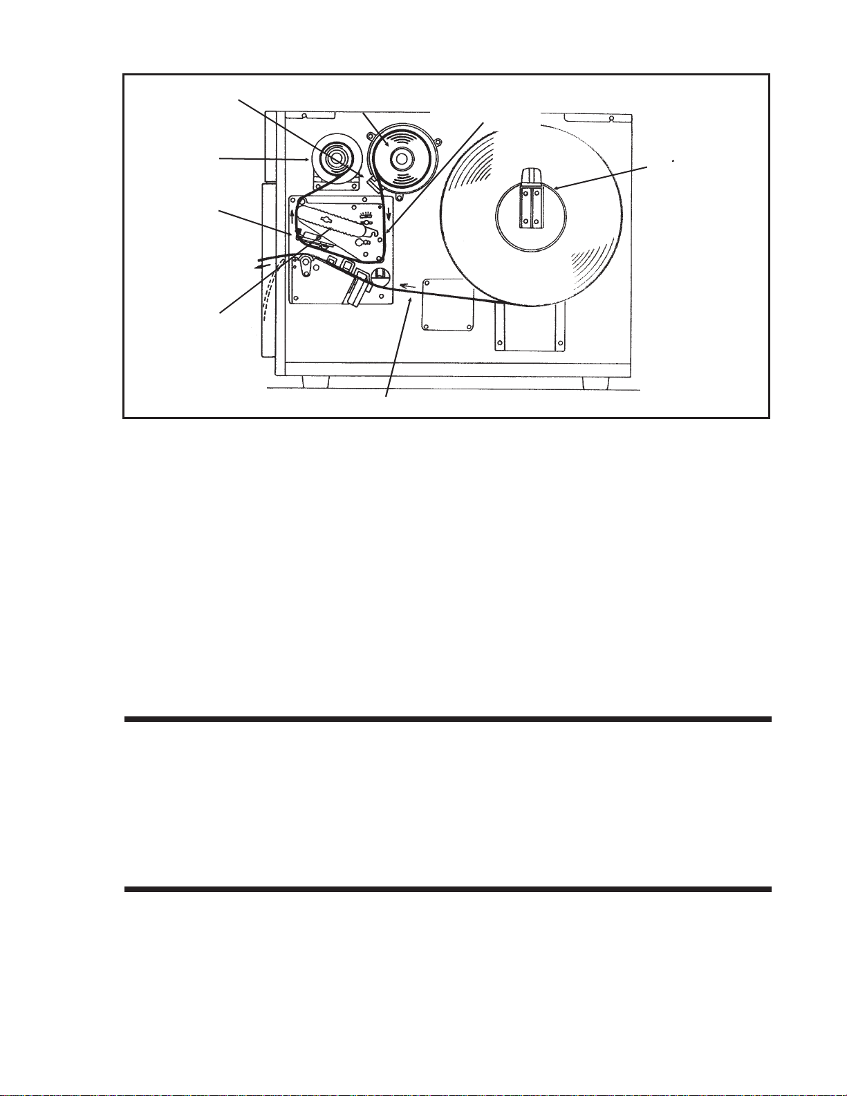
SWITCHES AND SENSORS CL608 and CL612
Ribbon End Sensor: This sensor is a motion detector that signals the printer
when the ribbon supply is turning.
Head Open Switch: When the print head is opened, this switch is activated
and the printer will stop printing.
Label Sensor Unit: This sensor unit contains two types of sensors, one for
label gap and one for Eye-Mark sensing. The label
sensors on the CL608 and CL612 are fixed and are
not adjustable.
Ribbon
Motion
Sensor
Label Sensor
Unit
Backing
Paper Inside
Edge
Miminum Eye-Mark Size
.12 in (3 mm) W x .24 in. (6 mm) L
0.33" (9 mm) Eye-Mark Sensor
1.0" (25 mm) to 3.5" (90 mm)
Label Gap Sensor
Label Inside Edge
Label
Feed
Direction
Min. Inter-Label Gap
0.12" (3 mm)
CL608 and CL612 Label Sensor Positioning
Page 2-18 9001035 Rev. D SATO CL Series Printers
Page 37

Section 2. Installation and Configuration
SWITCHES AND SENSORS CL408 and CL412
Ribbon End Sensor: This sensor is a motion detector that signals the printer
when the ribbon supply is turning.
Head Open Switch: When the print head is opened, this switch is activated
and the printer will stop printing.
Label Sensor Unit: This sensor unit contains two types of sensors, one for
label gap and one for Eye-Mark sensing. The sensors
are adjustable over a limited range.
Top Access Door
Interlock:
Front Access Door
Interlock:
Top Access
Door
Interlock
Front Access
Door Interlock
Switch
This switch prevents printer operation when the Top
Access Door is open.
This switch prevents printer operation when the Front
Access Door is open. The Top Access Door must be
open before the Front Access Door can be opened or
closed.
Ribbon
Motion
Sensor
Miminum Eye-Mark Size
.12 in (3 mm) W x .24 in. (6 mm) L
Label
Inside Label Guide
Backing
Paper Inside
Edge
0.25" to 2.1" (6 mm to 53mm)
Eye-Mark Sensor
Minimum
Inter-Label Gap
0.12" (3 mm)
0.67" to 2.5" (17mm to 64mm)
Label Gap Sensor
Note: These positions are different
from the M84XX printers.
Label Inside Edge
Feed
Direction
CL408 and CL412 Label Sensor Positioning
SATOCL Series Printers9001035 Rev. EPage 2-19
Page 38

Section 2. Installation and Configuration
PRINTER DIP SWITCH CONFIGURATION ALL MODELS
DIP Switch Panels
There are three DIP switches (DSW1, DSW2 and DSW3). On the CL608 and the
CL612, DSW2 and DSW3 are located underneath a flip-down cover of the front
panel. DSW1 (used to set the RS232 parameters) is located on the Serial Interface
board and the board must be removed to change the settings. DSW2 and DSW3 are
located behind the Front Access Door on the CL408 and CL412. These switches can
be used to set:
• RS232C transmit/receive parameters
• Thermal transfer or direct thermal mode
• Label sensor enable/disable
• Head check mode
• Hex dump mode
• Receive buffer size
• Operation mode
Each switch is an eight section “toggle” switch. The ON position is always to the top.
To set the switches, first power the unit Off, then position the DIP switches. Finally,
after placing the switches in the desired positions, power the printer back on. The
switch settings are read by the printer electronics during the power up sequence.
They will not become effective until the power is cycled.
RS232 Transmit/Receive Setting
Data Bit Selection (DSW1-1). This switch sets the printer to receive either 7 or 8
DSW1
DSW1-1 SETTING
Off 8 data bits
On 7 data bits
ON
OFF
12345678
bit data bits for each byte transmitted. Located on RS232 Interface Card.
DSW1-2 DSW1-3 SETTING
Off Off No Parity
Off On Even
On Off Odd
On On Not Used
ON
OFF
12345678
DSW1
Parity Selection (DSW1-2, DSW1-3). These switches select the type of parity
used for error detection.
Page 2-209001035 Rev. ESATOCL SeriesPrinters
Page 39

Section 2. Installation and Configuration
Stop Bit Selection (DSW1-4). Selects the number of stop bits to end each byte
transmission.
DSW1-4 SETTING
Off 1 Stop Bit
On 2 Stop Bits
ON
OFF
12345678
DSW1
Baud Rate Selection (DSW1-5, DSW1-6). Selects the data rate (bps) for the
RS232 port.
DSW1-5 DSW1-6 SETTING
Off Off 9600
Off On 19200
On Off 4800
On On 2400
ON
OFF
12345678
DSW1
Protocol Selection (DSW1-7, DSW1-8). Selects the flow control and status
reporting protocols. See Section 5: Interface Specifications for more information.
DSW1-7 DSW1-8 SETTING
Off Off Rdy/Bsy
Off On Xon/Xoff
On Off Bi-Com
On On Not Used
ON
OFF
12345678
DSW1
Printer Set Up
Print Mode Selection (DSW2-1). Selects between direct thermal printing on
thermally sensitive paper and thermal transfer printing using a ribbon.
DSW2-1 SETTING
Off Therm Xfr
On Direct Therm
ON
OFF
12345678
DSW2
Sensor Type Selection (DSW2-2). Selects between the use of a label gap or a
reflective Eye-Mark detector. See page 2-10 for the location of these sensors.
DSW2-2 SETTING
Off Gap
On Eye-Mark
ON
OFF
12345678
DSW2
Head Check Selection (DSW2-3). When selected, the printer will check for head
elements that are electrically malfunctioning.
DSW2
DSW2-3 SETTING
Off Disabled
On Enabled
ON
OFF
12345678
SATOCL Series Printers9001035 Rev. EPage 2-21
Page 40

Section 2. Installation and Configuration
Hex Dump Selection (DSW2-4). Selects Hex Dump mode (see page 2-20).
DSW2-4 SETTING
Off Disabled
On Enabled
ON
OFF
12345678
DSW2
Receive Buffer Selection(DSW2-5). Selects the operating mode of the receive
buffer. See Section 5: Interface Specifications for more information.
DSW2-5 SETTING
Off Single Job
On Multi Job
ON
OFF
12345678
DSW2
Protocol Code Selection (DSW2-7). Selects the command codes used for
protocol control. Refer to page 4-2 for more information.
DSW2-7 SETTING
Off Standard
On Non-Std
ON
OFF
12345678
DSW2
M84XX Emulation Mode (DSW2-8). For emulating special M84XX series
software. Should be used only if problems are encountered when using existing
M84XX software.
DSW2-8 SETTING
Off Off
On Suppress
ON
OFF
12345678
DSW2
Mode Selection (DSW3-1 and DSW3-2). Selects the operating mode of the
printer. Batch/Continuous disables the label sensors.
DSW3-1 DSW3-2 SETTING
Off Off Batch/Continuous
Off On Tear Off
On Off Cutter
On On Dispenser
ON
OFF
12345678
DSW3
Label Sensor Selection (DSW3-3). Enables or disables the Label Sensor. If the
Sensor is enabled, it will detect the edge of the label and position it automatically. If
it is disabled, the positioning must be under software control using Line Feed
commands.
DSW3-3 SETTING
Off Sensor Used
On Not Used
Page 2-229001035 Rev. ESATOCL SeriesPrinters
ON
OFF
12345678
DSW3
Page 41

Section 2. Installation and Configuration
Back-Feed Selection (DSW3-4). When Back-Feed is enabled, the printer will
position the label for dispensing/cutting and retract it before printing the next label.
See page 2-19 for information on setting the amount of offset.
DSW3
DSW3-4 SETTING
Off Disabled
On Enabled
ON
OFF
12345678
External Signal Interface. See Section 5: Interface Specifications for information
on the External Signals.
EXT Print Start Signal Selection (DSW3-5). Allows an external device to
initiate a label print. See page 5-10 for a description of signal requirements.
Note: This switch must be in the On position if a VeriScan is used to control the
printer via the EXT connector.
DSW3-5 SETTING
Off Disabled
On Enabled
ON
OFF
12345678
DSW3
External Signal Type Selection (DSW3-6, DSW3-7). Selects the type of
output signal. See page 5-11 for a definition of signal types.
DSW3-6 DSW3-7 SETTING
Off Off Type 4
Off On Type 3
On Off Type 2
On On Type 1
ON
OFF
12345678
DSW3
Repeat Print via External Signal (DSW3-8). Allows an external device to
control the reprint of the label in the print buffer. See page 5-10 for a description of
the signal requirements.
DSW3-8 SETTING
Off Disabled
On Enabled
ON
OFF
12345678
DSW3
Reserved for Future Use (DSW2-6)
Note: The Centronics (Parallel) communications port on the CL608 and CL612 is
always enabled regardless of the settings for the RS232 port. There are no settings
for Centronics! Both the Centronics and RS232 ports are active at all times. Care
should be taken to ensure that data is not transmitted to both ports simultaneously
as the received message will be corrupted.
SATOCL Series Printers9001035 Rev. EPage 2-23
Page 42

Section 2. Installation and Configuration
Default Settings
Switch Selections - All switches are placed in the Off position (default) for shipping.
This will result in the following operating configuration:
Communications:
Protocol:
Sensor:
Receive Buffer:
Mode:
Label Sensor:
Backfeed:
External Signals:
Software Default Settings - The printer stores the software settings upon receipt and
uses them until they are again changed by receipt of a command containing a new
setting. These settings are stored in non-volatile RAM and are not affected by
powering the printer off. The printer may be reset to use the default software settings
by depressing the LINE and FEED keys simultaneously while powering the printer
on. This will result in the following default configuration:
Print Darkness “2” “3”
Print Speed 6 in. per sec. 4 in. per sec.
Print Reference Vertical = 0001, Horizontal = 0001
Zero Slash
(1)
(1)
8 data bits, no parity, 1 Stop bit, 9600 Baud
Ready/Busy
Gap Sensor
Single Job
Batch/continuous
Sensor Used
Disabled
Disabled
CL608 and CL612 CL408 and CL412
(1) Active only if an RS232
Interface Card is installed.
Auto On Line Enabled
Once the default operation is completed, a “SATO DEFAULT COMPLETED” message
will be displayed on the LCD panel or a single “beep” will be heard if the printer does
not have an LCD panel. The printer should be powered off while this message is being
displayed (or after the “beep” is heard. This saves the default settings in the EEPROM
where they will be automatically loaded the next time the printer is powered on.
PRINTER ADJUSTMENTS
The LCD Panel is used in conjunction with the LINE and FEED switches by the
operator to manually enter printer configuration settings. Many of the settings can
also be controlled via software commands and in the case of conflict between
software and control panel settings, the printer will always use the last valid setting.
If you load a label job that includes software settings and then enter a new setting via
the Operation Panel, the manually set values will be used by the printer. If you set
the values manually and then download a job with software settings, the software
settings will be used.
SATO DEFAULT
COMPLETED
Page 2-249001035 Rev. ESATOCL SeriesPrinters
Page 43

POWER ON
Normal/User Mode
POWER
Print Test Labels
POWER + FEED
Advanced Mode Settings and Adjustments
POWER + LINE
Section 2. Installation and Configuration
ON LINE
QTY:000000
Page 2-28
USER TEST PRINT
LARGE SMALL
Page 2-37
ADVANCED MODE
SETUP
Page 2-31
Load SATO Default Settings
POWER + FEED + LINE
Download User Defined Protocol Codes
POWER + LINE + DSW2-7=ON
Reset to SATO Default Protocol Codes
POWER + LINE + FEED + DSW2-7=ON
Print Hex Dump Label
POWER , then DSW2-4=ON
SATO DEFAULT
COMPLETED
Page 2-26
USER DOWNLOAD
Page E-2
ALT PROTOCOL
DEFAULT COMPLETE
Page E-2
Print Buffer
Hex Dump Label
Page 2-44
Print Hex Dump Label
POWER + DSW2-4=ON
SATOCL Series Printers9001035 Rev. EPage 2-25
Receive Buffer
Hex Dump Label
Page 2-44
Page 44

Section 2. Installation and Configuration
Normal Mode
When the printer is powered on, the readout should display the following message:
ON LINE
The LCD Panel will display the Online status on the top line of the display and the the
bottom line will contain the label quantity (QTY) status. The ON LINE message will
be changed to OFF LINE whenever the printer is switched offline by depresing the
LINE key. As soon as a print job is received, the QTY message will indicate the
number of labels to be printed. As soon as the label job begins to print, the display
will indicate the number of labels remaining in the print job that remain to be printed.
User Mode
To enter the USER mode:
1. The printer is first taken offline by pressing the LINE key once. The display will
change to:
QTY:000000
OFF LINE
000000
2. When the display changes to OFF LINE, press the FEED and LINE keys
simultaneoulsy for more than one second.
The printer now displays the first USER mode adjustment (Print Darkness).
Print Darkness Setting
There are three Darkness (or heat range) settings on the CL608/612 (1, 2 and 3)
and five on the CL408/412 (1, 2, 3, 4, and 5). The higher numbers represent darker
settings. The current setting is indicated by an underline under one of the range
settings. To change the setting:
PRINT DARKNESS
1(L)
1. Use the LINE key to step the underline cursor to the desired setting.
2. Once the correct setting is underlined, press the FEED key to accept the setting and
advance to the next adjustment.
2(M) 3(D)
Note: This setting can be overriden by software (see Print Darkness page 4-56).
After setting the heat range with this command, finer adjustments can be made using
the PRINT potentiometer adjustment on the Adjustment panel. See Section 3:
CLEANING AND MAINTENANCE, for additional information on how to make this
adjustment for optimum print quality.
Page 2-269001035 Rev. ESATOCL SeriesPrinters
Page 45

Section 2. Installation and Configuration
Print Speed Adjustment
There are three SPEED settings on the CL608/612 (4 ips, 6 ips and 8 ips) and five on
the CL408/412 (2 ips, 3 ips, 4 ips, 5 ips and 6 ips). The setting is listed on the bottom
line of the display. The current setting is indicated by an underline under one of the
speed settings. To change the setting:
PRINT SPEED
4
CL408 CL412 CL608 CL612
Print Speed
Setting
1. Use the LINE key to step the underline cursor to the desired speed setting.
2. Once the correct setting is underlined, press the FEED key to accept the setting and
advance to the next adjustment.
Note: This setting can be overriden by software (see Print Speed, page 4-62).
See Section 3: CLEANING AND MAINTENANCE, for additional information on how to
make this adjustment for optimum print quality.
Pitch Offset and Direction
The label Pitch is the distance from the leading edge (the edge that comes out of the
printer first) of a label and the leading edge of the next label. The leading edge
position of the label can be adjusted relative to the print head +/- 49 mm in
increments of 1 mm using the following procedure. Once the position is set, it can be
1 = 2 ips
2 = 3 ips
3 = 4 ips
4 = 4 ips
5 = 6 ips
68
4 = 4 ips
6 = 6 ips
8 = 8 ips
ABCDEFG
ABCDEFG
Sensor Position
Label Feed Direction
SATOCL Series Printers9001035 Rev. EPage 2-27
ABCDEFG
Must be moved
with Minus (-)
Offset to print
on leading
edge of label
Leading Edge of Label as
detected by the sensor
Original First
Line Print
Position
Moved with
Positive (+) Offset
to print on trailing
edge of label
Page 46

Section 2. Installation and Configuration
adjusted +/- 3.75mm using the PITCH potentiomenter on the Adjustment panel (see
page 2-42).
PITCH DIRECTION
1. Use the LINE key to step the underline cursor to either the positive (+) or negative
(-) selection. A positive selection increases the label pitch while a negative
selection decreases the label pitch.
2. Once the correct setting is underlined, pressing the FEED key will accept the
setting and advance to the Pitch Offset adjustment.
PITCH OFFSET
3. Use the LINE key to step the counter to the desired position. The display will
increment one step for each time the LINE key is pressed. If the LINE key is held
pressed for more than two seconds, it will automatically go into the fast scroll
mode. The reading will advance to a setting of 49 mm after which it will
automatically wrap and start at “00” again. The Pitch Direction set in the previous
step will be displayed in front of the Offset setting.
+-
+0
0
4. Once the setting is correct, pressing the FEED key will accept the setting and
advance to the Cancel Print Job display.
5. You may wish to check your settings by printing a test label after you have
completed the adjustments to ensure that they are correct. See page 2-37 for
instructions on how to print a test label.
Cancel Print Job
If the printer has a print job(s) loaded in memory, selecting YES will cause the job(s)
to be cleared. The default selection is NO. Make sure that you want to cancel the
print job before selecting YES as the job cannot be recovered and will have to be
retransmitted to the printer.
CANCEL PRINT
NO YES
1. Use the LINE key to step the underline cursor to either the YES or NO selection.
2. Once the correct setting is underlined, pressing the FEED key will accept the
setting and terminate the User Mode of operation and return you to the Normal
Mode OFF LINE display.
If you wish to change any of the settings, you must enter the User Mode again by
simultaneously pressing FEED and LINE keys for more than one second.
Page 2-289001035 Rev. ESATOCL SeriesPrinters
Page 47

Section 2. Installation and Configuration
Advanced Mode Setup
An Advanced Mode is provided to make adjustments that require only occasional
adjustments. Since they affect the basic operation of the printer, the procedure for
entering this mode is designed to prevent someone from accidently changing the
settings.
To enter the Advanced Mode, the printer is powered on while pressing the LINE
key. The printer will “beep” one time and display the first configuration selection on
the LCD panel.
ADVANCED MODE
SETUP
From the Advanced Mode display, the Advanced settings are accessed in sequence by
pressing the FEED key.
Zero Slash Setting
This setting determines if a zero is printed with a slash or without a slash. This setting
can also be controlled via software commands. When YES is selected, the U, S, M,
WB, WL, XU, XS, XM, XB, XL and vector fonts will have a slash through the center of
the zero character.
ZERO SLASH
YES NO
1. Use the LINE key to step the underline cusor to either the YES or NO selection.
2. Once the correct setting is underlined, pressing the FEED key will accept the
setting and advance the display to the Auto Online display.
Auto Online Setting
This setting determines the mode in which the printer powers up. If the YES selection
is made, the printer powers up in the ON LINE mode and is ready to print. If NO is
selected, the printer powers up in the OFF LINE mode and must be manually placed
in the ON LINE mode by pressing the LINE key before it is ready to print.
AUTO ONLINE
YES NO
1. Use the LINE key to step the underline to either the YES or NO selection.
2. Once the correct setting is underlined, pressing the FEED key will accept the
setting and advance the display to the Vertical Offset display.
SATOCL Series Printers9001035 Rev. EPage 2-29
Page 48

Section 2. Installation and Configuration
Vertical Offset Setting
Vertical Offset is the distance down from the leading edge (the edge of the label that
comes out of the printer first) to the first vertical print position. It is always a positive
setting since making it negative would move it up and off the printable label. This
setting changes the base reference point for all subsequent label jobs. It’s effect is
identical to the <ESC>A3 Base Reference point command (see page 4-19). Since the
printer moves the label in discrete steps equal to the size of the print dot, the units of
measure for Vertical Offset distance is dots. The maximum values that can be set for
the different model printers are:
VERT. OFFSET
V:000
CL608 CL612 CL408 CL412
Vertical Offset 0 to1424 0 to 2136 0 to1424 0 to 2136
Note: This setting can be overriden by the Base Reference Point Command, page
4-19).
1. Use the LINE key to step the counter to the desired setting. The display will
increment one step for each time the LINE key is pressed. If the LINE key is held
pressed for more than two seconds, it will automatically go into the fast scroll
mode. The reading will advance to the maximum setting (the maximum vertical
offset) after which it will automatically wrap and start at “0000” again.
2. Once the setting is correct, pressing the FEED key will accept the setting and
advance to the Horizontal Direction display.
Note: The printers will not “wrap” images that extend beyond the print area. Any
part of the image that extends beyond the print area will be truncated.
Horizontal Offset and Direction
0
Horizontal Offset is distance that the label image is shifted either to the right or left
on the label. The image is shifted to the left (towards the inside edge of the label) for
a positive setting and it is shifted to the right (towards the outside edge of the label)
for a negative setting. This setting changes the base reference point for all subsequent
label jobs. It’s effect is identical to the <ESC>A3 Base Reference point command (see
page 4-19 )Since the printer can only print in discrete steps equal to the size of the
print dot, the units of measure for the Horizontal Offset distance is dots.
Note: This setting can be overriden by the Base Reference Point Command, page
4-19).
HOR. DIRECTION
+-
Page 2-309001035 Rev. ESATOCL SeriesPrinters
Page 49

Section 2. Installation and Configuration
1. Use the LINE key to step the underline to either the positive (+) or negative (-)
selection. A positive selection increases moves the horizontal reference point for
the label to the right edge of the label, towards the outside, while a negative
selection moves the horizontal reference point for the label to the left, towards
the inside of the printer.
2. Once the correct direction setting is underlined, pressing the FEED key will accept
the setting and advance to the Horizontal Offset adjustment.
HOR. OFFSET
H+ 000
3. Use the LINE key to step the counter to the desired setting. The display will
increment one step for each time the LINE key is pressed. If the LINE key is held
pressed for more than two seconds, it will automatically go into the fast scroll
mode. The reading will advance to the maximum setting setting (the maximum
Horizontal Offset) after which it will automatically wrap and start at “0000”
again. The Horizontal Direction set in the previous step will be displayed in front
of the Offset setting.
CL608 CL612 CL408 CL412
Horizontal Offset +/-1216 +/-1984 +/- 832 +/-1248
Note: The CL printers will not “wrap” images that extend beyond the print area.
Any part of the image that extends beyond the print area will be truncated.
4. Once the setting is correct, pressing the FEED key will accept the setting and
advance to the Sensor Threshold display.
ABCDEFG
ABCDEFG
0
Original Print
Line Position
Moved with both
Vertical and (+)
Horizontal Offset
Inside Label Edge
Label Feed Direction
SATOCL Series Printers9001035 Rev. EPage 2-31
Page 50

Section 2. Installation and Configuration
Sensor Threshold Level
The CL Series printers determine the location of the leading edge of the label by
measuring the difference between light levels when it sees either a label edge or a
black “EYE” mark. This adjustment allows you to manually set the threshold voltage
level, between the maximum and minimum light levels. DIP switch DSW2-2 selects
the sensor type. If DSW2-2 is in the OFF position, the setting will be for a See-Thru
(or Gap) sensor and the LCD will display “GAP” on the top line along with the
current setting. If DSW2-2 is in the ON position, the LCD will display “EYE” on the
top line with its current setting. If the value entered for the bottom line setting is
“0.0V”, then the printer will automatically calculate the setting when the first label is
fed after the printer is powered on or the head is closed. There are some instances
where the automatically calculated value must be adjusted to ensure reliable label
feeding, such as when the backing opacity or the reflectance of the EYE mark varies
significantly within a roll of labels or between label rolls. In these instances the value
should be set using the following procedures.
GAP (X.XV)
INPUT (X.
GAP - When setting the “gap” threshold, the voltage shown on the top line of the
display must be measured with nothing but the backing in the sensor and then again
with a label still attached to the backing. The formula to be used for setting the
threshold is:
(High Voltage Level + Low Voltage Level) x 0.5 = Start Value
1. Insert a label still attached to the backing into the sensor (see page 3-5 for location
of the sensors) and, if adjusting a CL608 or CL612, close the Label Hold-Down.
Record the voltage shown on the top line of the LCD panel. This line should have
the message “GAP” on the top line (DIP switch DSW2-2 = OFF). Make sure the
label is all the way under the sensor.
2. Strip the label from the backing and insert the backing strip under the sensor and
close the Label Lid. Record the voltage shown on the top line of the LCD panel.
The voltage ranges measured should be within the following ranges:
Backing with Label Label Backing Only
2.0V to 3.5V Less than 1.0V
XV)
If the measured values are outside this range, you may have trouble in finding a value
that will work properly under all conditions. If this is the case, a higher quality
label may be needed to get adequate performance.
3. Calculate the starting point voltage using the formula.
4. Use the LINE key to step the counter to the desired setting. The display will
increment one step for each time the LINE key is pressed. If the LINE key is held
pressed for more than two seconds, it will automatically go into the fast scroll
mode. The reading will advance to a setting of 4.9 (the maximum voltage) after
which it will automatically wrap and start at “0.0” again. If a value of “0.0” is set,
Page 2-329001035 Rev. ESATOCL SeriesPrinters
Page 51

Section 2. Installation and Configuration
the printer will automatically set the level half way between the two measured
voltages each time the printer is powered on with labels loaded.
5. Once the setting is correct, pressing the FEED key will accept the setting and
advance to the Calendar Set display.
6. Repeat this procedure using values slightly higher or lower until the optimum
performance is obtained. If you cannot find a setting between the high and low
readings that gives adequate performance, then the label stock has too much
variation in its opacity and a better quality stock should be used.
EYE - When setting the “eye” threshold, the voltage must be measured with nothing
but the label under the sensor and then again withthe printed “eye” mark under the
sensor. The formula for this is:
(High Voltage Level + Low Voltage Level) x 0.5 = Start Value
1. Insert a label into the sensor (see Section 3: Cleaning and Maintenance for location
of the sensors) and, if adjusting a CL608 or CL612, close the Label Hold-Down.
Make sure the printed “eye” mark is not under the sensor. Record the voltage
shown on the top line of the LCD panel. This line should have the message “EYE”
on the top line (DIP switch DSW2-2 = ON).
2. Now pull the label forward until the “eye” mark is positioned under the sensor (the
voltage reading should be at its highest point). Record the voltage shown on the
top line of the LCD panel. The voltage ranges measured should be within the
following ranges:
Label Only Eye Mark
Less than 1.0V 2.5V to 3.5V
If the measured values are outside this range, you may have trouble in finding a value
that will work properly under all conditions. If this is the case, a higher quality
label may be needed to get adequate performance.
3. Calculate the starting point voltage using the formula.
4. Use the LINE key to step the counter to the desired setting. The display will
increment one step for each time the LINE key is pressed. If the LINE key is held
pressed for more than two seconds, it will automatically go into the fast scroll
mode. The reading will advance to a setting of 4.9 (the maximum voltage) after
which it will automatically wrap and start at “0.0” again. If a value of “0.0” is set,
the printer will automatically set the level each time the printer is powered on
with labels loaded or the head is closed.
5. Once the setting is correct, pressing the FEED key will accept the setting and
advance to the Calendar Set display.
6. Repeat this procedure using values slightly higher or lower until the value that
gives adequate performance is found. If adequate performance cannot be
obtained, then the label stock or printed “Eye” mark has too much variation in its
reflectance and a better quality stock should be used.
SATOCL Series Printers9001035 Rev. EPage 2-33
Page 52

Section 2. Installation and Configuration
Calendar Set
If the Calendar Option is installed in the printer, the date and time can be set
manually using the LCD Display or via the <ESC>WT Calendar Set command (see
page 4-80). The last setting, set either manually via software command, received by
the printer will be the value used. The format of the display is YY/MM/DD hh:mm
(Year/Month/Day/hours:minutes).The date format is fixed and cannot be changed.
CALENDAR ENABLED
To enable the Calendar feature (if installed), press the LINE key until the underline
cursor is beneath the the YES. If the Calendar feature is to be disabled, press the
LINE key until the cursor is underneath the NO. When the desired setting is selected,
press the FEED key.
CALENDAR
01/01/01 01:01
NO YES
1. Year - The first display shown will have the two digit year selection underlined. You
can scroll through the dates by pressing the LINE key. The year number will
increase by one each time the LINE key is pressed until it reaches its maximum
legal value (i.e., “99” for the year digits) at which point it will wrap around to the
“00” setting.
2. Month - After you have set the correct year, pressing the FEED key will advance
the underline cursor to the two digit Month position. You can scroll through the
numbers corresponding to the month by pressing the LINE key. The month
number will increase by one each time the LINE key is pressed until it reaches a
value of “12” at which point it will wrap around to the “01” setting.
3. Day - After you have set the correct month, pressing the FEED key will advance the
underline cursor to the two digit Day position. You can scroll through the
numbers corresponding to the month date by pressing the LINE key. The date
number will increase by one each time the LINE key is pressed until it reaches a
value of “31” at which point it will wrap around to the “01” setting.
4. Hour - After you have set the correct date, pressing the FEED key will advance the
underline cursor to the two digit Hour position. You can scroll through the
numbers corresponding to the hour (using a 24 hour clock) by pressing the LINE
key. The hour number will increase by one each time the LINE key is pressed
until it reaches a value of “24” at which point it will wrap around to the “01”
setting.
5. Minute- After you have set the correct hour, pressing the FEED key will advance
the underline cursor to the two digit Minute position. You can scroll through the
numbers corresponding to the hour by pressing the LINE key. The minute
number will increase by one each time the line key is pressed until it reaches a
value of “60” at which point it will wrap around to the “01” setting.
Page 2-349001035 Rev. ESATOCL SeriesPrinters
Page 53

Section 2. Installation and Configuration
6. After you have set the calendar, pressing the FEED key will accept the setting and
advance to the Ignore CR/LF display.
Ignore CR/LF
This selection tells the printer to strip out all carriage return/line feed pairs (CRLF )
from the data stream, including graphics and 2D bar codes. It is used primrily to
maintain compatibility with earlier models of SATO printers.
IGNORE CR/LF
YES NO
1. Use the LINE key to step the underline cusor to either the YES or NO selection.
2. Once the correct setting is underlined, pressing the FEED key will accept the
setting and advance the display to the Print Darkeness display.
Print Darkness Type
This selection provides a dual level heat control. The normal setting is Type 1 which
provides head energy control for normal label printing, such as typical shipping
labels. The Type 2 selection provides better control of the head heat for high print
density labels.
PRINT DARKNESS
TYPE
1. Use the LINE key to step the underline cusor to either the “1” or “2” selection.
2. Once the correct setting is underlined, pressing the FEED key will accept the
setting and advance the display to the Exit Advanced Mode display.
Exit Advanced Mode
1
EXIT ADV. MODE
NO YES
1. Use the LINE key to step the underline cusor to either the YES or NO selection.
2. Once the correct setting is underlined, pressing the FEED key will accept the
setting. If you selected No, the display will return to the initial Advanced Mode
Setup display.
3. If you selected Yes, the printer will return to the normal OFFLINE mode.
SATOCL Series Printers9001035 Rev. EPage 2-35
Page 54

Section 2. Installation and Configuration
Advanced Mode Counters
The Advanced Counters Mode is provided for reading and clearing the internal
counters. These counters allow the user to keep track of the number of centimeters of
label material that has passed through the printer, how many labels have been
dispensed or how many labels have been cut. The Advanced Mode Setup is entered
by pressing the LINE key once.
ADVANCED MODE
From this display, pressing the FEED key once will bring up the COUNTERS display
The Counters display is used to select the internal printer counter to be accessed. The
counters are identified in the display as:
COUNTERS
HD DSP CUT LIFE
COUNTERS
HEAD: Head Counter
DSP: Dispense Counter
CUT: Cutter Counter
LIFE: Life Counter
1. Use the LINE key to step the underline cursor to either the counter to be accessed,
the Head counter, Dispenser (DSP) counter or the CUT (Cutter) counter. Use the
FEED key to display the values stored for that particular counter.
HEAD COUNTER
0.0
2. Pressing the FEED key again will bring up the Counter Clear display. To clear the
counter, press the LINE key until the underline cursor is beneath the YES. If you
do not want to clear the counter, press the LINE key until the underline cursor is
beneath the NO display. Pressing the FEED key will clear the selected counter (if
YES was chosen and bring you to the Exit Advanced Mode Setup display.
HEAD CNTR CLEAR
NO YES
Exit Advanced Mode
This allows you to exit the Advanced Mode or to recycle through the selections again.
EXIT ADV. MODE
NO YES
Page 2-369001035 Rev. ESATOCL SeriesPrinters
Page 55

Section 2. Installation and Configuration
1. Use the LINE key to step the underline cursor to either the YES or NO selection.
The default position is NO.
2. Once the correct setting is underlined, pressing the FEED key will advance the
display to the OFF LINE mode if YES was underlined or back to the Zero Slash
display if NO was selected.
User Test Print
This option allows you to print a test label. It is recommended that you print a test
label after you have changed any of the settings in the Advanced Mode. The test label
allows you to verify that you indeed did make the desired changes. To enter the User
Test Print Mode, power the printer on while pressing the FEED key. The printer will
“beep.” Release the FEED key and the printer will display the following message on
the LCD panel:
USER TEST PRINT
LARGE SMALL
1. Use the LINE key to step the underline cursor to either the LARGE or SMALL
selection. If LARGE is underlined, a label will be printed for a maximum width
label (6.5"). The default position is LARGE.
If LARGE was selected, a label containing a head check pattern and the current
printer setting information will be printed.
2. Once the desired label size setting is underlined, pressing the FEED key will cause
a label to be printed if LARGE was underlined. If SMALL was underlined, the
display will advance to the Print Size display.
Print Size
If SMALL was selected, the Print Size message will be displayed. You must enter the
size of the label. The minimum label size that can be selected is 4 cm (1.6") and the
maximum size is determined by the printer model as listed in the table below.
CL608 CL612 CL408 CL412
Max Label Width 16 cm 16 cm 10 cm 10 cm
Pressing the LINE key will increment the setting by 1 cm for each time the key is
pressed. Once the maximum size is reached, the display will wrap arond and start
incrementing at 04 cm again. Once the correct label width is selected, pressing the
FEED key will initiate the print. The SMALL label only contains a head check pattern.
PRINT SIZE
0
4cm
SATOCL Series Printers9001035 Rev. EPage 2-37
Page 56

Section 2. Installation and Configuration
If you wish to pause the printer after its starts to print a test label, press the LINE key
to palce it Off Line. Pressing the LINE key again will palce the printer back On Line
and the test label will resume printing. If you wish to stop the test label print, pause
the printer and then turn power off without placing it On Line.
Page 2-389001035 Rev. ESATOCL SeriesPrinters
Page 57

Section 2. Installation and Configuration
POTENTIOMETER ADJUSTMENTS ALL MODELS
PITCH
After the pitch has been set, it is sometimes desirable to make minor adjustments.
This can be done using the PITCH potentiometer on the front panel. This
potentiometer is set at the factory so that it has a range of +/- 3.75 mm. The
midpoint setting should have no effect on the pitch. Turning the potentiometer all the
way clockwise should move the print position 3.75 mm up towards the top edge of
the label. Turning it all the way counterclockwise should move the print position
down 3.75 mm.
1. While depressing the LINE key on the front panel, power the printer on.
2. When you hear one beep from the printer, release the LINE key and the printer
will begin printing Test Labels continuously.
3. Select the a Large or Small label width using the LCD display lanel and the LINE
key. If Small is selected, you must also set the appropriate width. See page 2-39,
“Print Size.”
4. Adjust the PITCH potentiometer on the front panel until the first print position is
at the desired location on the label. If the potentiometer does not have enough
range, then you will have to change the pitch setting using the front panel display.
5. Press the FEED key to stop the printer.
Adjusting the PITCH potentiometer will affect the stop position of the label and the
cut/dispense/tear-off position.
Must be moved
with Minus (-)
Offset to print
ABCDEFG
on leading
edge of label
ABCDEFG
Leading Edge of Label as
detected by the sensor
Original First
Line Print
Position
Label Feed Direction
Sensor Position
ABCDEFG
Moved with
Positive (+) Offset
to print on trailing
edge of label
SATOCL Series Printers9001035 Rev. EPage 2-39
Page 58

Section 2. Installation and Configuration
OFFSET
When the printer is in dispense mode, the Feed Offset is used to correctly position the
label for dispensing/cutting. Once the correct Feed Offset is obtained, the printer will
position the label for dispensing/cutting and then reposition the next label before
printing.
The amount of backfeed is controlled by the OFFSET potentiometer on the front
panel. When turned all the way clockwise, the amount of backfeed adjustment is
+3.75 mm, and -3.75 mm when it is turned all the way counterclockwise.
1. Turn the printer on.
2. Press the LINE key to place the printer in the Off Line status.
3. Press the FEED key to feed out a blank label.
4. Adjust the position using the OFFSET potentiometer on the front control panel and
feed another label by depressing the FEED key.
5. When the adjustment is correct, turn the printer off.
ABCDEFG
ABCDEFG
ABCDEFG
Label Feed Direction
Moved with
Minus (-) Offset
Original Print
Line
Moved with
Positive (+) Offset
Page 2-409001035 Rev. ESATOCL SeriesPrinters
Page 59

Section 2. Installation and Configuration
POTENTIOMETER ADJUSTMENTS CL608 and CL612
DISPLAY
This potentiometer is used to adjust the contrast of the LCD display for optimum
viewing under various lighting conditions.
POTENTIOMETER ADJUSTMENTS CL408 and CL412
SENSOR THRESHOLD
This potentiometer is operational only if the Label Dispense Option is installed. It is
used to set the Label Taken Sensor threshold. For information on making this
adjustment, see Appendix D: Accessories.
HEX DUMP DIAGNOSTIC LABELS ALL MODELS
In addition to the User Test Print Labels (see page 2-37), the printer contents of the
receive and print buffers can be examined using the Hex Dump Test Labels.
Print Buffer Hex Dump
The contents of the Print Buffer can be examined using the Hex Dump mode. The
label numbers each line of data received in the left-hand column, the data in
hexadecimal format in the center columns followed by the same data in ASCII format
in the right-hand column.
1. Turn the printer on.
2. Send and print label.
3. Place the printer in the Off Line mode by pressing the LINE key. The LINE LED
should go out.
4. Place DSW2-4 in the On position.
5. Press the LINE key to place the printer back in the On Line status.
6. Press the FEED key.
7. A label should be printed containing the contents of the print buffer in Hexadecimal
format.
8. Return DSW2-4 to the Off position.
9. Turn the printer off and then back on to place it back in the normal print mode.
Receive Buffer Hex Dump
The data that is being received by the printer (before it is placed in the Print Buffer)
can be examined by using the Hex Dump Mode. The label numbers each line of
SATOCL Series Printers9001035 Rev. EPage 2-41
Page 60

Section 2. Installation and Configuration
data received in the left-hand column, the data in hexadecimal format in the center
columns followed by the same data in ASCII format in the right-hand column.
1. Turn the printer off.
2. Place DSW2-4 in the On position.
3. Turn the printer on.
4. Transmit the data to the printer.
5. The data received is printed out on a label in hexadecimal format.
6. Return DSW2-4 to the Off position.
7. Turn the printer off and then back on to place it back in the normal print mode.
Page 2-429001035 Rev. ESATOCL SeriesPrinters
Page 61

SECTION 3.
CLEANING AND MAINTENANCE
INTRODUCTION
This section provides information on user maintenance for the CL Series printers.
Because the CL printers come in two versions that differ mechanically, it is divided
into two basic sections, one covering the procedures for the CL6XX and the other the
procedures for the CL4XX. Each section contains the following information.
• Adjusting the Print Quality
• Cleaning the Print Head, Platen and Rollers
• Replacing the Print Head
• Replacing the Fuse
PROCEDURES CL608 AND CL612
ADJUSTING THE PRINT QUALITY
The CL608 AND CL612 printers are equipped with two different methods of adjusting
the quality of the print; print darkness and speed. When adjusting the printer for
optimum print quality, a bar code verifier system should be used. The human eye is a
poor judge of the relative widths of the bars in a symbol, a characteristic that is
extremely important for good bar code quality.
Darkness (Print)
This adjustment allows the user to control (within a specified range) the amount of
power that is used to activate the individual print head heat elements. It is important
to find a proper print darkness level based on your particular label and ribbon
combination. The printed images should not be too light nor should the ink from the
ribbon “bleed.” The edges of each image should be crisp and well defined.
The Print Darkness range can be set using the front panel LCD panel (see page 2-12)
or by downloading the setting using the Print Darkness software command (see page
4-56). There are three ranges, 1 (Low), 2 (Medium) and 3 (High). Once the range
has been selected, the PRINT Potentiometer on the front panel can be used to make
finer adjustments.
SATOCLSeriesPrinters9001035Rev.EPage3-1
Page 62

Section 3 : Cleaning and Maintenance
Print
The fine adjustment for Print Darkness is the PRINT potentiometer on the operator
panel. It provides a continuous range of adjustment, allowing you to make precise
changes. Use a small cross-point screwdriver, turning clockwise for darker print and
counterclockwise for lighter print. See Section 2: Installation and Configuration for
instructions on performing potentiometer adjustments
NOTE: The PRINT potentiometer adjustment will affect the darkness in all of the
command code speed ranges, i.e. if the PRINT potentiometer is adjusted for lighter
print, the darkness will be lighter in all speed ranges selected by the command code.
Print Speed
The other method of controlling print quality is by controlling the speed at which the
label is printed. This adjustment is made only on an individual label basis using either
the Print Speed command code or the LCD display panel. For more details on this
command, see page 4-62 in Section 4: Programming. Changing the print speed allows
the user to control the amount of time allowed for print element cooling before the
media is stepped to the next print position. It is especially critical when printing
“ladder” bar codes (bar codes printed with the bars parallel to the print line). When
printing a “ladder” bar code, it is important to allow the head to cool sufficiently
before stepping to the next position. If it does not have sufficient time to cool, the bar
will be “smeared” on the trailing edge.
CL612 -The Print Speed can be set to 4, 6 or 8 inches per second using the LCD
panel (see page 2-12) or with the Print Speed command code (see page 4-62). The
software command will override the any setting entered using the LCD panel.
CL608 - The only method of setting the print speed on the CL608 is by using the
Print Speed command code, see page 4-62.
CLEANING THE PRINT HEAD, PLATEN AND ROLLERS CL608 and CL612
Supplies needed: SATO SA070 Cleaning Kit
Cleaning the Print Head
1. Turn the printer off and remove the power cable.
2. Open the Label Access door.
3. Open the Print Head Assembly by pushing the Head Latch toward the rear of
the printer. The Print Head Assembly is spring-loaded and will automatically
open as soon as the Head Latch is disengaged. Remove the ribbon.
4. Apply SATO Thermal Print Head Cleaner to a cotton swab.
5. The Print Head faces downward along the front edge of the assembly. Pass the
end of the dampened swab along the entire width of the Print Head (you may
need to move the ribbon out of the way to do this).
Page3-29001035Rev.ESATOCLSeriesPrinters
Page 63

Print Head
Platen
Section 3 : Cleaning and Maintenance
Metal
Roller
5. Check for any black coloring or adhesive on the swab after cleaning.
6. Repeat if necessary until the swab is clean after it is passed over the head.
7. The head should be cleaned at least every time the ribbon is changed and more
often in harsh environments.
Cleaning the Platen and Rollers
1. Turn the printer off and remove the power cord.
2. Open the Label Access Door.
3. Open the Print Head
Assembly by pushing the
Head Latch toward the rear
of the printer. The Print
Head Assembly is
spring-loaded and will
automatically open as soon
as the Head Latch is
disengaged. Remove the
labels.
4. Apply SATO Thermal Print
Head Cleaner to one of the
cotton swabs.
SATOCLSeriesPrinters9001035Rev.EPage3-3
Roller
Page 64

Section 3 : Cleaning and Maintenance
5. The Platen is the rubber roller directly below the Print Head. It should be
cleaned of any ribbon or label residue.
6. The Label Load Roller is located underneath the Label Hold-Down. It should
be cleaned of any label residue or foreign material.
7. There is one metal roller used in guiding the labels through the printer. It should be
cleaned of any residue or foreign material.
8. Repeat if necessary. The platen and rollers should be cleaned whenever foreign
matter such as dust or adhesive is present.
REPLACING THE PRINT HEAD CL608 and CL612
The print head on the CL6XX printers is a user-replaceable item. If it becomes
damaged for any reason, it can be easily removed and replaced. Contact your local
SATO representative for information on obtaining a new print head.
Supplies needed: No. 2 Phillips screwdriver (a magnetic tip is helpful)
1. Turn the printer off and remove the power cable.
2. Open the Label Access door.
3. Open the Print Head Assembly by pushing the Head Latch toward the rear of
the printer. The Print Head Assembly is spring-loaded and will automatically
open as soon as the Head Latch is disengaged.
4. Remove the ribbon from the Ribbon Rewind Spindle if necessary.
Mounting Screws
Signal
Connector
Print Head
Power
Connector
Page3-49001035Rev.ESATOCLSeriesPrinters
Page 65

Section 3 : Cleaning and Maintenance
5. View the Print Head Assembly from the front of the printer. Locate the two
mounting screws on the top of the assembly. They are accessible through the two
holes in the Top Assembly Plate. Unscrew these two screws and set them
aside.
6. The Print Head should now be loosened from the top of the assembly by grasping
either side and carefully pulling it forward.
7. Disconnect the signal and power cables from the print head connectors and set the
Print Head aside.
8. Carefully attach the new print head to the connectors, using caution to make sure
the connector keys are correctly positioned.
NOTE: Be careful not to scratch the printing surface of the print head while installing
it. Scratching the surface will cause permanent and irreparable damage and is not
covered by the warranty!
9. Locate the two mounting screws in the top plate assembly and align them with the
tapped holes in the new print head.
10. Re-secure the print head by tightening the screws.
CLEANING THE SENSORS CL608 and CL612
There are two sensors that are used to control the positioning of the label. One is a
transmissive see-thru sensor that detects the edge of the label by looking through the
backing paper which is
translucent and detecting the
presence of the opaque label. The
other is a reflective sensor that
detects the light reflected from
the bottom of the label liner.
When a printed black Eye-Mark
passes through the beam, the
light is no longer reflected back
to the sensor detector, indicating
to the printer that it should use
this position as the start of a new
label. When dust, dirt or other
foreign matter interferes with the
light path of either of these
sensors, the results is erratic label
positioning. These sensors should
be cleaned regularly, at least
every two rolls of labels.
Label Hold-Down
Assembly
Sensors located beneath
Label Hold-Down
Supplies Needed: SATO SA070 Cleaning Kit
1. Turn the printer off and remove the power cable.
2. Open the Label Access Door.
SATOCLSeriesPrinters9001035Rev.EPage3-5
Page 66

Section 3 : Cleaning and Maintenance
3. Open the Label Hold-Down by disengaging the latch. The Label Hold-Down is
spring loaded and will stay in the up position. Two rectangular holes will be
visible underneath the Label Hold-Down when it is raised. These are located
approximately 1 and 2 inches in from the printer side plate.
4. Apply SATO Thermal Print Head Cleaner to one of the cotton swabs.
5. Use the cotton swab to clean any foreign matter from the exposed surface of the
sensors.
REPLACING THE FUSE CL608 and CL612
Supplies needed: 250V 3A Fuse
1. Turn the printer power off and remove the power cable.
2. On the back of the printer, locate the Fuse Cap
directly above the AC connector.
3. Unscrew the cap and remove the defective fuse.
4. Replace with a new 250V 3A fuse.
5. Screw the cap back onto the printer and replace the
power cord.
Page3-69001035Rev.ESATOCLSeriesPrinters
Page 67

Section 3 : Cleaning and Maintenance
PROCEDURES CL408 and CL412
ADJUSTING THE PRINT QUALITY
The CL4XX printers are equipped with two different methods of adjusting the quality
of the print: print darkness and speed. When adjusting the printer for optimum print
quality, a bar code verifier system should be used. The human eye is a poor judge of
the relative widths of the bars in a symbol, a characteristic that is extremely
important for good bar code quality.
Darkness (Print)
This adjustment allows the user to control (within a specified range) the amount of
power that is used to activate the individual print head heat elements. It is important
to find a proper print darkness level based on your particular label and ribbon
combination. The printed images should not be too light nor should the ink from the
ribbon “bleed.” The edges of each image should be crisp and well defined.
The Print Darkness can be set using the front panel LCD panel (see page 2-16) or by
downloading the setting using the Print Darkness software command (see page 4-58).
There are five ranges, 1 , 2, 3, 4 and 5, with setting 1 giving the lightest print and 5
the darkest print . Once the range has
been selected, the PRINT
Potentiometer on the front panel can
be used to make finer adjustments.
PRINT Potentiometer
The fine adjustment for Print Darkness
is the PRINT potentiometer on the
operator panel. It provides a
continuous range of adjustment,
allowing you to make precise changes.
Use a small cross-point screwdriver,
turning clockwise for darker print and
counterclockwise for lighter print. See
Section 2: Installation and
Configuration for instructions on
performing potentiometer adjustments.
NOTE: The PRINT potentiometer adjustment will affect the darkness in all of the
command code speed ranges, i.e. if the PRINT potentiometer is adjusted for lighter
print, the darkness will be lighter in all speed ranges selected by the command code.
Print Speed
The other method of controlling print quality is by controlling the speed at which the
label is printed. This adjustment is made only on an individual label basis using the
either the Print Speed command code or the CL4XX LCD display panel. For more
details on this command, see page 4-62 in Section 4: Programming. Changing the
print speed allows the user to control the amount of time allowed for print element
cooling before the media is stepped to the next print position. It is especially critical
SATOCLSeriesPrinters9001035Rev.EPage3-7
Page 68

Section 3 : Cleaning and Maintenance
when printing “ladder” bar codes (bar codes printed with the bars parallel to the print
line). When printing a “ladder” bar code, it is important to allow the head to cool
sufficiently before stepping to the next position. If it does not have sufficient time to
cool, the bar will be “smeared” on the trailing edge.
The Print Speed can be set to 2, 3, 4, 5 or 6 inches per second using the LCD panel
(see page 2-29) or with the Print Speed command code (see page 4-62). The software
command will override the any setting entered using the LCD panel.
CLEANING THE PRINT HEAD AND PLATEN CL408 and CL412
Supplies needed: SATO SA070 Cleaning Kit
Cleaning the Print Head
1. Turn the printer off and
remove the power cable
and open the Top Access
Door.
2. Open the Print Head
Print Head
Assembly by rotating the
green Head Latch
counter-clockwise. The
Print Head Assembly is
spring-loaded and will
automatically open as soon
as the Head Latch is
Platen
disengaged. Remove the
ribbon.
3. Apply SATO Thermal Print Head Cleaner to a cotton swab.
4. The Print Head faces downward along the front edge of the assembly. Pass the
end of the dampened swab along the entire width of the Print Head (you may
need to move the ribbon out of the way to do this).
5. Check for any black coloring or adhesive on the swab after cleaning.
6. Repeat if necessary until the swab is clean after it is passed over the head.
7. The head should be cleaned at least every time the ribbon is changed and more
often in harsh environments.
Cleaning the Platen
1. Turn the printer off and remove the power cord.
2. Open the Print Head Assembly by rotating the green Head Latch
counter-clockwise. The Print Head Assembly is spring-loaded and will
automatically open as soon as the Head Latch is disengaged. Remove the labels.
Page3-89001035Rev.ESATOCLSeriesPrinters
Page 69

Section 3 : Cleaning and Maintenance
3. Apply SATO Thermal Print Head Cleaner to one of the cotton swabs.
4. The Platen is the rubber roller directly below the Print Head. It should be
cleaned of any ribbon or label residue.
5. Repeat if necessary. The platen and rollers should be cleaned whenever foreign
matter such as dust or adhesive is present.
REPLACING THE PRINT HEAD CL408 and CL412
The print head on the CL4XX printers is a user-replaceable item. If it becomes
damaged for any reason, it can be easily removed and replaced. Contact your local
SATO representative for information on obtaining a new print head.
Supplies needed: No. 2 Phillips screwdriver (a magnetic tip is helpful)
1. Turn the printer off and remove the power cable and open the Top Access Door.
2. Open the Print Head Assembly by rotating the green Head Latch
counter-clockwise. The Print
Head Assembly is
spring-loaded and will
automatically open as soon as
the Head Latch is
disengaged.
3. Remove the ribbon from the
Ribbon Rewind Spindle if
necessary.
4. View the Print Head
Assembly from the front of
the printer. Locate the single
mounting screw on the top of
the assembly. It is accessible through the hole in the Top Assembly Plate.
Unscrew the screw and set it aside.
5. The Print Head should now be loosened from the top of the assembly by grasping
either side and carefully pulling it forward.
6. Disconnect the signal and power cables from the print head connectors and set the
Print Head aside.
7. Carefully attach the new print head to the connectors, using caution to make sure
the connector keys are correctly positioned.
NOTE: Be careful not to scratch the printing surface of the print head while
installing it. Scratching the surface will cause permanent and irreparable
damage and is not covered by the warranty!
8. Locate the mounting screw in the top plate assembly and align it with the tapped
hole in the new print head.
SATOCLSeriesPrinters9001035Rev.EPage3-9
Page 70

Section 3 : Cleaning and Maintenance
10. Re-secure the print head by tightening the screw.
CLEANING THE SENSORS CL408 and CL412
There are two sensors that are used to control the positioning of the label. One is a
transmissive see-thru sensor that detects the edge of the label by looking through the
backing paper which is translucent and detecting the presence of the opaque label.
The other is a reflective sensor that detects the light reflected from the bottom of the
label liner. When a printed black Eye-Mark passes through the beam, the light is no
longer reflected back to the sensor detector, indicating to the printer that it should
use this position as the start of a new label. When dust, dirt or other foreign matter
interferes with the light path of either of these sensors, the results is erratic label
positioning. These sensors should be cleaned regularly, at least every two rolls of
labels.
Supplies Needed: SATO SA070 Cleaning Kit
1. Turn the printer off and remove the
power cable.
2. Open the label Top Access Door.
3. Open the Print Head Assembly
by rotating the green Head Latch
counter-clockwise. The Print
Head Assembly is spring-loaded
and will automatically open as
soon as the Head Latch is
disengaged.
4. Apply SATO Thermal Print Head
Cleaner to one of the cotton swabs.
5. Insert the cotton swab between the top and bottom pieces of the Sensor Unit and
move back and forth to clean any foreign matter from the exposed surface of the
sensors.
Label Sensor Unit
REPLACING THE FUSE CL408 and CL412
Supplies needed: 250V 3A Fuse
1. Turn the printer power off and remove the power cable..
2. On the back of the printer, locate the Fuse Cap
directly above the AC connector.
3. Unscrew the cap and remove the defective fuse.
4. Replace with a new 250V 3A fuse.
5. Screw the cap back onto the printer and replace the
power cord.
Page3-109001035Rev.ESATOCLSeriesPrinters
Page 71

INTRODUCTION
This section presents the commands that are used with the SATO CL Series printers
to produce labels with logos, bar codes and alphanumeric data. All of the CL
commands use the same syntax. Some commands reference a physical point on the
label using horizontal and vertical dot reference numbers. The allowable range for
these references is dependent upon the particular printer to accomodate different
print widths and resolutions. These differences are noted in tables under the
commands affected.
The following information is presented in this section:
SECTION 4.
PROGRAMMING
• The SATO CL Programming Language
• Selecting Protocol Control Codes
• Using Basic
• The Print Area
• Command Codes
THE SATO CL PROGRAMMING LANGUAGE
A programming language for a printer is a familiar concept to most programmers. It is
a group of commands that are designed to use the internal intelligence of the printer.
The commands, which are referred to as CL Command Codes, contain non-printable
ASCII characters (such as <STX>, <ETX>, <ESC>) and printable characters.
These commands must be assembled into an organized block of code to be sent as
one data stream to the printer, which in turn interprets the command codes and
generates the desired label output. The programmer is free to use any programming
language available to send the desired data to the SATO CL Series printer.
The command codes used by the SATO CL Series Printers are based upon “Escape”
(1B hexadecimal) sequences. Typically there are four types of command sequences:
<ESC>{Command}
These commands generally tell the printer to perform a specific action, like “clear the
memory.”
<ESC>{Command} {Data}
Commands with this format tell the printer to perform a specific action which is
dependent upon the following data, like “print X labels”, where the value for X is
contained in the data.
<ESC>{Command} {Parameter}
SATOCL Series Printers9001035 Rev. EPage 4-1
Page 72

Section 4. Programming Reference
These commands set the operational parameters of the printer, like “set the print
speed to 3.”
<ESC> {Command} {Parameter} {Data}
Some commands can contain both Parameter and Data elements, such as “print a
Code 39 symbol containing the data”.
SELECTING PROTOCOL CONTROL CODES
Protocol codes are the special control characters that prepare the printer to receive
instructions. For example, the <ESC> character tells the printer that a command
code will follow and the <ENQ> character asks for the printer status.
There are two pre-defined different sets of Protocol Control codes to choose from.
Each set is made up of six special characters. The Standard Protocol Control codes are
non-printable characters, and the Non-Standard Protocol Control codes are printable
characters. The Non-Standard set may be useful on host computers using protocol
converters or in an application where non-printable ASCII characters cannot be sent
from the host. This manual uses the Standard Protocol Control codes for all of the
examples. Alternately, the user may define and download a set of custom Protocol
Control Codes (see Appendix E).
The Protocol Control codes are selected by a DIP switch DSW2-7 on the front panel
(see Section 2: Printer DIP Switch Configuration, page 22)
CHARACTER
USING BASIC
It may be useful to test your CL printer using a BASIC program on a PC. You may also
write your actual production programs in BASIC. Whatever the reason, if you will be
working in BASIC, some of the following hints may help you get started:
1. Set the WIDTH of the output device to 255 characters to avoid automatically sending
<CR> and <LF> characters after every line. The command string should be
continuous and uninterrupted by <CR> and/or <LF> commands. The examples
given in this manual are printed on separate lines because they will not fit on one line
and do not contain any <CR> and/or <LF> characters. If these characters are
needed, they are explicitly noted by the inclusion of <CR> and <LF> notations.
CONTROL
STX 02 Hex 7B Hex = { Start of Data
ETX 03 Hex 7D Hex = } End of Data
ESC 1B Hex 5E Hex = ^ Command code to follow
NULL 00 Hex 7E Hex = ~ Cutter command
ENQ 05 Hex 40 Hex = @ Get printer status, Bi-Com mode
CAN 18 Hex 21 Hex = ! Cancel print job, Bi-Com mode
Off-Line 40 Hex 5D Hex = ] Take printer Off-Line
STANDARD
DSW2-7 OFF
NON-STANDARD
DSW2-7 ON
DESCRIPTION
Page 4-29001035 Rev. ESATOCL SeriesPrinters
Page 73

Section 4. Programming Reference
2. If you are using the printer’s RS232 interface, it is necessary to set the COM port on the
PC such that the CTS and DSR signals will be ignored. Send your OPEN “COM”
statement in the following way:
OPEN “COM1:9600,E,8,1,CS,DS” AS #1
This sets the RS232 communication parameters of the host PC’s COM1 port for 9600
baud, Even parity, 8 Data bits, 1 Stop bit and directing the port to ignore the CTS
and DSR control signals.
3. You may want to minimize keystrokes and program size by assigning the <ESC>
character to a string variable since this character is used quite often.
The following two examples in BASIC show a typical example using these hints. Both
of these examples use the Standard Protocol codes.
Printing with the Parallel Port
5 REM CL612 Parallel Example Identifies the program as a CL612
parallel port print label. The “REM”
prevents this data from being sent to the
printer and displays it only on the
screen.
10 E$=CHR$(27); Sets the “E$” string as an <ESC>
character
20 WIDTH “LPT1:”,255; Sets the width of the output to 255
characters
30 LPRINT E$;"A"; Sends an “<ESC>A” command code to
the LPT1 parallel port
40 LPRINT E$;"H400";E$;"V100";E$;"XL1SATO"; Sends the data “SATO” to be to be
placed 400 dots horizontally and 100
dots vertically on the label and printed in
the “XL” font.
50 LPRINT E$;"Q1"; Instructs the printer to print one label.
60 LPRINT E$; “Z”; Tells the printer that the last command
has been sent. The printer can now
create and print the job.
Printing with the RS232 Port
5 REM CL612 RS232 Example Identifies the program as a CL612
RS232 port print label. The “REM”
prevents this data from being sent to the
printer and displays it only on the
screen.
10 E$=CHR$(27); Sets the “E$” string as an <ESC>
character.
20 OPEN “COM1:9600,N,8,1,CS,DS” AS #1; Opens the COM1 port for output and
sets the parameters as 9600 baud, No
parity, 8 Data bits, 1 Stop bit and
instructs the port to ignore the CTS and
DSR control signals.
SATOCL Series Printers9001035 Rev. EPage 4-3
Page 74

Section 4. Programming Reference
30 PRINT #1,CHR$ (2); Sends an <STX> (ASCII Code a
50 PRINT #1,E$;"A"; Sends an “<ESC>A” command code to
60 PRINT #1, E$;"H400";E$;"V100";E$;"XL1SATO"; Sends the data “SATO” to be placed
50 PRINT #1, E$;"Q1"; Instructs the printer to print a quantity of
60 PRINT #1, E$; “Z”; Tells the printer that the last command
70 PRINT #1,CHR$ (3); Sends an <ETX> (ASCII Code decimal
THE PRINT AREA
decimal “2”) to the printer instructing it
to prepare to receive a message.
Print Port #1 opened by statement 20
above.
400 dots horizontally and 100 dots
vertically on the label and printed in the
“XL” autosmoothed font.
one label.
has been sent. The printer can now
create and print the job.
“3”) to the printer telling it that this is the
end of the message.
The maximum print area for the various CL Series printers is listed in Table 4.1 on
page 4-5. Most of your label applications will not require labels that fill the entire
print area, therefore it is important to understand how to work with labels that do
not use the entire print area. The goal is to help you avoid printing where no label
exists, which may lead to print head damage, not to mention frustration when you
cannot see the printed output.
The diagram below illustrates the maximum print area and a sample 2 inch wide by 3
inch long label placed within this area. As can be seen, your label will be oriented
Max
Print
Max. Print
Length
Width
Print Area
2"
Label
Feed
Direction
Normal
Reference
3"
Page 4-49001035 Rev. ESATOCL SeriesPrinters
Your
Label
Max. Print
Width minus 2"
Point
H1, V1
Page 75

Section 4. Programming Reference
Table 4.1, Print Area
CL408 CL412 CL608 CL612
Resolution 203 dpi
8 dpmm
Max Print Width 832 dots
4.1 in.
104 mm
Max Label Width 5.0 in.
128 mm
Std Print Length 1424 dots
7.0 in.
178 mm
Expanded Print Length
using <ESC>AX
command
Expanded Print Length Using Memory Card
128 Kbyte 1257 dots
512 Kbyte 5038 dots
1 Mbyte 9999 dots
2 Mbyte 9999 dots
2848 dots
14.0 in.
356 mm
6.2 in.
157 mm
24.8 in.
629 mm
(1)
49.2 in.
1249 mm
(1)
49.2 in.
1249 mm
305 dpi
12 dpmm
1248 dots
4.1 in.
104 mm
5.0 in.
128 mm
2136 dots
7.0 in.
178 mm
4272 dots
14.0 in.
356 mm
(2)
838 dots
2.7 in.
69 mm
3359 dots
10.9 in.
278 mm
6720 dots
22.0 in.
560 mm
9999 dots
32.8 in.
833 mm
(1)
203 dpi
8 dpmm
1216 dots
6.0 in.
152 mm
7.0 in.
178 mm
1424 dots
7.0 in.
178 mm
2848 dots
14.0 in.
356 mm
860 dots
4.2 in.
107 mm
3447 dots
16.9 in.
430 mm
6896 dots
33.9 in.
862 mm
9999 dots
49.2 in.
1249 mm
(1)
305 dpi
12 dpmm
1984 dots
6.5 in.
165 mm
7.0 in.
178 mm
2136 dots
7.0 in.
178 mm
4272 dots
14.0 in.
356 mm
528 dots
1.7 in.
44 mm
2113 dots
6.9 in.
176 mm
4227 dots
13.6 in.
352 mm
8455 dots
27.7 in.
704 mm
(1). Limited by number of digits in command field.
(2). When a Memory Card is used to expand the print length, the card capacity is used
instead of the internal memory, not in addition to the internal memory.
against the inside left edge of the printer as viewed from the front of the printer. The
normal reference point is located at the H1, V1 position of the print area in the
normal print orientation (no rotation).
There are two methods available to make sure your printed output will appear
correctly on your label. They are as follows:
1. Send the Base Reference Point command as part of your data to the printer to set a new
base reference point for your label.
Calculate the distance (in dots) from the normal base reference point to the closest edge
of the label. For a 12 dpmm printer (a CL412 or CL612), this would be:
Label Width = 2" x 25.4 mm/in x 12 dpmm = 610 dots
SATOCL Series Printers9001035 Rev. EPage 4-5
Page 76

Section 4. Programming Reference
For an 8 dpmm printer (a CL408 or CL608), this would be:
Label Width = 2" x 25.4 mm/in x 8 dpmm = 406 dots
The new Base Reference Point then becomes:
New Base Reference Point = Maximum Print Width - Label Width
For a CL612 the new Base Reference Point is:
New Base Reference Point = 1984 dots minus 610 dots = 1374 dots
Issue the Base Reference Point command <ESC>A3 after the Start command in your
data stream.
This resets the reference point for all the following data.
2. Use the normal base reference point from the print area and use the horizontal position
for each field to properly locate it on the label.
<ESC>A<ESC>A3H1374V0001. .....
Calculate the distance (in dots) from the normal base reference point to the closest edge
of the label.
For a 12 dpmm printer, this would be:
Label Width = 2" x 25.4 mm/in x 12 dpmm = 610 dots
and for an 8 dpmm printer:
Label Width = 2" x 25.4 mm/in x 8 dpmm = 406 dots
New Base Reference Point = Maximum Print Width - Label Width
For a CL612 printer, this becomes:
New Base Reference Point = 1984 dots - 610 dots = 1374 dots
Each <ESC>H command would have the value “1374” added to it to correctly position
each field.
Note: The <ESC>A3 Base Reference Point command (page 4-19) can also shift the
reference point in a negative direction (toward the outside edge of the label).
The Command Code subsection contains a sample label output for each command
code. These samples reflect how the printed information would appear on a five inch
wide label. If you want to test any of the sample label outputs and are using labels
less than five inches in width, we suggest that you add the Base Reference Point
command to the data stream in order for the images to print on your labels.
You must be careful not to print off the label surface as the label provides a heat sink
for the print head elements. Doing so will cause irreparable damage to the head. This
damage is not covered under the print head warranty. The addition of the Base
Page 4-69001035 Rev. ESATOCL SeriesPrinters
Page 77

Section 4. Programming Reference
Label
6.5"
Reference Point command to the sample data stream may help to adjust the print for
your labels. See the following two examples or refer to the Base Reference Point
command description.
For example, the following illustrates a sample data stream for a CL612 printer and
the resulting label assuming a 6.5 inch wide label:
<ESC>A
<ESC>H0050<ESC>V0100<ESC>L0303<ESC>XMSATO
<ESC>H0050<ESC>V0200<ESC>B103100*SATO*
<ESC>H0070<ESC>V0310<ESC>L0101<ESC>XUSATO
<ESC>Q1
<ESC>Z
Label
2"
If you are using a 2 inch wide label, the entire image may not appear on your label.
By adding the following Base Reference Point command to the second line of the data
H=50
V=100
SATO
V=200
V=310
SATO
H=70
6.5"
SATOCL Series Printers9001035 Rev. EPage 4-7
Page 78

Section 4. Programming Reference
SATOSATO
SATO
6.5"
stream, the base reference point will be changed, causing the image to be shifted over
toward the inside of the printer where it can be printed on the narrower label.
<ESC>A
<ESC>A3H1374V0001
<ESC>H0050<ESC>V0100<ESC>L0303<ESC>XMSATO
<ESC>H0050<ESC>V0200<ESC>B103100*SATO*
<ESC>H0170<ESC>V0310<ESC>L0101<ESC>XUSATO
<ESC>Q1
<ESC>Z
The image is moved horizontally to the right 4.5 inches (1374 dots) so that it can be
printed on a 2 inch wide label.
SATO
2" Label
For more information, see the Base Reference Point command description.
ROTATED FIELDS
The CL Series printers can rotate each print field in 90° increments using the Rotate
command. There are two variations of this command.
• <ESC>% - The field rotates, but the base reference point for the field
remains the same.
• <ESC>R - The field and the base reference point rotate.
The following data stream will rotate the print field but will not change the base
reference point of the field:
<ESC>A
The following data stream will rotate both the field and the base reference point for
that field:
Page 4-89001035 Rev. ESATOCL SeriesPrinters
<ESC>%1<ESC>V800<ESC>H200<ESC>L0202<ESC>XB1E<ESC>Q1<ESC>Z
Page 79

Section 4. Programming Reference
Base
Ref
Point
V=800
H=200
Label
Feed
Direction
E
Base
Ref
“%1”
<ESC>A<ESC>R<ESC>V0200<ESC>H0100<ESC>L0202<ESC>P02<ESC>XB1E<ESC>Q1<ESC>Z
Point
V=200
E
H=100
“R”
COMMAND DEFAULT SETTINGS
There are some types of commands that must have a value specified before a label
can be printed. If the data stream does not contain these commands, a “default” value
is assumed. The commands and the corresponding default values are:
COMMAND DEFAULT NOTE
Print Rotation 0° (1)
Vertical Reference Point 0 (1)
Horizontal Reference Point 0 (1)
Character Pitch 2 (1)
Base Reference Point H=0, V=0 (2)
Character Expansion 1 (1)
Print Darkness 2 (1)
Print Speed CL6XX 6 ips (2)
Print Speed CL4XX 4 ips (2)
Proportional Spacing Enabled (1)
Cutter Command Disabled (1)
NOTES:
(1) The settings for these commands will revert to the default value when the printer
receives an <ESC>Z or an <ESC>*.
(2) The values transmitted with these commands will remain in effect until a new
command is received.
SATOCL Series Printers9001035 Rev. EPage 4-9
Page 80

Section 4. Programming Reference
COMMAND CODES
This section contains all the CL Series printer Command Codes. The commands must
be sent to the printer in an organized fashion in order for the label(s) to print.
The purpose of this section is to:
1. Explain the different commands and provide examples of their usage.
2. To provide a detailed reference for programming the CL Series Printers.
Each command begins on a separate page with its own heading. A uniform layout is
used to help you find key information about each command. For each Command
Code in this section, there will be a sample data input stream to the printer and the
expected print output. By studying the examples, you can learn how to use the
particular command within a whole block of printer code. Pay particular attention to
the “Special Notes” with each command to learn other important information.
The subject commands are highlighted in bold letters in the Reference Sheets. There
are two parts of most, but not all, commands. The first is the command character
which immediately follows the <ESC> code. It is always an upper case alpha or a
special character (such as an “&” or a “%”). It is never a lower case alpha character. If
the command requires additional variable information, it is represented by a group of
lower case alpha characters immediately following the command character. For
example, if an aaaabb is listed following the basic command, the printer will look
for six characters immediately following the command. The first four would represent
the value of aaaa and the next two the value of bb.
The maximum number of characters defined in a parameter is represented by the
number of characters shown in the command structure. For example, a command
followed by an aaaa can have up to four characters. In general, commands with only
one parameter following the command can be entered without the leading zeroes.
However, certain commands require the exact number of matching characters. A
command with two parameters listed following the command code without a comma
delimiter, such as aaaabbbb require the exact number of digits to be entered. If the
value of aaaa is “800” and the value of bbbb is “300”, then the parameters must be
entered as “08000300”. It is recommended that you make it a practice to always
enter leading zeros to prevent any mistakes.
NOTE: These examples assume the use of the Standard Protocol Command Codes,
a parallel interface and a 5 inch wide label in a CL408 printer. The labels for all other
printers will be similar, but, because of different resolutions and print widths may be
larger or scaled differently.
An alphabetical listing of the command codes is contained in Appendix A: Command
Code Quick Reference.
Page 4-109001035 Rev. ESATOCL SeriesPrinters
Page 81

Section 4. Programming Reference
Bar Codes
Command Structure 1:3 narrow/wide bar ratio: <ESC>Babbcccd
2:5 narrow/wide ratio: <ESC>BDabbcccd
1:2 narrow/wide bar ratio:<ESC>Dabbcccd
a = Bar Code Symbol
0 Codabar
1 Code 39
2 Interleaved 2 of 5 (I 2/5)
3 UPC-A / EAN-13
4 EAN-8
5 Industrial 2 of 5
6 Matrix 2 of 5
7 reserved
8 reserved
9 reserved
A MSI
B reserved
C Code 93
D reserved
E UPC-E
F Bookland
G Code 128
I UCC 128
bb = Number of dots (01-12) for narrow bar and narrow space
ccc = Bar height in dots (001-600)
d = UCC 128 only. Not used for other bar code types
0 No human readable text
1 Human readable at top
2 Human readable at bottom
Example: <ESC>BD103200
Placement: Immediately preceding data to be encoded
Default: None
Command Function To print bar code images on a label. With this command, there are 13
standard bar code symbologies available to be printed and three two
dimensional symbols (see Two Dimensional bar code symbols
starting on page 4-99). Each of the bar codes are unique, and it is
important to know the differences. See Appendix B for specific
information on using each individual bar code symbol.
SATOCL Series Printers9001035 Rev. EPage 4-11
Page 82

Section 4. Programming Reference
Input to Printer <ESC>A
<ESC>H050<ESC>V0025<ESC>B103100*CODE 39*
<ESC>H0230<ESC>V0130<ESC>XS*CODE39*
<ESC>H050<ESC>V0175<ESC>BD20310045676567
<ESC>H0215<ESC>V0285<ESC>XM45676567
<ESC>H050<ESC>V0325<ESC>BD30215001234567890
<ESC>H050<ESC>V0525<ESC>BD50310012345
<ESC>H0250<ESC>V0635<ESC>XS12345
<ESC>H050<ESC>V0675<ESC>BD60310012345
<ESC>H0230<ESC>V0785<ESC>XS12345
<ESC>H050<ESC>V0825<ESC>BA03100123455
<ESC>H0170<ESC>V935<ESC>XS12345
<ESC>H050<ESC>V980<ESC>BC03100081234ABCD
<ESC>H0155<ESC>V1095<ESC>XS1234ABCD
<ESC>H050<ESC>V1130<ESC>B002100A12345B
<ESC>H090<ESC>V1240<ESC>XS12345
<ESC>H0530<ESC>V0025<ESC>BD303100123456789012
<ESC>H0590<ESC>V0525<ESC>BD4031001234567
<ESC>H0575<ESC>V175<ESC>DE03100123456
<ESC>H0550<ESC>V0225<ESC>OB0
<ESC>H0583< ESC>V0280<ESC>OB123456
<ESC>H0325<ESC>V0325<ESC>D30315009827721123
<ESC>L0101<ESC>H0295<ESC>V0400<ESC>OB0
<ESC>H0340<ESC>V0478<ESC>OB98277
<ESC>H 0480<ESC>V0478<ESC>OB21123
<ESC>H630<ESC>V0365<ESC>BF0313021826
<ESC>H645<ESC>V0335<ESC>OB21826
<ESC>H0450<ESC>V0675<ESC>D30315000633895260
<ESC>L0101<ESC>H0415<ESC>V0750<ESC>OB0
<ESC>H0465<ESC>V0828<ESC>OB06338
<ESC>H 0605<ESC>V0828<ESC>OB95260
<ESC>H0755<ESC>V0705<ESC>BF0314024
<ESC>H0770<ESC>V0675<ESC>OB24
<ESC>H0450<ESC>V0980<ESC>BG03100>GAB>B789>C123456
<ESC>H0560<ESC>V1085<ESC>XS AB789123456
<ESC>Q1<ESC>Z
Note: Carriage Returns and Line Feeds have been added to the command listing
for clarity and should not be included in the actual data stream.
Page 4-129001035 Rev. ESATOCL SeriesPrinters
Page 83

Printer Output
Section 4. Programming Reference
SATOCL Series Printers9001035 Rev. EPage 4-13
Page 84

Section 4. Programming Reference
UCC-128 Without Incrementing
<ESC>A
<ESC>H0100<ESC>V0100<ESC>BI07150101234567000000001
<ESC>Q2<ESC>Z
With Incrementing
<ESC>A
<ESC>H0100<ESC>V0100<ESC>F001+001<ESC>BI07150101234567000000001
<ESC>Q2<ESC>Z
Page 4-149001035 Rev. ESATOCL SeriesPrinters
Page 85

Section 4. Programming Reference
Special Notes 1. UPC and EAN bar codes are not affected by the different types of
narrow to wide ratios. Instead, the <ESC>D command adds
descender bars to these codes where needed to meet UPC
specifications. The <ESC>BD command puts decender bars and
human readable text below the symbol.
2. The Code 128, UCC 128, MSI, and Code 93 bar codes are not
affected by the narrow to wide ratios.
3. The Codabar, Code 39, Industrial 2 of 5, and Matrix 2 of 5 bar
codes are affected by the Character Pitch command. This
command must be placed before the Bar Code command.
4. See Appendix B for more specific instructions and detailed
information regarding individual bar code symbols.
5. Because of their unique characteristics, two-dimensional symbols
are covered separately (see page 4-99).
6. For UCC128, the FNC1 code is automatically inserted and the Mod
10 and Mod 103 check digits are automatically calculated.
7. The <ESC>D and <ESC>BD commands are not valid for the MSI,
Code 128, Code 93, UPC-E, Bookland, UCC128 and Postnet
symbologies.
SATOCL Series Printers9001035 Rev. EPage 4-15
Page 86

Section 4. Programming Reference
Bar Codes, Expansion
Command Structure <ESC>BWaabbb
aa = Expansion factor by which the width of all bars and spaces
will be increased (01-12)
bbb = Bar height by dot (004-600 dots)
Example: <ESC>BW02100
Placement: Immediately follows the <ESC>BT command and
precedes data to be encoded.
Default: None
Command Function
Input to Printer: <ESC>A
Printer Output:
This command works together with the <ESC>BT command to specify an
expansion factor and the bar code height for the particular symbol being printed.
<ESC>H0050<ESC>V0200<ESC>BD103100*CL408*
<ESC>H0050<ESC>V0050<ESC>BT001030103<ESC>BW03100123456
<ESC>Q1<ESC>Z
Special Notes 1. This command must be preceded by the Variable Ratio Bar Codes
<ESC>BT command (see Page 4-17).
2. The following bar codes will be affected by the Character Pitch
command: Codabar, Code 39, Interleaved 2 of 5, Matrix 2 of 5.
Page 4-169001035 Rev. ESATOCL SeriesPrinters
Page 87

Bar Codes, Variable Ratio
Command Structure <ESC>BTabbccddee
a = Bar Code Symbol:
0 Codabar
1 Code 39
2 Interleaved 2 of 5
5 Industrial 2 of 5
6 Matrix 2 of 5
bb = Narrow space in dots (01-99)
cc = Wide space in dots (01-99)
dd = Narrow bar in dots (01-99)
ee = Wide bar in dots (01-99)
Section 4. Programming Reference
Example: <ESC>BT101030103
Placement: Following print position commands and preceding
<ESC>BW
Default: Current setting
Command Function To print a bar code with a ratio other than those specified through the
standard bar code commands (B,BD, and D). This is done through
individual control of each of the bar code elements (bars, spaces) as
shown above. Remember that this command only applies to the five
bar code types shown.
Input to Printer:
Printer Output:
<ESC>A
<ESC>H0050<ESC>V0200<ESC>BD104100*CL408*
<ESC>H0050<ESC>V0050<ESC>BT001030103 <ESC>BW03100123456
<ESC>Q1<ESC>Z
SATOCL Series Printers9001035 Rev. EPage 4-17
Page 88

Section 4. Programming Reference
Special Notes 1. This command must be immediately followed by the <ESC>BW Bar
Code Expansion command (see Page 4-16).
2. You may use only one variable ratio bar code per label.
3. If the data specified in this command is incorrect, the command is
ignored and the ratio used will be based on the previous setting.
4. See Appendix B for more specific instructions and details regarding
individual bar code symbols.
Page 4-189001035 Rev. ESATOCL SeriesPrinters
Page 89

Base Reference Point
Command Structure <ESC>A3H-aaaaVbbbb
- = This character is optional. When present, it specifies that
the horizontal offset is in the negative direction. If it is left out
the offset direction is positive.
aaaa = Horizontal Print Offset (see Note 5 for field range)
bbbb = Vertical Print Offset (see Note 5 for field range)
Example: <ESC>A3H100V0050
Placement: Preceding all images that are based on the new base
reference point
Section 4. Programming Reference
Default: Current V and H offset setting in the printer configuration
Command Function To establish a new base reference point for the current label. The
base reference point is the top left corner or “origin” from where all
print position commands are based.
This command may be very helpful when using labels less than four
inches wide to place images on the printable label surface. It may
also be used to move images past preprinted fields on a label.
Input to Printer:
Printer Output:
<ESC>A<ESC>L0202
<ESC>H0100<ESC>V0025<ESC>XMNORMALREFERENCE POINT
<ESC>A3H0300V0075
<ESC>H0100<ESC>V0050<ESC>XMNEW REFERENCE POINT
<ESC>Q1<ESC>Z
SATOCL Series Printers9001035 Rev. EPage 4-19
Page 90

Section 4. Programming Reference
Special Notes 1. Use of this command will set the Vertical/Horizontal Offset setting of
the printer configuration until a new Base Reference Point
command is issued or the setting is changed from the operator
panel. See Section 2: Printer Configuration.
2. This command may be used more than once in a print job.
3. An alternative to using this command is to make changes to your
current Horizontal and Vertical Print Position commands (see
Page 4-59).
Example:
Let’s say the current base reference point is H=1, V=1 and you
wish to move all the fields on your label downward vertically by
150 dots. You could either (1) add the Base Reference Point
command or (2) change all the vertical position commands by an
additional 150 dots.
4. For a more detailed example of the Base Reference Point
command, see “Print Area” in this section (Page 4-4).
5. The allowable field ranges for this command are:
CL408 CL412 CL608 CL612
Horizontal
aaaa
Vertical
bbbb
-0832 to 0832 -1248 to 1248 -1216 to 1216 -1984 to 1984
0001 to 1424 0001 to 2136 0001 to 1424 0001 to 2136
Page 4-209001035 Rev. ESATOCL SeriesPrinters
Page 91

Characters, Custom-Designed
Command Structure Store Command: <ESC>Tabcc
Recall Command: <ESC>Kab90cc
a = 1 16x16 matrix
2 24x24 matrix
b = Specifies the character encoding method for the data stream
H Hexadecimal characters
B Binary characters
cc = Memory location to store/recall the character. Valid memory
locations are 21 to 52 (counting in Hex) or “!” to “R” in Binary
(data) = Data to describe the character
Section 4. Programming Reference
Example: <ESC>T1H3F
<ESC>K1H903F
See Appendix C for a more detailed explanation
Placement: The Store command is typically sent in its own data
stream to the printer, between the Start/Stop commands.
The Recall command is sent in a secondary data stream
to print the character,and follows any necessary position
or size commands.
Default: None
Command Function To allow for the creation, storage, and printing of custom characters,
such as special fonts or logos. Up to 50 individual characters may be
stored in the custom character volatile memory.
Printer Input See Appendix C for a detailed explanation.
<ESC>A
<ESC>T1H3F
0100038007C00FE01FF03FF87FFCFFFE07C007C007C007C007C007C007C007C0
<ESC>Z
<ESC>A
<ESC>H150<ESC>V100<ESC>L0505<ESC>K1H903F
<ESC>H350<ESC>V100<ESC>L1010<E SC>K1H903F
<ESC>Q1<ESC>Z
SATOCL Series Printers9001035 Rev. EPage 4-21
Page 92

Section 4. Programming Reference
Printer Output
Special Notes 1. When printing the custom character using the Recall command, the
character is affected by the following commands:
Character Expansion (see Page 4-23)
Character Pitch (see Page 4-26)
Line Feed (see Page 4-50)
Rotate, Base Reference Point Fixed (see Page 4-68)
Rotate, Moving Base Reference Point (see Page 4-70)
2. The characters are stored in volatile memory and must be reloaded
if the printer power is lost.
3. Do not use ASCII <CR> or <LF> characters (carriage return or line
feed) as line delimiters within the graphic data or the actual image
will not be printed as specified.
Page 4-229001035 Rev. ESATOCL SeriesPrinters
Page 93

Section 4. Programming Reference
Character Expansion
Command Structure <ESC>Laabb
aa = Multiple to expand horizontally (01-12)
bb = Multiple to expand vertically (01-12)
Example: <ESC>L0305
Placement: Preceding the data to be expanded
Default: <ESC>L0101
Command Function To expand characters independently in both the horizontal and
vertical directions. The command allows you to enlarge the base size
of each font (except the vector font) up to 12 times in either direction.
Expanded characters are typically used for added emphasis or for
long distance readability.
Input to Printer
Printer Output
<ESC>A
<ESC>A<ESC>H0100<ESC>V0100<ESC>XMCL408
<ESC>H0100<ESC>V0200<ESC>L0402<ESC>XMCL408
<ESC>H0100<ESC>V0300<ESC>L0204<ESC>XMCL408
<ESC>Q1<ESC>Z
SATOCL Series Printers9001035 Rev. EPage 4-23
Page 94

Section 4. Programming Reference
Special Notes This command will expand the following fonts:
1. Fonts U, S, M, XU, XS, XM, OA & OB (see Page 4-34) and fonts
WB, WL, XB and XL (see Page 4-38).
2. This command will also affect the following commands:
Character Pitch (see Page 4-26)
Characters, Custom-Designed (see Page 4-21)
3. The Character Expansion value is in effect for the current print job
until a new expansion command is specified.
4. The Line and Box command, if used within the data stream, may
return all subsequent text to the default expansion of 1 x 1.
Therefore, either send the Character Expansion command before
all printed data, or send Line and Box commands last, preceding
the <ESC>Q Quantity command.
Page 4-249001035 Rev. ESATOCL SeriesPrinters
Page 95

Section 4. Programming Reference
Character, Fixed Spacing
Command Structure <ESC>PR
Example: See Above
Placement: Preceding the data
Default: The default is Proportional Spacing.
Command Function To reset proportional spacing and place the printer back to fixed
spacing
Printer Input
Printer Output
Special Notes 1. This command only works with the proportionally spaced fonts XU,
<ESC>A
<ESC>H0025<ESC>V0050<ESC>PS
<ESC>L0202<ESC>XMPROPORTIONALSPACING
<ESC>H0025<ESC>V0130<ESC>PR
<ESC>L0202<ESC>XMFIXED SPACING
<ESC>Q1<ESC>Z
XM, XS, XL and XB.
SATOCL Series Printers9001035 Rev. EPage 4-25
Page 96

Section 4. Programming Reference
Character Pitch
Command Structure <ESC>Paa
aa = Number of dots between characters (00-99)
Example: <ESC>P03
Placement: Preceding the text to be printed
Default: <ESC>P02
Command Function To designate the amount of spacing (in dots) between characters.
This command provides a means of altering character spacing for
label constraints or to enhance readability.
Input to Printer
Printer Output
<ESC>A
<ESC>H0025<ESC>V0025<ESC>L0202<ESC>XB1CL408
<ESC>H0025<ESC>V0125<ESC>L0 202<ESC>P20<ESC>XB1CL408
<ESC>H0025<ESC>V0225<ESC>L0202<ESC>P40<ESC>XB1CL408
<ESC>Q1<ESC>Z
Page 4-269001035 Rev. ESATOCL SeriesPrinters
Page 97

Section 4. Programming Reference
Special Notes 1. This command is affected by the <ESC>L Character Expansion
command (see Page 4-23). The character pitch is actually the
product of the current horizontal expansion multiple and the
designated pitch value.
Example:
<ESC>L0304
<ESC>P03
Pitch = (03) x (03) = 9 dots
2. To avoid confusion, you may want to include the <ESC>L
Character Expansion command and this command together in
your program.
3. This command affects fonts U, S, M, XU, XS, XM, OA & OB (see
Page 4-34, fonts WB, WL, XB and XL (see Page 4-38), and the
vector font (see Page 4-36).
4. Character Pitch will always revert to the default value unless it is
specified before each new font command in the data stream.
5. This command also affects Codabar, Code 39 and Industrial
2 of 5 bar codes.
SATOCL Series Printers9001035 Rev. EPage 4-27
Page 98

Section 4. Programming Reference
Character, Proportional Spacing
Command Structure <ESC>PS Set to proportional spacing
<ESC>PR Reset to fixed spacing
Example: See above
Placement: Preceding the data to be proportional spaced
Default: <ESC>PS
Command Function To specify the printing of proportional or fixed spacing for
proportionally spaced fonts.
Printer Input
Printer Output
Special Notes 1. Once this command is sent in the data stream, it is in effect until the
<ESC>A
<ESC>H0025<ESC>V0050<ESC>PS
<ESC>L0202<ESC>XMPROPORTIONALSPACING
<ESC>H0025<ESC>V0130<ESC>PR
<ESC>L0202<ESC>XMFIXED SPACING
<ESC>Q1<ESC>Z
end of the print job unless a reset command is sent.
Page 4-289001035 Rev. ESATOCL SeriesPrinters
Page 99

Clear Print Job(s) & Memory
Command Structure <ESC>*a
a = If the “a” parameter is not included with this command and
a = If “a” is included with this command, it specifies the internal
Example: <ESC>*
Section 4. Programming Reference
the printer is in the multi-buffer mode, this command clears
all print jobs in the printer memory, including the current
print job.
memory section to be cleared
T To clear the custom character memory
& To clear the form overlay memory
X To clear all internal memory
<ESC>*X
Placement: This command should be sent to the printer as an
independent data stream.
Default: None
Command Function To clear individual memory or buffer areas of the printer.
Input to Printer
Printer Output There is no printer output as a result of this command. The current
Special Note 1. See Memory Card Functions for variations of this command used to
<ESC>A
<ESC>*
<ESC>Z
print job in the buffer will be terminated and all other print jobs in the
buffer cleared.
clear data from the memory card (page 4-80).
2. It is not necessary to clear the printer’s memory between each print
job.
3. The primary purpose of this command is to clear all print jobs in the
multi-buffer mode. The “a” parameter can be used in either the
multi-buffer or single job mode to clear specific parts of the
memory.
4. When the “a” parameter is used, the section of memory specified
will not be cleared until the label is printed.
SATOCL Series Printers9001035 Rev. EPage 4-29
Page 100

Section 4. Programming Reference
Continuous Forms Printing
Command Structure None
The printer locates the end of an adhesive label by sensing the
backing between labels or through the use of an eye-mark (black
rectangle on the reverse side of the backing). It locates the end of a
tag from a notch, eye-mark, or a hole between tags. Both sensors
should be disabled when printing continuous forms by placing the
Label Sensor Selection switch (DSW3-3) in the ON position. See
Section 2: Printer Configuration
printer using the front panel DIP switch array.
If you will be using continuous labels or tags, the printer must be told
to stop feeding in another manner. The length is determined by the
position of the last printed image on the label or tag. The printer will
stop feeding when this last field is finished printing. The length may
be increased with printed spaces (20 hexadecimal) if necessary.
There is no command code to control label length.
for instructions on configuring the
Page 4-309001035 Rev. ESATOCL SeriesPrinters
 Loading...