


CL408e/412e Quick Guide
10350A Nations Ford Road, Charlotte, North Carolina 28273
declare under our sole responsibility that the product
complies with Part 15 of the FCC Rules. Operation is subject to the
following two conditions: (1) this device may not cause harmful
interference, and (2) this device must accept any interference
received, including interference that may cause undesired operation.
DECLARATION OF CONFORMITY
SATO America, Inc.
TEL (704) 644-1650
CL408e, CL412e
FCC COMPLIANCE
This equipment has been tested and found to comply with the limits for a
Class B digital device, pursuant to Part 15 of the FCC Rules. These
limits are designed to provide reasonable protection against harmful
interference in a residential installation. This equipment generates, uses,
and can radiate radio frequency energy and, if not installed and used in
accordance with the instructions, may cause harmful interference to
radio communications. However, there is no guarantee that interference
will not occur in a particular installation. If this equipment does cause
harmful interference to radio or television reception, which can be
determined by turning the equipment off and on, the user is encouraged
to try and correct the interference by one or more of the following
measures:
— Reorient or locate the receiving antenna.
— Increase the separation between the equipment and receiver.
— Connect the equipment into an outlet on a circuit different from that to
which the receiver is connected.
— Consult the dealer or an experienced radio/TV technician for help.
PN9001067 Rev B Page 1
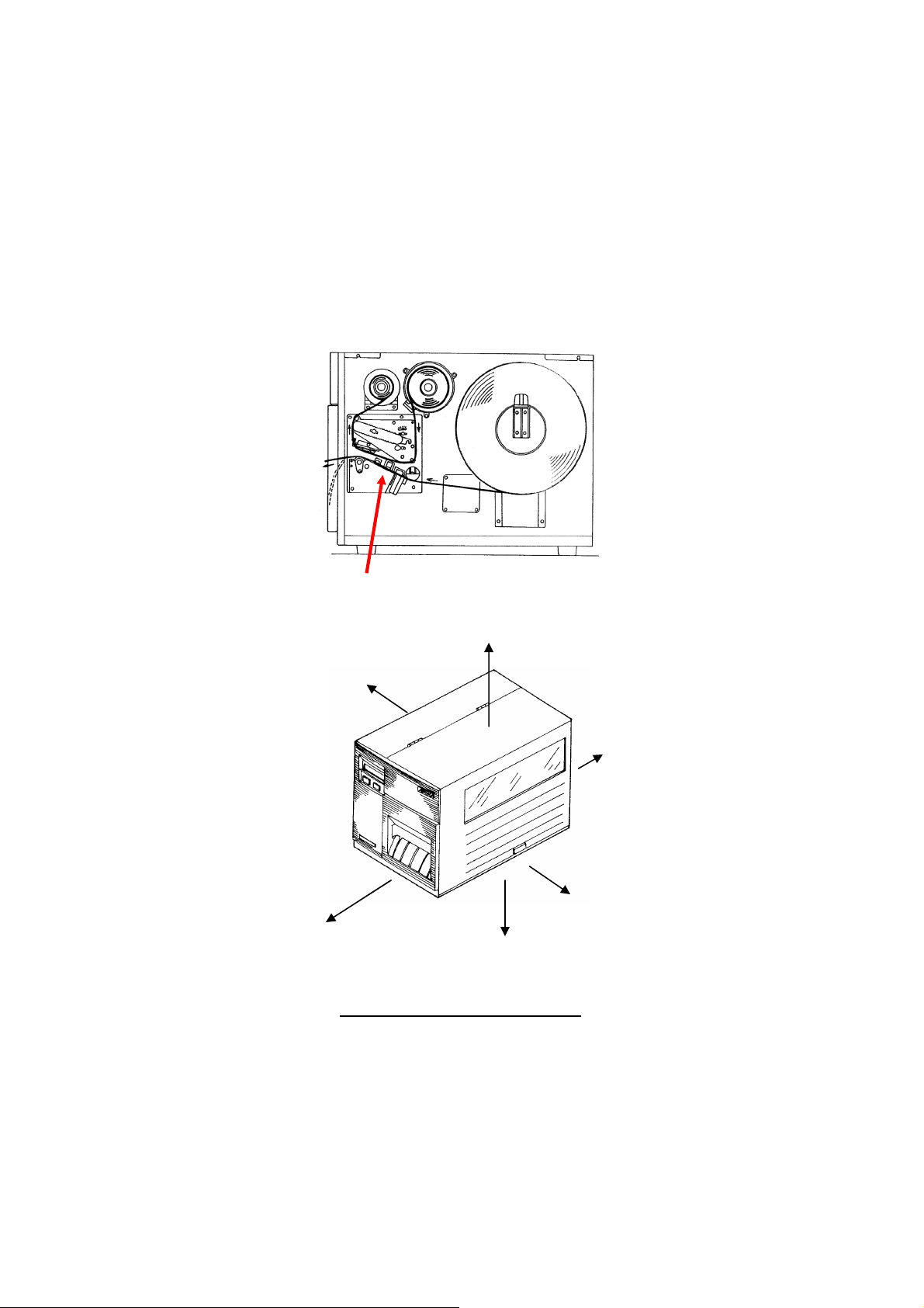
CAUTION
Please maintain the distance at least 20 cm (7.9 in) in an uncontrolled
environment from the antenna's surface when using the device.
See FCC OET Bulletin 56 "Hazards of radio frequency and
electromagnetic fields" and Bulletin 65 "Human exposure to radio
frequency electromagnetic fields."
This device shall not be co-located with any other transmitting antenna.
Antenna Position (Cover open view)
2cm
9cm
0cm (It leaves sufficiently)
18cm
12cm
6cm
The distance from outside the case
PN9001067 Rev B Page 1-1

CL408e/412e Quick Guide
Table of Contents
What You Get ................................................................................. 3
Controls and Indicators ................................................................... 4
Operator Panel ................................................................... 4
LED Indicators .................................................................... 4
Adjustments ........................................................................ 4
Keys ..................................................................................... 5
Rear Panel Connections ..................................................... 5
Initial Setup ..................................................................................... 6
Connecting the Printer ........................................................ 6
Printing a Test Label ........................................................... 7
Configuring the Printer ........................................................ 8
Computer Connections ....................................................... 8
CL408e/412e Software and Drivers ................................................. 10
Label Wizard SE ................................................................. 10
Windows Drivers ................................................................. 11
What to do if it will not print ........................................................... .... 11
CL408e/412e Specifications ............................................................ 15
Media and Supplies ......................................................................... 16
Options ............................................................................................ 16
Safety Considerations ...................................................................... 17
Safety Information ............................................................................ 18
This Quick Guide was prepared to get you up and running quickly. It will
enable you to get your new SATO CL408e/412e installed and printing
with a minimum of ef fort. H owev er, it is recomme nded th at yo u famili arize
yourself with the contents of the CL408e/412e Operator and Technical
Reference Manual for detailed descriptions so you will be able to
properly use the printer to its full potential.
PN9001067 Rev B Page 2
CL408e/412e Quic k Guide
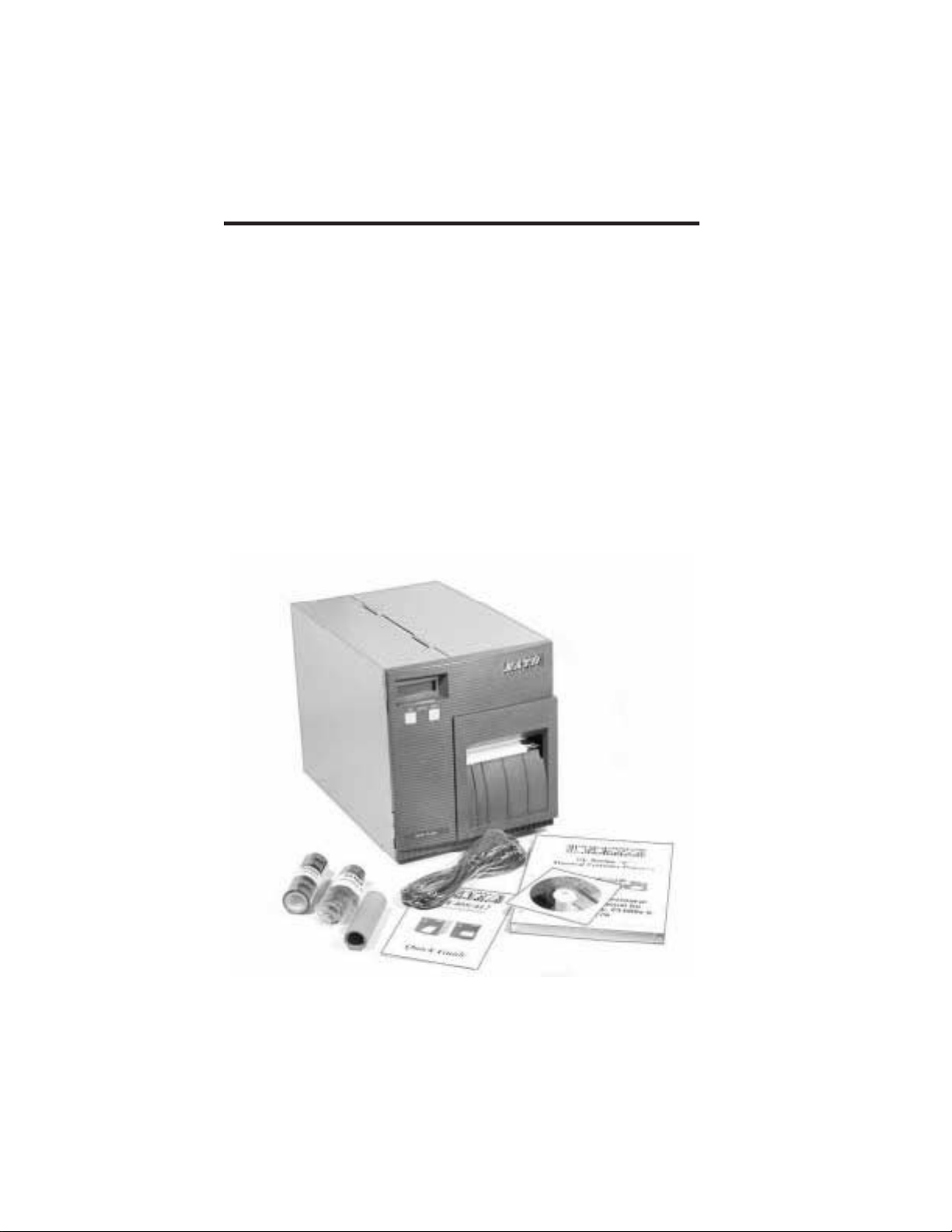
What YouGet
TheCL408e/412eThermal Transfer printer comespackedin aprotective
carton. Includedinthecartonarethefollowingitems:
CL408e/412ePrinter
•
Quick Guide
•
Operator andTechnical ReferenceManual
•
HeadCleaningSheet
•
SampleRibbonsandRibbonTake-Up Core
•
Power Cable
•
TestPrintoutLabels
•
Label WizardSE CD-ROM
•
AftertakingtheCL408e/412efromthecartonandremovingtheprotective
plastic cover, it is ready for installation.
PN 9001067 Rev B Page 3
Controls and Indicators
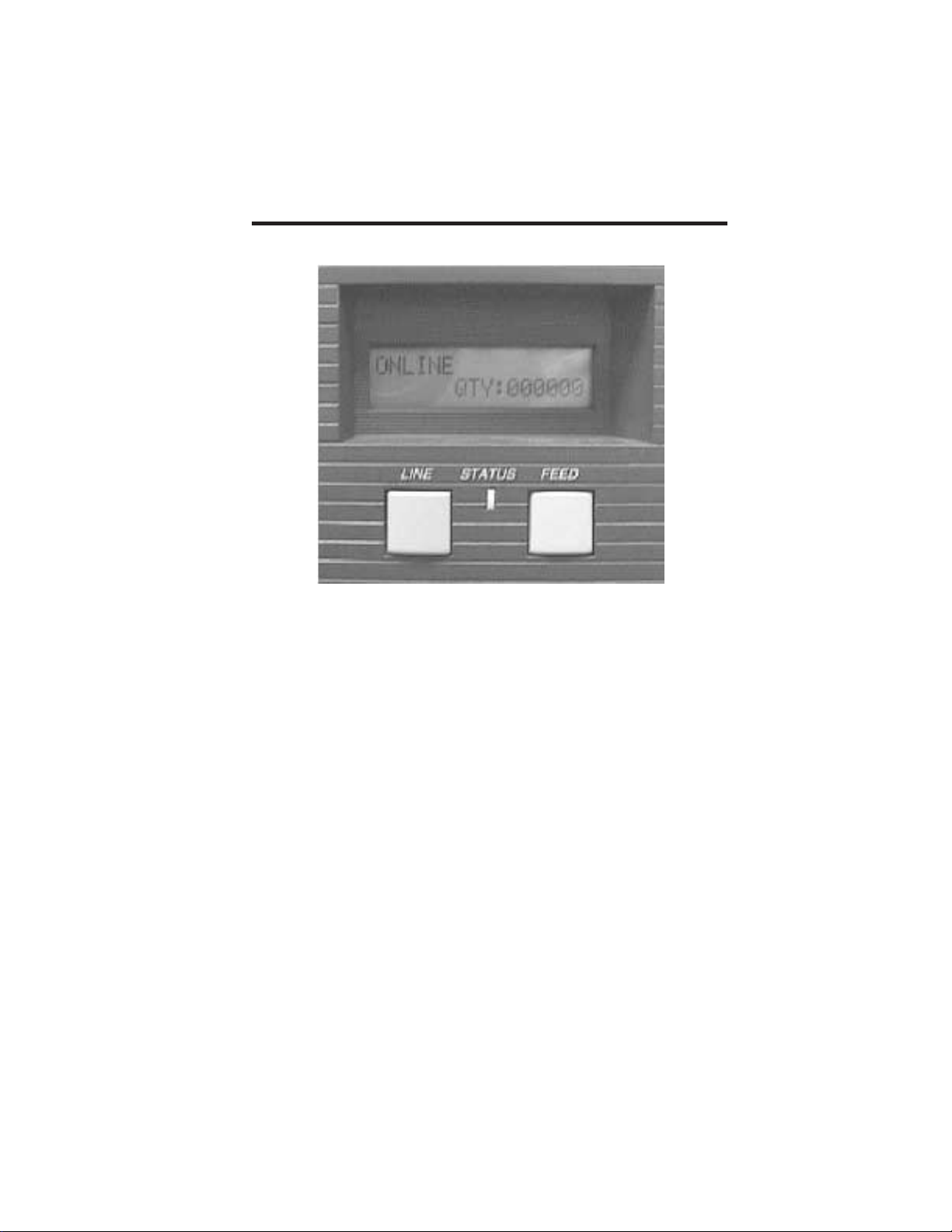
Operator Panel
LED Indicators
CL408e/412e Quic k Guide
Status: Dark whenOff Line
Greenwhenprinter is OnLine.
Redwhenan error conditionexists.
LCD Display: Illuminatedwhenpower is applied.
Adjustments(controls behindfrontpanel)
Print: Adjustsprintdarkness.
Offset: Adjustsamountof back/forwardfeedfordis-
pense/cut/tear-off position.
Pitch: Adjustshomepositionof thelabel +/- 3.75 mm. Affects
stoppositionof label, printpositionanddispense/cutpo-
sition.
DSW2-3: Setsprinter configuration
Page 4 PN 9001067 Rev B


CL408e/412e Quic k Guide
Initial Set-Up
Connectingthe Printer
1. Locatea suitablespotfor theprinter. It shouldbewithin 6 ft. of the
hostif usinganIEEE1284 Parallel interfaceorwithin35 ft. if usinga
HighSpeedRS232interface. For other types of Plug-In interface
cards, seetheOperatorandTechnical ReferenceManual. Makesure
thereis adequateroomaboveandtotherightof theprinter for thelabel accessdoortoswingopen.
2. PlugtheAC cable providedintotheback of theprinter andconnect
toa suitable 115VAC outlet.
3. Opentheprintheadandloadtheribbonusingtheribbonrouting
guidelocatedontheinsideof thetopcover. Besuretopositionthe
ribbonroll correctly ontheRibbonSupply Spindleandplacethe
sparetake-upcoreontheTake-Up Spindle. Tapethefreeendof the
ribbontothetake-upcoreso thatit will take-upwhenrotatingin a
counterclockwisedirection.
4. Placethelabel roll ontheLabel Supply Spindleandpushthegreen
Label Roll Retaineronthespindleuntil itpushes thelabel roll all the
way to theinsideof theprinter. Thelabels should comeoff thebottomof theroll (labels woundface-in ontheroll).
5. Routethelabels as indicatedby thelabel routingdiagramontheinsideof thetopcover. Thelabels should gounder theplastic guide,
throughtheLabel Sensor Assembly, under theprintheadandoutthe
frontof theprinter. PositiontheLabel EdgeGuidetowardtheinside
of theprinteruntil itbarely contacts theoutsideedgeof thelabels.
6. ClosethePrintHeadLatchandthenthesideaccess door last.
7. Selecttheproper label sensingmethodusingthefrontpanel DIP
switches. TheDIP switchfunctionchartis locatedontheinsideof
thefrontcover. Theprinter comes fromthefactory setforlabel gap
detection(DSW2-2, DSW3-3 bothOFF). NotethattheOFF position
for theDSW switchesis downandtheON positionup.
8. Apply power by placingthefrontpanel Powerswitchinthe“1" position.
9. ThePower andOn-LineLEDs should beilluminatedandONLINE
should bedisplayedontheLCD.
10. PresstheLINE key once. TheOnLineLED shouldgooutand
OFFLINE shouldbedisplayedontheLCD.
11. PresstheFEED key once. Theprinter shouldfeedoutonelabel and
stop.
Page 6 PN 9001067 Rev B


CL408e/412e Quick Guide
Safety Information
PN9001067 Rev B Page 18

CL408e/412e Quick Guide
Safety Information
PN9001067 Rev B Page 19

CL408e/412e Quick Guide
Safety Information
PN9001067 Rev B Page 20

CL408e/412e Quick Guide
Safety Information
PN9001067 Rev B Page 21
 Loading...