


INSTALLATION INSTRUCTIONS 8700, 12-8700, HC8700 & HC4-8700
SURFACE VERTICAL ROD EXIT DEVICE
U.S. Patent No. 268,003 Canadian Patent No. RD 1981
FOR ASSISTANCE, CONTACT SARGENT AT 800-727-5477 or www.sargentlock.com
Top case
 Top cover
Top rod
 Rod guide
Chassis
 Chassis
cover
Bottom rod
Bottom case
Standard 8700 Exit Shown
Copyright © 2009-2011, Sargent Manufacturing Company, an ASSA ABLOY Group company. All rights reserved. Reproduction in whole or in part without the express written permission of Sargent Manufacturing Company is prohibited.
CYLINDER DOGGING (16PREFIX)
For complete assembly information see
Instruction Sheet A6848
Must be installed with opening in plastic cam
Slide mounting rail insert with cylinder dogging (16prefix) into mounting rail
TO OPERATE:
•Depress push rail
•Insert key and turn counterclockwise to lockdown
(dog) push rail
 End cap bracket
 End cap
Push rail assembly
CAUTION: CHECK BEFORE STARTING DOOR PREP
Door should be fitted and hung.
Check box label for size of exit device, function, hand and design.
Surface of the door must |
THIS EXIT DEVICE IS HANDED |
|
|
|
|
be flush. Clear away any |
|
OUT |
raised projections to allow |
|
|
|
5 |
|
exit device to rest on flat |
|
|
surface of the door. |
Right hand |
Left hand |
|
||
AVAILABLE STOCK LENGTHS |
reverse bevel |
reverse bevel |
|
|
|
Length “E”: 32" door, no cut off required.
Can be cut to fit doors down to 24" wide.
Length “F”: 36" door, no cut off required.
Can be cut to fit doors down to 33" wide.
Length “J”: 42" door, no cut off required.
Can be cut to fit doors down to 37" wide.
Length “G”: 48" door, no cut off required.
Can be cut to fit doors down to 43" wide.
TOOLS REQUIRED
1. |
Measuring tape |
5. |
Hacksaw or any power cutter (to cut |
||
2. |
Power drill |
|
rail if necessary) |
|
|
3. |
Drill bits: #7, #16, #25, 3/32", 1/4", |
6. |
Screwdrivers: Phillips #2 and #3 |
|
|
|
11/32", 3/8", 25/64", and 3/4" |
7. |
Hex Wrenches: 3/16" and 3/8" |
|
|
4. |
Taps: #10-24, #12-24, 1/4"-20 and |
8. |
Level |
|
|
|
1 |
||||
|
7/16"-20 |
|
A6701L |
|
|
|
|
|
11-30-11 |
|
|
|
|
|
|
|
|
All 8700 series exit devices are handed except the 8710, which is field reversible.
The 8710 is shipped as LHR unless ordered as RHR.
TO CHANGE HAND OF 8710 EXIT DEVICE:
1.Remove both chassis pins and main slide.
2.Remove lift lever pin and lift lever.
3.Rotate chassis 180° and reposition lift lever and lift lever pin as shown.
4.Position main slide with large end of main slide at the bottom and retain with chassis pins.
Chassis
|
|
Lift lever pin |
|
|
|
|
|
Lift lever |
|
Lift lever |
|
Chassis pin |
|
|
|
|
|
||
Main slide |
Right Hand |
Left Hand |
Main Slide |
|
Large end |
||||
Large end |
Reverse |
Reverse |
||
|
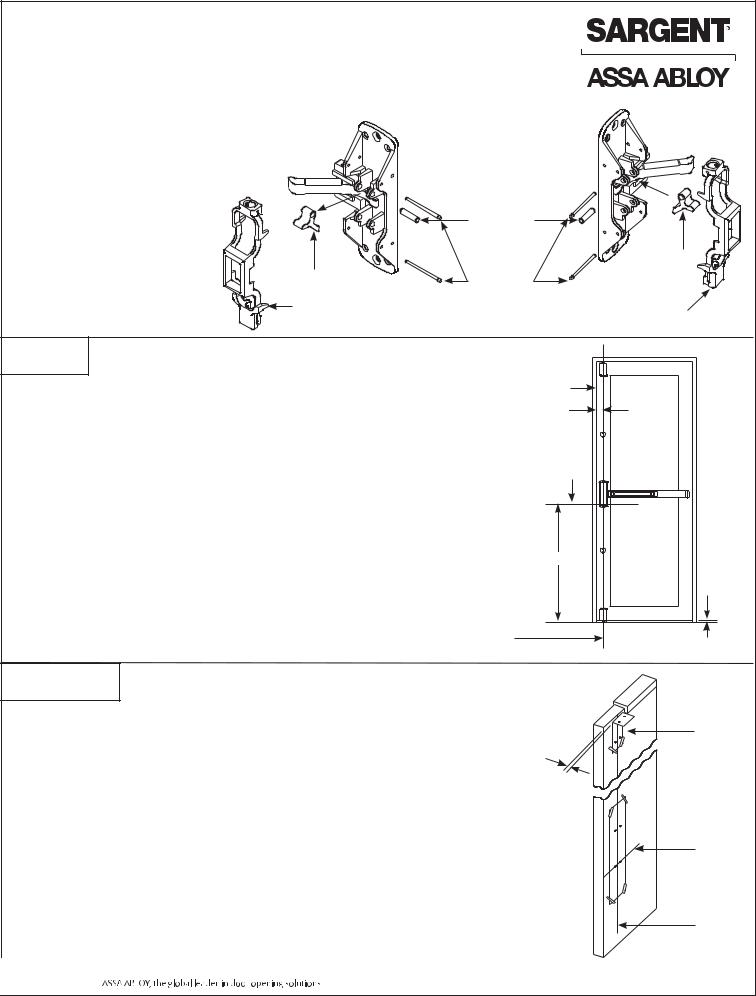
FIRST MARK VERTICAL AND HORIZONTAL REFERENCE LINES ON DOOR
WITH DOOR CLOSED:
1.Determine dimension “A” to locate vertical reference line. If door stile is 4-1/2" wide or wider, “A” is 2-3/4".
If door stile is less than 4-1/2", “A” is 1/2 the exposed
width of the door stile when the door is closed against the stop.
2.Standard rail centerline height is 41" above the finished floor. Horizontal reference line is 37-5/8" standard.
(Location of lower chassis mounting holes)
Door |
|
|
Stop |
|
|
“A” |
|
|
|
Inside |
|
Horizontal |
face of |
|
door |
||
reference |
||
|
||
line |
|
37-5/8"
Vertical reference line |
Finished floor |
(C chassis, top and bottom case) |
|
L |
|
SECOND PREPARE DOOR
WITH DOOR CLOSED:
1.Tape template for Chassis/Trim on inside of door, along vertical and horizontal reference lines.
2.Fold top case template and tape on inside of door along vertical reference lines.
3.Spot and drill all holes from inside of door.
4.Mortise pockets for outside trim, if required. See trim installation instructions supplied with trim for details.
NOTE: Any holes drilled from the outside need pilot holes drilled from the inside to ensure good alignment.
NOTE: For electrical trim applications, ensure access to a raceway from the trim to the electric hinge or armored door loop.
Top case Stop template thickness
Chassis/Trim 
Template Horizontal
reference
line
Tape (supplied) 
Vertical reference line
2 |
A6701L |
11-30-11 |
|
|
|
Copyright © 2009-2011, Sargent Manufacturing Company, an ASSA ABLOY Group company. All rights reserved. Reproduction in whole or in part without the express written permission of Sargent Manufacturing Company is prohibited.
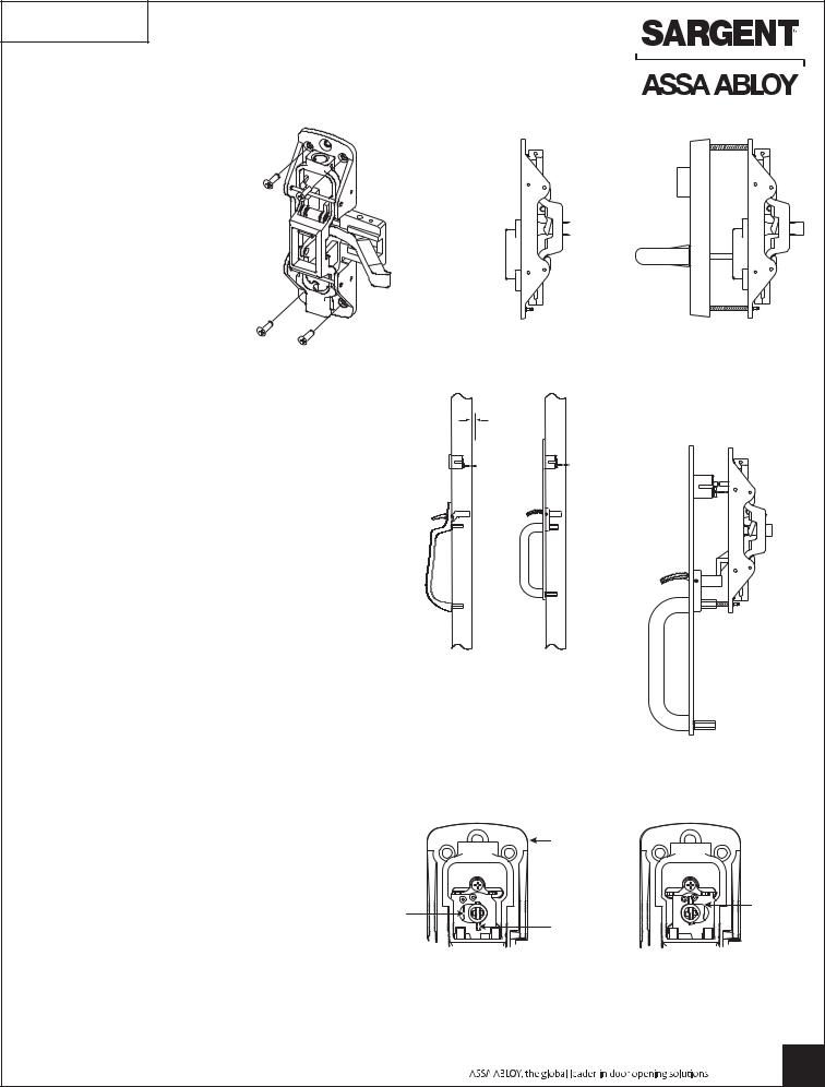
THIRD APPLY CENTER CHASSIS AND TRIM
700 SERIES ET TRIM:
1.Secure chassis to door with (4) #10 flat head screws using corner mounting holes.
NOTE: Electrical functions – see instruction sheet A6374 for wire connections.
2.Position ET trim on door, align spindle with bell housing.
3.Through-bolt chassis to ET trim with (2) 1/4-20 flat head screws.
 Chassis
Bell housing 
8706 OR 8713 BY
ETJ CONTROL SHOWN
NOTE: Thumb Trim is not available for HC8700 |
|
Series Exit Devices |
5/16" |
800 SERIES THUMB PIECE TRIM:
Determining rim cylinder tail length
FOR FLL, FLW, MAL, STS OR PTB TRIM:
1.Position trim on door (except STS).
2.Insert rim cylinder through trim plate (or cylinder collar for STS trim).
3. Mark cylinder tail at 5/16” beyond inside door surface.
4. Remove cylinder and trim from door and cut tail |
|
|
piece as marked. |
STS TRIM |
FLL TRIM |
|
SHOWN |
SHOWN |
APPLY CHASSIS AND TRIM:
1.Hold trim plate to door.
2.Insert cylinder and secure using supplied back plate.
3.Position cylinder hub with in the chassis to correct position for desired function (see drawings).
4.Position chassis on door, align cylinder tail with hub
and secure chassis to door with (4) #10 flat head |
|
Chassis |
|
screws using the corner mounting holes. |
|
||
|
|
||
5. Through-bolt chassis to trim with 1/4-20 flat head |
|
|
|
screws and to door with cup washer and 1/4-20 |
Cylinder |
||
flat head screw. |
|||
hub |
Hub pin |
||
NOTE: |
|||
|
down for |
||
|
|
||
STS, FLL, FLW and MAL thru-bolt to chassis |
|
62 function |
|
|
For 8762 long end of pin |
||
with (1) 1/4-20 flat head screw. |
|
||
PTB trim through-bolts to chassis with (2) 1/4-20 |
|
faces down. Cylinder turns |
|
|
180° in both directions. |
||
flat head screws. |
|
|
|
8762 OR 8763 BY FLW SHOWN
For 8763 long end of pin faces up. Cylinder turns 360° to the left or right.
Copyright © 2009-2011, Sargent Manufacturing Company, an ASSA ABLOY Group company. All rights reserved. Reproduction in whole or in part without the express written permission of Sargent Manufacturing Company is prohibited.
A6701L 3
11-30-11
 Loading...