


7000
7000
ELR Series
Multi-Point Lock
Installation Instructions
To view helpful video installation tips, scan the Microsoft®
Tags with your mobile phone. Download the free mobile
app at http://gettag.mobi.
A8147A
1/13
Copyright © 2013, Sargent Manufacturing Company, an ASSA ABLOY Group company.
All rights reserved. Reproduction in whole or in part without the express written
permission of Sargent Manufacturing Company is prohibited.
Table of Contents
1
Warning ...................................................................................2
2
General Description .................................................................3
3
Hardware Specifications .........................................................3
4
Electronics Specifications .......................................................3
5
Parts Breakdown For 7000 Exit Device ...................................6
6
Installation Instructions ..........................................................6
7
Wiring Diagrams ......................................................................9
8
Mechanical Operational Check .............................................10
Electrical Operational Check .................................................11
9
1
Warning
This device complies with Part 15 of the FCC Rules. Operation is subject to the following two conditions: (1) this
device may not cause harmful interference, and (2) this device must accept any interference received, including
interference that may cause undesired operation.
Note: This equipment has been tested and found to comply with the limits for a Class B digital device, pursuant to
Part 15 of the FCC Rules. These limits are designed to provide reasonable protection against harmful interference in
a residential installation.
This equipment generates, uses and can radiate radio frequency energy and if not installed and used in accordance
with the instructions, may cause harmful interference to radio communications. However, there is no guarantee that
the interference will not occur in a particular installation. If this equipment does cause harmful interference to radio
or television reception, which can be determined by turning the equipment off and on, the user is encouraged to try
to correct the interference by one or more of the following measures:
• Reorient or relocate the receiving antenna
• Increase the separation between the equipment and receiver
• Connect the equipment into an outlet on a circuit different from that to which the receiver is connected
• Consult the dealer or an experienced TV technician for help
This Class B digital apparatus complies with Canadian ICES-003.
Cet appareil numérique de la classe B est conforme avec la norme NMB-003 du Canada.
The term “IC:” before the radio certification number only signifies that Industry Canada technical specifications were
met. This Class B digital apparatus meets all requirements of the Canadian Interference Causing Equipment
Regulations. Operation is subject to the following two conditions: (1) this device may not cause harmful interference,
and (2) this device must accept any interference received, including interference that may cause undesired operation.
Cet appareillage numérique de la classe B répond à toutes les exigences de l’interférence canadienne causant des
règlements d’équipement. L’opération est sujette aux deux conditions suivantes: (1) ce dispositif peut ne pas causer
l’interférence nocive, et (2) ce dispositif doit accepter n’importe quelle interférence reçue, y compris l’interférence qui
peut causer l’opération peu désirée.
Changes or modifications to this unit not expressly approved by the party
responsible for compliance could void the user’s authority to operate the equipment.
Observe precautions for handling electrostatic sensitive devices.
!
Any retrofit or other field modification to a fire rated opening can potentially impact the fire rating of the
opening, and SARGENT Manufacturing makes no representations or warranties concerning what such impact may
be in any specific situation. When retrofitting any portion of an existing fire rated opening, or specifying and installing
Copyright © 2012, Sargent Manufacturing Company, an ASSA ABLOY Group company. All rights reserved.
Reproductions in whole or in part without express written permission of Sargent Manufacturing Company is prohibited.
1/31/13
a new fire-rated opening, please consult with a code specialist or local code official (Authority Having Jurisdiction) to
ensure compliance with all applicable codes and ratings.
2
A8147A • 800-810-WIRE (9473) • www.sargentlock.com
ELR 7000 Series Multi Point Lock
2
General Description
The SARGENT stand alone ELR 7000 series multi point lock is designed to automatically retract the
rods, concealed within the door.
1. Functions
The 7000 ELR can be configured to work in either of two modes:
POWER MODE (see Section II: POWER MODE)
The device is not energized when locked. When electrified, the device and remain in the retracted posi-
tion until power is removed. Power is typically applied through a relay triggered by an access control
device.
TIMER MODE (see Section III: TIMER MODE)
The device is always energized and retraction is triggered by a momentary or maintain switch.
In TIMER MODE:
When the timer circuit is closed using a momentary switch, the device retracts, remains retracted for a set
duration, and releases. The duration of the retraction is set through an onboard timer setting.
When the timer circuit is closed using a maintain switch, the device retracts. The device releases when
the contact is opened.
2. Important
Caution: Disconnect all input power before servicing.
Installer must be a trained and experienced service person.
Wiring must comply with applicable local electrical codes, ordinances and regulations.
3. Installation Notes
Earth Ground: Required for electrostatic discharge (ESD) protection, unless already grounded through
the metal door and frame.
3
Hardware Specifications
• Certified ANSI/BHMA A156.3 Grade 1
• Fire rated devices available
• UL and CUL listed for use on Fire Doors
• Multi point lock furnished for 1-3/4” doors
• Wire from EAC Panel to door must be shielded
with a drain terminated at EAC Panel controller
7000 Series Multi Point Lock
• Cylinder override available for 7000 CVR with
106 Series Auxiliary Control
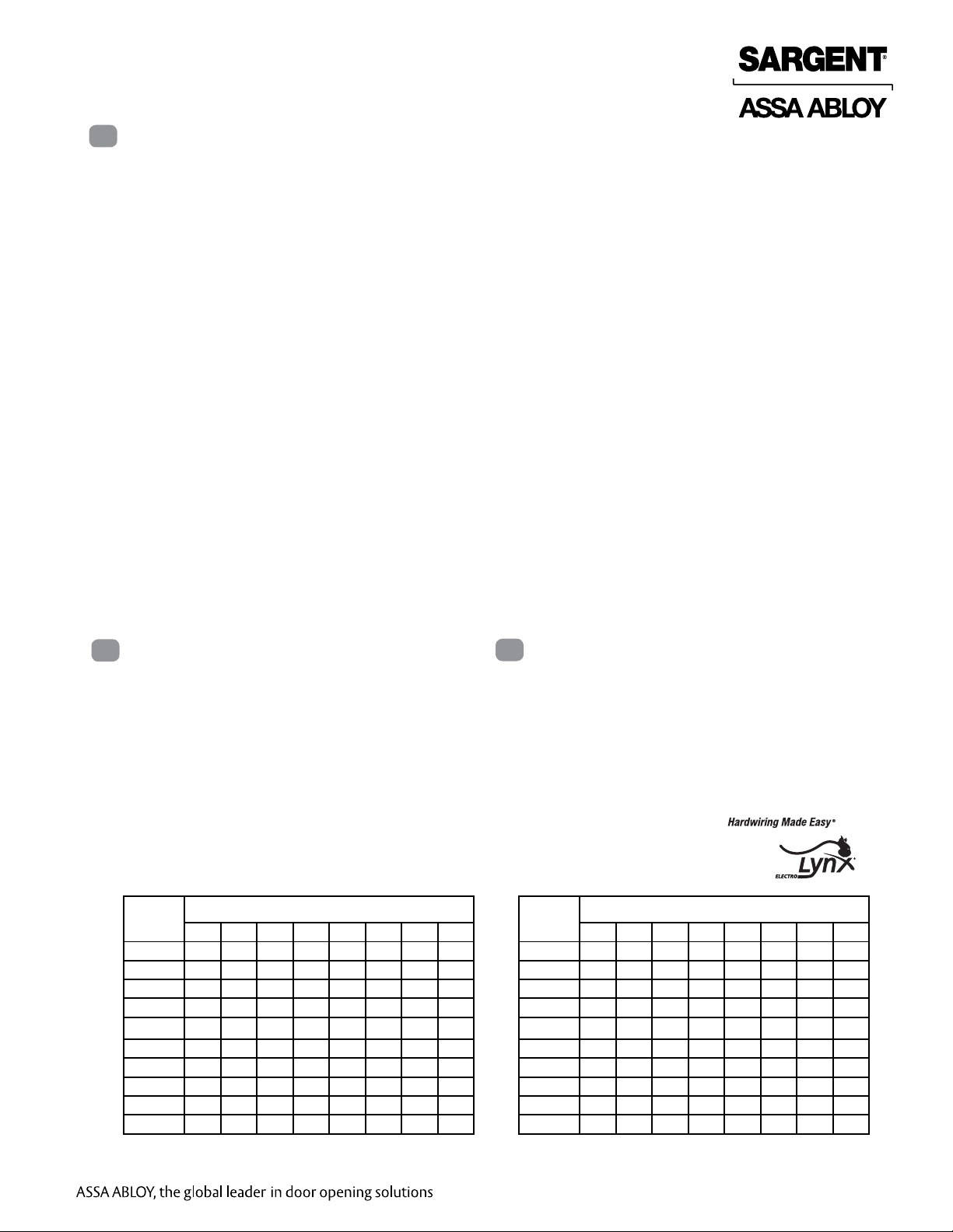
Total
One-Way
Length of
Wire Run (ft)
1/4A 1/2A 3/4A 1A 1-1/4A 1-1/2A 2A 3A
100 20 18 16 14 14 12 12 10
150 18 16 14 12 12 12 10 —
200 16 14 12 12 10 10 — —
250 16 14 12 10 10 10 — —
300 16 12 12 10 10 — — —
400 14 12 10 — — — — —
500 14 10 10 — — — — —
750 12 10 — — — — — —
1,000 10 — — — — — — —
1,500 10 — — — — — — —
Load Current @ 12VDC
4
Wire Gauge Charts
Total
One-Way
Length of
Wire Run (ft)
Electronic Specifications
12VDC System
• 12VDC ELR Draw = 850mA
24VDC System
• 24VDC ELR Draw = 700mA
Load Current @ 24VDC
1/4A 1/2A 3/4A 1A 1-1/4A 1-1/2A 2A 3A
100 24 20 18 18 16 16 14 12
150 22 18 16 16 14 14 12 10
200 20 18 16 14 14 12 12 10
250 18 16 14 14 12 12 12 10
300 18 16 14 12 12 12 10 —
400 18 14 12 12 10 10 — —
500 16 14 12 10 10 — — —
750 14 12 10 10 — — — —
1,000 14 10 10 — — — — —
1,500 12 10 — — — — — —
Copyright © 2013, Sargent Manufacturing Company, an ASSA ABLOY Group company. All rights reserved.
Reproductions in whole or in part without express written permission of Sargent Manufacturing Company is prohibited.
3
A8147A • 800-810-WIRE (9473) • www.sargentlock.com
1/31/13
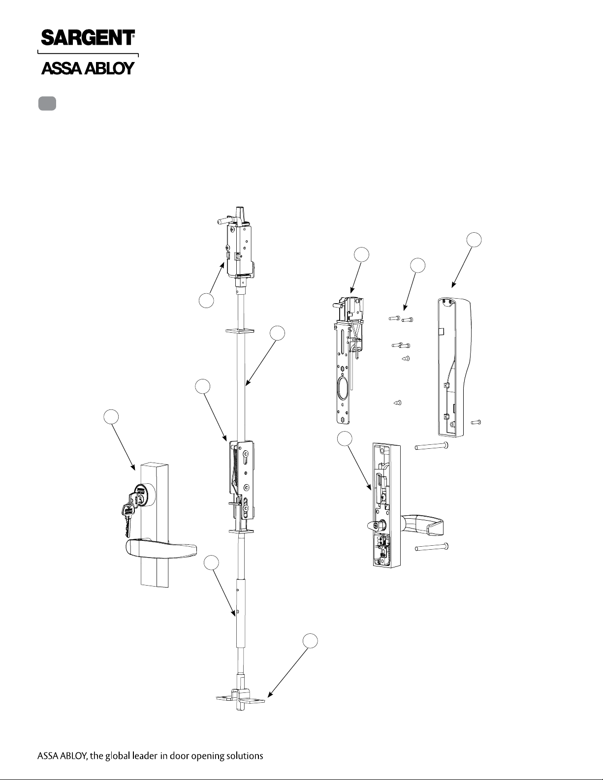
5
Parts Breakdown for ELR 7000 Series
Tools Required
• Phillips screw driver (standard size)
• Slotted screw driver (standard size)
• Drill
• #8-32 tap & tap drill
(for metal door applications)
6
ELR 7000 Series Multi Point Lock
10
11
12
5
3
2
1
7
Copyright © 2013, Sargent Manufacturing Company, an ASSA ABLOY Group company. All rights reserved.
Reproductions in whole or in part without express written permission of Sargent Manufacturing Company is prohibited.
1/31/13
4
4
A8147A • 800-810-WIRE (9473) • www.sargentlock.com

ELR 7000 Series Multi Point Lock
Parts Breakdown Continued...
ITEM PART # Description Req.
1 MP-7XX-2 WD/MD/AD Inside Trim Assembly 1
2 7XX-2 Outside Trim Assembly 1
3A 94-2411 MD/AD Inner Chassis Assembly
94-2412 MD/AD Inner Chassis Assembly, Fire (12-)
94-2414 MD/AD Monitoring Inner Chassis, Fire (53-/12-53-)
3B MD69IT WD Inner Chassis Assembly 1
WD69IT WD Monitoring Inner Case (53-)
4 68-0888 Bottom Case 1
5A 68-7062 MD/AD Top Rod and Bolt Assembly 1
5B 68-5829 WD Top Rod and Bolt Assembly 1
6 68-5374 Top Case Assembly 1
7 96-2085 Bottom Rod and Bolt Assembly 1
8 97-0825 Standard Plate (Rectangular) (Not shown) 2
97-0826 Sculpted Plate (Optional) (Not shown)
9 68-1264 WD Top Case Bracket (Not shown) 1
10 97-4056 Cover Assembly 1
10B 650 Top Strike Pack (Not shown) 1
606 Bottom Strike Pack, Fire (12-)(HC)(WS) (Not shown)
652 Top and Bottom Strike Pack, STD (Not shown)
11 52-4697 ELR Assembly 1
11A 94-2415 MD/AD Screw Pack (Not shown) 1
11B 94-2431 WD Screw Pack (Not shown) 1
12 52-5236 Screw Pack (Not shown) 1
12A 52-4723 MD/AD Mounting Hardware 1
12B 52-4724 WD Mounting Hardware 1
How to Specify ET Trim
Specify: 7 for ET Series Trim, Function, Suffix, Lever, Finish and handing (e.g., 713-2 ETL
x 26D x RH).
Note: Suffix requirements are based on type of device to be used:
• -2 suffix is required for all 7000, WD, MD and AD.
• MP- prefix is for inside 7000 trim.
5
A8147A • 800-810-WIRE (9473) • www.sargentlock.com
Copyright © 2013, Sargent Manufacturing Company, an ASSA ABLOY Group company. All rights reserved.
Reproductions in whole or in part without express written permission of Sargent Manufacturing Company is prohibited.
1/31/13
ELR 7000 Series Multi Point Lock
6
Installation Instructions
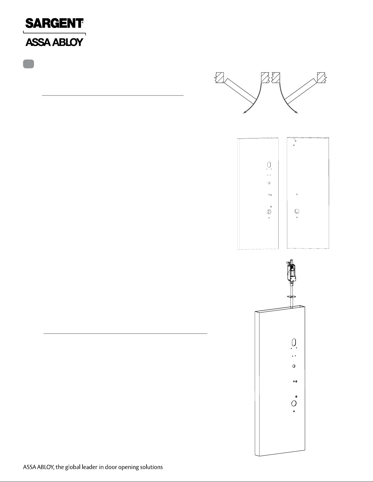
1 Door Preparation
A. Verify Hand and Bevel of Door
• Check hand of door. The Multi-Point lock may be handed.
• Door should be fitted and hung.
• Verify box label for size of the Multi-Point lock, function and
hand.
B. Door Preparation
Prepare door according to appropriate template. If necessary,
refer to www.intelligentopenings.com.
• Metal door (MD/AD): A7860
- Template: 4582
• Wood door (WD): A7971
- Template: 4624
Left Hand
Reverse
LHR
Inside
Outside
Fig. 1A
Right Hand
Reverse
RHR
2 Rod and Inner Case Installation
1. Refer to instruction sheet A7860 for rod and inner
case installation on metal doors.
2. Refer to instruction sheet A7971 for rod and inner
case installation on wood doors.
Fig. 1B Metal Shown
Copyright © 2013, Sargent Manufacturing Company, an ASSA ABLOY Group company. All rights reserved.
Reproductions in whole or in part without express written permission of Sargent Manufacturing Company is prohibited.
1/31/13
6
Fig. 2
A8147A • 800-810-WIRE (9473) • www.sargentlock.com
 Loading...