


Degree™ Key System
Technical Manual
Copyright © 2013-2014, Sargent Manufacturing Company, an ASSA ABLOY Group company. All rights reserved. Reproduction in whole or in part without the express written permission of Sargent Manufacturing Company is prohibited.

Table of Contents
Degree™ Key System Technical Manual
Table of Contents
The Degree™ Advantage |
1 |
DG1 Key Cuts |
2 |
DG2 & DG3 Key Cuts |
3 |
Pinning Formula . . . . . . . . . . . . . . . . . . . . . . . . . . . . . . . . . . . . . . . . . . . . . . . . 4 |
|
Construction Master Keying (21-Option) |
5 |
Visual Key Control Tamper Proof Packaging |
6 |
Degree Pin Kits |
7 |
Cylinder Parts: DG1-34 Rim/ DG1-40 Series Mortise |
8 |
Cylinder Parts: DG2-34 Rim/ DG2-40 Series Mortise |
9 |
Cylinder Parts: DG3-34 Rim/ DG3-40 Series Mortise |
10 |
Cylinder Parts: DG1-LFIC Cores |
11 |
Cylinder Parts: DG2-LFIC Cores |
12 |
Cylinder Parts: DG3-LFIC Cores |
13 |
Cylinder Parts: DG1 Bored, Auxiliary, & Integralock |
14 |
Cylinder Parts: DG2 Bored, Auxiliary, & Integralock |
15 |
Cylinder Parts: DG3 Bored, Auxiliary, & Integralock |
16 |
Groupcompany. All rights reserved. |
Sargent Manufacturing Company is prohibited. |
Manufacturing Company, an ASSA ABLOY |
withoutthe express written permission of |
Copyright © 2013-2014, Sargent |
Reproduction in whole or in part |
On The Cover
90726:E 4/30/14
DG1-41 Mortise cylinder, Degree Key and Degree DG1-6300 series core
1-800-727-5477 • www.sargentlock.com
The Degree™ Advantage
Degree™ Key System Technical Manual
The Degree Key System
The patented Degree system from SARGENT provides the right level of security for each opening in your facility. Three levels of ANSI/ BHMA Grade 1 protection, from patented keyway to UL437 certified, secures every opening. A common key for all three levels of security enhances key control and simplifies administrative procedures. Key blanks are controlled through authorized distribution and geographical protection is available. Available for mortise, rim, component and Large Format Interchangeable Core (LFIC) cylinders, SARGENT offers the
right Degree of protection for every door in your facility.
Benefits
•Patent protection from unauthorized key duplication through 2027
•New keyway family protects system integrity from legacy systems
•Keys are significantly stronger than competitive systems
•User-friendly design with minimal components provides easy field service
•Availability in all existing SARGENT cylinder types provides cost-effective upgrade for SARGENT facilities
•Bump resistance for added protection
Degree Level 1 (DG1) features a utility patented keyway and provides protection against bumping for mortise, rim and component fixed cylinders. These cylinders easily retrofit into existing hardware and are appropriate for most applications. The keys for DG1 can only open DG1 cylinders.
Degree Level 2 (DG2) builds on the utility patented keyway of DG1 and adds patented side bar locking with unique angled bottom pins that provide end users with geographical exclusivity. Cylinders provide protection against bumping and picking. Because of its superior key control and patent protection until 2027, DG2 products are recommended for use in conjunction with DG3 for new installations or when retrofitting systems, including large format interchangeable core systems.
Degree Level 3 (DG3) combines the utility patented keyway and side bar locking with unique angled bottom pins that provide end users with geographical exclusivity, and adds certification to UL437. They are classified as high security because of their superior resistance to physicalattackandprotectionagainstunauthorized key duplication. Because of its superior key control, patent protection until 2027, and physical strength, we recommend DG3 products for new high-security installations or when retrofitting systems, including large format interchangeable core systems. SARGENT also offers anti-vandal and high security locksets that complement DG3 cylinders for those openings most vulnerable to attack.
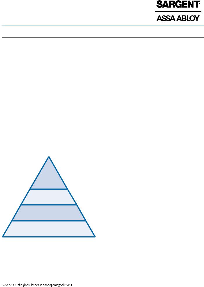
SARGENT Cylinder & Key Control Products
High |
High Security: UL437 Drill & Pick Resistant Systems offer protection |
|
against physical attacks. Includes Degree DG3, UL-Signature |
||
Security |
||
and UL-Keso. |
||
|
Security
Patented Keyway
Open Conventional
Security: Protection against picking. Includes Degree DG2, Signature and Keso.
Patented Keyway: Keys are protected against unauthorized duplication. Includes Degree DG1 and XC.
Open Conventional: Legacy systems whose patents have run out and are not protected.
Groupcompany. All rights reserved. |
Sargent Manufacturing Company is prohibited. |
Manufacturing Company, an ASSA ABLOY |
withoutthe express written permission of |
Copyright © 2013-2014, Sargent |
Reproduction in whole or in part |
1-800-727-5477 • www.sargentlock.com |
1 |
90726:E 4/30/14

DG1 Key Cuts
Groupcompany. All rights reserved. |
Sargent Manufacturing Company is prohibited. |
Manufacturing Company, an ASSA ABLOY |
withoutthe express written permission of |
Copyright © 2013-2014, Sargent |
Reproduction in whole or in part |
90726:E 4/30/14
Degree™ Key System Technical Manual
DG1 cuts from Bow to Tip
.170±.001TYP. |
|
|
.2440±.0025 |
|
.271±.0015 (1) |
|
90° |
|
|
.241±.0015 (2) |
|
|
TYP. |
|
|
|
.211±.0015 (3) |
|
|
.181±.0015 (4) |
|
|
.151±.0015 (5) |
|
(.307) |
.121±.002 (6) |
|
|
|
|
|
.054±.001 |
1 2 3 4 5 6 |
REFERENCE LINE BOTTOM OF KEY |
|
Bottom Pins (BP) for DG1cylinders
|
Size # |
|
Part No. |
|
Length |
|
|
1 |
|
DG-0021 |
|
.231 |
|
|
|
|
|
|||
|
2 |
|
DG-0022 |
|
.261 |
|
|
3 |
|
DG-0023 |
|
.291 |
|
|
4 |
|
DG-0024 |
|
.321 |
|
|
5 |
|
DG-0025 |
|
.351 |
|
|
6 |
|
DG-0026 |
|
.381 |
|
Driver Pins (DP)
for DG1standard cylinders
Size # |
Part No. |
Length |
|
|
|
1 |
DG-0051 |
.030 |
2 |
DG-0052 |
.060 |
3 |
DG-0053 |
.090 |
4 |
DG-0054 |
.120 |
5 |
DG-0055 |
.150 |
6 |
DG-0246 |
.180 |
7 |
DG-0247 |
.210 |
8 |
DG-0248 |
.240 |
9 |
DG-0249 |
.270 |
Master Wafers (MW) for all DGseries
|
Size # |
|
Part No. |
|
Length |
|
|
1 |
|
DG-0051 |
|
.030 |
|
|
|
|
|
|||
|
2 |
|
DG-0052 |
|
.060 |
|
|
3 |
|
DG-0053 |
|
.090 |
|
|
4 |
|
DG-0054 |
|
.120 |
|
|
5 |
|
DG-0055 |
|
.150 |
|
Driver Pins (DP)
for DG2- & DG3cylinders and all DGLarge Format Interchangeable Cores
Size # |
Part No. |
Length |
1 |
DG-0051 |
.030 |
2 |
DG-0052 |
.060 |
3 |
DG-0053 |
.090 |
4 |
DG-0054 |
.120 |
5 |
DG-0045 |
.150 |
6 |
DG-0044 |
.180 |
7 |
DG-0043 |
.210 |
8 |
DG-0042 |
.240 |
9 |
DG-0041 |
.270 |
2 |
1-800-727-5477 • www.sargentlock.com |
Control Drivers (CD) for all DGLarge Format Interchangeable Cores (3 & 4 Chambers)
|
|
|
|
|
|
|
|
Size # |
|
Part No. |
|
Length |
|
|
|
|||||
|
1 |
|
DG-0051 |
|
.030 |
|
|
2 |
|
DG-0052 |
|
.060 |
|
|
3 |
|
DG-0053 |
|
.090 |
|
|
4 |
|
DG-0054 |
|
.120 |
|
|
5 |
|
DG-0055 |
|
.150 |
|
|
6 |
|
n/a |
|
|
|
|
7 |
|
DG-0247 |
|
.210 |
|
|
8 |
|
DG-0248 |
|
.240 |
|
|
9 |
|
DG-0249 |
|
.270 |
|
|
10 |
|
DG-0250 |
|
.300 |
|
|
11 |
|
DG-0251 |
|
.330 |
|
|
Driver Pins (DP) for Bump |
|||||
|
Resistance (DG1 Only) |
|
||||
|
|
|
|
|
|
|
|
Size # |
|
Part No. |
|
Length |
|
|
1 |
|
DG-0036 |
|
.120 |
|
|
2 |
|
DG-0035 |
|
.150 |
|
|
3 |
|
DG-0034 |
|
.180 |
|
|
5 |
|
DG-0033 |
|
.210 |
|
|
6 |
|
DG-0032 |
|
.240 |
|
|
7 |
|
DG-0031 |
|
.270 |
|

DG2 & DG3 Key Cuts
Degree™ Key System Technical Manual
DG2 DG3 cuts |
R |
R C |
L |
L C |
|
||||
|
20° |
|
|
20° |
|
.170 ±.001TYP. |
|
|
|
|
.2440±.0025 |
|
|
|
(.307)
1 2 3 4 5 6
Dimensions shown are to theoretical intersection
Bottom Pins (BP)
for DG2- & DG3cylinders
First 5 positions (Angled Pins)
Size # |
Angle |
Part No. |
Length |
|
L |
DG-0111 |
|
1 |
C |
DG-0121 |
.231 |
|
|
|
|
|
R |
DG-0131 |
|
|
L |
DG-0112 |
|
2 |
C |
DG-0122 |
.261 |
|
R |
DG-0132 |
|
|
L |
DG-0113 |
|
3 |
C |
DG-0123 |
.291 |
|
R |
DG-0133 |
|
|
L |
DG-0114 |
|
4 |
C |
DG-0124 |
.321 |
|
R |
DG-0134 |
|
|
L |
DG-0115 |
|
5 |
C |
DG-0125 |
.351 |
|
R |
DG-0135 |
|
|
L |
DG-0116 |
|
6 |
C |
DG-0126 |
.381 |
|
R |
DG-0136 |
|
6th (last) position
Size # |
Part No. |
Length |
|
|
|
|
|
1 |
|
DG-0021 |
.231 |
2 |
|
DG-0022 |
.261 |
|
|
|
|
3 |
|
DG-0023 |
.291 |
4 |
|
DG-0024 |
.321 |
5 |
|
DG-0025 |
.351 |
6 |
|
DG-0026 |
.381 |
Control Drivers (CD) for all DGLarge Format Interchangeable Cores (3 & 4 Chambers)
Size # |
Part No. |
Length |
1 |
DG-0051 |
.030 |
2 |
DG-0052 |
.060 |
3 |
DG-0053 |
.090 |
4 |
DG-0054 |
.120 |
5 |
DG-0055 |
.150 |
6 |
n/a |
|
7 |
DG-0247 |
.210 |
8 |
DG-0248 |
.240 |
9 |
DG-0249 |
.270 |
10 |
DG-0250 |
.300 |
11 |
DG-0251 |
.330 |
|
.259±.001 (1) |
|
86° |
.229±.001 |
(2) |
.199±.001 (3) |
||
TYP. |
.169±.001 (4) |
|
|
||
.139±.001 (5)
.109±.001 (6)
REFERENCE LINE BOTTOM OF KEY
Master Wafers (MW) for all DGseries
Size # |
Part No. |
Length |
1 |
DG-0051 |
.030 |
2 |
DG-0052 |
.060 |
3 |
DG-0053 |
.090 |
4 |
DG-0054 |
.120 |
5 |
DG-0055 |
.150 |
Driver Pins (DP)
for DG2- & DG3cylinders and all DGLarge Format Interchangeable Cores
Size # |
Part No. |
Length |
|
|
|
1 |
DG-0051 |
.030 |
2 |
DG-0052 |
.060 |
3 |
DG-0053 |
.090 |
4 |
DG-0054 |
.120 |
5 |
DG-0045 |
.150 |
6 |
DG-0044 |
.180 |
7 |
DG-0043 |
.210 |
8 |
DG-0042 |
.240 |
9 |
DG-0041 |
.270 |
1-800-727-5477 • www.sargentlock.com |
3 |
Groupcompany. All rights reserved. |
Sargent Manufacturing Company is prohibited. |
Manufacturing Company, an ASSA ABLOY |
withoutthe express written permission of |
Copyright © 2013-2014, Sargent |
Reproduction in whole or in part |
90726:E 4/30/14

Pinning Formula
Degree™ Key System Technical Manual
Fixed Core Cylinders - All 6 Chambers |
Large Format Interchangeable Core - |
Large Format Interchangeable Cores |
Control Chambers |
(Chambers 1-2-5-6) |
(Chambers 3 and 4 Only) |
Groupcompany. All rights reserved. |
Sargent Manufacturing Company is prohibited. |
Manufacturing Company, an ASSA ABLOY |
withoutthe express written permission of |
Copyright © 2013-2014, Sargent |
Reproduction in whole or in part |
Non-LFIC
Driver Pin (DP) |
|
Example |
|
|
|
|
|
|
|
Master Key |
1 |
2 |
3 |
4 |
6 |
4 |
|
10 MINUS |
|
|||||||
|
Change Key |
3 |
4 |
5 |
2 |
2 |
2 |
|
Plug Total |
|
|||||||
|
|
|
|
|
|
|
|
|
|
|
|
|
|
|
|
|
|
|
|
Driver Pin (DP) |
7 |
6 |
5 |
6 |
4 |
6 |
Master Wafer |
|
|||||||
(MW) Pin = |
|
Master Wafer (MW) |
2 |
2 |
2 |
2 |
4 |
2 |
Deepest Minus |
|
Bottom Pin (BP) |
1 |
2 |
3 |
2 |
2 |
2 |
Shallowest |
|
|
|
|
|
|
|
|
|
|
|
|
|
|
|
|
|
Operating Cut |
|
|
|
|
|
|
|
|
|
Plug Total (MW + BP) |
|
|
|
|
|
|
|
Bottom Pin = |
|
|
|
|
|
|
||
|
|
|
|
|
|
|
|
|
Shallowest |
|
|
|
|
|
|
|
|
Operating Cut |
|
|
|
|
|
|
|
|
Instructions
Bottom Pin = shallowest operating cut
Master Wafer (if required) = Deepest minus shallowest operating cut
(Plug Total = Bottom Pin + Master Wafer) Driver Pin = 10 MINUS Plug Total
LFIC
Driver Pin (DP) |
|
Example |
|
|
|
|
|
|
|
13 MINUS Plug |
|
|
|
|
|
|
|
||
|
Control Key |
1 |
5 |
5 |
4 |
3 |
2 |
||
Total and |
|
||||||||
Control Driver |
|
Master Key |
1 |
5 |
2 |
6 |
3 |
2 |
|
|
|
|
Change Key |
3 |
1 |
4 |
3 |
1 |
5 |
|
|
|
|||||||
|
|
|
|
|
|
|
|
|
|
|
|
|
|
|
|
|
|
|
|
Control |
|
|
|
|
|
|
|
|
|
|
Driver Pin (DP) |
7 |
5 |
2 |
3 |
7 |
5 |
||
Driver (CD) = |
|
||||||||
Control Cut PLUS 6 |
|
Control Driver (CD) |
x |
x |
7 |
4 |
x |
x |
|
MINUS Plug Total |
|
Master Wafer (MW) |
2 |
4 |
2 |
3 |
2 |
3 |
|
|
|
|
|
|
|
|
|
|
|
|
|
|
Bottom Pin (BP) |
1 |
1 |
2 |
3 |
1 |
2 |
|
|
|
|||||||
|
|
|
|
|
|
|
|
|
|
|
|
|
|
|
|
|
|
|
|
Master Wafer |
|
|
|
|
|
|
|
|
|
(MW) Pin = |
|
|
|
|
|
|
|
|
|
Deepest MINUS |
|
|
|
|
|
|
|
|
|
Shallowest |
|
|
|
|
|
|
|
|
|
Operating Cut |
|
|
|
|
|
|
|
|
|
|
|
Plug Total (MW +BP) |
|
|
|
|
|
|
|
Bottom Pin = |
|
|
|
|
|
|
|||
|
|
|
|
|
|
|
|
||
Shallowest |
|
|
|
|
|
|
|
|
|
Operating Cut |
|
|
|
|
|
|
|
|
|
Instructions
Bottom Pin = shallowest operating cut
Master Wafer (if required) = Deepest minus shallowest operating cut
(Plug Total = Bottom Pin + Master Wafer)
Control Driver (CD) = Control cut PLUS 6 MINUS Plug Total
Driver Pin = 13 MINUS Plug Total and CD# = DP
90726:E 4/30/14
4 |
1-800-727-5477 • www.sargentlock.com |
 Loading...