

Page 1

BT-
Beacon
Exit Device
Installation Instructions
A7974C
02/13
Copyright © 2013, Sargent Manufacturing Company, an ASSA ABLOY Group company.
All rights reserved. Reproduction in whole or in part without the express written permission
of Sargent Manufacturing Company is prohibited.
Page 2
Beacon Exit Device
Installation and Wiring Instructions
Table of Contents
Warning ...................................................................................2
Section I - Overview ................................................................3
Section II - Installation Instructions .......................................6
Section III - Beacon Wiring Examples ..................................10
Section IV - Alarm Mode Operation ......................................15
Section V - Test Mode Operation ..........................................15
Section VI - BEACON Modes of Operation ............................16
Trouble Conditions & Corrective Actions .............................17
Changes or modifications to this unit not expressly approved by ASSA ABLOY Inc.could void the user’s
Warning
This device complies with Part 15 of the FCC Rules. Operation is subject to the following two conditions: (1) this
device may not cause harmful interference, and (2) this device must accept any interference received, including
interference that may cause undesired operation.
Note: This equipment has been tested and found to comply with the limits for a Class B digital device, pursuant to
Part 15 of the FCC Rules. These limits are designed to provide reasonable protection against harmful interference in
a residential installation.
This equipment generates, uses and can radiate radio frequency energy and if not installed and used in accordance
with the instructions, may cause harmful interference to radio communications. However, there is no guarantee that
the interference will not occur in a particular installation. If this equipment does cause harmful interference to radio or
television reception, which can be determined by turning the equipment off and on, the user is encouraged to try to
correct the interference by one or more of the following measures:
• Reorient or relocate the receiving antenna
• Increase the separation between the equipment and receiver
• Connect the equipment into an outlet on a circuit different from that to which the receiver is connected
• Consult the dealer or an experienced TV technician for help
This Class B digital apparatus complies with Canadian ICES-003.
Cet appareil numérique de la classe B est conforme avec la norme NMB-003 du Canada.
authority to operate the equipment.
Copyright © 2013 Sargent Manufacturing Company, an ASSA ABLOY Group company. All rights reserved.
Reproductions in whole or in part without express written permission of Sargent Manufacturing Company is prohibited.
FOR INSTALLATION ASSISTANCE CONTACT SARGENT • 1-800-810-WIRE (9473) • www.sargentlock.com
02/01/13
2 A7974C
Page 3
Beacon Exit Device
Installation and Wiring Instructions
SECTION I: OVERVIEW
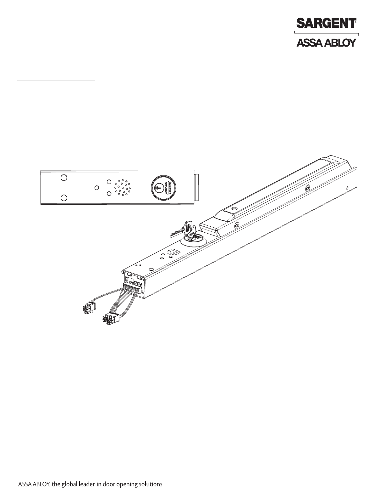
1. Description
Part of the ASSA ABLOY LiteGuide family of products, the Beacon exit device provides both
audible and visible alerts to enhance the visibility of exit locations in dark or smoke-filled
passages and is intended as a supplement to existing codes for emergency egress lighting
and direction.
Connected to the building’s alarm system, an activated Beacon emits pulsing light followed by
an audible message declaring “Exit located here” in single or multiple languages. A highly visible
green laser light cone combined with the pulsing LEDs draws people directly to the exit.
Amber
Diagnostic
LED
Green
Laser
Green
Ready-State
LED
Fig. 1 BEACON Exit Device
White
High-Intensity
LED
White
High-Intensity
LED
Speaker
Cylinder
Innovative design protected by
U.S. Patent Nos. 7,839,265 & 7,528,700
The SARGENT Beacon (BT-) Exit Device is compatible with the following prefix:
• TL- (SARGuide): Illuminated touchpad for 80 Series exit devices.
FOR INSTALLATION ASSISTANCE CONTACT SARGENT • 1-800-810-WIRE (9473) • www.sargentlock.com
A7974C 3
Copyright © 2009 Sargent Manufacturing Company, an ASSA ABLOY Group company. All rights reserved.
Reproductions in whole or in part without express written permission of Sargent Manufacturing Company is prohibited.
02/01/13
Page 4
Installation and Wiring Instructions
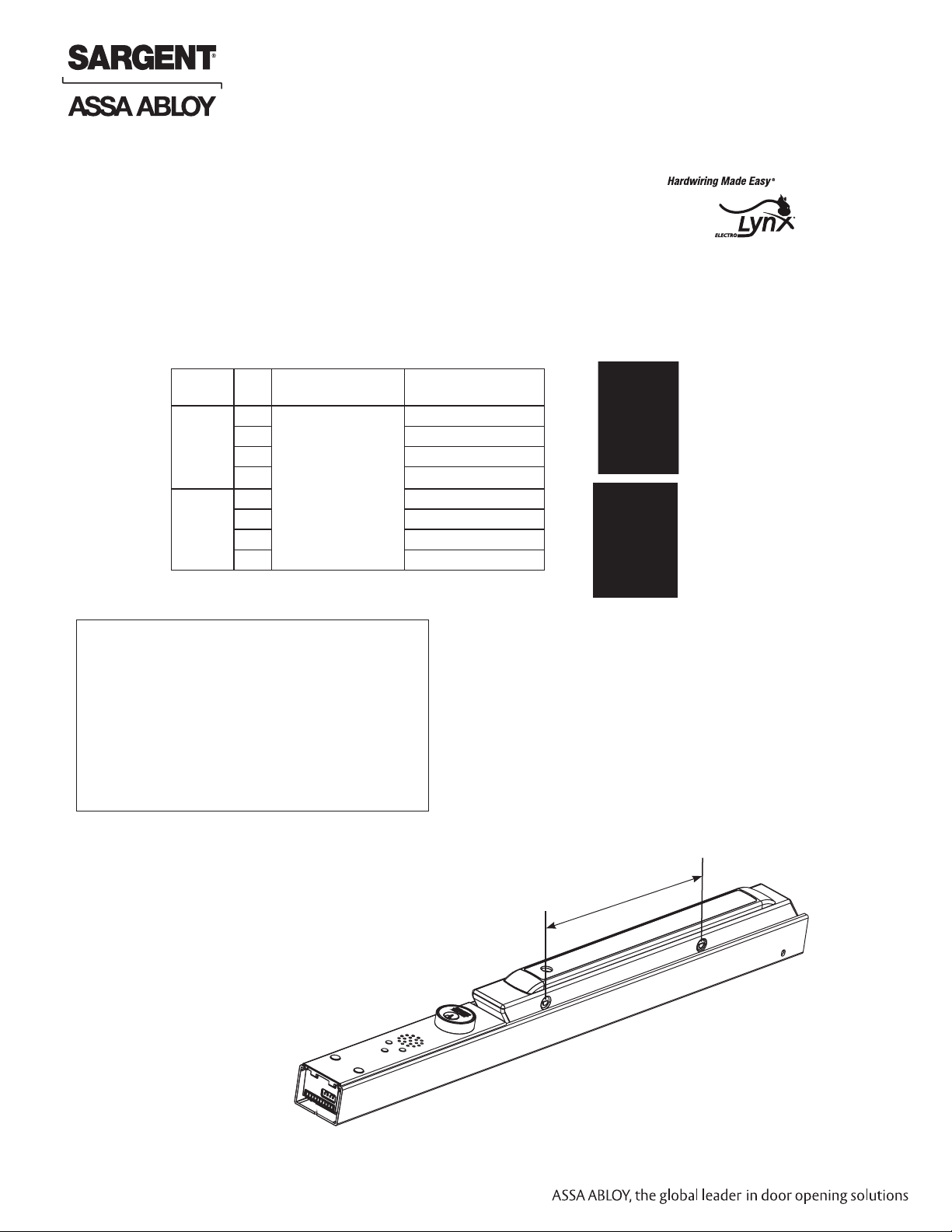
2. Hardware Specifications
• Easily installed within all 80 Series Exit Devices as either a retrofit kit or
as a factory installed option (consult catalog for exceptions).
• Order kit as 548-Kit (x door width x finish). See table below.
• Order factory installed option as BT- (e.g. BT-8813F x ETL x 32D x 36” door)
• Door Widths: Minimum Wide Stile Door 32”
• Convenient wiring installation with ElectroLynx 8-pin & 4-pin connectors*
*ElectroLynx door & frame wire harnesses and power transfer devices must be ordered separately.
Refer to McKinney Power Transfer Device Catalog for further information.
Beacon Exit Device
Stile Rail
Size
Wide E
F 35”- 36”
J 38”- 42”
G 44”- 48”
Narrow E 30”- 32”
F 33”- 36”
J 37”- 42”
G 43”- 48”
Type of
Exit Device
80 Series Exit
Devices
Note: The Beacon Retrofit Kits can NOT be
added to FM8700 Devices, Low Profile Exits
and devices with Cylinder Dogging (16-).
548- Retrofit Kits replace Beacon BT- ONLY
products (without other electrical prefixes).
For existing TL- BT-, consult factory.
The Retrofit Kits are based on rail design
(wide or narrow) and dimension from pivot
to pivot.
Size
Door
32” only
Wide Stile
Narrow Stile
Kit # Device Stile Rail Size Pivot to Pivot
548-1 Wide F 11-1/4”
548-2 Narrow F 11-1/4”
548-3 Wide G 20-1/2”
548-4 Narrow G 20-1/2”
548-5 Wide E 8-1/2”
548-6 Narrow E 8-1/2”
548-7 Wide J 14”
548-8 Narrow J 14”
*
Field-cut rail assemblies are not allowed.
The exit device must be ordered from
factory for specific door widths.
Copyright © 2013 Sargent Manufacturing Company, an ASSA ABLOY Group company. All rights reserved.
Reproductions in whole or in part without express written permission of Sargent Manufacturing Company is prohibited.
FOR INSTALLATION ASSISTANCE CONTACT SARGENT • 1-800-810-WIRE (9473) • www.sargentlock.com
02/01/13
4 A7974C
*Pivot-to-Pivot
Dimension
Fig. 2
Page 5
Beacon Exit Device
Installation and Wiring Instructions
3. Electrical Specifications
• Accepts alarm signal from either dry contact relay or 24VDC from the Notification Appliance Circuit
(NAC) of a Fire Alarm Control Panel (FACP)
• Low current draw 30mA @ 24VDC in Standby Mode, 900mA max @24VDC in Alarm Mode ensures long
operation time on back-up batteries. Power supply required; 24VDC, 1.0 amp, filtered and regulated.
• Test mode and diagnostic trouble reporting for ease of installation and periodic functional checks
• Customizable functionality through on-board adjustment of dip switch and NAC/CC slide switch settings
• Centralized control from fire alarm control panel (FACP) with silence and reset commands
• AHJ (Authority Having Jurisdiction) needs to authorize setup
Caution:
1. Disconnect all input power before beginning installation to prevent electrical shock and
equipment damage.
2. Installer must be a trained, qualified service person.
3. All wiring must comply with applicable local electrical codes, ordinances and regulations.
4. Beacon is equipped with a Class IIIa 5mW max output power (Green) laser.
Warning: Do NOT stare into laser beam.
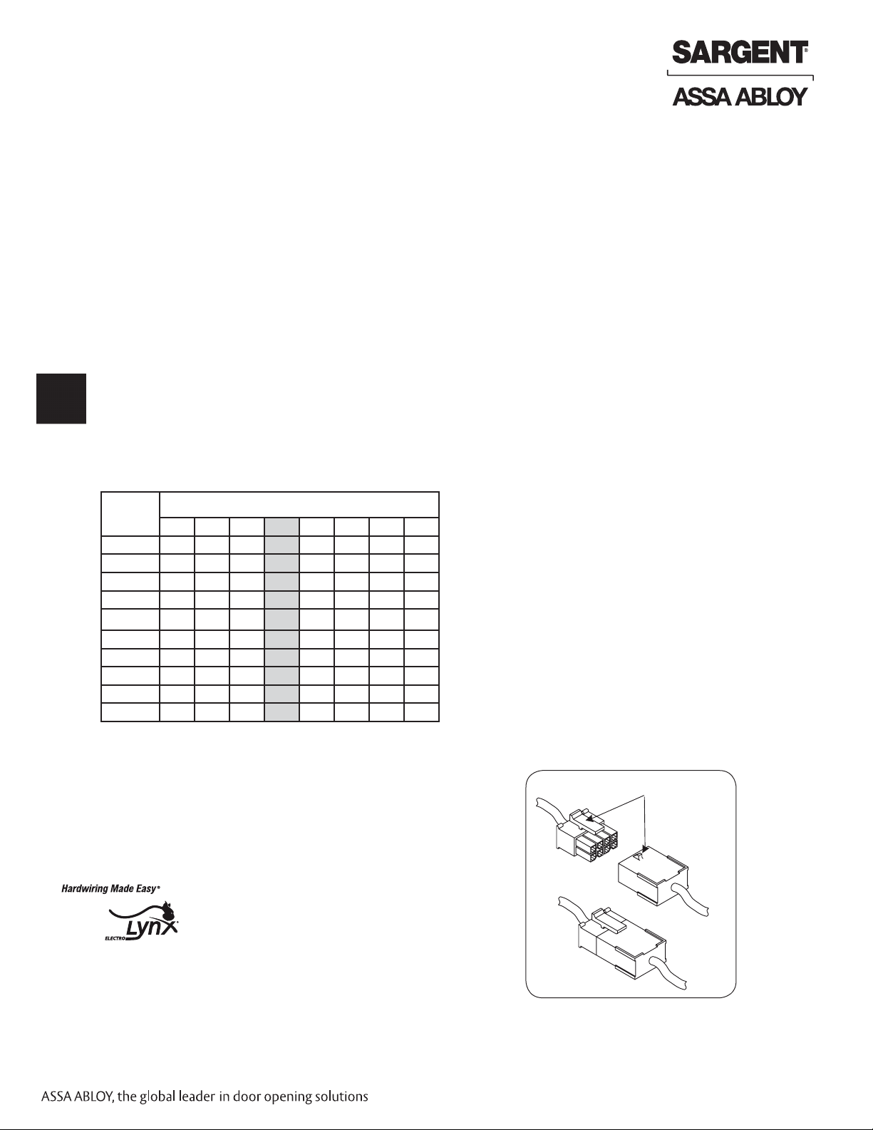
4. Wire Gauge Chart
Total
One-Way
Length of
Wire Run (ft)
1/4A 1/2A 3/4A *1A 1-1/4A 1-1/2A 2A 3A
100 24 20 18 18 16 16 14 12
150 22 18 16 16 14 14 12 10
200 20 18 16 14 14 12 12 10
250 18 16 14 14 12 12 12 10
300 18 16 14 12 12 12 10 —
400 18 14 12 12 10 10 — —
500 16 14 12 10 10 — — —
750 14 12 10 10 — — — —
1,000 14 10 10 — — — — —
1,500 12 10 — — — — — —
Load Current @ 24VDC
5. ElectroLynx Wiring System
BEACON exit devices are supplied with one 4-pin and one
8-pin Molex® connector harness, allowing simple installation
using the ASSA ABLOY ElectroLynx® system.
IMPORTANT: ElectroLynx connectors plug and
lock together in only one way.
Do NOT force connectors together.
*When calculating voltage drop, use 1A as the
recommended current draw for the BEACON
NOTE: For wire locations and positions, see
wiring examples later in this document.
Locking Mechanism
Plug
Receptacle
Fig. 3 ElectroLynx Connections
FOR INSTALLATION ASSISTANCE CONTACT SARGENT • 1-800-810-WIRE (9473) • www.sargentlock.com
A7974C 5
Copyright © 2009 Sargent Manufacturing Company, an ASSA ABLOY Group company. All rights reserved.
Reproductions in whole or in part without express written permission of Sargent Manufacturing Company is prohibited.
02/01/13
Page 6
Installation and Wiring Instructions
SECTION II: Installation Instructions
1. New Installation
Rail assembly is shipped with cylinder installed.
A. If cylinder does not need to be replaced, verify proper switch settings for
your facility in Section II.4 - Alarm Mode Operation/Dip Switch Settings
and Section II.5 - Alarm Notification Switch Setting (NAC/CC).
B. If replacing cylinder, go to Section II.3 - Cylinder Installation/Replacement.
C. Complete wiring connections - refer to this manual’s example
wiring diagrams (Section III) for proper connections.
D. Refer to 80 Series installation instructions and complete
exit device installation.
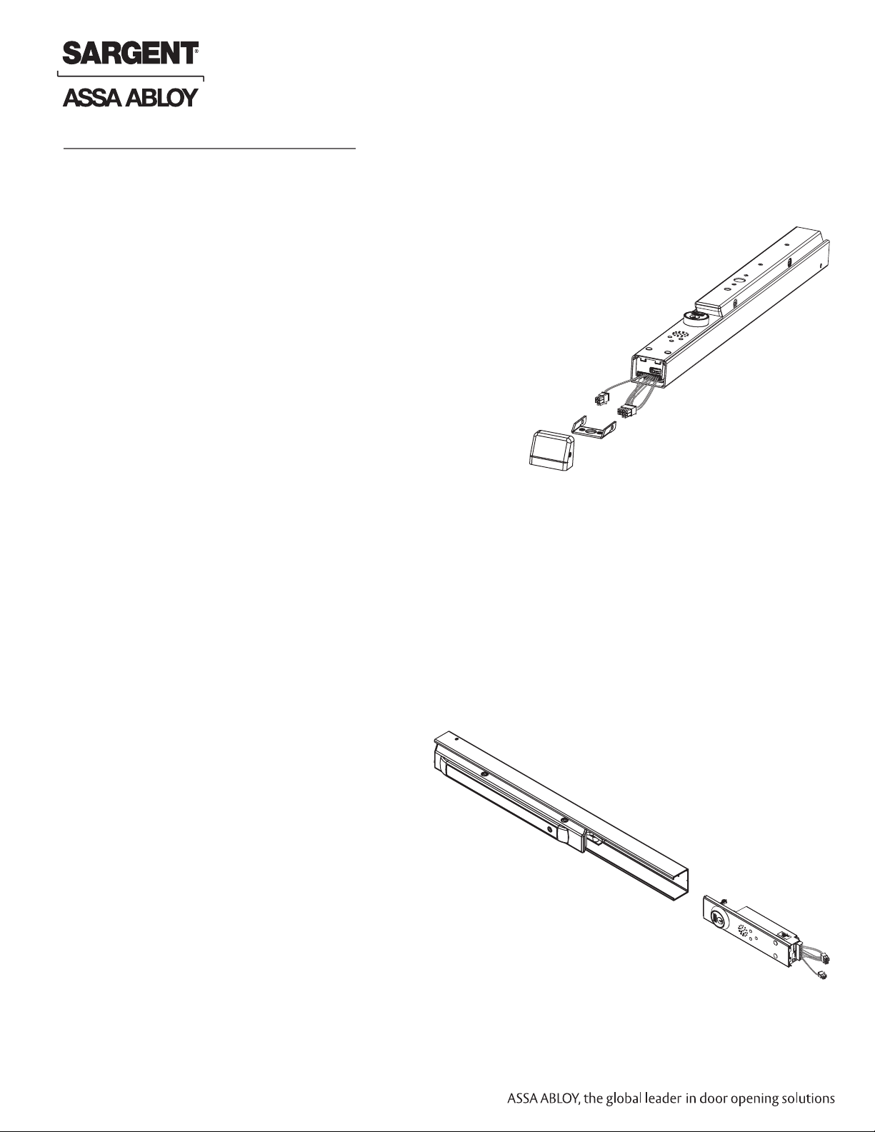
Beacon Exit Device
Mounting Bracket
End Cap
2. Kit Installation - Replacement/Servicing
If installing new Beacon insert assembly on existing mechanical rail:
A. Remove end cap and mounting bracket from rail assembly.
B. Remove insert plate by sliding out from rail assembly.
C. If replacing cylinder, go to Section II.3 - Cylinder Installation/Replacement.
D. Slide Beacon insert assembly into rail assembly (Fig. 5).
E. Complete wiring connections - refer to
this manual’s example wiring diagrams in
Section III for proper connections.
F. Reinstall mounting bracket and end cap.
Fig. 5
Rail Assembly
Fig. 4
Copyright © 2013 Sargent Manufacturing Company, an ASSA ABLOY Group company. All rights reserved.
Reproductions in whole or in part without express written permission of Sargent Manufacturing Company is prohibited.
FOR INSTALLATION ASSISTANCE CONTACT SARGENT • 1-800-810-WIRE (9473) • www.sargentlock.com
02/01/13
6 A7974C
Beacon Insert Assembly
Page 7

Beacon Exit Device
Installation and Wiring Instructions
2. Kit Installation - Replacement/Servicing (Continued)
If installing new Beacon insert assembly on existing Beacon (BT- only) electro-mechanical rail:
A. NOTE: Remove power from device.
B. Remove end cap and mounting bracket.
C. Slowly slide insert assembly (2 inches) away from push bar (Fig. 6), carefully checking for any
additional wires required for TL- prefix.
Fig. 6
D. Disconnect all wiring connectors before attempting to fully remove Beacon insert assembly.
E. Remove insert assembly by sliding out from rail assembly.
F. If replacing cylinder, go to Section II.3 - Cylinder Installation/Replacement.
NOTE: For TL-BT-, retain existing Beacon harness for reuse.
G. Slide new Beacon insert assembly into rail assembly.
H. Complete wiring connections - refer to this manual’s example wiring diagrams in Section III for
proper connections.
I. Reinstall mounting bracket and end cap.
FOR INSTALLATION ASSISTANCE CONTACT SARGENT • 1-800-810-WIRE (9473) • www.sargentlock.com
A7974C 7
Copyright © 2009 Sargent Manufacturing Company, an ASSA ABLOY Group company. All rights reserved.
Reproductions in whole or in part without express written permission of Sargent Manufacturing Company is prohibited.
02/01/13
Page 8

3. Cylinder Installation/Replacement
To install or replace cylinder, Beacon insert assembly
must be removed from exit device.
NOTE: Remove power from device.
A. If necessary, remove end cap and mounting bracket.
B. Slowly slide insert assembly (partially) away from push
bar (Fig. 7), carefully checking for any additional wires
required for TL- prefix.
NOTE: Disconnect all wiring connectors before
attempting to fully remove insert assembly.
Beacon Exit Device
Installation and Wiring Instructions
Fig. 7
C. Remove insert assembly from exit device.
D. Rotate cylinder nut counter clockwise and remove (Fig. 8).
E. Remove cylinder and collar (Fig. 8).
NOTE: Use factory-supplied rings and collars.
F. Install cylinder with cylinder cam in proper
position. Cam must be positioned so that it makes
solid contact with plastic switch actuator when
rotated (Fig. 9).
Note: Cylinder must be installed as shown for
proper switch operation.
G. Complete wiring connections - refer to this
manual’s example wiring diagrams in Section III
for making the proper connections.
H. Install mounting bracket and end cap.
I. Refer to 80 Series installation instructions and
complete exit device installation.
Nut
Cylinder & Collar
Plastic Switch Actuator
Beacon
Insert Assembly
Fig. 8
Copyright © 2013 Sargent Manufacturing Company, an ASSA ABLOY Group company. All rights reserved.
Reproductions in whole or in part without express written permission of Sargent Manufacturing Company is prohibited.
FOR INSTALLATION ASSISTANCE CONTACT SARGENT • 1-800-810-WIRE (9473) • www.sargentlock.com
02/01/13
8 A7974C
Cam rotates to
Fig. 9
engage actuator
Page 9

Beacon Exit Device
Installation and Wiring Instructions
4. Alarm Mode Operation/Dip Switch Settings
A. Verify settings are correct for your facility’s
requirements.
NOTE: Device is shipped with factory default settings
(all switches ON - see Fig. 10 below).
Visual and audio (voice messages) will repeat sequence
in Alarm Mode.
If dip switch settings need to be changed from the factory
default, set according to chart (Fig. 11).
Two White
High-Intensity
LEDs
5 6
ON
English
Message
1 2
Fig. 10
Spanish
Message
French
Message
3 4
OFF
ON
Door
Surface
Not Used Green
1 2 3 4 5 6
Laser
Alarm Mode Operation Dip Switch Settings
• Two (2) WHITE LEDs flash continuously
• GREEN Laser ON 3 seconds
• ENGLISH message followed by
• GREEN Laser ON 3 seconds
• SPANISH message followed by
• GREEN Laser ON 3 seconds
• FRENCH message
• Two (2) WHITE LEDs flash continuously
• GREEN Laser ON 3 seconds
• ENGLISH message followed by
• GREEN Laser ON 3 seconds
• SPANISH message followed by
• Two (2) WHITE LEDs flash continuously
• GREEN Laser ON 3 seconds
• ENGLISH message only
• Two (2) WHITE LEDs flash continuously
• ENGLISH message followed by
• SPANISH message followed by
• FRENCH message
• (NO Green LASER)
• NO White LEDs
• GREEN Laser ON 3 seconds
• ENGLISH message followed by
• GREEN Laser ON 3 seconds
• SPANISH message followed by
• GREEN Laser ON 3 seconds
• FRENCH message
• NO White LEDs
• ENGLISH message followed by
• SPANISH message followed by
• FRENCH message
• (NO Green LASER)
• Trouble condition #4
• AMBER LED blinks 4 times and repeats
ON
1 2
Default Settings
ON
1 2
ON
1 2
ON
1 2
ON
1 2
ON
1 2
ON
1 2
3 4
3 4
3 4
3 4
3 4
3 4
3 4
5 6
5 6
5 6
5 6
5 6
5 6
5 6
5. Alarm Notification Switch Setting (NAC/CC)
Factory default for NAC/CC switch is set to
CC (closed contact).
To change Beacon to NAC Alarm Mode:
A. Flip unit; slide insert assembly out 2 inches (Fig. 12).
B. Set the device for NAC by moving the slide switch
to the left, as shown in Figure 12.
C. Once switch is in proper position, slide insert
assembly back into rail assembly.
D. Refer to Section III NAC wiring examples
for proper wiring of NAC (vs. CC).
FOR INSTALLATION ASSISTANCE CONTACT SARGENT • 1-800-810-WIRE (9473) • www.sargentlock.com
Fig. 11
Fig. 12
A7974C 9
Copyright © 2009 Sargent Manufacturing Company, an ASSA ABLOY Group company. All rights reserved.
Reproductions in whole or in part without express written permission of Sargent Manufacturing Company is prohibited.
02/01/13
Page 10

Beacon Exit Device
Installation and Wiring Instructions
SECTION III: Beacon Wiring Examples
Wiring diagram examples reflect ElectroLynx system application.
For additional ElectroLynx product (door harnesses, power transfer devices, and frame harness) information and
requirements, refer to McKinney Power Transfer Device Catalog.
ElectroLynx power transfer device and harness requirement for all Beacon applications is QC12.
Beacon
TB1
1 + DC IN
2 -
3 + IN/CC
4 -
5 + RET
6 -
7 + SIL
8 -
Termination Description
Beacon Input Power: 24VDC (1.0 Amp minimum) from FACP (Fire Alarm Control Panel).
Beacon will operate from 16 to 33VDC.
Beacon Alarm input from FACP. Two choices: NAC IN (NAC) 24VDC (8 to 33VDC) or dry contact
closure (CC) sets Beacon into Alarm Mode. Set NAC/CC switch on Beacon module to NAC or CC
according FACP wiring application.
Additional Alarm signal connections for interconnectiing multiple Beacon rail assemblies
Beacon Silence input signal from FACP. Purpose is to stop Beacon audible (voice messages) during
a fire alarm so emergency personnel can listen to their radios. A valid silence condition occurs when
24vdc (8 to 33VDC) signal is present on the Silence Input for >= 500 msec, and is then removed for
>= 125 msec.
Simplified Diagram of an In-building Commercial Fire Alarm System
(excludes fire suppression and central station controls)
Copyright © 2013 Sargent Manufacturing Company, an ASSA ABLOY Group company. All rights reserved.
Reproductions in whole or in part without express written permission of Sargent Manufacturing Company is prohibited.
FOR INSTALLATION ASSISTANCE CONTACT SARGENT • 1-800-810-WIRE (9473) • www.sargentlock.com
02/01/13
10 A7974C
Page 11

Beacon Exit Device
Installation and Wiring Instructions
Example: NON-Addressable Fire Alarm System with BEACON
(Diagram ignores Initiating Devices)
NAC - Notification Appliance
Circuit
FOR INSTALLATION ASSISTANCE CONTACT SARGENT • 1-800-810-WIRE (9473) • www.sargentlock.com
A7974C 11
Copyright © 2009 Sargent Manufacturing Company, an ASSA ABLOY Group company. All rights reserved.
Reproductions in whole or in part without express written permission of Sargent Manufacturing Company is prohibited.
02/01/13
Page 12

Beacon Exit Device
Installation and Wiring Instructions
Example: Addressable Fire Alarm System with BEACON
(Diagram ignores Initiating Devices)
NAC - Notification Appliance Circuit
SLC - Signalling Line Circuit
CC - (dry) Contact Closure
Copyright © 2013 Sargent Manufacturing Company, an ASSA ABLOY Group company. All rights reserved.
Reproductions in whole or in part without express written permission of Sargent Manufacturing Company is prohibited.
FOR INSTALLATION ASSISTANCE CONTACT SARGENT • 1-800-810-WIRE (9473) • www.sargentlock.com
02/01/13
12 A7974C
Page 13

Beacon Exit Device
Installation and Wiring Instructions
Example Wiring Diagram: BT- Beacon Exit Device
ElectroLynx Application
Must connect to Earth
Ground (EGND)
*
*
*
*
QC12
FOR INSTALLATION ASSISTANCE CONTACT SARGENT • 1-800-810-WIRE (9473) • www.sargentlock.com
A7974C 13
Copyright © 2009 Sargent Manufacturing Company, an ASSA ABLOY Group company. All rights reserved.
Reproductions in whole or in part without express written permission of Sargent Manufacturing Company is prohibited.
02/01/13
Page 14

Example Wiring Diagram: TL- BT- (Beacon)
Exit Device ElectroLynx Application
Beacon Exit Device
Installation and Wiring Instructions
For TL- option, additional
External Power Supply
needed
Must connect to Earth
Ground (EGND)
*
*
QC12
Black,
Copyright © 2013 Sargent Manufacturing Company, an ASSA ABLOY Group company. All rights reserved.
Reproductions in whole or in part without express written permission of Sargent Manufacturing Company is prohibited.
FOR INSTALLATION ASSISTANCE CONTACT SARGENT • 1-800-810-WIRE (9473) • www.sargentlock.com
02/01/13
Red,
14 A7974C
Page 15

Beacon Exit Device
Installation and Wiring Instructions
SECTION IV: Alarm Mode Operation
Alarm Mode operates according to Dip Switch/Configuration Settings (Section II.4) and NAC/CC Switch
Setting (Section II.5)
1. Upon power up, the Green LED will light (Standby Mode).
2. When alarm is activated via a fire alarm, Beacon will activate.
3. Beacon will respond according to switch settings (see Section II.4) using:
• Flashing high intensity LEDs
• Audible message (Factory programmed)
• Laser (Green)
Amber
Diagnostic
LED
Green
Laser
Green
Ready-State
LED
White
High-Intensity
LED
White
High-Intensity
LED
Speaker
Cylinder
CAUTION: Do not stare into laser beam
4. Beacon will remain in Alarm Mode until manually reset by the cylinder (keyswitch rotated fully clockwise to
stop for >= two (2) seconds) or after power/alarm reset.
5. Upon reset, Beacon will return to Standby Mode/Ready State.
SECTION V: Test Mode Operation
Test Mode Features
Sequence of operation (from Standby Mode):
• Green LED is ON, key switch is operated by rotating fully clockwise (until stop) for >= 5 seconds.
Do NOT overtorque key switch. Green LED flashes 5 times then stays ON.
• Amber LED is OFF, flashes 6 times, ON
• Two high intensity LED’s are OFF, both flash 4 times, then OFF
• Green Laser is OFF, ON for 4 seconds, OFF
CAUTION: Do not stare into laser beam
• Voice messages play: English, Spanish, French
• Voice message: Test Mode Complete
• Green LED remains ON (back to Standby Mode)
FOR INSTALLATION ASSISTANCE CONTACT SARGENT • 1-800-810-WIRE (9473) • www.sargentlock.com
A7974C 15
Copyright © 2009 Sargent Manufacturing Company, an ASSA ABLOY Group company. All rights reserved.
Reproductions in whole or in part without express written permission of Sargent Manufacturing Company is prohibited.
02/01/13
Page 16

Beacon Exit Device
Installation and Wiring Instructions
SECTION VI: BEACON Modes of Operation
Mode Description What Happens Initiated by: Deactivated by
Active/
Standby
Test
Alarm
Silence
Trouble
This mode can be
considered the idle state.
(Notification Alarms are shut
off in this mode)
A temporary state where the
Beacon will perform a selftest.
Beacon alarms in response
to fire alarm system outputs.
Overrides audible notification
during a fire alarm so that
emergency personnel can
listen to their radios.
Problem with operation,
setup or wiring
Green LED is ON. This is the default power on
Audio messaging will
play every message
once, followed by
“Test Mode Complete”
message.
All Visual Notification
including the high
brightness LEDs will
flash and laser cone
will illuminate for four
seconds.
Audio messaging will
play according to dip
switch settings.
High Brightness LEDs
and laser cone will
illuminate according to
dip switch settings.
state.
(Beacon is connected and
powered)
Rotating key switch clockwise
(to stop) for five seconds,
then releasing
Fire alarm system outputs Automatically returns to
Beacon comes out of
Active Mode whenever
another mode is triggered
Automatically returns to
Active Mode after cycling
Active Mode when:
• key switch is fully
rotated for two seconds, then released
• FACP alarm input is
inactive for two or
more seconds
See Silence Mode (below)
Audio messaging will
not play.
High Brightness LEDs
and laser cone will
illuminate according to
dip switch settings.
Blinking Amber LED Internal diagnostics See following section on
A silence condition can occur
only during ALARM MODE:
When Beacon’s Silence
input receives a valid
silence condition from FACP,
8-33VDC is present on the
Silence Input for >= 500ms,
and then removed for >=
125ms
Beacon alarm input is
inactive for two or more
seconds
NOTE: Audio messages
return if Silence input to
Beacon receives 8-33VDC
signal from FACP
When key switch is rotated
fully clockwise (to stop)
for two seconds, then
released, Alarm Mode is
turned off and unit returns
to Active state (Silence
Mode is turned off)
trouble conditions
Copyright © 2013 Sargent Manufacturing Company, an ASSA ABLOY Group company. All rights reserved.
Reproductions in whole or in part without express written permission of Sargent Manufacturing Company is prohibited.
FOR INSTALLATION ASSISTANCE CONTACT SARGENT • 1-800-810-WIRE (9473) • www.sargentlock.com
02/01/13
16 A7974C
Page 17

Beacon Exit Device
Installation and Wiring Instructions
Trouble Conditions and Corrective Actions
Fault Condition Fault Corrective Action
Blink Amber trouble LED
using repeating Blink *1
pattern.
*A 1 second blink with a 5
second pause.
Input power under
16VDC**
Correct input voltage to 24VDC (nominal);
(operates from 16-33VDC)
Blink Amber trouble LED
using repeating Blink 2*
pattern.
*Two 1 second blinks with a
5 second pause.
Blink Amber trouble LED
using repeating Blink 3*
pattern.
*Three 1 second blinks with
a 5 second pause.
Blink Amber trouble LED
using repeating Blink 4*
pattern.
*Four 1 second blinks with
a 5 second pause.
Blink Amber trouble LED
using repeating Blink 5*
pattern.
*Five 1 second blinks with a
5 second pause.
Laser over current
condition**
Motor over current
condition**
Invalid DIP switch
configuration
All DIP switches are OFF**
Key switch stuck error**
If key switch is detected as
turned for >= 30 seconds.
Replace Beacon Insert Assembly
Replace Beacon Insert Assembly
Refer to DIP Switch Setting/Configuration
Section II.4 for valid switch selections.
Inspect operation of cylinder cam with
Beacon plastic switch actuator.
Free possible obstruction or replace
Beacon Insert Assembly if inoperable.
**Disables all audible and visual notification alerts.
FOR INSTALLATION ASSISTANCE CONTACT SARGENT • 1-800-810-WIRE (9473) • www.sargentlock.com
A7974C 17
Copyright © 2009 Sargent Manufacturing Company, an ASSA ABLOY Group company. All rights reserved.
Reproductions in whole or in part without express written permission of Sargent Manufacturing Company is prohibited.
02/01/13
Page 18

SARGENT Manufacturing
100 Sargent Drive
New Haven, CT 06511 USA
800-810-WIRE (9473) • www.sargentlock.com
Founded in the early 1800s, SARGENT® is a market leader in locksets, cylinders, door closers, exit devices,
electro-mechanical products and access control systems for new construction, renovation, and replacement applications.
The company’s customer base includes commercial construction, institutional, and industrial markets.
Copyright © 2013, Sargent Manufacturing Company, an ASSA ABLOY Group company. All rights reserved.
Reproduction in whole or in part without the express written permission of Sargent Manufacturing Company is prohibited.
ASSA ABLOY is the global leader in door opening solutions, dedicated to
satisfying end-user needs for security, safety and convenience.
A7974C - 2/13
 Loading...