

Sanyo DVD-SL33 User Manual
INSTRUCTION MANUAL
DVD Video Player
PICTURE
OPEN/CLOSE
LASTMEMO
z/ON
MODE
PROGRAM
REPEAT A-BREPEAT
/RANDOM
ANGLE
ZOOM ANGLE
ONSCREEN
SUBTITLE
CHANGE
SUBTITLE
ON/OFF
AUDIO
REVSLOW FWDSLOW
PREV NEXT
REV
123C
4560
789
SETUP MENU
4
ENT
TOPMENU
5
PAUSE/STEP
PLAY
REMOTECONTROLLER RB-SL22
REPLAY
RETURN
CLEAR
SEARCH
MODE
ab
FWD
q
OPEN/CLOSE
DVD-SL33
z/ONefan
1AD6P1P1928-(CA)
DVD-SL33/CA(English) 13/06/2003, 10:061
English

CONTENTS
Important Safety Instructions ............................................E3
Accessories .........................................................................E4
Controls ............................................................................... E5
Remote Control ...................................................................E6
Before Connection ..............................................................E7
Choosing a Connection .................................................. E7
Basic Connections ..............................................................E8
Connecting to a Conventional TV (Example 1) .............. E8
Connecting to a TV with Progressive-scan Capability
(Example 2) .................................................................. E10
Additional Connection Examples .................................... E11
Connecting to an Audio System and TV (Example 3) ...E11
Connecting to an Amplifier with Dolby Digital Decoder,
DTS Decoder or MPEG2 Decoder (Example 4)........... E12
Connecting to a Digital Amplifier (Example 5).............. E12
Connecting to an Amplifier with Dolby Pro Logic Decoder
(Example 6) .................................................................. E13
Power Supply ............................................................... E13
For Safe and Efficient Operation .....................................E13
Playable Discs ...................................................................E14
Basic Operation................................................................. E15
Preparations ................................................................. E15
Basic Playback ............................................................. E15
Stopping Playback........................................................ E16
Continuing Playback from Where You Stopped Watching
(LAST MEMO PLAY), for DVD only.............................. E16
Selecting a DVD Menu ................................................. E17
Selecting a Top Menu [DVD] ........................................ E17
Chapter (Track) Skip .................................................... E17
Title Search [DVD]........................................................ E18
Chapter Search [DVD].................................................. E18
Time Search [DVD]....................................................... E18
Time Search [CD] ......................................................... E18
Track Search [CD] ........................................................ E18
Fast Playback ............................................................... E19
Slow Motion Playback [DVD]........................................ E19
Still Picture (Pause)...................................................... E19
Frame by Frame Advance Playback [DVD].................. E19
Picture Zoom (Pin Point Zoom) [DVD] ......................... E20
Viewing from a Desired Camera Angle
(Multi-Angle) [DVD] ...................................................... E20
Angle Replay ................................................................ E20
Repeat Playback .......................................................... E21
Designated Range Repeat Playback (A-B Repeat) ..... E21
Random Playback [CD] ................................................ E22
Programmed Playback [CD]......................................... E22
Selecting Subtitle Language [DVD] .............................. E23
Selecting Audio Soundtrack Language
(Multi-Language) [DVD]................................................ E23
Selecting On-Screen Information ................................. E24
Selecting Picture Mode ................................................ E24
MP3 CD OPERATION ........................................................E25
Before Starting ................................................................... E25
MP3 CD Playback ........................................................ E25
Stopping Playback........................................................ E26
Pause ........................................................................... E26
File Skip........................................................................ E26
Repeat Playback .......................................................... E26
Picture Disc Operation ..................................................... E27
KODAK Picture CD Playback....................................... E27
JPEG CD Playback ...................................................... E28
Picture Zoom ................................................................ E28
Initial Settings .................................................................... E29
Setting Language ......................................................... E29
Setting Display ............................................................. E30
Setting Digital Out ........................................................ E31
Setting Parental............................................................ E32
Language Code List ..........................................................E33
Troubleshooting Guide ..................................................... E34
Maintenance ......................................................................E35
Specifications ....................................................................E35
Warranty ............................................................................. E36
Please Read This Manual.
Because DVD is a new technology, we recommend that you read this manual carefully before connecting your DVD
video player and operating it for the first time.
Keep the manual in a safe place for future reference.
IMPORTANT INFORMATION:
To connect this unit to a TV, TV must have a set of Audio/Video composite input jacks (RCA-type). You cannot use an
antenna terminal to connect this unit.
To enjoy Dolby Digital sound
For connection, see “Connecting to an Amplifier with Dolby Digital Decoder, DTS Decoder or MPEG2 Decoder (Example
4)” on page E12.
See “Setting Digital Out” in the INITIAL SETTINGS on page E31.
-E1-
DVD-SL33/CA(English) 13/06/2003, 10:062
CAUTION
RISK OF ELECTRIC SHOCK
DO NOT OPEN
This symbol indicates that dangerous voltage
constituting a risk of electric shock is present
within this unit.
CAUTION: TO PREVENT THE RISK OF ELECTRIC
SHOCK, DO NOT REMOVE COVER (OR BACK).
NO USER-SERVICEABLE PARTS INSIDE.
REFER SERVICING TO QUALIFIED SERVICE PERSONNEL.
WARNING: UNAUTHORIZED RECORDING OF COPY-
RIGHTED MATERIAL MAY VIOLATE APPLICABLE
COPYRIGHT LAWS. THE MANUFACTURER ASSUMES
NO RESPONSIBILITY FOR UNAUTHORIZED DUPLICA-
WARNING: TO PREVENT FIRE OR SHOCK
HAZARD, DO NOT EXPOSE THIS APPLIANCE TO
RAIN OR MOISTURE.
This symbol indicates that there are important
operating and maintenance instructions in the
literature accompanying this unit.
TION, USE OR OTHER ACTS WHICH INFRINGE UPON
THE RIGHTS OF COPYRIGHT OWNERS.
WARNING!
• UNAUTHORIZED RECORDING OF COPYRIGHT MATERIAL MAY VIOLATE APPLICABLE COPYRIGHT LAWS. THE MANUFACTURER
ASSUMES NO RESPONSIBILITY FOR UNAUTHORIZED DUPLICA TION, USE OR OTHER ACTS WHICH INFRINGE UPON THE RIGHTS OF
COPYRIGHT OWNERS.
• TO AVOID THE HAZARDS OF FIRE OR ELECTRICAL SHOCK, DO NOT EXPOSE THIS APPLIANCE TO RAIN OR OTHER MOISTURE.
• THE USE OF CONTROLS OR ADJUSTMENTS OR THE PERFORMANCE OF PROCEDURES OTHER THAN THOSE SPECIFIED HEREIN
MAY RESULT IN HAZARDOUS RADIATION EXPOSURE.
• THIS UNIT SHOULD NOT BE ADJUSTED OR REPAIRED BY ANYONE EXCEPT PROPERLY QUALIFIED SERVICE PERSONNEL.
THIS CLASS B DIGITAL APP ARATUS COMPLIES WITH CANADIAN ICES-003.
DVD-SL33/CA(English) 13/06/2003, 10:063
-E2-

IMPORTANT SAFETY INSTRUCTIONS
1. Read Instructions – All the safety and operating instructions
should be read before the product is operated.
2. Retain Instructions – The safety and operating instructions
should be retained for future reference.
3. Heed Warnings – All warnings on the product and in the
operating instructions should be adhered to.
4. Follow Instructions – All operating and use instructions
should be followed.
5. Cleaning – Unplug this product from the wall outlet before
cleaning. Do not use liquid cleaners or aerosol cleaners. Use a
damp cloth for cleaning.
6. Attachments – Do not use attachments not recommended
by the product manufacturer as they may cause hazards.
7. Water and Moisture – Do not use this product near water –
for example, near a bath tub, wash bowl, kitchen sink, or laundry
tub; in a wet basement; or near a swimming pool; and the like.
8. Accessories – Do not place this product on an unstable cart,
stand, tripod, bracket, or table. The product may fall, causing
serious injury to a child or adult, and serious damage to the
product. Use only with a cart, stand, tripod bracket, or table recommended by the manufacturer, or sold with the product. Any
mounting of the product should follow the manufacturer’s
instructions, and should use a mounting accessory recommended
by the manufacturer.
PORTABLE CART WARNING
(Symbol provided by RETAC)
9. A product and cart combination should
be moved with care. Quick stops, excessive
force, and uneven surfaces may cause the
product and cart combination to overturn.
10. Ventilation – Slots and openings in the cabinet are provided
for ventilation and to ensure reliable operation of the product
and to protect it from overheating, and these openings must not
be blocked or covered. The openings should never be blocked
by placing the product on a bed, sofa, rug, or other similar surface.
This product should not be placed in a built-in installation such
as a bookcase or rack unless proper ventilation is provided or
the manufacturer's instructions have been adhered to.
11. Power Sources – This product should be operated only from
the type of power source indicated on the marking label. If you
are not sure of the type of power supply to your home, consult
your product dealer or local power company. For products intended to operate from battery power, or other sources, refer to
the operating instructions.
12. Grounding or Polarization – This product may be equipped
with a polarized alternating-current line plug (a plug having one
blade wider than the other). This plug will fit into the power outlet
only one way. This is a safety feature. If you are unable to insert
the plug fully into the outlet, try reversing the plug. If the plug
should still fail to fit, contact your electrician to replace your obsolete outlet. Do not defeat the safety purpose of the polarized
plug.
13. Power-Cord Protection – Power-supply cords should be
routed so that are not likely to be walked on or pinched by items
placed upon or against them, playing particular attention to cords
at plugs, convenience receptacles, and the point where they exit
from the product.
14. Lightning – For added protection for this product during a
lightning storm, or when it is left unattended and unused for long
periods of time, unplug it from the wall outlet and disconnect the
antenna or cable system. This will prevent damage to the product due to lightning and power-line surges.
S3125A
(Figure 1)
-E3-
DVD-SL33/CA(English) 13/06/2003, 10:064
15. Outdoor Antenna Grounding – If an outside antenna or cable
system is connected to the product, be sure the antenna or cable
system is grounded so as to provide some protection against
voltage surges and built-up static charges. Article 810 of the
National Electrical Code, ANSI/NFPA 70, provides information
with regard to proper grounding of the mast and supporting
structure, grounding of the lead-in wire to an antenna discharge
unit, size of grounding conductors, location of antenna-discharge
unit, connection to grounding electrodes, and requirements for
the grounding electrode. See Figure 2.
EXAMPLE OF ANTENNA GROUNDING AS PER NATIONAL ELECTRICAL CODE, ANSI/NFPA 70
ANTENNA
GROUND
CLAMP
LEAD IN
WIRE
ANTENNA
DISCHARGE UNIT
(NEC SECTION 810-20)
ELECTRIC
SERVICE
EQUIPMENT
GROUNDING
CONDUCTORS
(NEC SECTION 810-21)
GROUND CLAMPS
POWER SERVICE GROUNDING
ELECTRODE SYSTEM
(NEC ART 250, PART H)
NEC – NATIONAL ELECTRICAL CODE
S2898A
(Figure 2)
16. Power Lines – An outside antenna system should not be
located in the vicinity of overhead power lines or other electric
light or power circuits, or where it can fall into such power lines
or circuits. When installing an outside antenna system, extreme
care should be taken to keep from touching such power lines or
circuits as contact with them might be fatal.
17. Overloading – Do not overload wall outlets, extension cords,
or integral convenience receptacles as this can result in a risk of
fire or electric shock.
18. Object and Liquid Entry – Never push objects of any kind
into this product through openings as they may touch dangerous
voltage points or short-out parts that could result in a fire or electric shock. Never spill liquid of any kind on the product.
19. Servicing – Do not attempt to service this product yourself
as opening or removing covers may expose you to dangerous
voltage or other hazards. Refer all servicing to qualified service
personnel.
20. Damage Requiring Service – Unplug this product from the
wall outlet and refer servicing to qualified service personnel under the following conditions:
a. When the power-supply cord or plug is damaged.
b. If liquid has been spilled, or objects have fallen into the
product.
c. If the product has been exposed to rain or water.
d. If the product does not operate normally by following the
operating instructions. Adjust only those controls that are
covered by the operating instructions as an improper adjustment of other controls may result in damage and will
often require extensive work by a qualified technician to
restore the product to its normal operation.
e. If the product has been dropped or damaged in any way.
f. When the product exhibits a distinct change in perfor-
mance – this indicates a need for service.
21. Replacement Parts – When replacement parts are required,
be sure the service technician has used replacement parts specified by the manufacturer or have the same characteristics as the
original part. Unauthorized substitutions may result in fire, electric shock, or other hazards.
22. Safety Check – Upon completion of any service or repairs
to this product, ask the service technician to perform safety checks
to determine that the product is in proper operating condition.
23. Heat – The product should be situated away from heat
sources such as radiators, heat registers, stoves, or other products (including amplifiers) that produce heat.
This appliance shall not be exposed to drippling or splashing
water and that no object filled with liquid such as vases shall be
placed on the apparatus.
PICTURE
OPEN/CLOSE
LASTMEMO
z/ON
MODE
PROGRAM
REPEAT A-B REPEAT
/RANDOM
ANGLE
ZOOM ANGLE
ONSCREEN
REPLAY
SUBTITLE
SETUP MENU
CHANGE
4
SUBTITLE
ON/OFF
ENT
ab
AUDIO RETURN
TOPMENU
5
REVSLOW FWDSLOW
PAUSE/STEP
PREV NEXT
PLAY
FWD
REV
CLEAR
123C
4560
SEARCH
MODE
789
REMOTECONTROLLERRB-SL22
DVD-SL33/CA(English) 13/06/2003, 10:065
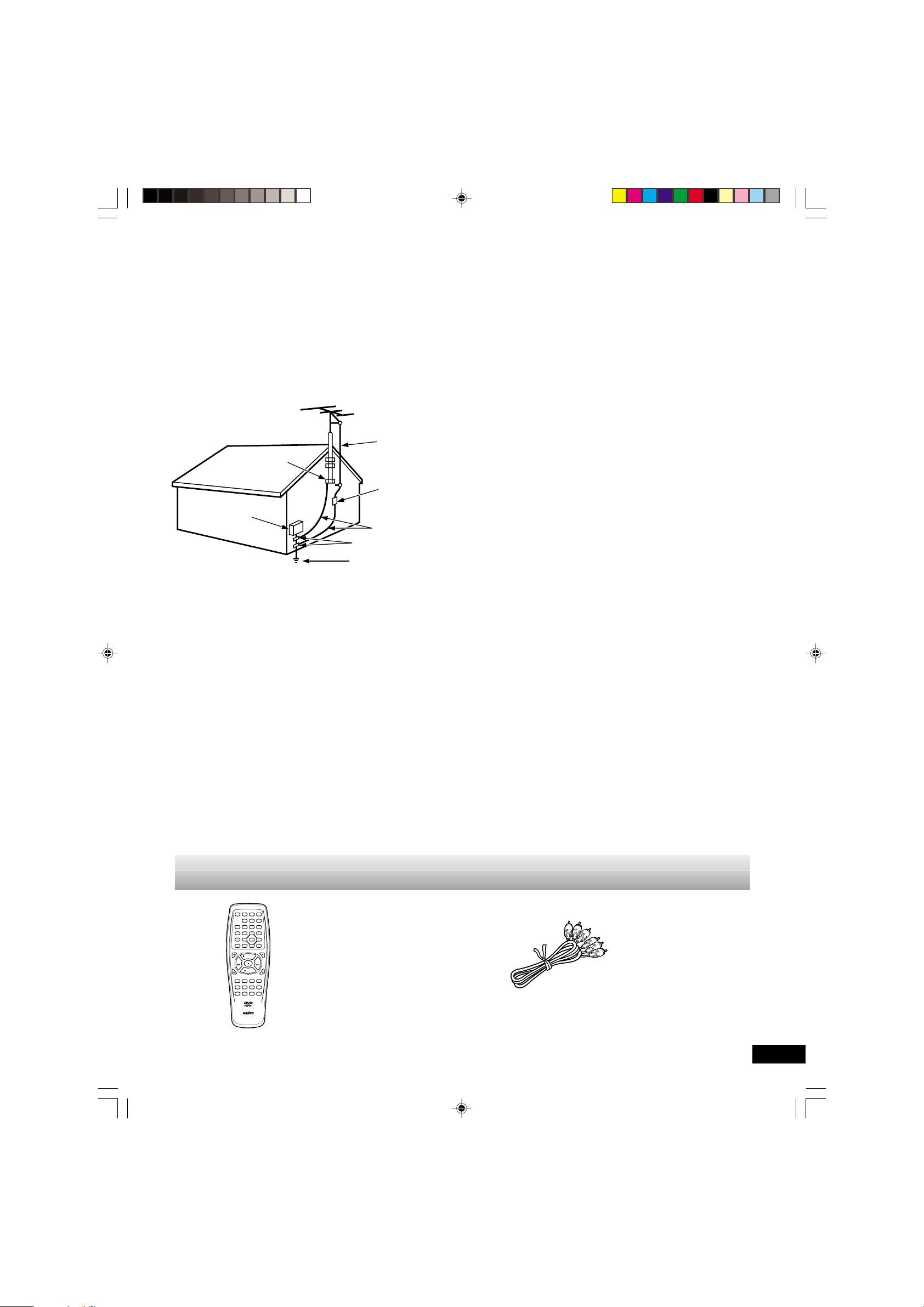
ACCESSORIES
Wireless remote control Audio/Video cable
-E4-
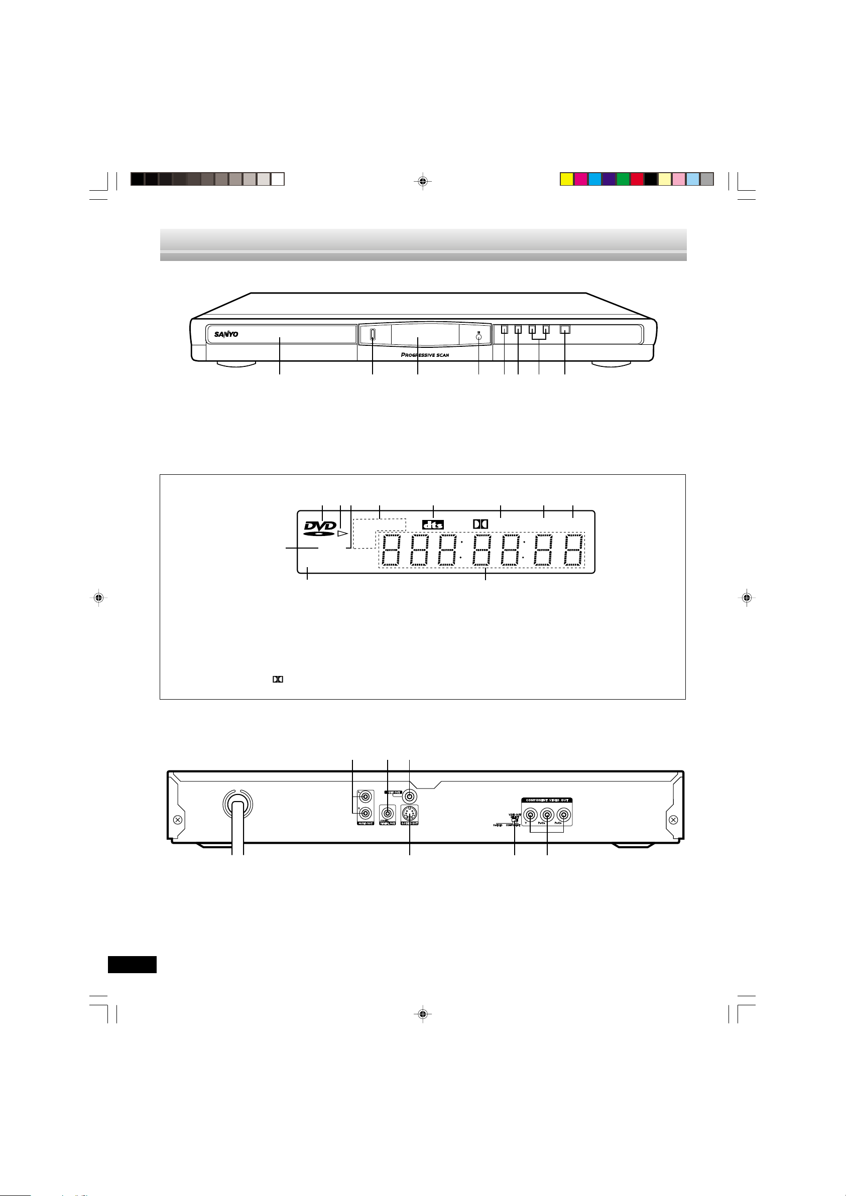
Front Panel
CONTROLS
q
OPEN/CLOSE
z/ONefan
12345
1. Disc tray
2. Open/Close button ( q )
3. FL display
4. Remote sensor (IR)
FL Display
12 54673
11
CD
MP3
1.DVD indicator ( DVD )
2.Play indicator ( a )
3.Pause indicator ( k )
4.Repeat mode indicators (REP, 1, ALL, A-B)
5.DTS indicator (dts)
6.Dolby Digital indicator (
Digital)
67 8
5. Stop button ( n )
6. Play button ( a )
7. Skip/Next/Previous buttons ( f, e )
8. Power button (z/ON)
8
ALLREP 1
A-B
k
Digital PGM
RND
910
7.Program indicator (PGM)
8.Random play indicator (RND)
9.Message or number indicators
(Title, cheaper, track, playing time or other information)
10.MP3 indicator (MP3)
11. CD indicator (CD)
Rear Panel
1. Audio output jacks (AUDIO OUT)
2. Coaxial digital output jack (DIGITAL OUT)
3. Video output jack (VIDEO OUT)
DVD-SL33/CA(English) 13/06/2003, 10:066
321
654
4. Component video output jacks (COMPONENT VIDEO OUT)
5. Video output select switch (VIDEO OUT SELECT)
6. S-Video output jack (S-VIDEO OUT)
-E5-
REMOTE CONTROL
32
30
28
25
22
31
29
27
26
24
23
21
20
12
LAST MEMO
z/ON
PROGRAM
/RANDOM
ZOOM ANGLE
ON SCREEN
SUBTITLE
SETUP MENU
CHANGE
SUBTITLE
ON/OFF
AUDIO
TOP MENU
REV SLOW FWD SLOW
PREV NEXT
REV
PICTURE
MODE
REPEAT A-B REPEAT
4
ENT
5
PAUSE/STEP
PLAY
3
OPEN/CLOSE
ANGLE
REPLAY
ab
RETURN
CLEAR
FWD
123C
4560
SEARCH
MODE
789
4
5
7
9
11
13
15
17
18
19
6
8
10
12
14
16
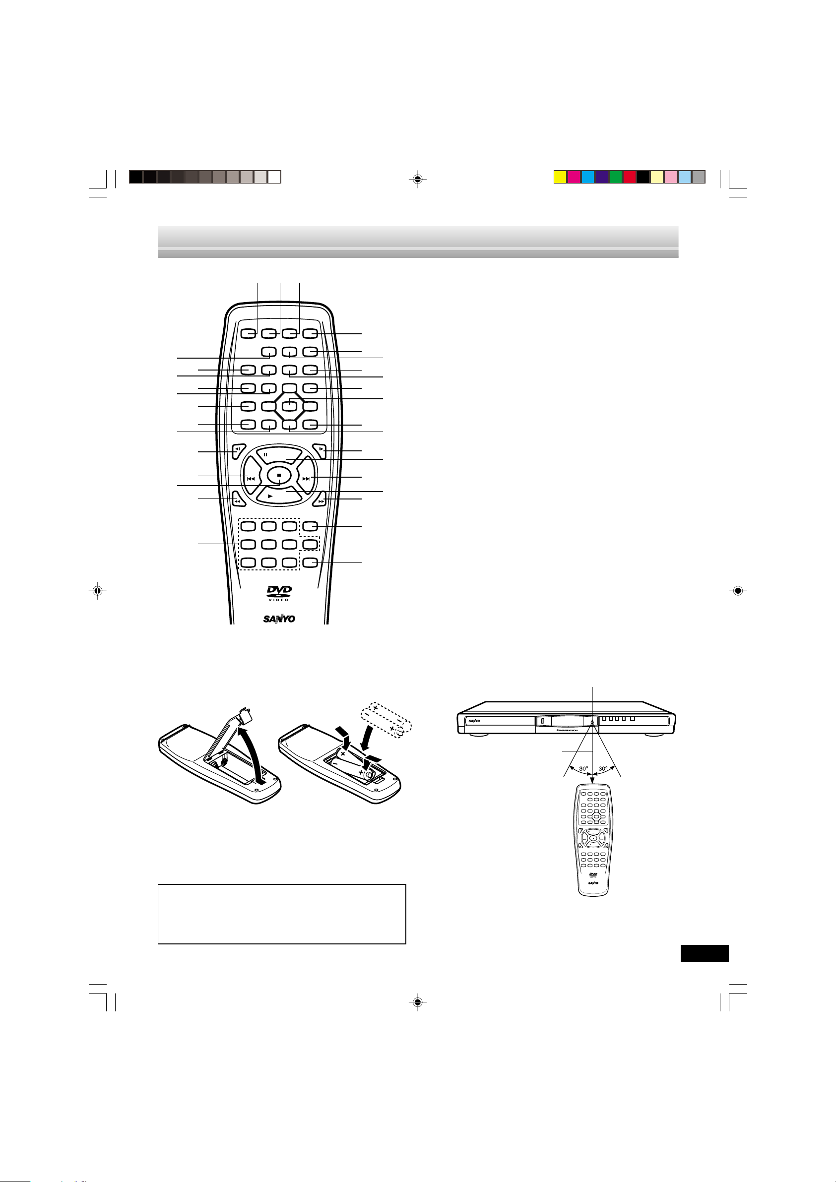
Controls
1.Power button (z/ON)
2.Last memory button (LAST MEMO)
3.Picture mode button (PICTURE MODE)
4.Open/Close button (OPEN/CLOSE)
5.A-B repeat button (A-B REPEAT)
6.Repeat button (REPEAT)
7.Angle replay button (ANGLE REPLAY)
8.Angle button (ANGLE)
9.Menu button (MENU)
10.Enter button (ENT)
11. Return button (RETURN) (See page E26.)
12.Directional arrow buttons (4, a, 5, b)
13.Forward slow button (FWD SLOW )
14.Pause/Step button (k PAUSE/STEP)
15.Skip/Next button (NEXT e)
16.Play button (a PLAY)
17.Forward button (FWD c)
18.Clear button (CLEAR)
19.Search mode button (SEARCH MODE)
20.Number buttons (1-9, 0)
21.Reverse button (REV d)
22.Stop button ( n )
23.Skip/Previous button (PREV f)
24.Reverse slow button (REV SLOW )
25.Top menu button (TOP MENU)
26.Audio button (AUDIO)
27.Subtitle On/Off button (SUBTITLE ON/OFF)
28.Setup button (SETUP)
29.Subtitle change button (SUBTITLE CHANGE)
30.Zoom button (ZOOM)
31.On screen display button (ON SCREEN)
32.Program/Random play button (PROGRAM/RANDOM)
q
q
Inserting batteries
1 2
Note:
Remove the batteries if the remote control is not to be used for a
month or more. Batteries left in the unit may leak and cause
damage.
Two “AA” batteries
(not supplied)
IMPORTANT NOTE:
SPENT OR DISCHARGED BATTERIES MUST BE RECYCLED OR DISPOSED OF PROPERLY IN COMPLIANCE
WITH ALL APPLICABLE LAWS.
FOR DETAILS INFORMATION, CONTACT YOUR LOCAL
COUNTY SOLID WASTE AUTHORITY.
Remote control range
Remote sensor
q
OPEN/CLOSE
Within approx. 23 feet (7 meters)
ONSCREEN
SUBTITLE
SUBTITLE
REVSLOW FWDSLOW
REV
Note:
This is not multibrand remote control.
PICTURE
LASTMEMO
z/ON
MODE
PROGRAM
REPEAT A-B REPEAT
/RANDOM
ZOOM ANGLE
SETUP MENU
CHANGE
4
ON/OFF
ENT
AUDIO RETURN
TOPMENU
5
PAUSE/STEP
PREV NEXT
PLAY
123C
4560
789
REMOTECONTROLLERRB-SL22
OPEN/CLOSE
REPLAY
SEARCH
z/ONefan
ANGLE
ab
FWD
CLEAR
MODE
DVD-SL33/CA(English) 13/06/2003, 10:067
-E6-

BEFORE CONNECTION
IMPORTANT INFORMATION:
• To connect this unit to a TV, TV must have a set of Audio/Video composite input jacks (RCA-type).
You cannot use an antenna terminal to connect this unit.
• If your TV has only an antenna terminal, please purchase the TV with Audio/Video input jacks or the RF modulator.
• Do not connect the unit to a VCR directly. The playback picture will be distorted because DVD video discs are copyprotected.
• Please refer to the instruction manuals for the components that you are connecting (TV, AV amplifier, etc.).
Choosing a Connection
Does your TV have “Audio/Video input jacks”?
x x x x x x x x x x x x
x
Yes No
x
TV Connection
x
TV and Amplifier Connection
x x x x
x
VIDEO Connection
x
AUDIO Connection
x
Do you use an RF Modulator (not supplied)?
Do you connect it to a Conventional
x
TV?
x
No
x
x x x x
x
No
x
Do you connect it to a TV with Progressive-scan Capability?
x x x x x x x x x x
x
Do you connect it to an Amplifier
with Dolby Digital Decoder, DTS
Decoder or MPEG2 Decoder?
x
x
Yes
x
See “Connecting to a Conventional TV
(Example 1)” and “Using RF Modulator” on pages E8 & E9.
Please purchase the TV with Audio/Video input jacks
or the RF Modulator.
x
Yes
x
See “Connecting to a Conventional TV
(Example 1)” on page E8.
x
Yes
x
See “Connecting to a TV with Progressive-scan Capability (Example 2)” on
page E10.
See “Connecting to a Conventional TV
(Example 1)”on page E8 or “Connecting to a TV with Progressive-scan
Capability (Example 2)” on page E10.
x
Yes
x
See “Connecting to an Amplifier with
Dolby Digital Decoder, DTS Decoder
or MPEG2 Decoder (Example 4)” on
page E12.
DVD-SL33/CA(English) 13/06/2003, 10:068
No
x
Do you connect it to a Digital
Amplifier?
No
x
x
Do you connect it to an Amplifier
with Dolby Pro Logic Decoder?
x
No
x
See “Connecting to an Audio
System and TV (Example 3)” on
page E11.
-E7-
x
x
Yes
Yes
x
x
See “Connecting to a Digital Amplifier
(Example 5)” on page E12.
See “Connecting to an Amplifier with
Dolby Pro Logic Decoder (Example 6)”
on page E13.
BASIC CONNECTIONS
COMPONENT VIDEOINPUT
YPBP
R
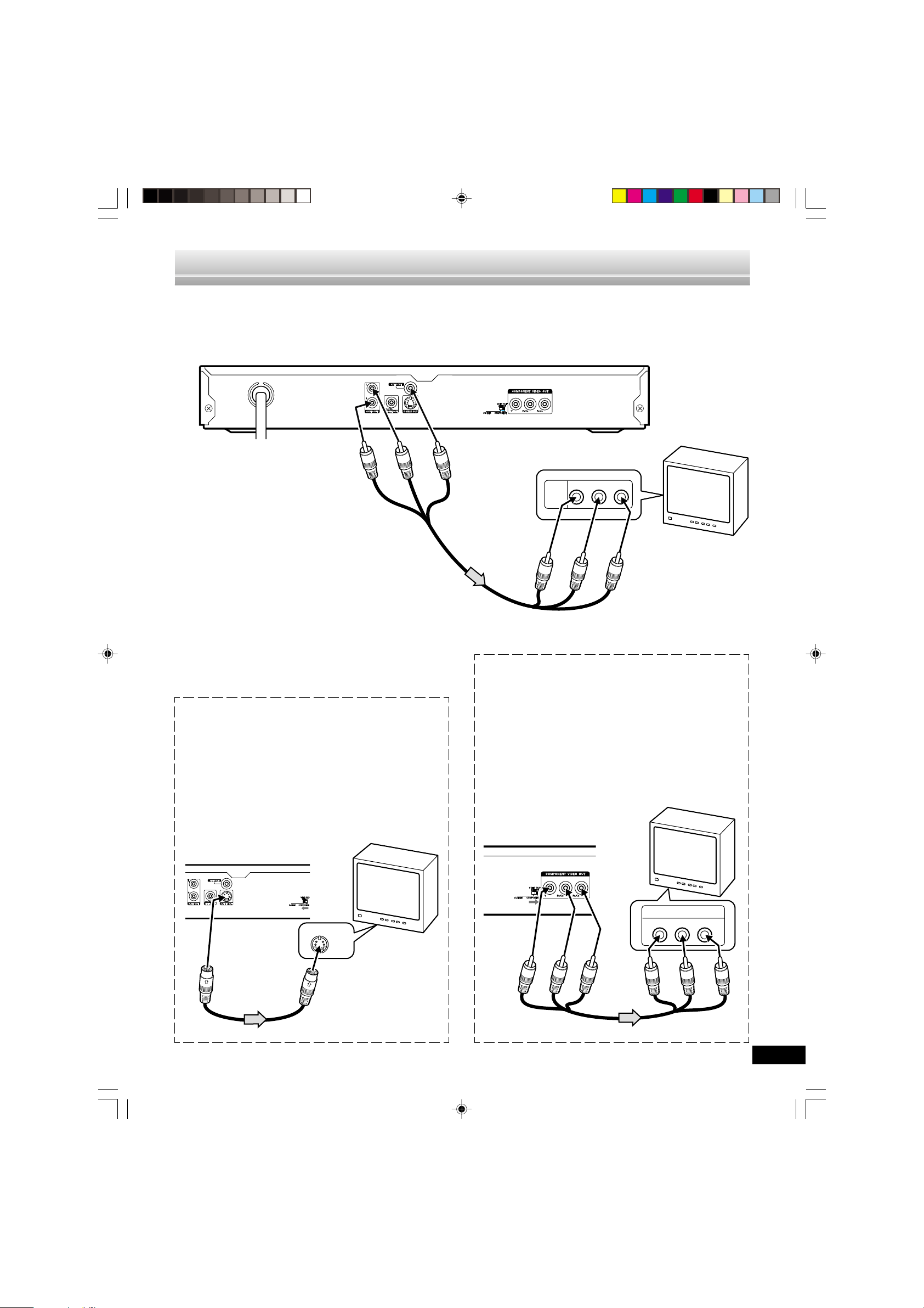
Connecting to a Conventional TV (Example 1)
Connect the DVD video player to your TV.
DVD video player
To AC 120V, 60Hz
(Red) R
(White) L
To AUDIO OUT jacks
Audio/Video cable (supplied)
Notes:
• Please refer to your TV instruction manual.
• When you connect the DVD video player to your TV, be sure
to turn off the power and disconnect both units from the wall
outlet until all the connections have been made.
• If your TV has one audio input jack, connect the AUDIO OUT
jacks of the DVD video player to a Y-cable adaptor (not
supplied), then connect it to the TV Audio input. Please consult your local audio/video dealer.
• Do not connect the DVD video player to a VCR directly . The
playback picture will be distorted because DVD video discs
are copy protected.
Using the S-VIDEO jack
Note:
Please follow the steps before turn on the power.
1. If your TV has the S-video input jack, connect the DVD
video player with the S-video cable (not supplied). (The
VIDEO OUT jack connection is not necessary.)
You can enjoy clearer picture playback.
2. Set the VIDEO OUT SELECT switch to the S-VIDEO
position.
3. You also need to connect the left and right audio cables
(not supplied) to the AUDIO OUT jacks of DVD video player
and the Audio input jacks of the TV.
TV with Audio/Video input jacks
To VIDEO OUT jack
(Yellow)
AUDIO
R-AUDIO-L VIDEO
VIDEO
INPUT
1
To audio input jacks
(Red) R
(White) L
To video input jack
(Yellow)
Using the COMPONENT VIDEO OUT jacks
Note:
Please follow the steps before turn on the power.
1. If your TV has the component video input jacks, connect
the DVD video player to these jacks. (The VIDEO OUT or
S-VIDEO OUT jack connection is not necessary.)
You can enjoy high quality picture playback.
2. Set the VIDEO OUT SELECT switch to the COMPONENT
position.
3. You also need to connect the left and right audio cables
(not supplied) to the AUDIO OUT jacks of DVD video player
and the Audio input jacks of the TV.
4. Set the DVD video player to
the INTERLACE position.
See page E15.
TV
DVD video player
T o S-VIDEO
OUT jack
*Please consult your local audio/video dealer.
DVD-SL33/CA(English) 13/06/2003, 10:069
TV
S-VIDEO IN 1
T o S-video input jack
*S-video cable
(not supplied)
-E8-
Blue
Green
Red
Green
Blue
*Component video cable (not supplied)
Red
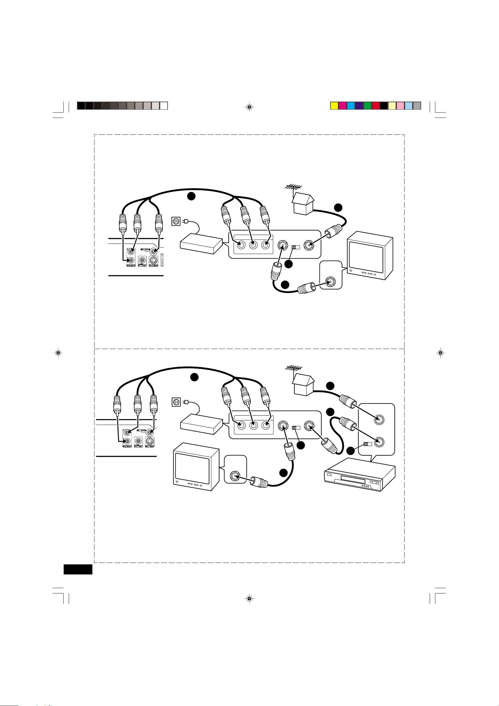
Using RF Modulator
If your TV does not have a Video input jack and has an antenna
terminal only, please purchase the *RF Modulator (not supplied).
(*Please consult your audio/video dealer.)
Example: DVD video player, TV and RF Modulator connections
Audio/Video cable (supplied)
T o AUDIO
OUT jacks
3
T o AC 120V ,
60Hz
To audio input
jacks
1
(Red) R
(White) L
To video input
jack (Yellow)
(Red) R
A/V INPUT JACKS
R-AUDIO-LVIDEO
RF Modulator
To VIDEO OUT jack (Yellow)
DVD video player
1. Connect the antenna cable (not supplied) to the ANT. IN
terminal of the RF Modulator.
2. Connect the 75-ohm coaxial cable (not supplied) between
the TO TV terminal of the RF Modulator and the VHF/UHF
ANTENNA IN terminal of the TV.
3. Connect the Audio/Video cable (supplied) between the AUDIO OUT and VIDEO OUT jacks of the DVD video player
and the AUDIO INPUT and VIDEO INPUT jacks of the RF
Modulator.
Example: DVD video player, VCR, TV and RF Modulator connections
Audio/Video cable (supplied)
T o AUDIO
OUT jacks
4
To audio input
To AC 120V ,
60Hz
To video input
(Red) R
(White) L
jack (Yellow)
A/V INPUT JACKS
R-AUDIO-LVIDEO
RF Modulator
To VIDEO OUT jack (Yellow)
DVD video player
TV
VHF/UHF
ANTENNA
IN
(White) L
TO TV ANT. IN
CHANNEL
34
4
VHF/UHF
ANTENNA
IN
TV
2
4. Turn on the TV, and set the channel number (CHANNEL3
or CHANNEL4) on both TV and RF Modulator, whichever
is not used for regular broadcast in your area.
Note:
For more details, please refer to the instruction manual of the
RF Modulator.
jacks
1
(Red) R
(White) L
TO TV ANT.IN
CHANNEL
34
5
VHF/UHF
2
5
FROM ANT.
34
CHANNEL
IN
TO TV
OUT
3
1. Connect the antenna cable (not supplied) to the VHF/UHF
FROM ANT IN terminal of the VCR.
2. Connect the 75-ohm coaxial cable (not supplied) between
the TO TV OUT terminal of the VCR and the ANT. IN terminal of the RF Modulator.
3. Connect the 75-ohm coaxial cable (not supplied) between
the TO TV terminal of the RF Modulator and the VHF/UHF
ANTENNA IN terminal of the TV.
DVD-SL33/CA(English) 13/06/2003, 10:0610
VCR
4. Connect the Audio/Video cable (supplied) between the AUDIO OUT and VIDEO OUT jacks of the DVD video player
and the AUDIO INPUT and VIDEO INPUT jacks of the RF
Modulator.
5. Turn on the TV, and set the channel number (CHANNEL3
or CHANNEL4) on all TV, VCR and RF Modulator, whichever is not used for regular broadcasts in your area.
Note:
For more details, please refer to the instruction manual of the
RF Modulator.
-E9-
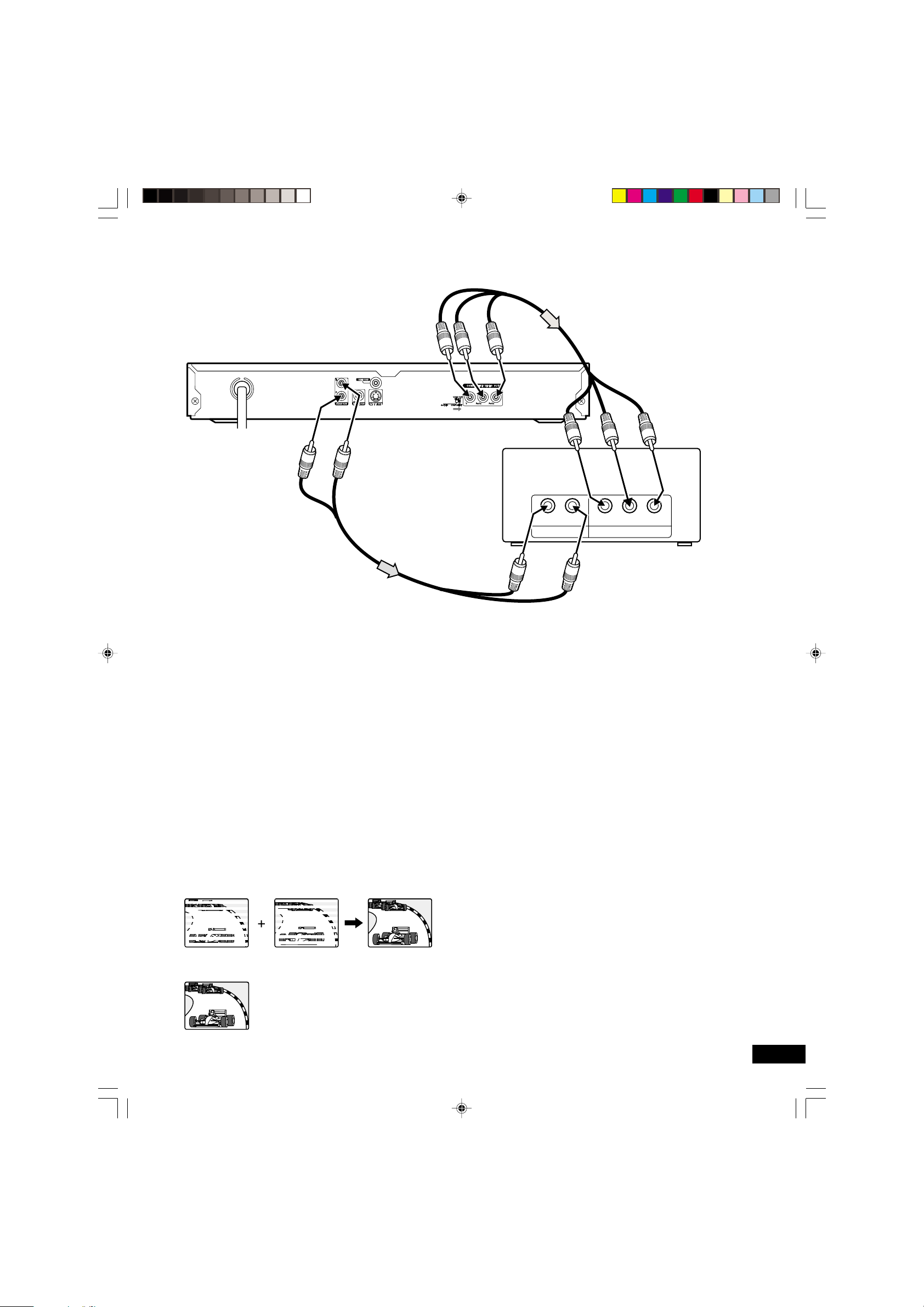
Connecting to a TV with Progressive-scan Capability (Example 2)
Your TV must be capable of handing progressive scanning and have component video input capability.
DVD video player
To AC 120V, 60Hz
*Audio cable (not supplied)
To COMPENENT VIDEO
OUT jacks
To AUDIO OUT jacks
(Red) R
(White) L
Green
Blue
To audio
input jacks
*Component video cable (not supplied)
Red
To COMPONENT
VIDEO INPUT jacks
Green
RL P
COMPONENT VIDEO INPUTAUDIO INPUT
Blue
YP
B
Red
R
TV with progressive-scan
capability
(Red) R
(White) L
*Please consult your local audio/video dealer.
1. Connect the DVD video player to the component video input
jacks of the TV. (The VIDEO OUT or S-VIDEO OUT jack
connection is not necessary.)
2. Set the VIDEO OUT SELECT switch to the COMPONENT
positon.
3. You also need to connect the left and right audio cables (not
supplied) to the AUDIO OUT jack of DVD video player and
the Audio input jacks of the TV.
4. Set the DVD video player to the PROGRESSIVE position.
See page E15.
Progressive Scanning
While interlaced scanning produces one frame of video in two
fields, progressive scanning creates one frame in one field.
Conventional interlaced scanning constitutes one second with
30 frames (60 fields), but progressive scanning constitutes it with
60 frames from scratch. Progressive scanning can reproduce
shaper picture with high resolution for still image or other picture
containing long texts or horizontal lines.
This model has compliance with 525p (progressive) system.
Interlaced scanning
Notes:
• Please refer to your TV instruction manual.
• When you connect the DVD video player to your TV, be sure
to turn off the power and disconnect both units from the wall
outlet until all the connections have been made.
• Do not connect the DVD video player to a VCR directly . The
playback picture will be distorted because DVD video discs
are copy protected.
Progressive scanning
DVD-SL33/CA(English) 13/06/2003, 10:0611
-E10-
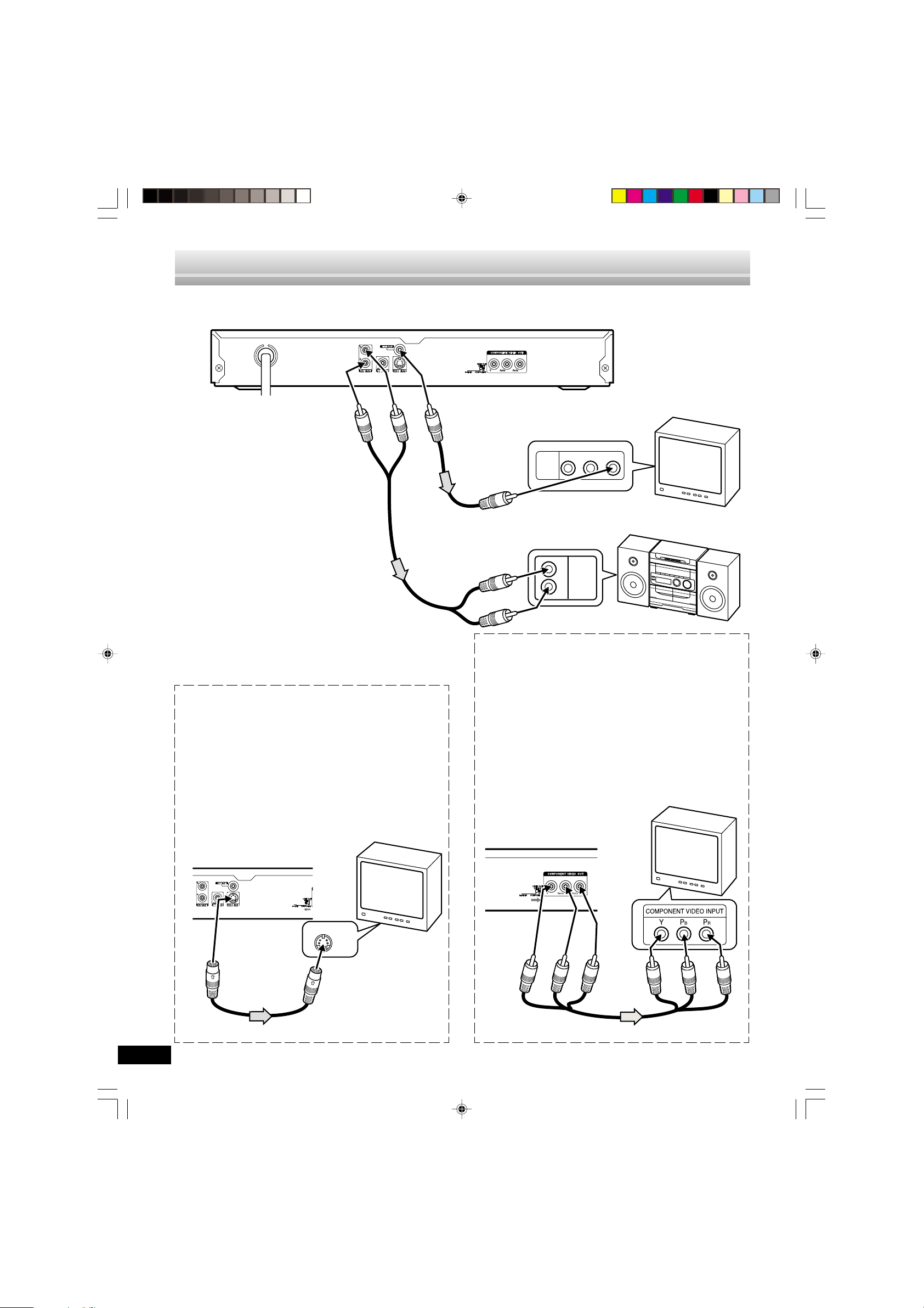
ADDITIONAL CONNECTION EXAMPLES
Connecting to an Audio System and TV (Example 3)
Connect the DVD video player to an Audio System and a TV.
DVD video player
To AC 120V, 60Hz
(Red) R
(White) L
To AUDIO OUT jacks
Notes:
*Audio cable
(not supplied)
• Please refer to the instruction manual of
your Audio System and TV.
• When you connect the DVD video player
to other equipment, be sure to turn off the
power and disconnect all of the equipment
from the wall outlet until all the connections have been made.
• Do not connect the DVD video player to a
VCR directly. The playback picture will be
distorted because DVD video discs are
copy protected.
Using the S-VIDEO jack
Note:
Please follow the steps before turn on the power.
1. If your TV has the S-video input jack, connect the DVD
video player with the S-video cable (not supplied). (The
VIDEO OUT jack connection is not necessary.)
You can enjoy clearer picture playback.
2. Set the VIDEO OUT SELECT switch to the S-VIDEO
position.
3. You also need to connect the left and right audio cables
(not supplied) to the AUDIO OUT jacks of DVD video player
and the Audio input jacks of the Audio System.
To VIDEO OUT jack (Yellow)
To video input (Yellow)
*Video cable
(not supplied)
AUDIO
VIDEO
INPUT
1
To audio input jacks
(White) L
L
R
(Red) R
*Please consult your local audio/video dealer.
Using the COMPONENT VIDEO OUT jacks
Note:
Please follow the steps before turn on the power.
1. If your TV has the component video input jacks, connect
the DVD video player to these jacks. (The VIDEO OUT or
S-VIDEO OUT jack connection is not necessary.)
You can enjoy high quality picture playback.
2. Set the VIDEO OUT SELECT switch to the COMPONENT
position.
3. You also need to connect the left and right cable (not
supplied) to the AUDIO OUT jacks of DVD video player
and the Audio input jacks of the Audio System.
4. Set the DVD video player to the INTERLACE position.
See page E15.
TV with Audio/Video input jacks
R-AUDIO-L VIDEO
AUDIO
INPUT
Audio System
TV
DVD video player
T o S-VIDEO
OUT jack
*Please consult your local audio/video dealer.
DVD-SL33/CA(English) 13/06/2003, 10:0612
TV
S-VIDEO IN 1
To S-video input jack
*S-video cable
(not supplied)
-E11-
Red
Blue
Green
Green
Blue
*Component video cable (not supplied)
Red
 Loading...