

Page 1
FILE NO
SERVICE MANUAL
LED TV
LED-DP32242
PRODUCT CODE No.: 1-130-292-04
CHASSIS NO. :
SSD32TA-00/ P32242-02
REFERENCE No.:SM0945010-02
Page 2

CONTENTS
1. Safety precautions .................................................................................................
2. Alignment instructions ............................................................................................
3. W orking principle analysis of the unit ...................................................................
4. Block diagram ......................................................................................................
5. IC block diagram ..................................................................................................
6. Wiring diagram ...................................................................................................
7. T roubleshooting guide ..........................................................................................
8. Schematic diagram ..............................................................................................
APPENDIX-A: Assembly list
APPENDIX-B: Exploded View
Removing or Installing the Stand
3
5
13
14
17
29
33
37
Page 3

Attention:
please read the following points carefully.
Safety precautions
This service manual is only for service personnel to take reference with. Before
servicing
1. Instructions
Be sure to switch off the power supply before replacing or welding any components or
inserting/plugging
process!):
a) Do not touch here and there by hand at will;
b) Be sure to use anti static electric iron;
c) It’s a must for the welder to wear anti static gloves.
Please refer to the detailed list before replacing components that have special safety requirements.
not change the specs and type at will.
Do
in
connection wire Anti static measures to be taken (throughout the entire production
2. Points for attention in servicing of LCD
2.1 Screens are different from one model to another and therefore not interchangeable. Be sure to
Use the screen of the original model for replacement.
2.2 The operation voltage of LCD screen is
protecting
right
yourself and the machine when testing the system in the course of normal operation or
after the power is switched off. Please do not touch the circuit or the metal part of the module
high voltage. Be
sure to take proper measures in
That is in operation mode. Relevant operation is possible only one minute after the power is switched
off.
2.3 Do not use any adapter that is not identical with the TV set. Otherwise it will cause fire or damage
to the set.
2.4 Never operate the set or do any installation work in bad environment such as wet bathroom,
laundry,
Otherwise
2.5 If any foreign substance such as water, liquid, metal slices or other matters happens to fall into the
module, be sure to cut the power off immediately and do not move anything on the module lest it should
cause fire or electric shock due to contact with the high voltage or short circuit.
2.6 Should there be smoke, abnormal smell or sound from the module, please shut the power off at
once.
power
2.7 Do not pull out or plug in the connection wire when the module is in operation or just after the
power
circuit.
2.8 When operating or installing LCD please don’t subject the LCD components to bending, twisting or
extrusion, collision lest mishap should result.
2.9 As most of the circuitry in LCD TV set is composed of CMOS integrated circuits, it’s necessary to
pay attention to anti statics. Before servicing LCD TV make sure to take anti static measure and
ensure
kitchen, or nearby fire source, heating equipment and devices or exposure to sunlight etc.
bad effect will result.
Likewise, if the screen is not working after the power is on or in the course of operation, the
must be cut off immediately and no more operation is allowed under the same condition.
is
off because in this case relatively high voltage still remains in the capacitor of the driving
Please wait at least one minute before the pulling out or plugging in the connection wire.
full grounding for all the parts that have to be grounded.
2.10 There are lots of connection wires between parts behind the LCD screen. When servicing or
moving
would
If the connection wires, connections or components fixed by the thermo tropic glue need to disengage
when service, please soak the thermo tropic glue into the alcohol and then pull them out in case of
damage.
the set please take care not to touch or scratch them. Once they are damaged the screen
be
unable to work and no way to get it repaired.
3
Page 4
2.11 Special care must be taken in transporting or handling it. Exquisite shock vibration may lead to
breakage
before
2.12 For the storage make sure to put it in a place where the environment can be controlled so as to
prevent
prolonged
place.
of
screen glass or damage to driving circuit. Therefore it must be packed in a strong case
the transportation or handling.
the temperature and humidity from exceeding the limits as specified in the manual. For
storage, it is necessary to house it in an anti-moisture bag and put them altogether in one
The ambient conditions are tabulated as follows:
Temperature
Scope for operation
0
~+ 50
oC
Humidity
2.13
Display of a fixed picture for a long time may result in appearance of picture residue on the
as
screen,
of LCD screen. This phenomenon doesn’t represent failure. This “ghost shadow” may remain
in the picture for a period of time (several minutes). But when operating it please avoid displaying still
picture in high brightness for a long time.
commonly called “ghost shadow”. The extent of the residual picture varies with the maker
Scope for storage
Scope for operation
Scope for storage
-20 ~
+ 60oC
20% ~
5% ~ 90%
90
%
3. Points for attention during installation
3.1 The front panel of LCD screen is of glass. When installing it please make sure to put it in place.
3.2 For service or installation it’s necessary to use specified screw lest it should damage the screen.
3.3 Be sure to take anti dust measures. Any foreign substance that happens to fall down between the
screen and the glass will affect the receiving and viewing effect
3.4 When dismantling or mounting the protective partition plate that is used for anti vibration and
insulation
3.5 Be sure to protect the cabinet from damage or scratch during service, dismantling or mounting.
please take care to keep it in intactness so as to avoid hidden trouble.
4
Page 5
2. Alignment instructions
(1) Test equipment
VG-859 (YPbPr, VGA, HDMI signal generator)
FLUKE 54200(TV signal generator)
CA210 (white balancer)
(2) Power test
Connect main board, power board and IR board according the wiring diagram, connect
the power and press power key (Remote controller or Keypad) button to turn on the TV.
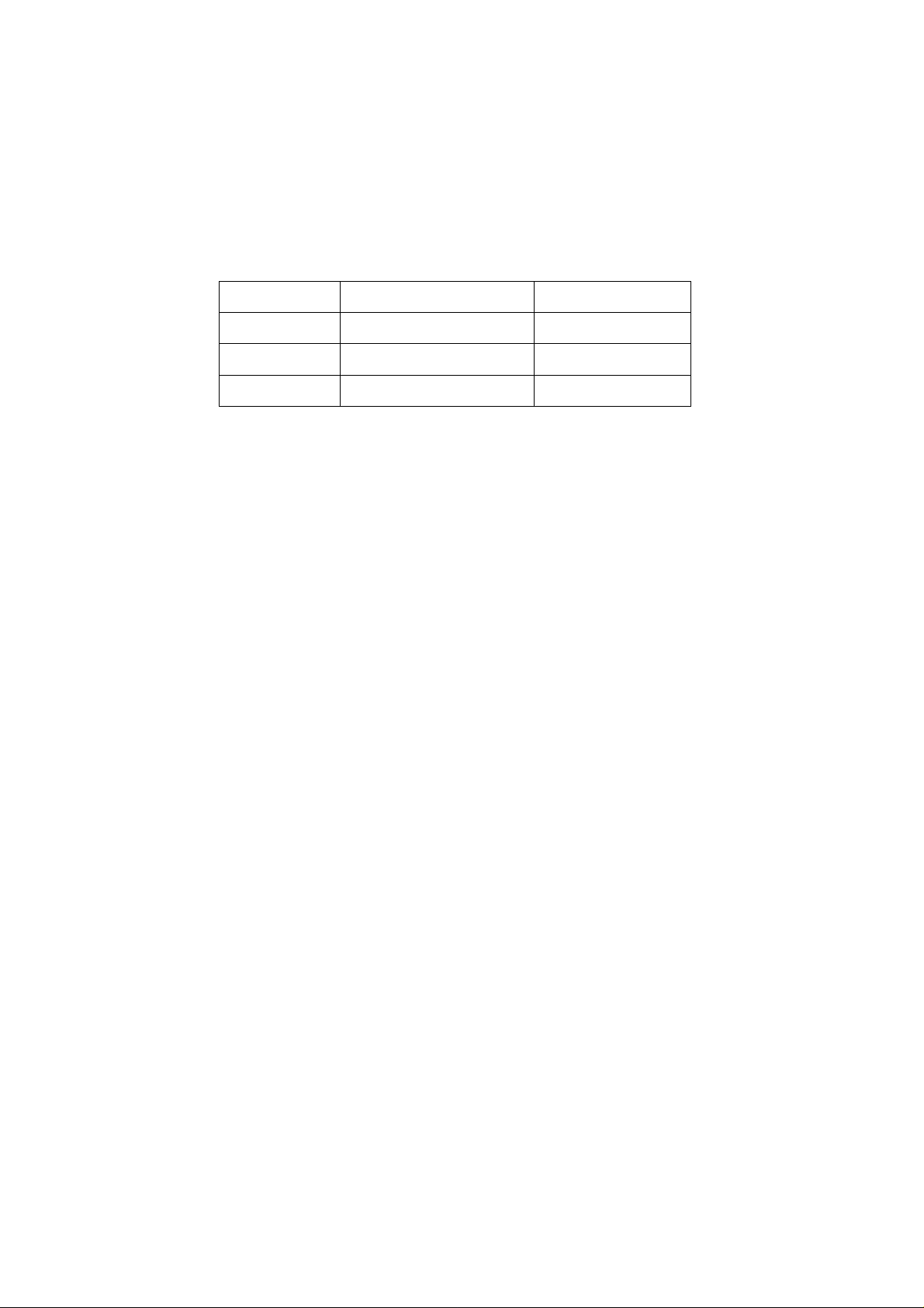
a) Test the pin voltage of P802/power board , the data is shown in table1:
Table1
voltage data of P802
For32”
P802 Pin1,2
Voltage GND 22.8-25.2V
b)
Test the pin voltage of P803/power board, the data is shown in table2:
Pin3,4 Pin5,6,7
GND
Pin8,9 Pin10 Pin11,12
11.6-
12.8V
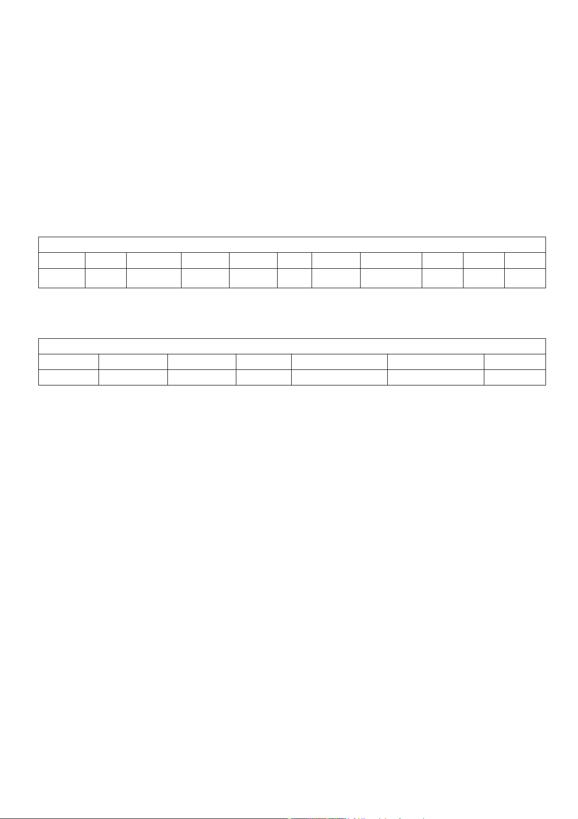
Table2 voltage data of P803
For32”
P803 Pin1,2,3,4,5 Pin6,7,8,9,10
Voltage 22.8-25.2V GND NC 2V-5V 2.5-5V PWM NC
Pin11 Pin12 Pin13 Pin14
NA
4.75-
5.25V
On:2V-5.5V
Off: 0-0.5V
Pin13 Pin14 Pin15 Pin16
<0.6V
2.5-5V
PWM
2-5V
5
Page 6
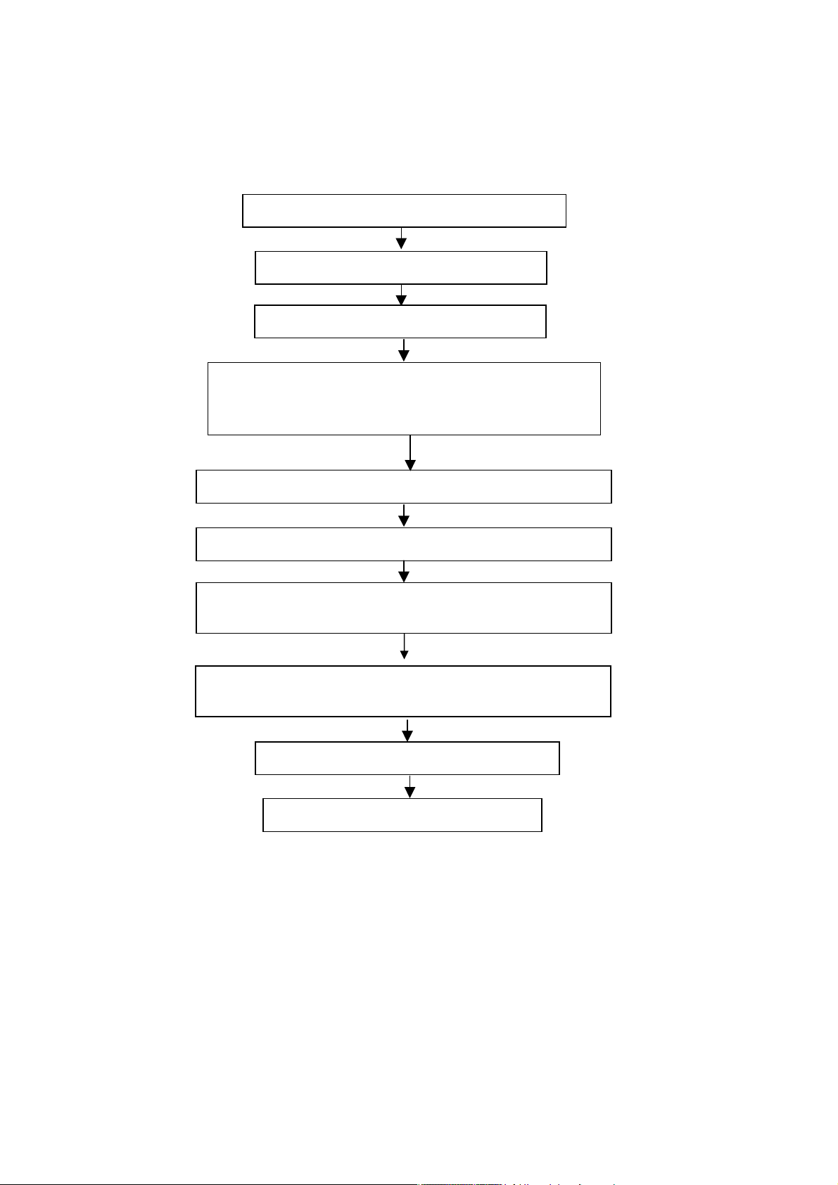
(3) Alignment flow-chart
The alignment flow-chart is shown as fig-1
Connect to the center signal source and check each
Function of TV (station leaking, analog control, etc.)
Check the output of speaker.
Check if DDC, HDCP KEY, FLASH are written
Combined test for general assembly
White balance adjustment
Input AV signal and check the function
Input HD signal and check the function of YPbPr
Input USB signal and check if the display is normal, check
the function (analog control), horizontal/vertical center, etc.
Input HDMI signal and check if the display is normal, check
he function (analog control), horizontal/vertical center, etc.
t
Preset ex-factory
Check the accessories and packing
Fig-1 adjustment flow-chart
6
Page 7
(4) Adjustment instruction
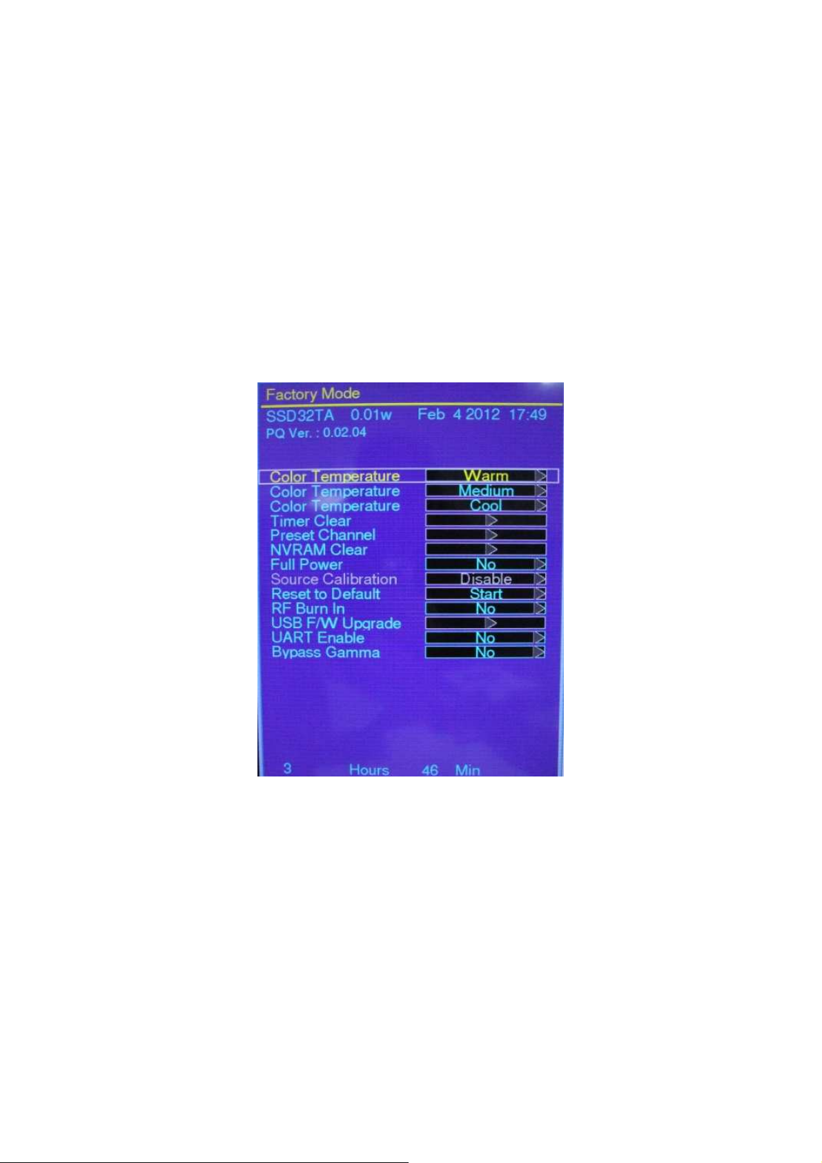
At any input source then press the “←”, “EXIT” and “OK” (Remote control) to enter factory mode
During Factory menu, if “MENU” key is pushed, system will exit factory mode.
(5) Items of Factory menu
When in PC/ Component/ Video (Composite)/ ANT inputs then press the “Left -> Exit -> OK” key of remote control
to enter factory mode..
During Factory menu, if “MENU” or “EXIT” key is pushed, system will exit factory mode.
Press up and down key can move high light item from Color Temperature -> Timer Clear -> Preset Channel>NVRAM Clear-> Full Power -> Source Calibration -> Reset to Default -> RF Burn In -> USB F/W Upgrade ->
UART Enable-> Bypass Gamma.
The Timer Clear, NVRAM Clear and Reset to Default items will have a check dialog “yes or no” to do or not.
Push “Enter” key can select high light item function. (Press left and right can adjust value)
Display panel Burn in Time on the bottom.
Display model name, firmware version and released date on top.
1) Factory Color Temp data edit
This is used for Factory adjusts color temperature. Don't change this value.
2) Timer Clear
Reset the timer which records hours of LCD panel burn in. (Don't clear timer after FW update.)
This item will have a check dialog “yes or no” to do or not.
- Time in factory mode: Time function shall be displayed automatically. Saving the total time of system
power on (LCD turn on), and count the time automatically. The timer is continuous and saved (per 60
minutes) forever, unless it will be reset by doing “Timer Clear”.
3) Preset channel
Load preset channel for production line. (Refer 4.4.4 Preset channel table).
4) NVRAM CLEAR
Initialize program’s default values to NVRAM for following adjustment items accuracy.
In factory mode it is the first and important step to make sure all values are default value and correct
- Reset settings: Gamma table, Channel table (Favorite channel, Channel label etc.), Model table
(H/V Position, Clock, Phase), Source dependent setting (Contrast, Brightness etc.), Common setting
(Volume, Language etc.), Parental Control (Rating, Password etc), Closed Caption.
To avoid a mistake initial process after factory setting is done. This item will have a check dialog “yes
7
Page 8

or no” to do the initial or not.
LINE (pixel)
LINE (pixel)
LINE (pixel)
Notice:
After this item is processed then the DUT needs to be powered off then AC powered off.
5) Full power (For factory test only)
This is for power consumption testing.
To measure the maximum power consumption of TV set, we adjust the value of following items to
maximum.
- Video: Contrast maximum value, Brightness maximum value, Backlight maximum value.
- Audio: Volume maximum value, Bass default value, Treble default value.
Press enter key to turn on Full Power and OSD stay display until press enter key to recover from Full
Power
6) Source Calibration ( without correct machine).
Source Calibration (gain/offset) must be adjusted color by firmware automatic adjustment in PC, and
Component input source.
This item will have a result dialog “OK” or “NG”.
7) Reset to Default
Reset all settings of OSD menu to default value.
- Reset settings: Channel table, Model table (H/V Position, Clock, Phase), Source dependent setting
(Contrast, Brightness etc.), Common setting (Volume, Language etc.), Parental Control (Rating,
Password etc), Closed Caption.
- Please execute Reset to Default once after FW is upgraded.
8) RF Burn In (For factory test only)
Use “snow” pattern for burn in. Selected items are “On” and “Off”.
While turn on burn in mode, firmware will automatically turn off “Auto power off” function.
If there is no power supply suddenly, firmware will re-enter burn in mode automatically when power
supply is back
Pressed the “Power” key, firmware will automatically turn off burn in mode.
Burn in mode: Source is “ANT/Cable" and channel is NTSC channel 3.
9) USB F/W Upgrade
- We don't recommend upgrade FW here. We recommend upgrade FW in normal power on status (not
in factory menu), just plug in USB with correct FW file name. (Refer to item 7)
Upgrade firmware through USB.
10) UART Enable (For factory test only)
Enable to communicate with Auto-Alignment system.
11) Bypass Gamma
For factory test value of gamma.
6) Performance check
(
6-1 TV function
Connect RF to the center signal source, enter Channel menu → auto tuning, check if there are channels be
skipped, check if the picture and speaker are normal.
6-2 AV terminals
Input Video signal, check if the picture and sound are normal.
6-3 YPbPr terminal
Input YUV signal (VG859 signal generator), separately input the YUV signals listed in table4 and check if the
display and sound are normal at any situation (power on, channel switch and format convert, etc.)
Table4 YUV signal format
FREQ PERIOD
SYNC
POLARITY
PIXEL
CLOCK
Display
SYNC
WIDTH
BACK
PORCH
15.734
MODE
LINE(kHz)
FRAME
(Hz)
LINE (pixel)
FIELD
(lines)
1716
LINE
FIELD
Negitive 27
8
(MHz)
FRAME
(lines)
1440
FRAME
(lines)
124
FRAME
(lines)
114
Page 9
59.94Hz 720x480i
3 15
62 60
6 30
40
5 20
44
5 15
44
5 36
96 40
2 25
88
4 23
65
6 29
7 20
6 18
27
3 15
27
62 60
6 30
40
5 20
44
5 15
44
5 36
44
5 36
59.94Hz 720x480P
60Hz 1280x720P
60Hz 1920X1080i
60Hz 1920X1080P
59.94
31,469
59.94
45
60
33.75
60
67.5
60
525
858
525
1650
750
2200
1125
2200
1125
Negitive 480
Negitive 27
720
Negitive 480
Positive 74.25
1280
Positive 720
Positive 74.25
1920
Positive 1080
Positive 148.5
1920
Positive 1080
6-4 HDMI terminal
Input HDMI signal (VG859 signal generator), separately input the signals listed in table6 and check the display and
sound (32 KHz, 44.1 KHz, 48 KHz) at any situation (power on, channel switch and format convert, etc.)
Table6 HDMI signal format
220
148
148
FREQ FREQ PERIOD
MODE
VGA 60Hz 31.469
640x480 59.94
SVGA 60Hz 37.879
800x600 60.317
XGA 60Hz 48.363
1024x768 60.004
WXGA 60Hz 47.776
1280x768 59.87
WXGA 60Hz 47.712
1360x768 60.015
59.94Hz 720x480i 15.734
59.94
LINE(kHz)
FRAME(Hz)
LINE (pixel)
FIELD(lines)
800 Negitive
525 Negitive 480
1056 Positive 40
628 Positive 600
1344 Negitive
806 Negitive 768
1664 Negitive
798 Positive 768
1792 Positive 85.5
795 Positive 768
1716 Negitive
525 Negitive 480
SYNC
POLARITY
LINE
FIELD
PIXEL
CLOCK
(MHz)
25.175 640
79.5
Display
LINE (pixel)
FRAME
(lines)
800
1024
1280
1360
1440
SYNC
WIDTH
LINE (pixel)
FRAME
(lines)
128
136
128
112
124
BACK
PORCH
LINE (pixel)
FRAME
(lines)
160
192
256
114
59.94Hz 720x480P 31.469
59.94
60Hz 1280x720P 45
60
60Hz 1920X1080i 33.75
60
60Hz 1920X1080P 67.5
60
24Hz 1920x1080P 27
24
858 Negitive
525 Negitive 480
1650 Positive 74.25
750 Positive 720
2200 Positive 74.25
1125 Positive 1080
2200 Positive 148.5
1125 Positive 1080
2750 Positive 74.25
1125 Positive 1080
720
1280
1920
1920
1920
9
220
148
148
148
Page 10

6-5 other functions check
a) Check the turn on/turn off timer, sleep timer, picture/sound mode, OSD, stereo and analog TV Teletext, etc.
(7) USB Software updated
(1) Insert the USB with the firmware which the file name is matched with the model name in factory
mode.
(2) If system detect the same firmware file name, USB upgrade message would appear automatically.
(3) Press Left key to select Yes, and then press OK key to start the upgrading.
(4) Upgrading is starting, please wait for the progress finish.
(5) When the progress completed, please follow the instruction to remove USB and restart by AC off
then on.
10
Page 11

3. Working principle analysis of the unit
1.
NTSC
Antenna signal will be send to tuner ENV56U05D8F,
output standard video signal TV-CVBS, and sound SIF signal
signals flow:
th en Tu ne r w il l b e
.
demodulating and
TV-CVBS will send to the master control IC ZR39748 to video decode, de-interlace and scaler, then
output LVDS level drive for panel display.
The sound IF (SIF) will be fed into ZR39748, after demodulating, pre-amplifying, bass adjusting and
volume control, the sound signal
digital amplifier
TAS5707L.
2. Composite/Component signal flow
wi ll be tr an sf or m in to dig it al I2 S si gn a l
and sent to
Composite signal and Component signal will be fed to ZR39748 to perform video decode, deinterlace and scaler, then output LVDS drive level for panel display.
Audio signal from Composite/Component
adjust and volume control, the sound signal will
to digital amplifier
3. HDMI signal flow
TAS5707L
.
terminal
via matched resistance is fed to ZR39748 to bass
b e tr an sf or m int o di gi ta l I2 S si g n a l
and sent
Two HDMI video signals are directly fed to the master control IC ZR39748 to digital decode, image
scale, then output LVDS drive level for panel display. HDMI audio signal via decoder built-in
to bass adjust and volume control, the sound signal will
and sent to digital amplifier
TAS5707L.
b e tr an sf or m in t o di gi ta l I2 S si g n a l
ZR39748
4. USB signal flow
USB signal via USB connector sent to
ZR39 7 48 , th e n output
image scale, then send to LVDS level drive for panel display.
Sound signal of USB signal
volume control, the sound signal will
amplifier
TAS5707L.
ZR3 9 74 8 and it s
R/G/B of 24 bit to back end module to Video decode,
A/D conversion to
YPbPr
output
f or
de-interlace and
vi a
matched resistance
b e tr an sf or m int o di gi ta l I2 S sig na l
a n d
sent to ZR39748 to bass adjust and
and sent to digital
13
Page 12
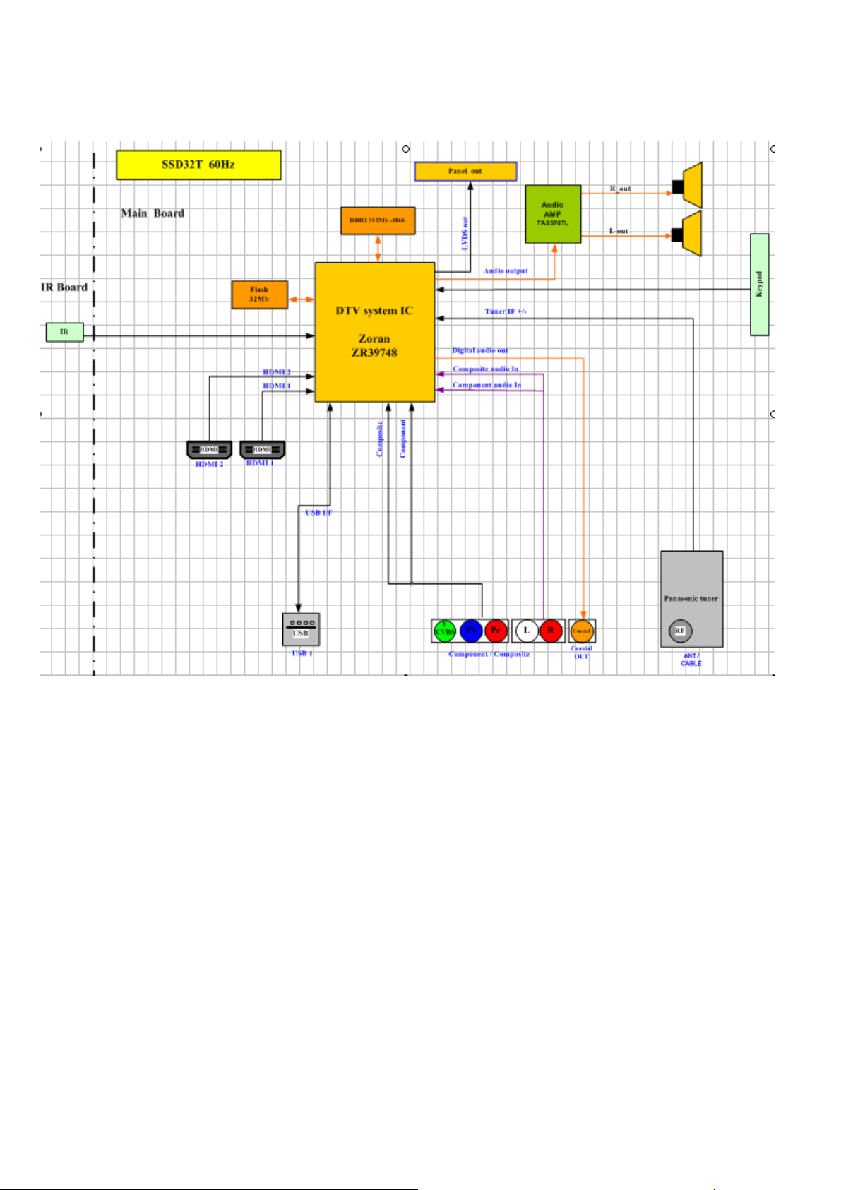
4. SSD32T Block Diagram
4-1 B
lock Diagram
14
Page 13
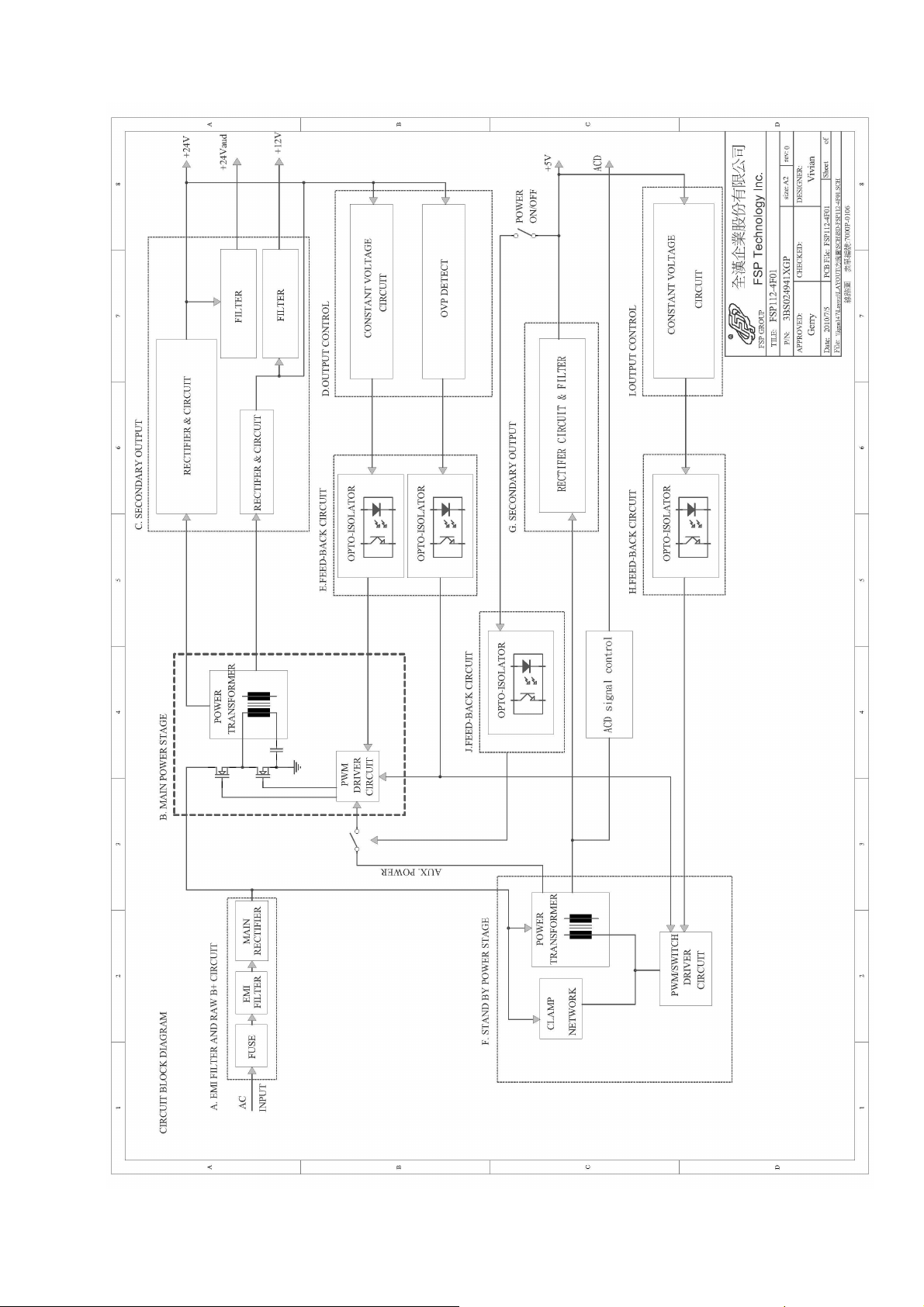
4-2. Power/B block diagram.
a. FSP(1st source) power block diagram.
15
Page 14
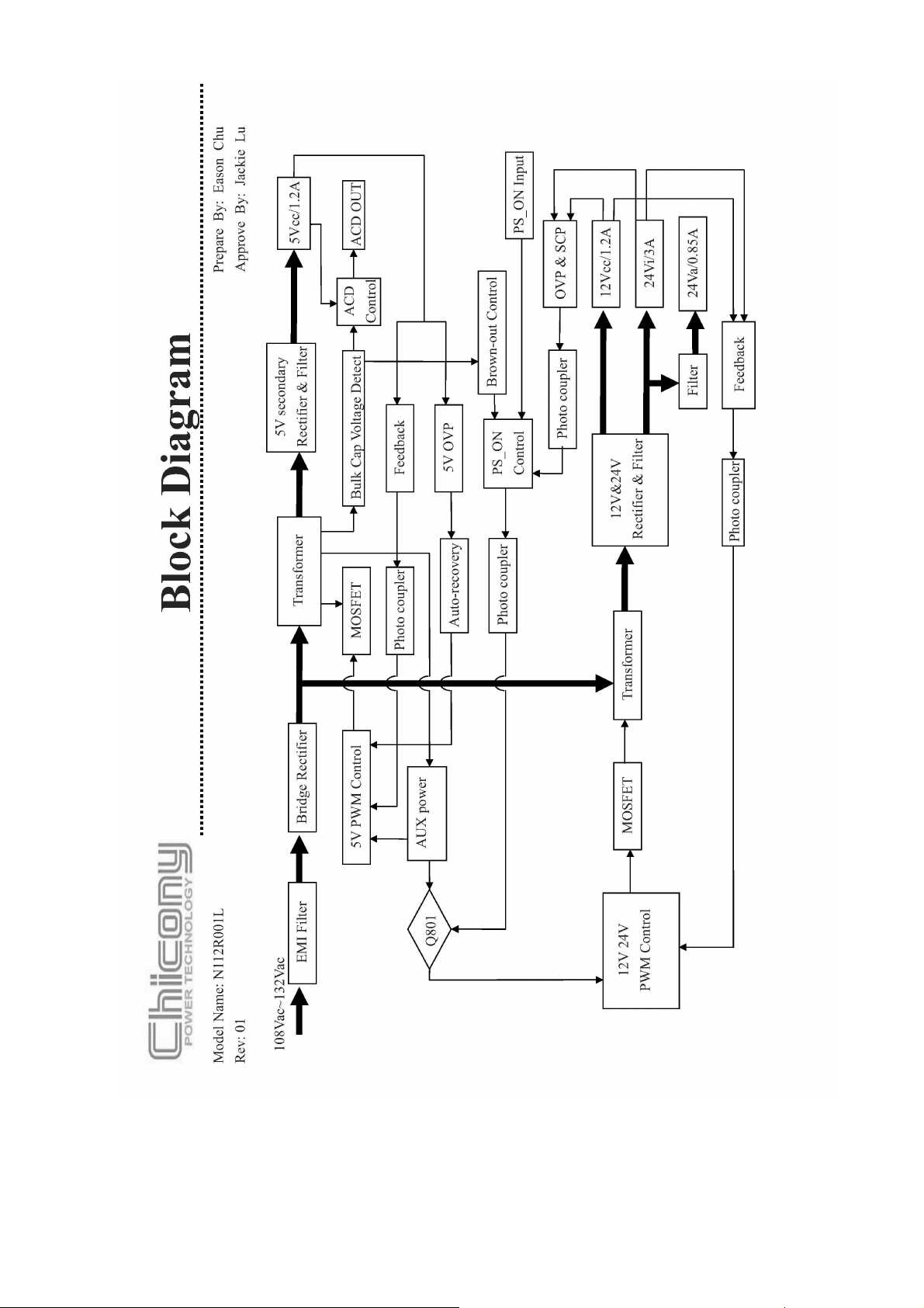
b. Chicony(2nd source) power block diagram.
16
Page 15

5. IC block diagram
1. Zoran ZR748
• Integrated Digital & Analog Demodulator
• 8VSB/QAM-B
• NTSC/BTSC/A2K
• Video Inputs
• Three (3) 1080p HDMI (v1.4a/DC)*
• One (1) 1080p YPbPr
• One (1) VGA, up to WUXGA resolution
• Two (2) CVBS*, One (1) S-Video
udio Inputs
• A
• Five (5) stereo L/R line-level*
• Internal Video/Audio Processing
• NTSC video decoder
• MPEG-2 decoder
• 10-bit video processing
• 1080i motion-adaptive de-interlacer
• ACM-2D color processor
• Graphics blending/overlay
• Audio DSP
• Video Outputs
• Dual-channel LVDS (1080p, up to 10bpp)
miniLVDS & RSDS (6/8bpp, up to 330MHz)
•
• LCD panel timing control signals (TCON)
• Audio Outputs
• One (1) stereo L/R DDX differential
• One (1) stereo L/R single-ended DDX
• Optional up-to-four (4) more single-ended DDX
• Optional up-to-three (3) I2S stereo pairs
• One (1) S/PDIF
• System Processors & Interfaces
• 300MHz system CPU
• TV microcontroller for standby mode
• One (1) USB 2.0
• External SPI Flash Memory: 2-16MByte
• 2-4MB typical for ATSC DTV application
xternal 16-bit DDR2 Required
• E
• DDR2-800 for most design configurations
DDR2-1066 for 1080p with overdrive designs
•
17
Page 16

• 64MByte typical for most designs
• P
ower
• 1.1V core voltage, 1.8V memory I/F, 3.3V I/O
• Two Package Options
• 365-ball BGA, 23x23mm2
• 256-pin LQFP with e-pad, 28x28mm2
(*) Slight variation of support with QFP package
1.1. SupraHD® 748 IC Description
The SupraHD® 748 is a member of the SupraHD® family of DTV system-on-chip (SoC)
eveloped by Zoran. This device is intended to be used in ATSC high-definition digital television
d
implementations. This device includes all of the functionality required to support the television
implementations shown in the following block diagrams.
Figure 2 shows a typical ATSC system implementation using the SupraHD® 748.
Figure 3 shows the detailed block diagram of the SupraHD® 748.
Figure 4 shows the video and audio input/output options of the SupraHD® 748.
1.2. SupraHD® 748 Features
The following sub-sections list the features of the SupraHD® 748 per category. Note that features
unique to the BGA package are indicated with a “(BGA package)” designation while QFP
package features are indicated with “(QFP package)”.
1.2.1. Embedded Processing Unit
igh performance CPU
• H
• Integrated high-performance MIPS® 4KEc™ CPU operating at 300MHz
• 32-bit MIPS32 enhanced architecture
• 8 K instruction cache, 8 K data cache, (2-way set associative)
• Programmable memory management unit
• Multiply/Divide unit
• Power-down mode (triggered by WAIT instruction)
• EJTAG debug support
• Fully production-tested software suite
• ATSC/NTSC DTV application with customizable OSD
V-Chip for analog and digital channels
•
• PSIP parsing for channel map and EPG
• Analog and digital closed-captioning (EIA-608 and EIA-708)
18
Page 17

• Royalty-free Zoran True Fonts for OSD and closed-captioning
•
Transport, video decode (single MP@HL), audio decode (AC-3, MPEG Layer I & II), graphics, and
display drivers
• Drivers for tuner, HDMI and analog inputs
• ThreadX royalty-free RTOS
1.2.2. Video Processing
mage processing
• I
• Up to 10-bit processing
• De-interlacing
- 1080i capable, per-pixel motion adaptive, multiple cadence detection, 8º low-angle interpolation
• Black bar detection
- Horizontal and vertical
• Image quality enhancements
• Noise reduction (up to 1080p)
- Temporal
- Spatial
- Impulse
• MPEG post-processing
- De-blocking
• Adaptive contrast control (histogram-based, fully-programmable)
• Advanced Color Management 2D
• Horizontal luma peaking with coring
• Sharpness control
- Vertical and horizontal LTI
- Horizontal CTI
- Y/C vertical peaking with adaptive coring
•Video scaling and composition
• Horizontal scaler
17-tap FIR, 64-phase FIR
-
- Programmable up scaler [64x]
- Waterglass scaler
- Programmable down scaler [1/32x]
- Non-linear scaler - 3-segment parabola, 17-tap FIR, 64-phase FIR
- Letterbox support
- Pan and Scan support
- 10-bit processing
19
Page 18

• Vertical scaler
-
5-tap FIR, 64-phase FIR
- Programmable up scaler [64x]
- Programmable down scaler [1/32x]
1.2.3. Video Input
• Integrated HDMI link and PHY
• Three physical ports (BGA package)
- One physical port (QFP package)
• Single instance of the PHY
• HDMI v1.4a-compliant
• Supports up to 1080p input resolution
• Standby power CEC monitor
• Supports all DTV resolutions (480i/576i/480p/576p/720p/1080i/1080p)
• Capable of carrying IEC61937 compressed audio (Dolby Digital, etc.)
• Integrated High-bandwidth Digital Content Protection (HDCP) cipher
• Direct capture of video, audio, and control information in distinct memory buffers
ntegrated high definition (HD) capture/video inputs
• I
• Color space conversion
• Downscaling to either 4:2:2 or 4:4:4 output to memory
• One (1) YPbPr input
- Up to 165MHz sample rate (Up to 1080p)
- Sync Modes: sync on green (SOG) or luma (SOY) input, mid-point and sync tip clamping
- SOG or SOY inputs: AC coupled
Low pass filter (500 KHz)
Dynamic range 0.5-2.0V
>1MOhm DC input impedance
- Coast input and support
- Activity/polarity detectors with timing measurement HSYNC present
VSYNC present
SOG/SOY present
• 2nd YPbPr input available using S-Video and SIF lines (BGA package)
One (1) RGB input
•
- Separate HSYNC, VSYNC inputs
TTL level-compatible
- Up to WUXGA (1920x1200x60Hz with reduced blanking)
- Support for 10-bit processing
• Up to 165 MHz input bandwidth
20
Page 19

• Standard definition (SD) video inputs
• Two (2) CVBS inputs (BGA package)
-
One (1) CVBS input (QFP package)
• One (1) S-Video input
• No low-pass filter (LPF) required on SD inputs
1.2.4. Video Output
• Gradient recovery
• Up to 10-bit output for 8-bit video input
verdrive
• O
• Improves LCD response time
• Proprietary Zoran scheme for applying overshoot/undershoot pixel values
• Display processor
• Main output display formats include 1920x1080p, 1680x1050p, 1440x900p, 1366x768p, 1280x768p,
1280x720p and 1024x768p
• Panel frame rate up to 60Hz support for 1920x1080 panel resolution
• Output can support 6, 8 or 10-bit panels
• EIA-608 and EIA-708 closed caption support
• Horizontal and vertical flip support
• Integrated dual-channel LVDS output for direct panel display support
• Supports up to 165MHz (see below for miniLVDS speed)
• 1080p output flat panel support
• 6, 8 and 10-bit panel support
• Programmable PWM backlight control
• Spread spectrum clock generation
- ±6.25% clock modulation
ntegrated Timing Controller (TCON) for direct panel timing control
• I
• Up to 11 user-programmable timing control signals to drive source and gate drivers
• Fail-safe circuit to protect panel from off-spec timing
• miniLVDS dual-channel output with TCON signals activated
- 330MHz single-channel miniLVDS support with TCON signals activated
• RSDS single-channel output with TCON signals activated (BGA package)
1.2.5. Audio Processing and I/O
ive (5) L/R line-level stereo inputs
• F
• Multiplexed into a single stereo ADC
16-bit A/D conversion
-
21
Page 20

- 82dB dynamic range and -75dB THD A/D conversion
-
Supported audio sampling rates from 32 to 96 KHz
• Up to six (6) channels of audio output, on DDX or I2S lines
• Two (2) DDX differential speaker outputs for direct power-stage drive (channels 0-1)
- Or four (4) single-ended DDX for analog output (channels 0-3)
- Or one (1) stereo I2S output (channels 0-1) I2S data aligned in I2S format; Contact Zoran
for left-justified format support
• Two (2) single-ended DDX for line-out (channels 2-3)
- Or two (2) single-ended DDX for analog output (channels 4-5 – only when channels 0-3 are
enabled)
- Or two (2) stereo I2S outputs (channels 2-5 – only when I2S channels 0-1 are enabled)
I2S data aligned in I2S format; Contact Zoran for left-justified format support
2S audio lines (shared with DDX) can be used as inputs
• I
• Six (6) channel I2S input (3 stereo I2S pairs), data aligned in I2S format; Contact Zoran for
left-justified and right-justified formats support
• One (1) S/PDIF output
•Audio decode performed in either/both the audio DSP and CPU
• Audio DSP allows for a significant level of audio post-processing
• L/R downmix for standard stereo digital or line-level output
• Algorithms available for the following:
- Dolby® AC-3 Class A
- MPEG audio Layer 1 (ISO-13818-3)
- “Musicam” MPEG audio Layer 2 (ISO-13818-3)
- MP3 MPEG audio Layer 3 (ISO-13838-3)
- Tone generation
- Post-processing 3D surround & Dialog Clarity (SRS TruSurroundHD™, QSurround)
- Post-processing bass and treble control (Audyssey® ABX)
Post-processing automatic volume control (Audyssey® AVL)
-
- Post-processing 5-band equalizer (Audyssey® AEQ)
• Supports audio and video PTS synchronization
• Stores processed streams in memory for playback using APU
• Audio Processing Unit (APU)
• Single independent integrated APU unit
• Audio playback from unified memory
• Audio select, mix, cross-fade, and attenuate all audio sources
• Supports multiple serial data formats
• Supports sample rates up to 96 KHz
• IEC-958 output of encoded or PCM audio data
22
Page 21

1.2.6. Video Decoders
• M
PEG MP@HL decoder
• Decode of a single HD (MP@HL) stream
• Decodes of ISO-13818-2 MP@ML, MP@HL
• Decode of all ATSC-compliant formats
• Slice-level and frame-level error concealment
• The decoder engine can decode MPEG-compressed bitstreams as defined in the following
specifications:
- ISO/IEC 13818-2, “Information Technology - Generic Coding of Moving Pictures and Associated
Audio Information: Video,” (Up to MP@HL)
- A/53, “ATSC Digital Television Standard,” (Table 3)
- DTVMDB04, “DIRECTV MPEG-2 Video Bitstream Specification for the IRD”
ntegrated NTSC decoder
• I
• 3D adaptive comb filter
- Eliminates dot crawl from vertical or horizontal transitions
- Eliminates dot crawl from single pixel lines
- Eliminates false color from high frequency horizontal luma
- Performs ideal YC separation for still image
- No loss in horizontal or vertical chroma detail
- No loss in horizontal or vertical luma detail
- Performs well both on real video images and on test patterns
aptive horizontal PLL
•Ad
- Automatically adjusts loop bandwidth for signal conditions
- Automatically detects VCR source and enters optimum tracking mode; most decoders require a
“VCR mode” bit to be set to optimally handle VCR signals
- Automatically detects VCR special effects mode and compensates
- Comb filter automatically disabled when VCR source is detected
• Robust sync and DC setup acquisition
- DC setup and sync recovery is very robust even in the presence of noise, ghosting, and unlock
condition
- Automatic switch over to “fine” mode operation once rough lock is acquired
• Chroma edge enhancement
- Improves the horizontal transition of the chroma edge
• VBI decoder
- Performs VBI data capture and data slicing embedded in the video lines (composite, S-Video,
analog RF input)
PEG decoding
• J
23
Page 22

1.2.7. Front-End Demod / Demux
• I
ntegrated 8VSB/QAM-B demodulator
• ATSC 8-VSB demodulation
- Enhanced 8-VSB multi-path performance with wide equalizer coverage
- Superior VSB indoor reception using enhanced equalization and synchronization algorithms,
enabling Brazil and other 0 dB ghost reception
- Adaptive control loops dependent upon channel conditions for fast channel acquisition and
optimal tracking
- Advanced doppler ghost rejection
• QAM-B demodulation
- ANSI/SCTE 07, ITU-T J.83 Annex B 64-/256-QAM, 5.06/5.36 Msymbol/sec rate, respectively
- Support all DI modes up to I=128, J=8
- 84-tap equalization range: 36 FFE and 48 DFE for superior cable micro-reflections rejection
- Enhanced phase noise rejection
- Excellent burst noise and combined distortion rejection
- Exceptional AM noise rejection
- Fast channel auto search based on auto 64-/256-QAM detection and wide carrier acquisition
range
• Advanced system functions
- Accepts 44 MHz from the tuner, eliminating external base-band demodulation
- IF AGC PWM output
- All digital recovery loops
- FEC statistics, receiver status, and channel data such as S/N ratio, equalizer taps, carrier offset,
and more are available
aptive selection of receiver
•Ad
- Adaptive recovery loops based on channel conditions are used to achieve optimum reception for
both high doppler echoes conditions and 0dB conditions
- The synchronization and the equalization algorithms are based on both training signals and blind
data
- It enables better channel tracking – resulting in achieving all A74 requirements
• Fast channel acquisition in 0dB conditions, < 0.5sec.
• Improves immunity to noise for Brazil ensembles over previous Zoran devices
• Improved phase noise rejection in 0dB conditions
• NTSC demodulator
• Fully programmable digital video frequency and group delay equalization including internal digital
Nyquist filter and excellent sound carrier digital rejection (>60dB)
• Digital carrier recovery (AFT) with accurate report to host
• Digital carrier recovery without quadrature distortions
24
Page 23

• Excellent (110%) over modulation at all white signal (100IRE)
•
Digital video IF AGC and optional delayed tuner AGC with programmable take over point
• AM interference rejection
•BTSC/A2 demodulator
• BTSC mono, stereo and SAP DBX decoding for US NTSC TV reception
• A2 mono, stereo and bilingual decoding for Korea NTSC TV reception
S demultiplexer
• T
• Maximum transport bitrate: 80 Mbit/sec
• ISO-13818-1 compliant
• Supports PID filtering - total number of simultaneous PID filters: 32
• ATSC-compliant transport demultiplexer
• Maximum filtered (output) demux bit rate of 80 Mbits/sec
• PCR locking using internal STC counter and VCXO control
• Demodulator inputs
• One (1) differential IF pair for all tuner formats
• One (1) SIF (sound IF) for audio-only formats
1.2.8. Memory Support
• 16-bit DDR2 interface (400MHz or 475 MHz)
• Up to 1.87 GByte/second peak memory throughput
400MHz DDR2 sufficient for WXGA designs
-
- 400MHz DDR2 sufficient for 1080p designs without TCON/overdrive
- 533MHz DDR2 (clocked at 475MHz) sufficient for 1080p designs with TCON/overdrive
• Up to 128 MBytes maximum memory
- Typical 64MByte system implementation for WXGA and 1080p designs
• High performance arbiter with assignable client priorities
• SSTL-18 Class 1 electrical interface
• Serial FLASH
• 40MHz SPI clock
• Up to 16 MBytes maximum memory
• Typical 2-4 MByte system implementation
1.2.9. Integrated TV MicroController
upport for “Sleep” mode operation
• S
• Front panel I/O support (buttons and display)
25
Page 24

• IRR input
• General-purpose 8-bit ADC with 5 multiplexed inputs
• i.e. Voltage monitoring
• S
leep timer
• Watchdog timer
• GPIO interrupt control
• Support for A/V input monitoring
• Monitors the HDMI inputs for activity
ntegrated EDID memory for HDMI inputs and VGA inputs
• I
• 512 bytes memory x 4 input ports
• Support for automatic VGA signal detection and wake-up
• HDMI CEC support
• UART for debug
• Real-time clock support
1.2.10. Graphics Processing
• 32-bit RGB / YCbCr
• 16-bit RGB
• 8-bit indexed with CLUT
• Graphics Block Transfer (BLT)
• Supports copy, bit depth conversion and alpha blending of 8-, 16- and 32-bit pixel maps with 32-bit
utput
o
• Supports Porter-Duff alpha blending formulas
• Alpha destination and alpha compare
• Point, Line, Rectangle, Text and Trapezoid Draw functions
• Rectangle Fill function
•Graphics Unit Scaler (GUS)
• Support scaling and blending of several graphics planes in a single operation
• Can also perform simple BLT operations (BitBlt, stretch BitBlt, trapezoid BitBlt, mirror BitBlt, rotate
BitBlt)
• Color space converter
• Raster Operation (ROP)
1.2.11. System Interfaces
26
Page 25

• Two (2) PWM outputs
• Three (3) 2-signal UARTs
• Maximum baud rate: 115200
•
16550 compatible
• Third UART is allocated to TVuC and shared with main CPU UART
• Two (2) I2C master or slave interfaces
• Maximum bitrate: 400 Kb/s
• Master or slave mode
ne (1) IR receiver, with hardware demodulation
• O
•SPI interface
• Up to 40 MHz clock rate
• Suppports serial FLASH up to 16 MByte
• Two (2) select signals for peripheral support
• Integrated USB interface
• One High Speed USB v2.0 port
1.2.12. Security Features
• Integrated One Time Programmable memory (OTP)
• 8 Kb of One Time Programmable (OTP) secure memory
• Used for secure storage:
- HDCP Key Selection Vectors (KSVs)
- Error Correction (ECC) Checksum and data
• Readable ONLY by specific IROM instructions programmed into the SupraHD® 748
HDMI keys are encrypted with a proprietary Zoran encryption algorithm during the programming
•
process
1.2.13. Misc. IC Information
•25.000 MHz crystal input required to support standard ATSC timing
27
Page 26

2. TEXAS INSTRUMENTS TAS5707L
0-W STEREO DIGITAL AUDIO POWER AMPLIFIER
2
28
Page 27

I. BLOCK
6. SSD32T 32-inch Wiring Diagram
29
Page 28

II. Wiring Connection
1
1
2
2
3
4
3
5
4
6
7
8
9
3
10
11
12
13
14
1
15
2
16
3
SAMSUNG panel
Main board to Panel
SSD32T
DC02L00410I
310 mm
Panel side Main board CN17
IS 100-L30O-C23 LVDS cable A2006WV0-2X20P
VIN RED 1 LVDS_PWR
VIN RED 2 LVDS_PWR
VIN RED 19 LVDS_PWR
VIN RED 20 LVDS_PWR
NC NC
GND NC
GND NC
NC NC
LVDS_SEL YELLOW
NC NC
LVDS_SEL
Main board to Speaker
SSD32T
DC02V03730I
L:330 & R:730 mm
Main board CN3 Speaker
JWT A2001WV2-4P
SPK_OUTL+ BLACK P3 Speaker -
SPK_OUTL- RED P2 Speaker +
SPK_OUTR- WHITE P4 Speaker +
SPK_OUTR+ GREEN P5 Speaker -
Main board to IR board
Color LEFT
Right
SSD32T
DC02V03720I
GND NC
LV0_N YELLOW 14 LVDS_D0O_N
LV0_P WHITE 13 LVDS_D0O_P
GND NC
LV1_N RED 12 LVDS_D1O_N
LV1_P WHITE 11 LVDS_D1O_P
IR board CN1 Main board CN4
JWT A2001WR2-5P
VCC5_0_STB Red 1 VCC5_0_STB
IRR White 2 IRR
GND Black 3 GND
30
330 mm
Color JWT A2001WR2-5P
Page 29

17
GND BLACK 4 GND
3
18
5
19
20
21
22
23
24
25
26
27
28
29
30
LED_R Orange 4 LED_R
LV2_N ORANGE 10 LVDS_D2O_N
LV2_P WHITE 9 LVDS_D2O_P
GND BLACK 17 GND
LVCLK_N BROWN 16 LVDS_CO_N
LVCLK_P WHITE 15 LVDS_CO_N
GND BLACK 18 GND
LV3_N BLACK 8 LVDS_D3O_N
LV3_P WHITE 7 LVDS_D3O_P
GND NC
NC NC
NC NC
NC NC
GND NC
Light Sensor NC
31
Page 30

Power/B to Main board
SSD32T
DC02P01590I
370 mm
Power/B P802 Main board CN2
A2008H00-16P Color A2001H02-16P
1 GND Black 1 GND
2 GND Brown 2 GND
3 24Va -- 3 Audio power
4 24Va Orange 4 Audio power
5 GND Yellow 5 GND
6 GND Green 6 GND
7 GND Blue 7 GND
8 12Vcc -- 8 12V panel
9 12Vcc Gray 9 12V panel
10 NC -- 10 5V standby
Power/B to Panel Inverter/B
SSD32T
DC02P01250I
400 mm
Power/B P803 Panel BL
A2008H00-14P Color A2001H02-14P
1 24Vcc Black 1 24Vcc
2 24Vcc -- 2 24Vcc
3 24Vcc Red 3 24Vcc
4 24Vcc -- 4 24Vcc
5 24Vcc -- 5 24Vcc
6 GND Green 6 GND
7 GND -- 7 GND
8 GND Purple 8 GND
9 GND -- 9 GND
10 GND -- 10 GND
11 5Vcc Black 11 5V standby
12 5Vcc -- 16 BL_ERROR
13 PW_ON Red 12 PW_EN
14 ACD Orange 13 PG
15 DIM Yellow 15 BL_DIM
16 BL_ON Green 14 BL_EN
11 NC -- 11 Error Out
12 BL_ON Brown 12 ENA
13 DIM Black 14 Ext PWM
14 NC -- 13 DIM
32
Page 31

7. Trouble shooting
1. Fault clearance
Before calling your dealer or service center for assistance, check the matters below once again.
(1) Make sure you have connected LCD TV to your equipment as described in the section
“ CONNECTING LCD TV”.
(2) Check cable connection. Verify that all external equipment and power cord are properly
connected.
(3) Verify that all power is switched on.
(4) If LCD TV still dose not produce an image, re-start the external equipment.
(5) If the image still dose not appear, unplug LCD TV from the external equipment and check the
external equipment. The problem may be with your graphics controller rather than with LCD TV.
(When you reconnect LCD TV, remember to turn the external equipment and TV off before you
power up LCD TV. Power the equipment back on in order of LCD TV and external equipment.)
(6) If the problem still exists, check the following chart.
Problem Try these Solutions
NO POWER
Remote
Control dose
not work
No image
No sound
There are tiny
black points
and/or bright
point on the TV
Abnormal
color of image
Plug this LCD TV into the AC outlet.
Press POWER button on side control or on Remote Control to turn on LCD TV.
Check POWER Indicator. If this indicator blank, this TV has getting trouble.
Check the batteries.
Make sure nothing is between the Remote Receiver and the Remote Control.
Make sure you are not too far from LCD TV when using Remote Control.
Maximum operating range is 5m.
Is direct sunlight or strong artificial light shining on LCD TV‘s Infrared Remote
Receiver? Eliminate the light by closing curtains, pointing the light in a different
direction, etc.
Check the connection between the external equipment and LCD TV.
When turning LCD TV on, it takes a few seconds to display the image.
Check the system that you select is corresponding with the external equipment
or the video equipment.
Make sure the temperature is not out of the Operating Temperature (0°C ~
50°C).
Turn off power, then turn on again, re-start LCD TV.
Check Audio cable connection from Audio input source.
Adjust the Sound System.
Press VOLUME (+) button.
Press MUTE button.
Dark or bright points of light (red, green, or blue) may appear on the screen.
This is a characteristic of the LCD panel, not a malfunction of the LCD TV.
LCD panel is produced with very high accuracy technology. There is 99.99% or
more dot pixel, but there is also 0.01 % or less of dot pixel lack or dot pixel that
is constantly lighted. This is not defect.
Regarding LCD panel characteristic, it may occur picture remain (look like a
mirror) when the screen is changed if it displays same screen for a long time.
Changing the picture or turn-off the power supply may recover.
Stripe pattern (more, interference stripes) may show up on the screen depends
on the reflected picture.
Adjust the value of color.
Select different color system.
33
Page 32

Change to new power board.
Check
Check
OK NG H L
Power
LED no
Change MAIN
Change LED
NG
2. Troubleshooting guide
The flow chart shown below will help you to troubleshoot your Televison set with it doesn’t display
n
ormally. Each procedure offers a simple way to check for system errors. Before starting, ensure
that there is a signal in and that the Televison is turned on.
2-1 Power LED no light
Light
P802
+5V
CN2
Pin10,11
Check
LED
P/N: FSP112-4F01(PK101V1750I) or
N112R001L-CP01(PK101V1780I)
PCB
PCB
34
Page 33

2-2 Has audio but no video out
Check
P8
03
Pin1~5
Change to new power board.
P/
N: FSP112-4F01 (PK101V1750I) or
N112R001L-CP01(PK101V1780I)
2-3 Has video but no audio out step 1
35
Page 34

2-4 Has video but no audio out step 2
Check
R831
Vcc+24V
Change to new power board.
P/N: FSP112-4F01 (PK101V1750I) or
N112R001L-CP01(PK101V1780I)
36
Page 35

8.SCHEMATIC DIAGRAM
ELECTRON-"
Page 36

PCB1
PCB1
5
4
3
2
1
ZR39748 Power Tree (60Hz)
D D
12V AMP_VCC
U13
AX1117AD50A
TO-252
U9
VCC12_0
EMB20P03G
SOP8
VTV-L42612 REV:0
VTV-L42612 REV:0
C C
E1
E1
EMIcover-5.3x2.8mm
EMIcover-5.3x2.8mm
VCC5_0_STB
FW1
FW1
FIRMWARE
FIRMWARE
FW A69
FW A69
B B
Stuffing Options
U10
AX1117AD33A
TO-252
U12
AX3518
SOP8-T5
Q17
SOT-23GDS
APM2301AAC
(TVM_PWR_ON2)
For Tuner
For Panel
VCC3_3_IO
VCC3_3_STB
748 3.3V STB power
VCC5_0
A)
VCC5_Tuner
LVDS_PWR
(1.17V)
VCC1_1_Core
VCC1_1_STB
(1.17V)
748 1.1V STB power
Q12
SOT-23GDS
DMP2160U
(TVM_PWR_ON2)
U14
AX6607
SOT23-5
(TVM_PWR_ON2)
Q14
SOT-23GDS
AP2306CGN
(TVM_PWR_ON2)
U11
AX1008MA
TO-263-3
VCC3_3
AFE_1V1
VCC1_1
VCC1_8
(1.1V)
(1.17V)
DDR power
B)
C)
D)
Note: * - Default setting.
A A
COMPAL OP TOELECTRON ICS CO., LTD
COMPAL OP TOELECTRON ICS CO., LTD
COMPAL OP TOELECTRON ICS CO., LTD
Title
Title
Title
SCHEMATIC,M/B VTV-L42612
SCHEMATIC,M/B VTV-L42612
SCHEMATIC,M/B VTV-L42612
Size Document Number Rev
Size Document Number Rev
Size Document Number Rev
Date: Sheet
Date: Sheet
5
4
3
2
Date: Sheet
XXXXXX
XXXXXX
XXXXXX
of
of
of
2 15Thursday, February 16, 2012
2 15Thursday, February 16, 2012
2 15Thursday, February 16, 2012
1
1
1
1
Page 37

5
4
3
2
1
R134 0/0402R134 0/0402
VCC5_0_STBVCC5_0
R130
R130
4.7K/NC
4.7K/NC
POWER_EN
VCC5_0_STB
BKLT_EN
PG_M UTEP 9,11
C174
D D
C C
C174
3.3K/NC
100pF/25V/0402
100pF/25V/0402
3.3K/NC
32"-55" Panel Power -> 12V
24" Panel Power -> 5V
LCD_POWER_ONP10
60HZ from main chip
120HZ from MEMC chip
2011/06/09
1N4148/NCD21N4148/NC
R166
R166
VCC12_0
VCC5_0_STB
VCC5_0_STB
R131
R131
D2
22K/NC
22K/NC
R174
R174
2.2K
2.2K
Q7
Q7
PDTC114ET/NC
PDTC114ET/NC
10K
10K
10K
10K
E C
Switching BLKT_EN & BL_CNTRL
to fit power define.
2011/11/01
FB21
FB21
PWBEAD/ 30/ 6A/1206
PWBEAD/ 30/ 6A/1206
FB34
FB34
PWBEAD/ 30/6A/1206/NC
PWBEAD/ 30/6A/1206/NC
KHB0805W121SA_6A
KHB0805W121SA_6A
FB25
FB25
C189
C189
10uF/10V/0805
10uF/10V/0805
(24V)
AMP_VCC
R132
R132
2.2K/NC
2.2K/NC
C38
C38
SE100uF/35V
SE100uF/35V R142
VCC12_0
R137 0R137 0
R53 10K/0402R53 10K/ 0402
R139
R139
3.3K/1%
3.3K/1%
VCC5_0_STB
R55 0/1206/NCR55 0/ 1206/NC
C172
C172
10uF/16V/0805
10uF/16V/0805
R138 47K/ 1%R138 47K/ 1%
C176
C176
100pF/25V/0402
100pF/25V/0402
U10
U10
AX1117AD33A
AX1117AD33A
panel_power
B
BL_ERRP11
VIN3VOUT
C190
C190
0.1uF/10V/ 0402
0.1uF/10V/ 0402
ADJ / GND
1
C173
C173
1uF/50V/0805/ NC
1uF/50V/0805/ NC
2
249/1%/NC
249/1%/NC
R1650R165
BKLT_EN
BL_CNTRL
C508
C508
1nF/25V/0402
1nF/25V/0402
C177
C177
10uF/10V/0805
10uF/10V/0805
R161
R161
1 2
0
1 2
(12V PANEL)
(5V STANDBY)
POWER_EN
R135
R135
47K/1%
47K/1%
C
B
E
10uF/10V/0805
10uF/10V/0805
PG
Q8
LMBT3904LQ8LMBT3904L
C191
C191
DMP2160U/NC
DMP2160U/NC
CN2
CN2
1
2
3
4
5
6
7
8
9
10
11
12
13
14
15
16
AMA PH-16A-J0
AMA PH-16A-J0
C509
C509
1nF/25V/0402
1nF/25V/0402
POWER INTERFACE
G
DS
Q5
Q5
U9
1
8
S1
D4
2
7
S2
D3
3
6
S3
D2
5
G4D1
EMB20P03GU9EMB20P03G
FB26
FB26
KHB0805W121SA_6A
KHB0805W121SA_6A
C192
C192
PVM330uF/6V/ NC
PVM330uF/6V/ NC
BL_CP11
FB22
FB22
PWBEAD/ 30/ 6A/1206
PWBEAD/ 30/ 6A/1206
R133
R133
1K/1206
1K/1206
VCC3_3_STBVCC3_3_IO
C188
C188
0.1uF/10V/ 0402
0.1uF/10V/ 0402
VCC3_3
LVDS_PWR
R41
R41
10K/1%
10K/1%
R43
R43
1K/1%
1K/1%
R140
R140
560/NC
R160
R160
2.2K/NC
2.2K/NC
R162 12KR162 12K
R183 12KR183 12K
R185
R185
2.2K/NC
2.2K/NC
560/NC
BKLT_EN
VCC3_3_IO VCC3_3
R159
R159
2.2K
2.2K
C
B
Q13
Q13
LMBT3904L
LMBT3904L
E
R180
R180
2.2K
2.2K
C
Q18
Q18
B
LMBT3904L
LMBT3904L
E
BL_CNTRL
C
Q21
Q21
B
LMBT3904L
LMBT3904L
E
LCD_BL_ONP10
R141 0/0402R141 0/0402
R147
R147
3.3K
3.3K
VCC3_3_STB
TVM_PWR_ ON2P11
TVM_PWR_ ON2P11
Reserving for Panel PWM 150Hz. 2011/11/01
R191
R191
PWM2P11
1K/1%
1K/1%
R142
PWM1P15
1K/1%/NC
1K/1%/NC
C178
C178
0.1uF/10V/ 0402/ NC
0.1uF/10V/ 0402/ NC
Q12
Q12
DMP2160U
DMP2160U
S D
C186
C186
1uF/6.3V/ 0402
1uF/6.3V/ 0402
R164
R164
56K
56K
1uF/6.3V/ 0402
1uF/6.3V/ 0402
R186 120KR186 120K
Place
closer
to U1
G
Q17
Q17
DMP2160U
DMP2160U
DS
C212
C212
G
C443
C443
SE100uF/16V
SE100uF/16V
C223
C223
+
+
SE100uF/16V/ NC
SE100uF/16V/ NC
FB24
FB24
KHB0603N121SA
KHB0603N121SA
FB32
FB32
KHB0603N121SA
KHB0603N121SA
BL_CNTRL
VCC5_0VCC5_0_STB
C187
C187
0.1uF/10V/ 0402
0.1uF/10V/ 0402
C447
C447
0.1uF/10V/ 0402
0.1uF/10V/ 0402
TVM_PWR_ ON1P11
C175
C175
100pF/25V/0402
100pF/25V/0402
Q14
R179
R179
130K/0402
130K/0402
Q14
AP2306CGN
AP2306CGN
D
D
G
G
S
S
C207
C207
1uF/6.3V/ 0402
1uF/6.3V/ 0402
FB30
FB30
KHB0805W121SA_6A
KHB0805W121SA_6A
C205
C205
0.1uF/10V/ 0402
0.1uF/10V/ 0402
VCC5_0_STBVCC3_3_STB VCC1_1_Core VCC1_1
B B
FB28 KHB0805W121SA_6AFB28 KHB0805W121SA_6A
C199
C199
10uF/10V/0805
10uF/10V/0805
DC - DC FROM VCC TO 1.17V(2A)
U12 AX3518ESAU12 AX3518ESA
8
VIN
LX
1
VCC
FB
5
EN
REF
PGND
GND
THEM_PAD
6
3
9
C201
C201
0.1uF/10V/ 0402
0.1uF/10V/ 0402
0.1uF/10V/ 0402
0.1uF/10V/ 0402
R17510R175
10
R169
VCC3_3_STB
C206
C206
R169
2K/0402
2K/0402
0.1uF/10V/ 0402
0.1uF/10V/ 0402
R172
R172
C203
C203
1K/0402
1K/0402
L24 2.2uH/3. 8AL24 2.2uH/3. 8A
7
C198 15pF/50V/0402C198 15pF/50V/0402
4
2
C204
C204
0.1uF/10V/ 0402
0.1uF/10V/ 0402
R170 316K/1%R170 316K/1%
R171 681K/1%R171 681K/1%
(Change tO 1.17V)
FB35
FB35
KHB0805W121SA_6A
KHB0805W121SA_6A
0.1uF/10V/ 0402
0.1uF/10V/ 0402
C202
C202
22uF/6.3V/ 0805
22uF/6.3V/ 0805
VCC1_1_STBVCC5_0_STB VCC1_1_Core
C507
C507
TVM_PWR_ ON2P11
R176 12KR176 12K
R173
R173
4.7K
4.7K
C
Q15
Q15
B
LMBT3904L
LMBT3904L
E
Vout=0.8Vx (1+R170/R171)
U11
C195
C195
0.1uF/10V/ 0402
0.1uF/10V/ 0402
U11
AX1008MA
AX1008MA
VIN3VOUT
GND/ADJ
2
4
VOUT
1
R167
R167
249/1%
249/1%
1 2
R168
R168
110/1%
110/1%
1 2
2
VCC5_0
FB27
FB27
KHB0603N121SA
KHB0603N121SA
U14
A A
VCC3_3_STB
FB33
FB33
KHB0603N121SA
KHB0603N121SA
10uF/10V/0805
10uF/10V/0805
5
TVM_PWR_ ON2P11
C216
C216
R181 10K/1%R181 10K/1%
C217
C217
0.1uF/10V/ 0402
0.1uF/10V/ 0402
R182
R182
100K/1%
100K/1%
3
1
U14
AX6607BA
AX6607BA
/SHDN
IN
5
OUT
4
R184
SET
GND
2
R184
56K/1%
56K/1%
R187
R187
150K/1%
150K/1%
4
1A
C218
C218
0.1uF/10V/ 0402
0.1uF/10V/ 0402
AFE_1V1
C215
C215
10uF/10V/0805
10uF/10V/0805
C194
C194
SE100uF/16V
SE100uF/16V
VO=1.25Vx(1+R2/R1)+IadjxR2
3
C197
C197
0.1uF/10V/ 0402
0.1uF/10V/ 0402
VCC1_8
C200
C200
10uF/10V/0805
10uF/10V/0805
COMPAL OPTOELECTRONICS CO., LTD
COMPAL OPTOELECTRONICS CO., LTD
COMPAL OPTOELECTRONICS CO., LTD
Title
Title
Title
SCHEMATIC,M/B VTV-L42612
SCHEMATIC,M/B VTV-L42612
SCHEMATIC,M/B VTV-L42612
Size Document Number Rev
Size Document Number Rev
Size Document Number Rev
Date: Sheet
Date: Sheet
Date: Sheet
XXXXXX
XXXXXX
XXXXXX
1
of
of
of
3 15Tuesday, January 17, 2012
3 15Tuesday, January 17, 2012
3 15Tuesday, January 17, 2012
1
1
1
Page 38

5
4
3
2
1
R10 1K/1%/ 0402R10 1K/1%/ 0402
R19
R19
C22
C22
R11 4.7K/0402R11 4.7K/0402
VCC3_3
VCC3_3
R12 1K/1%/0402R12 1K/1%/0402
R13 1K/1%/0402R13 1K/1%/0402
R20
R20
4.7K/0402/NC
4.7K/0402/NC
SPI_WEN
R23
R23
4.7K/0402
4.7K/0402
VCC5_0_USB
USB2_DN
USB2_DP
C21
C21
0.1uF/10V/0402
0.1uF/10V/0402
EJTAG I/F
VCC3_3
J1
J1
1 2
R14 4.7K/0402R14 4.7K/0402
3 4
5 6
7 8
9 10
11 12
13 14
HDR_2X7_2040
HDR_2X7_2040
SPI FLASH
U3
U3
MX25L3206EM2I-12G
MX25L3206EM2I-12G
SPI FLASH
5
2
6
1
3
7
SPI FLASH
32M bit
32M bit
DIO
DO
CLK
CS
WP
HOLD
VCC3_3
8
Vcc
C17
C17
0.1uF/10V/0402
0.1uF/10V/0402
4
GND
For FHD
USB
1
2
3
6
4 5
USB_RA_NK
USB_RA_NK
IO1
IO1
Note: Control differential
impedance at 90 ohms +/- 15%
I2C_1_SCL
I2C_1_SDA
I2C_0_SCL
I2C_0_SDA
R9 4.7K/0402R9 4.7K/0402
R15 4.7K/0402R15 4.7K/0402
R16 4.7K/0402R16 4.7K/0402
R17 4.7K/0402R17 4.7K/0402
MCU RESET
VCC3_3_STB
Reset
Switch
VCC_5V_STB change to VCC5_0
VCC3_3
VCC3_3
VCC3_3_STB
U4
U4
POR
POR
3
VCC
/RESET
1
GND
AX6901ERA
AX6901ERA
SW1
SW1
1 4
2 3
SW PUSH/5P/180D/NC
SW PUSH/5P/180D/NC
R21
R21
3.3K/0402
3.3K/0402
R29
C18
C18
10nF/16V/0402
10nF/16V/0402
R29
1K/0402
1K/0402
LMBT3904L
LMBT3904L
C
Q10
Q10
E
2
Adding 5 secs power on function. 2011/11/08
USB Power Control
VCC5_0_USB
VCC5_0
FB1
FB1
KHB0603N121SA
KHB0603N121SA
F1
F1
1206L075THYR
1206L075THYR
USB POWER
RESETN
E
C
B
R36
R36
100K/0402
100K/0402
VCC3_3_STB
C30
C30
10uF/10V/0805
10uF/10V/0805
R37
R37
160K/1%/0402
160K/1%/0402
VCC1_1_STB
Q11
Q11
LMBT3906L
LMBT3906L
R31
R31
B
3.3K/0402
3.3K/0402
RESETN P11
FP_GPIO P11
For Development
U1B
D D
C C
B B
A A
U1B
EJTAG
EJTAG
UART
UART
I2C
I2C
SPI
SPI
25M
25M
USB2.0
USB2.0
ZR39748_BGA_A3
ZR39748_BGA_A3
SIO I/F
SIO I/F
TDI/EJTDI/SNDBUS[20]
TDO/EJTDO/SNDBU S[16]
TMS/EJTMS/SNDBUS[15]
TCK/EJTCK/SNDBUS[21]
UART 1_TX/GPIO_S[2]
UART1_RX/GPIO_S[3]
I2C1_C/GPIO_S[4]
I2C1_D/GPIO_S[5]
SPI_DO/GPIO_S[13]
SPI_DI/GPIO_S[7]
SPI_CLK/GPIO_S[14]
SPI_SEL0/GPIO_S[15]
SIP_SEL1/GPIO_S[11]
SPI_HOLD/GPIO_S[12]
CLKOUT _25M
CLKIN_25M
USB2_DN
USB2_DP
USB2_REXT
USB_ATEST
I2C0_C
I2C0_D
D19
D18
C18
D20
F20
E20
F4
F3
A21
A22
C22
B22
B21
C21
Y21
C20
R22 0/0402/NCR22 0/0402/NC
A8
B8
W21
W22
T18
V19
EJTDI
EJTDO
EJTMS
EJTCK
TP3TP3
USB2_REXT
I2C_0_SCL
I2C_0_SDA
I2C_1_SCL
I2C_1_SDA
Y1
Y1
25MHz/20pF/S/2P
25MHz/20pF/S/2P
C19
C19
33pF/50V/0402
33pF/50V/0402
R25
R25
6.04K/1%/0402
6.04K/1%/0402
RESETN
R24
R24
330/1%/0402
330/1%/0402
C20
C20
30pF/50V/0402
30pF/50V/0402
R18 47/1%/0402R18 47/1%/0402
I2C_0_SCL P14
I2C_0_SDA P14
I2C_1_SCL P6
I2C_1_SDA P6
SPI_WENP10
Crystal Y1
50ppm 0-70C
EZJZ1V80010/NCD3EZJZ1V80010/NC
D3
4.7K/0402
4.7K/0402
SPI_WR
SPI_RD
SPI_CLK
SPI_CS_n
SPI_HOLD
D5
10uF/10V/0805
10uF/10V/0805
EZJZ1V80010/NCD5EZJZ1V80010/NC
COMPAL OPTOELECTRONICS CO., LTD
COMPAL OPTOELECTRONICS CO., LTD
COMPAL OPTOELECTRONICS CO., LTD
Title
Title
Title
SCHEMATIC,M/B VTV-L42612
SCHEMATIC,M/B VTV-L42612
SCHEMATIC,M/B VTV-L42612
Size Document Number Rev
Size Document Number Rev
Size Document Number Rev
Date: Sheet
Date: Sheet
5
4
3
2
Date: Sheet
XXXXXX
XXXXXX
XXXXXX
4 15Thursday, February 16, 2012
4 15Thursday, February 16, 2012
1
4 15Thursday, February 16, 2012
1
1
1
of
of
of
Page 39

5
RUN AS 100 OHM
DSHLD0
TMDSD2-
DSHLD1
TMDSD1-
DSHLD2
TMDSD0-
TMDSC+
CSHLD0
TMDSC-
VCC5
SHLD0
SHLD1
SHLD2
SHLD3
DSHLD0
TMDSD2-
DSHLD1
TMDSD1-
DSHLD2
TMDSD0-
TMDSC+
CSHLD0
TMDSC-
VCC5
SHLD0
SHLD1
SHLD2
SHLD3
DSHLD0
TMDSD2-
DSHLD1
TMDSD1-
DSHLD2
TMDSD0-
TMDSC+
CSHLD0
TMDSC-
VCC5
SHLD0
SHLD1
SHLD2
SHLD3
5
1
2
3
4
5
6
7
8
9
10
11
12
13
CEC
14
NC
15
SCL
16
SDA
17
18
19
HPD
20
21
22
23
1
2
3
4
5
6
7
8
9
10
11
12
13
CEC
14
NC
15
SCL
16
SDA
17
18
19
HPD
20
21
22
23
1
2
3
4
5
6
7
8
9
10
11
12
13
CEC
14
ARC
15
SCL
16
SDA
17
18
19
HPD
20
21
22
23
DIFFERENTIAL PAIRS
HDMI0_D2P
HDMI0_D2N
HDMI0_D1P
HDMI0_D1N
HDMI0_D0P
HDMI0_D0N
HDMI0_CLKN
RUN AS 100 OHM
DIFFERENTIAL PAIRS
HDMI1_D2P
HDMI1_D2N
HDMI1_D1P
HDMI1_D1N
HDMI1_D0P
HDMI1_D0N
HDMI1_CLKP
HDMI1_CLKN
RUN AS 100 OHM
DIFFERENTIAL PAIRS
HDMI2_D2P
HDMI2_D2N
HDMI2_D1P
HDMI2_D1N
HDMI2_D0P
HDMI2_D0N
HDMI2_CLKP
HDMI2_CLKN
HDMI2_ARC
R358 47K/1%R358 47K/1%
R359 47K/1%R359 47K/1%
C370
C370
0.1uF/10V/0402
0.1uF/10V/0402
R372 47K/1%R372 47K/1%
R373 47K/1%R373 47K/1%
C400
C400
0.1uF/10V/0402
0.1uF/10V/0402
R398 47K/1%R398 47K/1%
R396 47K/1%R396 47K/1%
C401
C401
0.1uF/10V/0402
0.1uF/10V/0402
IO4
IO4
TMDSD2+
TMDSD1+
D D
C C
B B
A A
TMDSD0+
DDC_GND
HDMI_CONN_RF
HDMI_CONN_RF
IO3
IO3
TMDSD2+
TMDSD1+
TMDSD0+
DDC_GND
24
SHLD4
25
SHLD5
NIKTTECH/HDMI_SMD_V
NIKTTECH/HDMI_SMD_V
IO2
IO2
TMDSD2+
TMDSD1+
TMDSD0+
DDC_GND
24
SHLD4
25
SHLD5
NIKTTECH/HDMI_SMD_V
NIKTTECH/HDMI_SMD_V
4
HDMI_CEC
HDMI0_DDC_SCL
HDMI0_DDC_SDA
HDMI0_5V
R365
R365
10K/1%
10K/1%
HDMI_CEC
HDMI1_DDC_SCL
HDMI1_DDC_SDA
HDMI1_5V
R375
R375
10K/1%
10K/1%
HDMI_CEC
HDMI2_DDC_SCL
HDMI2_DDC_SDA
HDMI2_5V
R376
R376
10K/1%
10K/1%
4
HDMI0_DDC_SCL P11
HDMI0_DDC_SDA P11
HDMI0_5V P11
R357
R357
1K/1%/NC
1K/1%/NC
R382 1K/1%R382 1K/1%
R361
R361
10K/1%/NC
10K/1%/NC
HDMI1_DDC_SCL P11
HDMI1_DDC_SDA P11
HDMI1_5V P11
R371
R371
1K/1%/NC
1K/1%/NC
R383 1K/1%R383 1K/1%
R374
R374
10K/1%/NC
10K/1%/NC
IEC958_OP7,9
HDMI2_DDC_SCL P11
HDMI2_DDC_SDA P11
HDMI2_5V P11
R397
R397
1K/1%/NC
1K/1%/NC
R394 1K/1%R394 1K/1%
R395
R395
10K/1%/NC
10K/1%/NC
HDMI0_HPD P11
Low speed signals locate
in page11, standby block.
HDMI1_HPD P11
R122 1K/NCR122 1K/NC
1 2
HDMI2_HPD P11
CE
B
12
3
HDMI_CEC_INP11
HDMI2_5V
Q9
Q9
MMBT3904L/NC
MMBT3904L/NC
R99
R99
1 2
30/1%/NC
30/1%/NC
R97
R97
1K/NC
1K/NC
3
VCC3_3_STB
HDMI_CEC_INHDMI0_CLKP
C29
C29
1 2
1uF/6.3V/0402/NC
1uF/6.3V/0402/NC
D7
D7
BAT54
BAT54
1 3
1 3
12
12
R101
R101
750/NC
750/NC
R123
R123
3K/NC
3K/NC
1 2
R124 0/NCR124 0/N C
R399
R399
27K
27K
G
G
HDMI2_ARC
2
HDMI_CEC
D
D
Q23
Q23
2N7002E
2N7002E
S
S
Run as 50 Ohm Single Ended Impedance with 100 Ohm differential pairs
HDMI0_D2P
HDMI0_D2N
HDMI0_D1P
HDMI0_D1N
HDMI0_D0P
HDMI0_D0N
HDMI0_CLKP
HDMI0_CLKN
Y2
Y1
W2
W1
V2
V1
U2
U1
Run as 50 Ohm Single Ended Impedance with 100 Ohm differential pairs
HDMI1_D2P
HDMI1_D2N
HDMI1_D1P
HDMI1_D1N
HDMI1_D0P
HDMI1_D0N
HDMI1_CLKP
HDMI1_CLKN
T2
T1
R2
R1
P2
P1
N2
N1
Run as 50 Ohm Single Ended Impedance with 100 Ohm differential pairs
HDMI2_D2P
HDMI2_D2N
HDMI2_D1P
HDMI2_D1N
HDMI2_D0P
HDMI2_D0N
HDMI2_CLKP
HDMI2_CLKN
COMPAL OPTOELECTRONICS CO., LTD
COMPAL OPTOELECTRONICS CO., LTD
COMPAL OPTOELECTRONICS CO., LTD
Title
Title
Title
SCHEMATIC,M/B VTV-L42612
SCHEMATIC,M/B VTV-L42612
SCHEMATIC,M/B VTV-L42612
Size Document Number Rev
Size Document Number Rev
Size Document Number Rev
Date: Sheet
Date: Sheet
Date: Sheet
2
M2
M1
L2
L1
K2
K1
J2
J1
U1C
U1C
HDMI0 I/F
HDMI0 I/F
HDMI0_D2P
HDMI0_D2N
HDMI0_D1P
HDMI0_D1N
HDMI0_D0P
HDMI0_D0N
HDMI0_CLKP
HDMI0_CLKN
U1D
U1D
HDMI1 I/F
HDMI1 I/F
HDMI1_D2P
HDMI1_D2N
HDMI1_D1P
HDMI1_D1N
HDMI1_D0P
HDMI1_D0N
HDMI1_CLKP
HDMI1_CLKN
U1E
U1E
HDMI2 I/F
HDMI2 I/F
HDMI2_D2P
HDMI2_D2N
HDMI2_D1P
HDMI2_D1N
HDMI2_D0P
HDMI2_D0N
HDMI2_CLKP
HDMI2_CLKN
XXXXXX
XXXXXX
XXXXXX
1
ZR39748_BGA_A3
ZR39748_BGA_A3
ZR39748_BGA_A3
ZR39748_BGA_A3
ZR39748_BGA_A3
ZR39748_BGA_A3
5 15Tuesday, January 17, 2012
5 15Tuesday, January 17, 2012
5 15Tuesday, January 17, 2012
1
1
1
1
of
of
of
Page 40

5
4
3
I2C clock - 100KHz(recommended)
I2C Address 0x32/33(AS open)
2
1
D D
C C
B B
I2C ADDR 0xC2/0xC3
U15
U15
ENV56U05D8F
ENV56U05D8F
RF AGC Monitor
15
Panasonic
ENV56U05D8F
Panasonic
ENV56U05D8F
GND
16
GND
17
GND
18
GND
15A
GND
16A
GND
17A
GND
18A
GND
C28
C28
10uF/16V/0805
10uF/16V/0805
BT Monitor
SDA
IF Monitor
IF AGC
IFD-out1
IFD-out2
VCC12_0
1
NC
2
+B
3
5
NC
6
9
SCL
10
11
12
13
14
C35
C35
0.1uF/50V
0.1uF/50V
C123
C123
C100
C100
10pF/50V
C94 1nF/25V/0402/NCC94 1nF/25V/0402/NC
C120 2.2uF/16V/0805/NCC120 2.2uF/16V/0805/NC
C179 1nF/25V/0402/NCC179 1nF/25V/0402/NC
C102 1nF/25V/0402/NCC102 1nF/25V/0402/NC
TUN_SCL
TUN_SDA
C113 1nF/25V/0402/NCC 113 1nF/25V/0402/NC
R244 0/0402R244 0/0402
R243 0/0402R243 0/0402 C101
U13
U13
AX1117AD50A
AX1117AD50A
VIN3VOUT
ADJ / GND
1
2
10uF/10V/0805
10uF/10V/0805
10pF/50V
close to tuner
IFIF+
C36
C34
C34
C36
0.1uF/10V/0402
0.1uF/10V/0402
330pF/50V/0402
330pF/50V/0402
C184
C184
C124
0.1uF/10V/0402
0.1uF/10V/0402
FB7
FB7
C124
C119
C119
10uF/10V/0805
10uF/10V/0805
L12 MMZ1608S102AL12 MMZ1608S102A
12
C101
1nF/25V/0402
1nF/25V/0402
close to tuner
VCC5_Tuner VCC5_0
KHB0805W121SA_6A/NC
KHB0805W121SA_6A/NC
FB18 BLM21PG300SN1DFB18 BLM21PG300SN1D
10uF/10V/0805
10uF/10V/0805
100pF/25V/0402
100pF/25V/0402
IF_AGCTU_AGC
C107
C107
12
12
C105
C105
1nF/25V/0402
1nF/25V/0402
C40,C41 15pF
C42 68pF
C91,C92 1nF
L14,L29 220nH
L5
C91 1nF/25V/0402C91 1nF/25V/0402
IF-
IF+
C92 1nF/25V/0402C92 1nF/25V/0402
Pansonic
150nH
L14
L14
KVL0805R22J
KVL0805R22J
L29
L29
KVL0805R22J
KVL0805R22J
C209
C209
10pF/50V
10pF/50V
IF_AGC
VCC3_3VCC5_Tuner
R143 10K/1%/0402R143 10K/1%/0402
R136 10K /1%/0402R136 10K /1%/0402
12
C182
C182
C185
C185
0.1uF/10V/0402
0.1uF/10V/0402
TUN_SDA
TUN_SCL
L3 MMZ1608S102AL3 MMZ1608S102A
L4 MMZ1608S102AL4 MMZ1608S102A
C180
C180
22pF/50V/0402
22pF/50V/0402
C181
C181
10pF/50V
10pF/50V
22pF/50V/0402
22pF/50V/0402
100pF/25V/0402
100pF/25V/0402
C208
C208
Place parts very close to TUNER.
Place parts very close to scaler.
12
C40
C40
15pF/50V/0402
15pF/50V/0402
12
C41
C41
15pF/50V/0402
15pF/50V/0402
150nH_5%/0805
150nH_5%/0805
12
L5
L5
C196 10nF/16V/0402C196 10nF/16V/0402
R126 2K/1%/0402R126 2K/1%/0402
C114
C114
0.1uF/10V/0402
0.1uF/10V/0402
C42
C42
68pF/50V/0402
68pF/50V/0402
I2C_1_SDA P4
I2C_1_SCL P4
B12
A12
A13
A4
U1F
U1F
Dmodulator I/F
Dmodulator I/F
AFE_IFN
AFE_IFP
AFE_SIF
IF_AGC
ZR39748_BGA_A3
ZR39748_BGA_A3
FOR TUNER
A A
COMPAL OPTOELECTRONICS CO., LTD
COMPAL OPTOELECTRONICS CO., LTD
COMPAL OPTOELECTRONICS CO., LTD
Title
Title
Title
SCHEMATIC,M/B VTV-L42612
SCHEMATIC,M/B VTV-L42612
SCHEMATIC,M/B VTV-L42612
Size Document Number Rev
Size Document Number Rev
Size Document Number Rev
Date: Sheet
Date: Sheet
5
4
3
2
Date: Sheet
XXXXXX
XXXXXX
XXXXXX
6 15Tuesday, January 17, 2012
6 15Tuesday, January 17, 2012
1
6 15Tuesday, January 17, 2012
1
1
1
of
of
of
Page 41

5
4
3
2
1
Component input A/V input
IO23 2x4_CX_COMPO-FIGHTER/NCIO23 2x4_CX_COMPO-FIGHTER/NC
LINEOUT_L
LINEOUT_R
Y_HD
Pb_HD
Pr_ HD
T5
S5
GND
IO22 2x3_CX_COMPO-FIGHTERIO22 2x3_CX_COMPO-FIGHTER
Y/CVBS
Y/CVBS
T4
T6
S4
S6
GND
GND
Pb
Pb
T5
T7
S5
S7
GND
GND
T6
Pr
T8
Pr
S6
S8
GND
GND
LINEOUT_RP9
VING1P8
D D
VINB1P8
VINR1P8
R90 47/1%R90 47/1%
R88 47/1%R88 47/1%
R92 47/1%R92 47/1%
FB4 BLM21PG300SN1DFB4 BLM21PG300SN1D
R89 75/1%/0402R89 75/1%/0402
FB6 BLM21PG300SN1DFB6 BLM21PG300SN1D
R94 75/1%/0402R94 75/1%/0402
FB5BLM21PG300SN1D FB5BLM21PG300SN1D
R9175/1% R9175/1%
T1
S1
GND
Coaxial
Coaxial
T1
T2
S1
S2
GND
GND
L
L
T2
T3
S2
S3
GND
GND
B3
B4
SW
SW
T3
T4
R
R
S3
S4
GND
GND
PB
PB
PB
PB
14
15
18
19
0/0402/NC
0/0402/NC
COAX
R163
R163
0/0402/NC
0/0402/NC
R129
R129
12
FB36
FB36
BLM21PG300SN1D
BLM21PG300SN1D
FB8 KSI06033R3KAFB8 KSI06033R3KA
FB10 KSI06033R3KAFB10 KSI06033R3KA
R4275/1% R4275/1%
LINEOUT_L P9
R146 0R146 0
R157 0R157 0
R245 47/1%R245 47/1%
R9647K/1% R9647K/1%
R9847K/1% R9847K/1%
R10047K/1% R10047K/1%
R10247K/1% R10247K/1%
Coaxial P9
YPbPr_LW P9
D_TX
YPbPr_RR P9
D_RX
Q19/Q22 from FDV301N change to 3904/3906
R189 from 10K change to 4.7K
R195 from 10K change to 47K
VCC5_0_VGA
FB12
FB12
BLM21PG300SN1D/NC
BLM21PG300SN1D/NC
C166
VGA input
IO5
IO5
DSUB15P-CONTECK/NC
DSUB15P-CONTECK/NC
15
5
R1580/NC R1580/ NC
C C
B B
10
14
4
R1940/NC R1940/ NC
9
13
3
8
12
VGA_SDA P1 1
2
7
11
cab_p
1
6
16
17
1
2 4
R115
R115
2.2K/NC
2.2K/NC
R117
R117
C165
C165
10nF/16V/0402/NC
10nF/16V/0402/NC
VGA_SCL P11
V_V
V_H
V_B
VCC3_3_STB VCC3_3_STB
C169
C169
100pF/25V/0402/NC
100pF/25V/0402/NC
U7
U7
74LVC1G17GW/NC
74LVC1G17GW/NC
3 5
0/0402/NC
0/0402/NC
C166
0.1uF/10V/0402/NC
0.1uF/10V/0402/NC
D_RX
R107 47/1%/NCR107 47/1%/NC
D_TX
R108 47/1%/NCR108 47/1%/NC
FB14
FB14
BLM21PG300SN1D/NC
BLM21PG300SN1D/NC
V_G
FB15
FB15
BLM21PG300SN1D/NC
BLM21PG300SN1D/NC
FB16
FB16
V_R
BLM21PG300SN1D/NC
BLM21PG300SN1D/NC
VGA_VSYNC
VGA_HSYNC
VGA_VSYNC_0 P11 VGA_HSYNC_0 P8
R112
R112
75/1%/NC
75/1%/NC
R113
R113
75/1%/NC
75/1%/NC
VGA_HSYNCVGA_VSYNC
VCC5_0_VGA
R114
R114
75/1%/NC
75/1%/NC
R104 4.7K/NCR104 4.7K/NC
R105 4.7K/NCR105 4.7K/NC
R109 47/1%/NCR109 47/1%/NC
R110 47/1%/NCR110 47/1%/NC
R111 47/1%/NCR111 47/1%/NC
1
2 4
R116
R116
2.2K/NC
2.2K/NC
R118
R118
VGA_SCL
VGA_SDA
C170
C170
100pF/25V/0402/NC
100pF/25V/0402/NC
U8
U8
74LVC1G17GW/NC
74LVC1G17GW/NC
3 5
0/0402/NC
0/0402/NC
VGA_SCL P11
VGA_SDA P1 1
VGA_B_IN P8
VGA_G_IN P8
VGA_R_IN P8
VGA Audio input
R125
IO7
IO7
PHONEJACK-JALCO/NC
PHONEJACK-JALCO/NC
GND
GND
R
R
L
L
FB20
FB20
KSI06033R3KA/NC
2
1
KSI06033R3KA/NC
3
FB17
FB17
KSI06033R3KA/NC
KSI06033R3KA/NC
R125
47K/1%/NC
47K/1%/NC
R119
R119
47K/1%/NC
47K/1%/NC
R128
R128
47K/1%/NC
47K/1%/NC
R120
R120
47K/1%/NC
47K/1%/NC
PC_IN_R P9
PC_IN_L P9
R197 from 10K change to 430K
R199 1K no need ( Delete )
"cap_p" function from D-SUB just reserve
Reserve VD10 for ESD from RCA port issue
Remove R68 pull high UART0_RX resistor
FB38
12
C371
C371
10pF/50V/NC
10pF/50V/NC
12
C369
C369
10pF/50V/NC
10pF/50V/NC
FB38
BLM21PG300SN1D
BLM21PG300SN1D
FB37
FB37
BLM21PG300SN1D
BLM21PG300SN1D
D_RX
D_TX
SPDIF out
NIKETECH / OPTICAL_V/NC
NIKETECH / OPTICAL_V/NC
IO6
IO6
VCC
GND
12
C214
C214
10pF/50V/NC
10pF/50V/NC
12
C296
C296
10pF/50V/NC
10pF/50V/NC
IN
1
2
3
R195 47KR195 47K
1 2
VCC3_3_STB
FB13
FB13
BLM21PG300SN1D/NC
BLM21PG300SN1D/NC
VCC5_0
12
12
R197
R197
430K
430K
R199
R199
1K/ NC
1K/ NC
VCC3_3
B
VCC5_0
C
Q19
Q19
LMBT3904L
LMBT3904L
E
Q22
Q22
LMBT3906L
LMBT3906L
CBE
C167
C167
100pF/25V/0402/NC
100pF/25V/0402/NC
C168
C168
0.1uF/10V/0402/NC
0.1uF/10V/0402/NC
CP_C = "High"
UART communication disable.
CP_C = "Low"
UART communication workable.
R189
R189
1 2
4.7K/0402
4.7K/0402
UART0_TX P11
R190
R190
1 2
10K/0402
10K/0402
R121 47/1%/NCR121 47/1%/NC
IEC958_O P5,9
UART0_RX P11
cab_p
CP_C P10
1 2
R192
R192
1K/0402
1K/0402
A A
V_R V_B V_G V_H V_V Y_HD Pr_HD Pb_HD
12
VD1
VD1
AZ5125/NC
AZ5125/NC
5
12
VD2
VD2
AZ5125/NC
AZ5125/NC
12
VD3
VD3
AZ5125/NC
AZ5125/NC
12
VD4
VD4
AZ5125/NC
AZ5125/NC
4
12
VD5
VD5
AZ5125/NC
AZ5125/NC
12
VD6
VD6
AZ5125/NC
AZ5125/NC
12
VD7
VD7
AZ5125/NC
AZ5125/NC
12
VD8
VD8
AZ5125/NC
AZ5125/NC
3
COAX
12
VD9
VD9
AZ5125/NC
AZ5125/NC
COMPAL OPTOELECTRONICS CO., LTD
COMPAL OPTOELECTRONICS CO., LTD
COMPAL OPTOELECTRONICS CO., LTD
Title
Title
Title
SCHEMATIC,M/B VTV-L42612
SCHEMATIC,M/B VTV-L42612
SCHEMATIC,M/B VTV-L42612
Size Document Number Rev
Size Document Number Rev
Size Document Number Rev
Date: Sheet
Date: Sheet
2
Date: Sheet
XXXXXX
XXXXXX
XXXXXX
7 15Tuesday, January 17, 2012
7 15Tuesday, January 17, 2012
7 15Tuesday, January 17, 2012
1
1
1
1
of
of
of
Page 42

5
D D
VINR1P7
VING1P7
VINB1P7
C C
VGA_R_INP7
VGA_G_INP7
VGA_B_INP7
VINR1
VING1
VINB1
VGA_R_IN
VGA_G_IN
VGA_B_IN
C54
C54
22pF/50V/0402
22pF/50V/0402
22pF/50V/0402
22pF/50V/0402
C55
C55
4
C50 47nF/16V/0402C50 47nF/16V/0402
C51 47nF/16V/0402C51 47nF/16V/0402
C52 47nF/16V/0402C52 47nF/16V/0402
C53 1nF/50V/0402C53 1nF/50V/0402
C56
C56
22pF/50V/0402
22pF/50V/0402
C57 47nF/16V/0402/NCC57 47nF/16V/0402/NC
C58 47nF/16V/0402/NCC58 47nF/16V/0402/NC
C59 47nF/16V/0402/NCC59 47nF/16V/0402/NC
C60 10nF/16V/0402/NCC60 10nF/16V/0402/NC
3
C47 0.1uF/10V/0402C47 0.1uF/10V/0402
AFE_1V1
AFE_1V1
C48 200pF/50V/0402C48 200pF/50V/0402
C49 3.9nF/50V/0402C49 3.9nF/50V/0402
2
Pr
Y
Pb
SOY_IN0
VGA_R
VGA_G
VGA_B
SOG_IN0
VGA_HSYNC_0
R44 0/0402R44 0/0402
U1G
U1G
Video IN I/F
Video IN I/F
A15
AFE_SVIDEO_Y
A16
AFE_SVIDEO_C
B13
AFE_CVBS1
A14
AFE_CVBS2
C13
AFE_PR
C14
AFE_Y
C15
AFE_PB
B11
AFE_SOY
B14
AFE_VGA_R
B15
AFE_VGA_G
B16
AFE_VGA_B
C11
AFE_SOG
J3
AFE_HSYNC_IN/SNDBUS[12]
D12
AFE_RSET
C12
AFE_VFILTOUT
D10
AFE_VFILTOUT2
1
ZR39748_BGA_A3
ZR39748_BGA_A3
to consider a series
B B
resistor to C49 (will
decide during the layout)
VGA_HSYNC_0
VGA_VSYNC_0
COMPAL OPTOELECTRONICS CO., LTD
COMPAL OPTOELECTRONICS CO., LTD
A A
5
4
3
Title
Title
Title
Size Document Number Rev
Size Document Number Rev
Size Document Number Rev
Date: Sheet
Date: Sheet of
Date: Sheet of
COMPAL OPTOELECTRONICS CO., LTD
SCHEMATIC,M/B VTV-L42612
SCHEMATIC,M/B VTV-L42612
SCHEMATIC,M/B VTV-L42612
2
VGA_HSYNC_0 P7
VGA_VSYNC_0 P7,11
XXXXXX
XXXXXX
XXXXXX
1
1
1
of
8 15Tuesday, January 17, 2012
8 15Tuesday, January 17, 2012
8 15Tuesday, January 17, 2012
1
Page 43

U1I
U1I
Audio OUT I/F
Audio OUT I/F
DDXOUT_L/SNDBUS[4]/ADATAIO[2]
DDXOUT_R/SNDBUS[3]/ADATAIO[1]
DDX_LN/SNDSUB[5]/ADATAIO[0]
D D
C C
B B
IEC958O/GPIO_S[10]/SNDBUS[14]
ZR39748_BGA_A3
ZR39748_BGA_A3
5
DDX_LP/SNDSUB[1]/BCLK
DDX_RP/SNDSUB[0]/LRCLK
DDX_RN/SNDSUB[2]/ACLK
VDDIO_DDX
LINEOUT1_L
A9
C10
A10
B9
A11
B10
C19
F8
1uF/6.3V/0402
1uF/6.3V/0402
IEC958_O
C278
C278
1uF/16V/NC
1uF/16V/NC
C280
C280
1uF/16V/NC
1uF/16V/NC
C61
C61
IEC958_O
+
+
R379 15K/1%/NCR379 15K/1%/NC
R381 15K/1%/NCR381 15K/1%/NC
IEC958_O P5,7
C62
C62
SE220uF/6.3V/NC
SE220uF/6.3V/NC
C25
C25
1 2
0.1uF/10V/0402
0.1uF/10V/0402
VCC3_3
1 2
C279
C279
470pF/50V/0402/NC
470pF/50V/0402/NC
R384
R384
30.1K/1%/NC
30.1K/1%/NC
Input
R386
R386
30.1K/1%/NC
30.1K/1%/NC
LINEOUT1_R
A A
5
C284
C284
1uF/16V/NC
1uF/16V/NC
C286
C286
1uF/16V/NC
1uF/16V/NC
R385 15K/1%/NCR385 15K/1%/NC
R389 15K/1%/NCR389 15K/1%/NC
C285
C285
470pF/50V/0402/NC
470pF/50V/0402/NC
NLC322522T-470K/NC
NLC322522T-470K/NC
L26
L26
L27
NLC322522T-470K/NC
NLC322522T-470K/NC
R49 0/0402R49 0/0402
R82 100R82 100
FB42
FB42
KHB0603N121SA/NC
KHB0603N121SA/NC
0.1uF/10V/0402/NC
0.1uF/10V/0402/NC
R377 30.1K/1%/NCR377 30.1K/1%/NC
R380 43K/1%/NCR380 43K/1%/NC
R392 43K/1%/NCR392 43K/1%/NC
R387 43K/1%/NCR387 43K/1%/NC
R388 43K/1%/NCR388 43K/1%/NC
R393 30.1K/1%/NCR393 30.1K/1%/NC
AU_OUT_PDNP10
4
R412 0/0402/NCR412 0/0402/NC R419 150/1%/0402/NCR419 150/1%/0402/NC
C304
C304
0.1uF/10V/0402/NC
0.1uF/10V/0402/NC
R93 75/1%R93 75/1%
1 2
11
12
OUTL
NC/UVP
R423 150/1%/0402/NCR423 150/1%/0402/NCL27
10
PGND
R391
R391
10K/1%/NC
10K/1%/NC
9
PVDD
VCC5_0
C273
C273
C281
C281
47pF/50V/NC
47pF/50V/NC
C283
C283
47pF/50V/NC
47pF/50V/NC
4
R418 0/0402/NCR418 0/0402/NC
C303
C303
0.1uF/10V/0402/NC
0.1uF/10V/0402/NC
VCC3_3
12
R80
R80
1.5K
1.5K
CE
B
12
12
R95
R95
3.3K
3.3K
C274
C274
C276
C276
47pF/50V/NC
47pF/50V/NC
C288
C288
47pF/50V/NC
47pF/50V/NC
AU_OUT_PDN
Q6
Q6
LMBT3904L
LMBT3904L
C27
C27
1 2
0.1uF/10V/0402
0.1uF/10V/0402
R83
R83
220
220
10uF/10V/0805/NC
10uF/10V/0805/NC
13
14
INL-
INL+
INR+1INR-2OUTR3SGND4EN5PVSS6CN
3
C305
C305
22nF/25V/0402/NC
22nF/25V/0402/NC
AU_OUT_PDN AU_OUT_PDN
PG_MUTEP3,11
Un-normal
PG_MUTE: L--->H
12
12
R81
R81
100K/1%
100K/1%
100pF/25V/0402
100pF/25V/0402
C26
C26
Line Driver
R378 4.7/NCR378 4.7/NC
C275
C275
47pF/50V/NC
47pF/50V/NC
C277 1uF/16V/NCC277 1uF/16V/NC
8
U20
U20
CP
DRV602PW/NC
DRV602PW/NC
C282
C282
1uF/16V/NC
1uF/16V/NC
7
C287
C287
1uF/16V/NC
1uF/16V/NC
R390 4.7/NCR390 4.7/NC
C289
C289
47pF/50V/NC
47pF/50V/NC
3
LINEOUT1_L
LINEOUT1_R
C306
C306
22nF/25V/0402/NC
22nF/25V/0402/NC
R246
R246
22K/1%/NC
22K/1%/NC
Coaxial P7
B
LINEOUT_L P7
Output
Output
LINEOUT_R P7
C
Q20
Q20
MMBT3904L/NC
MMBT3904L/NC
E
YPbPr_LWP7
YPbPr_RRP7
PC_IN_LP7
PC_IN_RP7
2
PG_MUTEP3,11
Un-normal
PG_MUTE: H--->L
C65 2.2uF/6.3VC65 2.2uF/6.3V
C66 2.2uF/6.3VC66 2.2uF/6.3V
C67 2.2uF/6.3V/NCC67 2.2uF/6.3V/NC
C68 2.2uF/6.3V/NCC68 2.2uF/6.3V/NC
close to 748
VCC3_3
R50 2.2R50 2.2
+
C72
+
C72
SE220uF/6.3V
SE220uF/6.3V
close to 748
2
1
SD
G
Q24
Q24
DMP2160U/NC
DMP2160U/NC
R52
R52
10K/1%/NC
10K/1%/NC
U1H
U1H
Audio IN I/F
Audio IN I/F
C16
LINE_IN1_L
A20
LINE_IN1_R
C17
LINE_IN2_L
B20
LINE_IN2_R
B17
LINE_IN3_L
A19
LINE_IN3_R
A17
LINE_IN4_L
B19
LINE_IN4_R
B18
LINE_IN5_L
A18
LINE_IN5_R
C69 220pF/50V/0402C69 220pF/50V/0402
C70 220pF/50V/0402C70 220pF/50V/0402
C71 10uF/10V/0805C71 10uF/10V/0805
C73
C73
0.1uF/10V/0402
0.1uF/10V/0402
0.1uF/10V/0402
0.1uF/10V/0402
VCM
C74
C74
COMPAL OP TOELECTRON ICS CO., LTD
COMPAL OP TOELECTRON ICS CO., LTD
COMPAL OP TOELECTRON ICS CO., LTD
Title
Title
Title
SCHEMATIC,M/B VTV-L42612
SCHEMATIC,M/B VTV-L42612
SCHEMATIC,M/B VTV-L42612
Size Document Number Rev
Size Document Number Rev
Size Document Number Rev
Date: Sheet
Date: Sheet
Date: Sheet
D16
D17
F15
F14
G18
G17
F16
F18
F17
R51
R51
9.53K/1%/0402
9.53K/1%/0402
AC_RCAP_N
AC_RCAP_P
AC_LCAP_N
AC_LCAP_P
AC_VREFN
AC_VREFP
AC_AVDD
AC_VCM
AC_RES
XXXXXX
XXXXXX
XXXXXX
1
ZR39748_BGA_A3
ZR39748_BGA_A3
9 15Tuesday, January 17, 2012
9 15Tuesday, January 17, 2012
9 15Tuesday, January 17, 2012
1
1
of
of
of
1
Page 44

5
U1K
U1K
GPIO I/F
GPIO I/F
D D
GPIO_P0/SNDBUS[0]/LRCLK
GPIO_P1/SNDBUS[1]/BCLK
GPIO_P4/SNDBUS[4]/ACLK
GPIO_P5/SNDBUS[5]/ADATAIO
GPIO_P11/SNDBUS[11]/PWM2
ZR39748_BGA_A3
ZR39748_BGA_A3
C C
GPIO_P6/SNDBUS[6]
GPIO_P7/SNDBUS[7]
GPIO_P8/SNDBUS[8]
GPIO_P9/SNDBUS[9]
GPIO_P10/SNDBUS[10]
GPIO_P12/SNDBUS[12]
GPIO_P14/SNDBUS[14]
GPIO_P16/SNDBUS16
F2
L3
F1
G4
G3
G2
G1
H4
H3
H2
H1
J4
N3
4
BOOT_0
GPIO1 BCLK
R188 0/0402R188 0/0402
SYS_POWER_ON
R63 0/0402R63 0/0402
LCD_BL_ON
Amp_RESET
R47 330/0402R47 330/0402
R45 330/0402R45 330/0402
R48 100/0402R48 100/0402
R46 330/0402R46 330/0402
SPI_WEN P4
LVDS_SEL P15
LCD_BL_ON P3
Amp_RESET P14
R461 0/0402R461 0/0402
R464 0/0402/NCR464 0/0402/NC
LRCLK
ACLK
ADATAIO
AU_OUT_PDN P9
LIW_RESETN
3
LRCLK P 14
BCLK P14
ACLK P14
ADATAIO P14
CP_C P7
TP4TP4
LED_G P11
R291 0R291 0
TP4 MEMC FUNCTION
2
LCD_POWER_ON P3
1
Bootstrap Configuration:
Please note: this section can not be removed
BOOT_0=0 boot from SPI
BOOT_0=1 boot from UART
VCC3_3
R64
R64
0/NC
0/NC
B B
BOOT_0
R65
R65
4.7K
4.7K
GPIO1
R66
R66
4.7K
4.7K
Placement on TOP_Layer
A A
COMPAL OPTOELECTRONICS CO., LTD
COMPAL OPTOELECTRONICS CO., LTD
Title
Title
Title
Size Document Number Rev
Size Document Number Rev
Size Document Number Rev
Date: Sheet
Date: Sheet
5
4
3
Date: Sheet of
COMPAL OPTOELECTRONICS CO., LTD
SCHEMATI C,M/B VTV-L4261 2
SCHEMATI C,M/B VTV-L4261 2
SCHEMATI C,M/B VTV-L4261 2
XXXXXX
XXXXXX
XXXXXX
10 15Tuesday, January 17, 2012
of
10 15Tuesday, January 17, 2012
of
2
10 15Tuesday, January 17, 2012
1
1
1
1
Page 45

5
U1L
U1L
Connecting to ground for
ADC8 calibration.
2011/11/09
TP8TP8
D D
C C
B B
R76
R76
10K/1%/0402
10K/1%/0402
Reserving for Panel PWM
150Hz. 2011/11/01
R150
R150
10K/1%/0402
GND
GND
4 3
10K/1%/0402
2
S2
S2
1
SW PUSH/4P/90D/ 1.3MM
SW PUSH/4P/90D/ 1.3MM
BL_ERRP3
BL_CP3
PG_MUTEP3,9
FP_GPIOP4
VGA_VSYNC_0P7
TVM_PWR_ON1P3
TVM_PWR_ON2P3
VGA_SCLP7
VGA_SDAP7
HDMI0_DDC_SCLP5
HDMI0_DDC_SDAP5
HDMI0_5VP5
HDMI0_HPDP5
HDMI1_DDC_SCLP5
HDMI1_DDC_SDAP5
HDMI1_5VP5
HDMI1_HPDP5
HDMI2_DDC_SCLP5
HDMI2_DDC_SDAP5
HDMI2_HPDP5
HDMI2_5VP5
HDMI_CEC_INP5
S3
S3
2
1
GND
GND
4 3
SW PUSH/4P/90D/ 1.3MM
SW PUSH/4P/90D/ 1.3MM
UART0_TXP7
UART0_RXP7
R151
R151
3.3K/1%
3.3K/1%
1
SW PUSH/4P/90D/ 1.3MM
SW PUSH/4P/90D/ 1.3MM
FP_GPIO
VGA_VSYNC_0
PWM2P3
S4
S4
GND
GND
4 3
FP_KEY_IN1
FP_KEY_IN2
Light_Sensor
R458 0/0402R458 0/0402
R465 0/0402R465 0/0402
R70 0/0402R70 0/0402
WDT_EN_N_LED2
TVM_BOOT_LED1
TVM_PWR_ON2
IRR
UART0_TX
UART0_RX
VGA_SCL
VGA_SDA
R148
R148
3.9K/1%/0402
3.9K/1%/0402
R152
R152
1.2K/1%
1.2K/1%
2
1
SW PUSH/4P/90D/ 1.3MM
SW PUSH/4P/90D/ 1.3MM
S5
S5
GND
GND
4 3
C8
ADC8_IN0
D8
ADC8_IN1
C9
ADC8_IN2
D9
ADC8_IN3
D13
ADC8_IN6
B4
T0/TV_DEBUG[7]
B6
T1/TV_DEBUG[8]
C6
INT0_N/TV_DEBUG[4]
D6
INT1_N/TV_DEBUG[5]
B2
INT2/TV_DEBUG[6]/AFE_VSYNC_IN
B5
WDT_EN_N
A5
BOOT_OPT
D5
POWER_CTL1/TV_DEBUG[2]
C5
POWER_CTL2/TV_DEBUG[3]
A2
IRR
D7
TVCPU_PWM0
A6
TVCPU_I2C1C/UART0TX
C7
TVCPU_I2C1D/UART0RX
B3
VGA_SCL/TV_DEBUG[7]
A3
VGA_SDA/TV_DEBUG[8]
E4
HDMI0_SCL
E3
HDMI0_SDA
D1
HDMI0_5VSENSE
E2
HDMI0_HPD
D4
GPIO_TV_P0/HDMI1_SCL
D3
GPIO_TV_P1/HDMI1_SDA
C1
GPIO_TV_P2/HDMI1_5VSENSE
D2
GPIO_TV_P3/HDMI1_HPD
C4
GPIO_TV_P4/HDMI2_SCL
C3
GPIO_TV_P5/HDMI2_SDA
B1
GPIO_TV_P7/HDMI2_HPD
C2
GPIO_TV_P6/HDMI2_5VSENSE
A1
HDMI_CEC
R153
R153
10K/1%/0402
10K/1%/0402
S6
S6
1
2
GND
GND
4 3
SW PUSH/4P/90D/ 1.3MM
SW PUSH/4P/90D/ 1.3MM
VOL+MENUINPUT/EXIT CH+VOL- CH-
R154
R154
3.3K/1%
3.3K/1%
2
4
MCU I/F
MCU I/F
COREVDD_STBY
VCC3_3_STBVCC3_3_STB
S7
S7
2
1
GND
GND
4 3
SW PUSH/4P/90D/ 1.3MM
SW PUSH/4P/90D/ 1.3MM
ADC8_RBIAS
RESET_N
IOVDD_STBY1
IOVDD_STBY2
CLK25M_VDD
CLKIN_RTC
CLKOUT_RTC
ZR39748_BGA_A3
ZR39748_BGA_A3
R149
R149
3.9K/1%/0402
3.9K/1%/0402
FP_KEY_IN1FP_KEY_IN2
R155
R155
1.2K/1%
1.2K/1%
R69
R69
10K/1%/0402
10K/1%/0402
F6
E1
RESETN
G6
H6
10nF/16V/0402
10nF/16V/0402
G7
10nF/16V/0402
10nF/16V/0402
F7
10nF/16V/0402
10nF/16V/0402
A7
B7
1
4
S1
S1
GND
GND
3
2
SW PUSH/4P/90D/ 1.3MM
SW PUSH/4P/90D/ 1.3MM
POWER
C77
C77
C79
C79
C81
C81
C83
C83
22pF/50V/0402
22pF/50V/0402
VCC3_3_STB
RESETN P4
L8
L8
KLB0402E601SA
KLB0402E601SA
C78
C78
2.2uF/16V/0805
2.2uF/16V/0805
L9
L9
KLB0402E601SA
KLB0402E601SA
C80
C80
1uF/6.3V/0402
1uF/6.3V/0402
L10
L10
KLB0402E601SA
KLB0402E601SA
C82
C82
1uF/6.3V/0402
1uF/6.3V/0402
R156
R156
3.9K/1%/0402
3.9K/1%/0402
FP_GPIO
3
VCC3_3_STB
VCC1_1_STB
VCC3_3_STB
CN4
CN4
JWT A2001WR2-6P
JWT A2001WR2-6P
1
2
3
4
5
6
GND
Ask Chris change the ball
name to BOOT_OPT, WDT_EN_N,
do not confuse customer
Adding option resistor
to save LED_G
2011/11/01
R177 0/NCR177 0/NC
R178
R178
0/NC
0/NC
0: MIPS BOOTSTRAP
1: EEPROM BOOTSTRAP
R71 10K/1%/0402R71 10K/1%/0402
VCC5_0_STB
12
L64
L64
PBY160808T-121Y-N 2.5A
PBY160808T-121Y-N 2.5A
12
R54
R54
0/1206
0/1206
R145 0/NCR145 0/NC
R127
R127
AZ5125/NCD8AZ5125/NC
4.7K
4.7K
D8
C385
100pF/25V/0402/NC
C385
100pF/25V/0402/NC
Preventing the flash on
LED 2011/11/01
2
R144
R144
4.7K/NC
4.7K/NC
100pF/25V/0402
100pF/25V/0402
12
R74
R74
18K/1%/0402
18K/1%/0402
C388
C388
GND
1
VCC3_3_STB
UART0_TX
UART0_RXLED_R
0: Watchdog Timer Enabled
1: Watchdog Timer Disabled
WDT_EN_N_LED2TVM_BOOT_LED1
IRR
LED_R
AZ5125/NC
AZ5125/NC
AZ5125/NC
D13
D13
C387
100pF/25V/0402
C387
100pF/25V/0402
AZ5125/NC
D17
D17
D16
D16
R75 30K/1%/0402R75 30K/1%/0402
C374
100pF/25V/0402/NC
C374
100pF/25V/0402/NC
C373
100pF/25V/0402
C373
100pF/25V/0402
1 2
2010/12/ 20 IR pin define changed
LED_G
1 2
R103 10K/1%/NCR103 10K/1%/NC
AZ5125/NC
AZ5125/NC
R67 4.7K/0402R67 4.7K/0402
R68 4.7K/0402/N CR68 4.7K/0402/NC
R72 0R72 0
R73
R73
10K/1%/0402
10K/1%/0402
LED_G P10
12
C372
C372
4.7uF/6.3V/N C
4.7uF/6.3V/N C
VCC3_3_STB
12
R106
R106
39K/1%/NC
39K/1%/NC
GND
Light_Sensor
A A
COMPAL OPTOELECTRONICS CO., L TD
COMPAL OPTOELECTRONICS CO., L TD
COMPAL OPTOELECTRONICS CO., L TD
Title
Title
Title
SCHEMATIC,M/B VTV-L42612
SCHEMATIC,M/B VTV-L42612
SCHEMATIC,M/B VTV-L42612
Size Document N um ber Rev
Size Document N um ber Rev
Size Document N um ber Rev
Date: Sheet of
Date: Sheet of
5
4
3
2
Date: Sheet
XXXXXX
XXXXXX
XXXXXX
11 15Tuesday, January 17, 2012
11 15Tuesday, January 17, 2012
1
11 15Tuesday, January 17, 2012
1
1
1
of
Page 46

5
U1A
U1A
D D
VCC1_8
R1
R1
100/1%/0402
100/1%/0402
C C
R3
R3
C1
C1
0.1uF/10V/0402
0.1uF/10V/0402
100/1%/0402
100/1%/0402
90.9/1%/0402
90.9/1%/0402
R5
R5
90.9/1%/0402
90.9/1%/0402
S0_DQ15
S0_DQ14
S0_DQ13
S0_DQ12
S0_DQ11
S0_DQ10
S0_DQ9
S0_DQ8
S0_DQ7
S0_DQ6
S0_DQ5
S0_DQ4
S0_DQ3
S0_DQ2
S0_DQ1
S0_DQ0
S0_UDM
S0_LDM
R6
R6
AA15
AA9
AA16
AB9
AB11
AB14
AA10
AB16
AA13
AA8
AB12
AA7
AB7
AA12
AB8
AB13
AB10
AA11
V13
V17
U17
V16
R7
R7
200/1%/0402
200/1%/0402
S0_DQ15
S0_DQ14
S0_DQ13
S0_DQ12
S0_DQ11
S0_DQ10
S0_DQ9
S0_DQ8
S0_DQ7
S0_DQ6
S0_DQ5
S0_DQ4
S0_DQ3
S0_DQ2
S0_DQ1
S0_DQ0
S0_UDM
S0_LDM
S0_VREF
RDRIVER
RDRIVER50
RTERM
ZR39748_BGA_A3
ZR39748_BGA_A3
4
S0 Memory I/F
S0 Memory I/F
S0_UDQSN
S0_UDQS
S0_LDQSN
S0_RAS_N
S0_CAS_N
S0_WE_N
S0_A12
S0_A11
S0_A10
S0_A9
S0_A8
S0_A7
S0_A6
S0_A5
S0_A4
S0_A3
S0_A2
S0_A1
S0_A0
S0_BA2
S0_BA1
S0_BA0
S0_LDQS
S0_CK_N
S0_CK_P
S0_CKE
S0_ODT
3
S0_DQ[15..0]
U2A
U2A
DDR II
AB1
Y22
AB4
AA1
AA22
AB2
AB22
AA2
AA21
AB3
AB21
AA3
AA20
AA5
AA4
AB5
AB15
AA14
AB17
AA17
AA19
AB20
AB6
AA18
AB18
AA6
AB19
S0_A12
S0_A11
S0_A10
S0_A9
S0_A8
S0_A7
S0_A6
S0_A5
S0_A4
S0_A3
S0_A2
S0_A1
S0_A0
S0_BA2
S0_BA1
S0_BA0
S0_UDQSN
S0_UDQS
S0_LDQSN
S0_LDQS
S0_RASN
S0_CASN
S0_WEN
S0_CKN
S0_CK
S0_CKE
S0_ODT
R8 100/1%/0402R8 100/1%/0402
Close to DDR
R8
A13
R2
A12
P7
A11
M2
A10
P3
A9
P8
A8
P2
A7
N7
A6
N3
A5
N8
A4
N2
A3
M7
A2
M3
A1
M8
A0
L1
BA2
L3
BA1
L2
BA0
A8
UDQS
B7
UDQS
E8
LDQS
F7
LDQS
K7
RAS
L7
CAS
K3
WE
K8
CK
J8
CK
K2
CKE
L8
CS
H5PS5162GFR-G7C
H5PS5162GFR-G7C
DDR II
DQ15
DQ14
DQ13
DQ12
DQ11
DQ10
DQ9
DQ8
DQ7
DQ6
DQ5
DQ4
DQ3
DQ2
DQ1
DQ0
UDM
LDM
VREF
ODT
B9
B1
D9
D1
D3
D7
C2
C8
F9
F1
H9
H1
H3
H7
G2
G8
B3
F3
J2
K9
512Mb DDR2-533 for FHD H5PS5162GFR-G7C
S0_DQ15
S0_DQ14
S0_DQ13
S0_DQ12
S0_DQ11
S0_DQ10
S0_DQ9
S0_DQ8
S0_DQ7
S0_DQ6
S0_DQ5
S0_DQ4
S0_DQ3
S0_DQ2
S0_DQ1
S0_DQ0
S0_UDM
S0_LDM
C2
C2
0.1uF/10V/0402
0.1uF/10V/0402
2
VCC1_8
R2
R2
100/1%/0402
100/1%/0402
R4
R4
100/1%/0402
100/1%/0402
1
U2B
B B
A A
5
VCC1_8
U2B
J1
VDDL
VDD0A1VSS0
VDD1E1VSS1
J9
VDD2
M9
VDD3
R1
VDD4
A9
VDDQ0
C1
VDDQ1
C3
VDDQ2
C7
VDDQ3
C9
VDDQ4
E9
VDDQ5
G1
VDDQ6
G3
VDDQ7
G7
VDDQ8
G9
VDDQ9
A2
NC1
E2
NC2
H5PS5162GFR-G7C
H5PS5162GFR-G7C
DDR II
DDR II
VSSDL
VSS2
VSS3
VSS4
VSSQ0
VSSQ1
VSSQ2
VSSQ3
VSSQ4
VSSQ5
VSSQ6
VSSQ7
VSSQ8
VSSQ9
NC4
NC5
4
J7
A3
E3
J3
N1
P9
A7
B2
B8
D2
D8
E7
F2
F8
H2
H8
R3
R7
DDR2-SDRAM Bypass Capacitors
VCC1_8
1nF/25V/0402
C4
C4
C11
C11
1nF/25V/0402
C5
C5
1nF/25V/0402
1nF/25V/0402
C12
C12
3
1nF/25V/0402
1nF/25V/0402
C3
C3
VCC1_8
1nF/25V/0402
1nF/25V/0402
C10
C10
0.1uF/10V/0402
0.1uF/10V/0402
0.1uF/10V/0402
0.1uF/10V/0402
C6
C6
0.1uF/10V/0402
0.1uF/10V/0402
C13
C13
0.1uF/10V/0402
0.1uF/10V/0402
1nF/25V/0402
1nF/25V/0402
C7
C7
1nF/25V/0402
1nF/25V/0402
C14
C14
C8
C8
0.1uF/10V/0402
0.1uF/10V/0402
C15
C15
0.1uF/10V/0402
0.1uF/10V/0402
C9
C9
10uF/10V/0805
10uF/10V/0805
C16
C16
10uF/10V/0805
10uF/10V/0805
COMPAL OPTOELECT RONICS CO., LTD
COMPAL OPTOELECT RONICS CO., LTD
COMPAL OPTOELECT RONICS CO., LTD
Title
Title
Title
SCHEMATIC,M/B VTV-L42612
SCHEMATIC,M/B VTV-L42612
SCHEMATIC,M/B VTV-L42612
Size Document Number Rev
Size Document Number Rev
Size Document Number Rev
Date: Sheet
Date: Sheet
Date: Sheet
2
XXXXXX
XXXXXX
XXXXXX
12 15Tuesday, January 17, 2012
12 15Tuesday, January 17, 2012
12 15Tuesday, January 17, 2012
1
1
1
1
of
of
of
Page 47

5
4
3
2
1
3.3V Bypass Capacitors
VCC3_3 VCC3_3
1nF/25V/0402
10uF/10V/0805
10uF/10V/0805
C128
D D
C128
1.1V Bypass Capacitors
0.1uF/10V/0402
0.1uF/10V/0402
C138
C138
C C
B B
A A
1nF/25V/0402
C131
C130
C130
C129
C129
0.1uF/10V/0402
0.1uF/10V/0402
pinL5 pinL6 pinK17 pinK18
10uF/6.3V
10uF/6.3V
C143
C143
C139
C139
1nF/25V/0402
1nF/25V/0402
C131
1nF/25V/0402
1nF/25V/0402
VCC1_1VCC1_1
0.1uF/10V/0402
0.1uF/10V/0402
C140
C140
C144
C144
1uF/6.3V/0402
1uF/6.3V/0402
AFE_1V1
VCC3_3
VCC3_3
C132
C132
0.1uF/10V/0402
0.1uF/10V/0402
VCC1_1
10uF/6.3V
10uF/6.3V
C221
C221
22uF/10V/1206/NC
22uF/10V/1206/NC
C222 :TOP Side
L16 KLB0402E601SAL16 KLB0402E601SA
10uF/10V/0805
10uF/10V/0805
L18 KLB0402E601SAL18 KLB0402E601SA
4.7uF/10V/0805
4.7uF/10V/0805
R87 1.8K/0402R87 1.8K/0402
place C129 and C130 close to balls L5 and L6,
and place C131 and C132 close to balls K17
and K18, place C128 between the 2 pairs
All small size capacitors must close to chip.
POWER
POWER
CVDD_MSD1
CVDD_MSD2
AUDPLL_VDDIO
VDDIO_SYSPLL
GNDSYSPLL
HDMI_VDD3P3_1
HDMI_VDD3P3_2
HDMI_VDD3P3_3
HDMI_REXT
HDMI_ATEST
HDMI_VDD1V
C148
C148
C154
C154
C222
C222
VCC3_3
VCC1_1
C149
C149
10nF/16V/0402
10nF/16V/0402
C155
C155
10nF/16V/0402
10nF/16V/0402
U1M
U1M
L5
IOVDD1
L6
IOVDD2
K17
IOVDD5
K18
IOVDD6
R5
CORE_VDD1
T5
CORE_VDD2
T6
CORE_VDD3
R17
CORE_VDD4
R18
CORE_VDD5
J6
CORE_VDD6
H17
CORE_VDD7
F10
AFE_VPWR10_PLL
F13
AFE_VPWR10
D11
AFE_VPWR33_PLL
F11
AFE_VPWR33_REF
USB2_VDD3P3
F12
AFE_VPWR33
U16
DDRPLL_AVDD
C162 10nF/16V/0402C162 10nF/16V/0402
R15
GNDDDRPLL
ZR39748_BGA_A3
ZR39748_BGA_A3
MVDD1
MVDD2
MVDD3
MVDD4
MVDD5
MVDD6
LDI_VDD1
LDI_VDD2
LDI_CVDD
V8
U9
V9
U13
U14
V14
U11
V11
C137
C137
10uF/10V/0805
10uF/10V/0805
F9
1uF/6.3V/0402
1uF/6.3V/0402
G8
H10
C150 10nF/16V/0402C150 10nF/16V/0402
N5
N6
R8
U5
U3
R86
R86
390/1%/0402
390/1%/0402
R6
10nF/16V/0402
10nF/16V/0402
T17
1uF/6.3V/0402
1uF/6.3V/0402
L17
L18
1uF/6.3V/0402
1uF/6.3V/0402
N17
1uF/6.3V/0402
1uF/6.3V/0402
VCC1_8
C146
C146
0.1uF/10V/0402
0.1uF/10V/0402
C151
C151
C156
C156
C158
C158
C160
C160
C163
C163
R84 0/0402R84 0/ 0402
C145
C145
1nF/25V/0402
1nF/25V/0402
R85 1.8K/0402R85 1.8K/ 0402
C147
C147
10nF/16V/0402
10nF/16V/0402
1uF/6.3V/0402
1uF/6.3V/0402
C153
C153
C152
C152
10nF/16V/0402
10nF/16V/0402
C157
C157
1nF/25V/0402
1nF/25V/0402
C159
C159
10nF/16V/0402
10nF/16V/0402
C161
C161
10nF/16V/0402
10nF/16V/0402
C164
C164
10nF/16V/0402
10nF/16V/0402
L15
L15
KLB0402E601SA
KLB0402E601SA
L19 0/0402L19 0/0402
L20 KLB0402E601SAL20 KLB0402E601SA
L21 KLB0402E601SAL21 KLB0402E601SA
L22 KLB0402E601SAL22 KLB0402E601SA
VCC1_1
VCC3_3
VCC3_3
L17 KLB0402E601SAL17 KLB0402E601SA
VCC1_1
VCC3_3
VCC3_3
VCC1_1
1.8V Bypass Capacitors
VCC1_8
10uF/10V/0805
10uF/10V/0805
C133
C133
VCC3_3
C141
C141
10nF/16V/0402
10nF/16V/0402
U1N
U1N
H9
AUDPLL_GND
H11
AFE_PLL_GND
H12
AFE_GND
H13
GND5
H14
GND6
H15
AC_AGNDREF
J8
GND8
J9
GND9
J10
GND10
J11
GND11
J12
GND12
J13
GND13
J14
GND14
J15
GND15
K8
GND16
K9
GND17
K10
GND18
K11
GND19
K12
GND20
K13
GND21
K14
GND22
K15
GND23
L8
GND24
L9
GND25
L10
GND26
L11
GND27
L12
GND28
L13
GND29
L14
GND30
M8
GND32
M9
GND33
M10
GND34
M11
GND35
M12
GND36
M13
GND37
M14
GND38
M15
GND39
N8
GND40
N9
GND41
N10
GND42
N11
GND43
N12
GND44
N13
GND45
N14
GND46
N15
GND47
ZR39748_BGA_A3
ZR39748_BGA_A3
1nF/25V/0402
1nF/25V/0402
C134
C134
C142
C142
10nF/16V/0402
10nF/16V/0402
GND
GND
CVSS_MSD1
CVSS_MSD2
CVSS_MSD3
CVSS_MSD4
1nF/25V/0402
1nF/25V/0402
C135
C135
GND48
GND49
GND50
GND51
GND52
GND53
GND54
GND55
GND57
GND62
GND64
GND66
GND68
GND69
GND71
GND72
GND73
GND74
GND75
GND76
GND77
GND78
GND79
GND80
GND81
GND82
GND83
GND84
GND85
GND86
GND87
GND88
GND89
GND90
GND91
GND92
GND93
GND94
GND95
C136
C136
10nF/16V/0402
10nF/16V/0402
P8
P9
P10
P11
P12
P13
P14
P15
R9
R10
R11
R12
R13
R14
K3
M3
P3
R3
T3
V3
W3
Y3
Y4
Y5
Y6
Y7
Y8
Y9
Y10
Y11
Y12
Y13
Y14
Y15
Y16
Y17
Y18
Y19
K20
L20
M20
R20
G20
COMPAL OPTOELECTRONICS CO., LTD
COMPAL OPTOELECTRONICS CO., LTD
COMPAL OPTOELECTRONICS CO., LTD
Title
Title
Title
SCHEMATIC,M/B VTV-L42612
SCHEMATIC,M/B VTV-L42612
SCHEMATIC,M/B VTV-L42612
Size Document Number Rev
Size Document Number Rev
Size Document Number Rev
Date: Sheet
Date: Sheet
5
4
3
2
Date: Sheet
XXXXXX
XXXXXX
XXXXXX
13 15Tuesday, January 17, 2012
13 15Tuesday, January 17, 2012
13 15Tuesday, January 17, 2012
of
of
1
of
1
1
1
Page 48

5
4
3
2
1
VCC3_3
FB3
FB3
SBK160808T-300Y 0.4A
SBK160808T-300Y 0.4A
D D
C C
B B
DVDD
C89
C89
0.1uF/50V
0.1uF/50V
C85 47nF/16VC85 47nF/16V
C96
DVDD
C111
C111
DVDD
C96
0.1uF/50V
0.1uF/50V
13
14
15
16
17
18
19
20
21
22
23
24
AVDD
/FAULT
MCLK
OSC_RES
DVSSO
VR_DIG
/PDN
LRCLK
SCLK
SDIN
SDA
SCL
0.1uF/50V
0.1uF/50V
12
/RESET25STEST
26
C121
C121
C97
DVDD
R193
R193
10K/1%
10K/1%
C97
0.1uF/50V
0.1uF/50V
C210
C210
10uF/10V/0805
10uF/10V/0805
ACLKP10
LRCLKP10
BCLKP10
ADATAIOP10
I2C_0_SDAP4
I2C_0_SCLP4
C84
C84
0.1uF/50V
0.1uF/50V
R202
R202
10K/1%
10K/1%
AMP_RESETP10
C93
C93
10uF/10V/0805
10uF/10V/0805
R196 18.2K/1%R196 18.2K/1%
1uF/50V/0805
1uF/50V/0805
C90
C90
10uF/10V/0805
10uF/10V/0805
AMP_PDNP15
C98
C98
4.7nF/50V
4.7nF/50V
VR_ANA
C86 47nF/16VC86 47nF/16V
R198 470R198 470
C99
C99
4.7nF/50V
4.7nF/50V
10
11
PLL_FLTP
PLL_FLTM
DVDD27DVSS
28
C125
C125
10uF/10V/0805
10uF/10V/0805
R77 470R77 470
9
AVSS
U6
U6
TAS5707L
TAS5707L
TH_PD
GND29AGND30VREG31GVDD_OUT32BST_D33PVDD_D34PVDD_D
51
0.1uF/50V
0.1uF/50V
C115
C115
R79 22.1K/1%R79 22.1K/1%
7NC8
6
OC_ADJ
C228 1uF/50V/0805C228 1uF/50V/0805
C193 2.2uF/16V/0805/N CC193 2.2uF/16V/0805/NC
5
SSTIMER
GVDD_OUT
C116
C116
C1041uF/50V/0805 C1041uF/50V/0805
33nF/50V
33nF/50V
C211 0.1uF/50VC211 0.1uF/50V
C213 33nF/50VC213 33nF/50V
4
BST_A
35
AMP_VCC
C118 1uF/50V/0805C118 1uF/50V/0805
3
PVDD_A
2
PVDD_A
PGND_AB
PGND_AB
OUT_B
PVDD_B
PVDD_B
BST_B
BST_C
PVDD_C
PVDD_C
OUT_C
PGND_CD
PGND_CD
OUT_D
36
1
OUT_A
48
47
46
45
44
43
42
41
40
39
38
37
AMP_VCC
C225 1uF/50V/0805C225 1uF/50V/0805
C103 0.1uF/50VC103 0.1uF/50V
C109 33nF/50VC109 33nF/50V
C229 33nF/50VC229 33nF/50V
AMP_VCC
C112 0.1uF/50VC112 0.1uF/50V
C117 1uF/50V/0805C117 1uF/50V/0805
L11 SCD0705T-220M 22uH / 1.5AL11 SCD0705T-220M 22uH / 1.5A
L13
L13
SCD0705T-220M 22uH/ 1.5A
SCD0705T-220M 22uH/ 1.5A
AMP_VCC
C220
C220
C110
C110
0.1uF/50V
0.1uF/50V
1uF/50V/0805
1uF/50V/0805
L25 SCD0705T-220M 22uH / 1.5AL25 SCD0705T-220M 22uH / 1.5A
C122
C122
C88
C127
C127
C88
0.68uF/25V
0.68uF/25V
C106
C106
0.68uF/25V
0.68uF/25V
C183
C183
0.68uF/25V
0.68uF/25V
C87
C87
0.47uF/50V/0805/N C
0.47uF/50V/0805/N C
0.47uF/50V/0805/N C
0.47uF/50V/0805/N C
C95
C95
0.1uF/50V/NC
0.1uF/50V/NC
C219
C219
0.1uF/50V/NC
0.1uF/50V/NC
AD mode
BD mode
SPK
SPK_OUTL+
SPK_OUTLSPK_OUTRSPK_OUTR+
SPK_OUTL+
R78
R78
3.3/1206/NC
3.3/1206/NC
C224
C224
10nF/50V/NC
10nF/50V/NC
SPK_OUTL-
R200
R200
3.3/1206/NC
3.3/1206/NC
C108
C108
10nF/50V/NC
10nF/50V/NC
( 1) Mount ::C88,C105 ; C122, C125
;C96
( 2) Mount :C87 ; C121
;C96
( 1) Mount :C88,C105 ;
C122,C125
AMA PH-4A-J0
AMA PH-4A-J0
CN3
CN3
4
3
2mm
2mm
2
1
SPK_OUTR+
R203
R203
3.3/1206/NC
3.3/1206/NC
C226
C226
10nF/50V/NC
10nF/50V/NC
0.1uF/50V/NC
0.1uF/50V/NC
L23
L23
SCD0705T-220M 22uH/ 1.5A
SCD0705T-220M 22uH/ 1.5A
A A
5
4
3
2
C171
C171
C126
C126
0.68uF/25V
0.68uF/25V
Title
Title
Title
Size Document Number Rev
Size Document Number Rev
Size Document Number Rev
Date: Sheet
Date: Sheet
Date: Sheet
SPK_OUTR-
R201
R201
3.3/1206/NC
3.3/1206/NC
C227
C227
10nF/50V/NC
10nF/50V/NC
0.1uF/50V/NC
0.1uF/50V/NC
COMPAL OPTOELECTRONICS CO., LTD
COMPAL OPTOELECTRONICS CO., LTD
COMPAL OPTOELECTRONICS CO., LTD
SCHEMATIC,M/B VTV-L42612
SCHEMATIC,M/B VTV-L42612
SCHEMATIC,M/B VTV-L42612
XXXXXX
XXXXXX
XXXXXX
1
of
of
of
14 15Tuesday, January 17, 2012
14 15Tuesday, January 17, 2012
14 15Tuesday, January 17, 2012
1
1
1
Page 49

5
4
3
2
1
D D
C C
B B
U1J
U1J
LVDS
LVDS
TCON
TCON
LVDS & TCON I/F
LVDS & TCON I/F
LVDS_D0O_N
LVDS_D0O_P
LVDS_D1O_N
LVDS_D1O_P
LVDS_D2O_N
LVDS_D2O_P
LVDS_D3O_N
LVDS_D3O_P
LVDS_CO_N
LVDS_CO_P
LVDS_D4O_N
LVDS_D4O_P
LVDS_D5O_N
LVDS_D5O_P
LVDS_D0E_N
LVDS_D0E_P
LVDS_D1E_N
LVDS_D1E_P
LVDS_CE_N
LVDS_CE_P
LVDS_D2E_N
LVDS_D2E_P
LVDS_D3E_N
LVDS_D3E_P
LVDS_D4E_N
LVDS_D4E_P
LVDS_D5E_N
LVDS_D5E_P
LVDS_REXT
LVDS_ATEST
PWM/GPIO_S[16]
STH1/SNDBUS[20]
RVS/SNDBUS[17]
TP/SNDBUS[19]/TAPSEL
STV1/GPIO_S[9]
CPV1/SNDBUS[22]
OE1/GPIO_S[8]
STH2/SNDBUS[21]
CPV2/SNDBUS[18]/TAPSEL_CAS
STV2/SNDBUS[24]
OE2/SNDBUS[23]/TRST
GPO/SNDBUS[13]
L22
L21
M22
M21
N22
N21
P22
P21
K22
K21
R22
R21
P20
N20
E22
E21
F22
F21
D22
D21
G22
G21
H22
H21
J22
J21
J20
H20
N18
L15
Y20
U21
W19
V22
T21
V20
T22
U22
U20
W20
V21
T20
LVDS_D0O_N
LVDS_D0O_P
LVDS_D1O_N
LVDS_D1O_P
LVDS_D2O_N
LVDS_D2O_P
LVDS_D3O_N
LVDS_D3O_P
LVDS_CO_N
LVDS_CO_P
LVDS_D4O_N
LVDS_D4O_P
LVDS_D5O_N
LVDS_D5O_P
LVDS_D0E_N
LVDS_D0E_P
LVDS_D1E_N
LVDS_D1E_P
LVDS_CE_N
LVDS_CE_P
LVDS_D2E_N
LVDS_D2E_P
LVDS_D3E_N
LVDS_D3E_P
LVDS_D4E_N
LVDS_D4E_P
LVDS_D5E_N
LVDS_D5E_P
LVDS_REXT
R62 820/1%/0402R62 820/1%/0402
PWM1
PWM1 P3
R453 0/0402R453 0/0402
R463 0/0402R463 0/0402
R60 100/1%/0402/NCR60 100/1%/0402/NC
R61 100/1%/0402/NCR61 100/1%/0402/NC
AMP_PDN
O/S_SET
TP6 MEMC FUNCTION
LVDS_D5O_N
LVDS_D5O_P
LVDS_D5E_N
LVDS_D5E_P
AMP_PDN P14 LVDS_SELP10
TP6TP6
VCC5_0
12
12
R437
R437
10K/0402/NC
10K/0402/NC
R369
R369
10K/0402/NC
10K/0402/NC
1 2
VCC5_0
12
12
10K/0402/NC
10K/0402/NC
R436 0R436 0
1 2
10K/0402/NC
10K/0402/NC
10K/0402/NC
10K/0402/NC
R439
R439
10K/0402/NC
10K/0402/NC
R370
R370
10K/0402/NC
10K/0402/NC
LVDS TX 1-2
R438
R438
R440
R440
10K/0402/NC
10K/0402/NC
1 2
VCC3_3
12
R434
R434
12
R368
R368
CN17
CN17
A2006WV0-2X20P
A2006WV0-2X20P
LVDS_PWR
LVDS_CE_P
LVDS_D0E_P
LVDS_D1E_P
LVDS_D2E_P
LVDS_D3E_P
LVDS_D4E_P
LVDS_PWR LVDS_PWR
LVDS_CO_P
LVDS_D0O_P
LVDS_D1O_P
LVDS_D2O_P
LVDS_D3O_P
LVDS_D4O_P
LVDS_PWR
39
39
37
37
35
35
33
33
31
31
29
29
27
27
25
25
23
23
21
21
19
19
17
17
15
15
13
13
11
11
9
9
7
7
5
5
3
3
1
1
40
38
36
34
32
30
28
26
24
22
20
18
16
14
12
10
8
6
4
2
40
38
36
34
32
30
28
26
24
22
20
18
16
14
12
10
8
6
4
2
10uF/16V/0805
10uF/16V/0805
LVDS_CE_N
LVDS_D0E_N
LVDS_D1E_N
LVDS_D2E_N
LVDS_D3E_N
LVDS_D4E_N
LVDS_PWRLVDS_PWR
LVDS_CO_N
LVDS_D0O_N
LVDS_D1O_N
LVDS_D2O_N
LVDS_D3O_N
LVDS_D4O_N
LVDS_PWR
C46
C46
LVDS_PWR
12
LVDS_PWR
12
C375
C375
0.1uF/16V/0402/NC
0.1uF/16V/0402/NC
ZR39748_BGA_A3
ZR39748_BGA_A3
A A
COMPAL OPTOELECTRONICS CO., LTD
COMPAL OPTOELECTRONICS CO., LTD
COMPAL OPTOELECTRONICS CO., LTD
Title
Title
Title
SCHEMATIC,M/B VTV-L42612
SCHEMATIC,M/B VTV-L42612
SCHEMATIC,M/B VTV-L42612
Size Document Number Rev
Size Document Number Rev
Size Document Number Rev
Date: Sheet
Date: Sheet
5
4
3
2
Date: Sheet
XXXXXX
XXXXXX
XXXXXX
15 15Tuesday, January 17, 2012
15 15Tuesday, January 17, 2012
15 15Tuesday, January 17, 2012
of
of
1
of
1
1
1
Page 50

SCHEMATIC DIAGRAM
POWER-32"
Page 51

1
1
2
2
3
3
4
4
5
5
6
6
7
7
8
8
D D
C C
B B
A A
APPROVED:
TILE:
Date: 2010/3/30
File:
D:\Layout\Protel 99se\FSP112-4F01-R1\FSP112-4F01-R0.SCH
CHECKED:
PCB File:FSP112-4F01-R0
size:A2 rev:1
DESIGNER:
Sheet of0 0
P/N:
ᒵሁቹ
ᒳᇆ
:7000P-0106
FSP112-4F01
Gerry Anson Seven
3BS0249410GP
٤ዧٞᄐٝڶૻֆ
FSP GROUP
R
FSP Technology Inc.
F101
BD101
1 2
LF101:1
34
LF101:2
CY102
CY101
R213
C210
R218
R216
12
PC101:2
R215
1 2
LF102:1
34
LF102:2
3 4
PC502:1
+
C201
+
C202
D201
34
PC102:1
R201
R202
R203
R204
R205
R206
L202
+
C204
D202
R210
R211
R207
R209
R208
R212
R214
S1
T101:11
T101:12
T101:7
T101:10
T101:9
L203
+
C205
L201
S1
D505
R530
T501:1
T501:2
12
FB503
12345678910111213
14
P803
GND 1
2345678910111213141516
P802
GND
Dim
Inv
ACD
GND
R101
P801
S2
P801:1
P801:3
L
N
T101:8
P4
CY103
CX101
TFDPOEBSZ
R217
C212
TH101
D204
D205
P5
VS101
R529
+
C101
Q102
Q101
C103
T101:5
T101:2
C102
R123
R102
Q103
D103 R121
R122
R103
R104
R127
D105
C106
ZD101
R126
Q104
D104
R124
R125
C104
C108
Reg
8
FB
3
N.C.12VCC
2
Vsen1CSS
5
RC
7
SGND
4
OC
6
VS
15
VGH
16
VB
14
VGL
11
RV
9
PGND
10
N.C.
13
N.C.
18
N.C.
17
U101
R130
R131
C113
R132
3 4
PC101:1
C109
C114
C110
R133
R129
C115
C117
+
C105
C107
C116
Vcc
C112
C111
R128
D106
R134
ZD102
C501
R521
D501
3 4
PC501:1
R522
C506
C505
+
C504
C508
Q501
C507
Q502
R525
R526
ZD502
ZD501
D503
D504
R528
FB
4
S/OCP
1
BR2Vcc
5
D8D
7
N.C.
6
GND
3
U501
D502
R527
12
FB501
R501 R502 R503
R524
T501:6
T501:4
R523
1 2
FB502
C503
QSJNBSZ
B+
Vcc
C502
24Vi
12Vcc
5Vcc
24Va
U201
P5
R531
Q503
+
C209
+
C509
!
!
!
!
!
!
!
!
!
!
!
!
!
!
!
!
!
!
!
!
!
!
!
!
12
PC102:2
R237
R238
R236
Q201
C211
S4
S4
R224
R222
R229 R228
R223
L204
+
C207
C214
C208
R220
12
PC501:2
12
PC502:2
+
C206
D203
R221
R234
C216
R231
R230
R232
Q202
C215
ACD
S2
S4
ZD201
ZD202
D206
D207
R227
C213
Q203
R235
R225
PWR
T501:7
T501:10
T501:9
T501:8
!
!
!
D208
C217
D209 R219
R239
R240
1/O
1
1/I-
2
Vref
3
GND
4
2/I+52/I-62/O7Vcc
8
U202
R504
N.C.
C218
PWR
R226
R241
R242
CY107
!
!
Q504
ZD503
R532
ZD504
CY104
!
24Vi/3.0A
2
4Va/0.85A
12Vcc/1.2A
5Vcc/1.2A
5Vcc
24Va
12Vcc
24Vi
5Vcc
Page 52

!
!
!
!
!
!
!
!
!
!
!
!
!
!
!
!
!
!
!
!
!
!
!
!
!
!
!
!
!
!
X02
2010.04.02
/&'79
1 of 2
6KHHW
N112R001L831
0RGHO02'(/!
32:(57(&+12/2*<
IURPWKHFXVWRG\RI&KLFRQ\3RZHU
&KLFRQ\3RZHUDQGPD\QRWEHWUDQVIHUUHG
7KLVGRFXPHQWLVWKHSURSHUW\RI
H[FHSWDVDXWKRUL]HGE\&KLFRQ\3RZHU
Date:
5HY
1
0
L
.
J
I
H
G
)
D
(
C
A
B
N
M
L
.
J
,
H
G
F
'
E
&
20191812 13 14 15 17166 7 8 9 10 112 3 4 51
1 2 3 4 5 6 7 8 9 10 11 12 13 14 15
Customer:
Size:
Compal
D
Martin_Li
Arthur_Wu
(DVRQB&KX'UDZ%\
&KN%\
$SY%\
3DJH
$
%
'2&1R)RUP5HY
!
9DF
$DW9DF
(0,)LOWHU&LUFXLW
Model Name: N112R001L
AC INPUT: 120V,2.2A,60Hz
'&287387
5Vcc: 1.2A
24Vi: 3.0A
24Va: 0.85A
12Vcc: 1.2A
0DLQ3RZHU&LUFXLW
+6
VCC ON / OFF Control
966WDQGE\3RZHU
36B21&RQWURO
293&LUFXW
+6
ACD Signal Circuit
SCP & OVP Circuit
(NC)
(NC)
(NC)
(NC)
(NC)
(NC)
(NC)
(NC)
(NC)
(NC)
(NC)
(NC)
(NC)
(NC)
CY1
CY2
CX1
BD1
F1
TH1
2
1
P801
C1
123456789
10111213141516
P802
123456789
1011121314
P803
TVS1
RX1
PC1-B
C111
1
2
3
Q101
R102
C112
D120
R121
R120
1
2
3
Q102
R112
C113
C122
C121
C101
123
D106
R115
R122
C123
1VS2RF3CF4
GND
5
LVG
6
OUT7HVG
8
BOOT
U1
1
2
PC2-A
3
4
PC2-B
1
2
3
D121
1
2
3
D122
D101
R123
C114
C813
R813
R812
R810
ZD802
3
4
PC902-B
1
2
3
Q801
1
2
PC701-A
R702
R704
C701
G
D
S
Q704
B
C
E
Q701
R705
R706
R703
R709
G
A
K
SCR801
1
2
PC3-A
C905
C904
L901
C907
R
A
K
U901C910
R909
R908
C915
R917
R914
R923
G
A
K
SCR1
ZD651
R652
R651
C651
1
T2-A
3
7108
R953
1
2
PC902-A
R952
C951
R954
6
5
9
D901
R453
1
2
PC1-A
C410
C210
R455 R457
R456
C453
R
A
K
U401
C211
D201
L420
C420
C401
D401
R451
3
4
PC701-B
R712 R713
Q706
R602
C602
C604
R603
ZD601
R604
R601
B
C
E
Q602
R606
1
2
3
D602
B
C
E
Q604
1
2
3
Q605
D701
C703R707
3
T1-C
1
456
2
11
9
8
12
7
10
1 2
3 4
LF1
1 2
3 4
LF2
C452
R452
C411
C916
R916
L210
R103
R113
R904
R951
1
2
3
Q902
1
2
3
Q603
R608
R607
R609
R610
R611
B
C
E
Q606
HS2
HS4
C802
D801
R801
C801
C806
D803
R802
C805
R808
C803
C807
2&3)0*1')%
9&&
1&'
'
8
D802
ZD801
C808
R803
B
C
E
Q607
R612
3
4
PC3-B
R804
1
2
J20
1
2
J19
1
2
3
D603
R805
D451
CY6
CY7
ZD803
R454
C451
R614
R613
ZD701
ZD702
C454
C120
CY4
C412
HS3
R811
C804
CY3
B901
TVS801
CX2
+HV
#ACD
GND-FG
GL
GH
SH
GND1
+HV
GND1
GH
GL
OPP
VCC
GND1
VCC
VAUX
OPP
VAUX
#-PWON
GND1
GND2
GND2
GND2
GND2
GND2
GND2
12VCC/2A
24VI/2.8A
GND2
GND2
GND2
GND2
GND2
GND2
5VCC/2A
GND2
#ACD
GND2
12VCC/2A
5VCC/2A
12VCC/2A
24VI/2.8A
GND2
5VCC/2A
A
5VCC/2A
B
A
B
C
C
GND1
GND2
L
+5VCC1
+12VCC1
+12VCC2
+12VCC3
24VI/2.8A
+24V2
+24V3
GND1
VAUX
GND1
+HV
GND1
N
D
D
GND-FG
L1
24VI/2.8A
GND1
+HV1
GND-FG
GND1
GND2
24VA/0.85A
24VI/2.8A
24VA/0.85A
GND2
GND2
12VCC/2A
5VCC/2A
#-PWON
GND2
VAUX
Page 53

APPENDIX-A: Main assembly
DP32242 Version:00
REF.
DESCRIPTION
No.
1 FRONT CABINET CLAPSD32T010I 1
2 LCD MODULE CLAC6VA3213R2 1
3 SPK SET(85d)(PIN20d) CLCG100509I0I 2
4 PCBA IR/B CL454C3M69L01 1
5 POWER PCB BRKT TOP CLECSD32T060I 1
6 KEY PLATE CLFASD32T040I 1
7 MAIN PCB CLAMSD32T020I 1
8 POWER PCB BRKT BOTTOM CLECSD32T040I 1
9 POWER MODU
10 BOTTOM BRKT CLECSD32T010I 1
11 BACK COVER ASSY CLAPSD32T020I 1
12 BASE ASSY CLAPSD32T030I 1
13 REMOTE CTRL CLPK11V01700I 1
14 USER'S MANUAL CLHDA69D3200I 1
PARTS No.
CHASSIS No.::::
SSD32TAA10I
LPK101V1750I
REMARK
1
15 EPS FORM(TOP LEFT) CLFJSD32T010I 1
EPS FORM(TOP RIGHT) CLFJSD32T020I 1
16
EPS FORM(BOTTTOM LEFT) CLFJSD32T030I 1
17
18 EPS FORM(BOTTOM RIGHT) CLFJSD32T040I 1
19 PE BAG for TV LHK3PC32010I 1
20 PE BAG for STAND CLHK3TS26000I 1
21 CARTON CLHB4SD32001I 1
22 ZIPPERED BAG for accessaries CLHK3OL77801I 1
23 PWR CORD(S) CLGA05001190I
Page 54

1
4
6
5
2
7
3
8
12
9
10
11
Page 55

INSTALLATION
POSITIONING THE LCD HDTV
Always use a firm-flat surface when positioning
your HDTV. Do not position the unit in a confined
area. Allow adequate space for proper ventilation.
CAUTION INSTALLING STAND
Handling with two people is recommended when
installing.
When holding (moving or lifting) the LCD Display,
hold the display’s body. Do not handle the LCD TV
by holding the attached accessory parts (speakers),
otherwise it may result in damage
Before installing, provide a desk (or a part of it)
which is strong enough to support the weight of the
LCD TV and its stand. The desk must be larger than
the LCD Display’s screen size. The desk’s surface
must be flat and covered with soft material (such as
a blanket) for protecting the screen surface.
Before putting the LCD Display on the desk, make
sure there is no object on it. Leaving any object
under the screen may cause damage on the screen.
The LCD TV with this stand should be installed
on a flat and level place. Do not place it on non
flat, unlevel or unstable cart or stand. The display
may fall, causing not only serious damage to the
products but serious injury to a person.
For correct installing, mounting and uninstalling of
the LCD TV Stand, it is strongly recommended to
use a trained, authorized dealer. Failure to follow
correct procedures could result in damage to the
equipment or injury to the installer.
Uninstalling Stand
Place the LCD TV screen facing down on a flat
1
surface with soft materials (such as a blanket) for
protecting the display screen.
Remove screws in 4 holes with screw driver.
2
Installing Stand
Place the LCD TV on a flat surface place
1
wheremaintained with soft materials (such as a
blanket) for protecting the display screen.
Secure the stand to the TV with 4 screws.
2
22
11
44
33
Warning
To prevent injury, this apparatus must be securely attached to the floor / wall in accordance with the instalation instructions.
This TV could fall over if it is pushed , pulled or knocked
down. Use the screw to secure TV to the furniture
Screw type:
screw
20
2
121
4
3
Page 56

CANADA SERVICE MANUAL CHANGE LIST
DATE Page VERSION CHANGE ITEM
30/ Mar. 1. Cover 01
(LCD TV) change to (LED TV) on the left side.
1.
19/ June 1. Cover 02
1. Change chassis no. to SSD32TA-00/P32242-02
 Loading...