

Page 1
Specifications
Power Rating . . . . . . . . . . . . . . . . . . . . . . . . 120VAC
92W (Avg), 1.6A (Max)
Antenna Input Impedance . . . . . . . . . . . . . . . . . 75Ω
UHF/VHF/CATV
Receiving Channel . . . . . . . . . . . . . . . . 2 - 13 (VHF),
14 - 69 (UHF),
01, 14-94, 95-125 (CATV)
Remote Ready . . . . . . . . . . 25 Key Remote Control
Sound Output . . . . . . . . . . . . . . . . . . . . . . 2.0 W/CH
Intermediate Frequency
Picture IF Carrier. . . . . . . . . . . . . . . . . . 45.75MHz
Sound IF Carrier . . . . . . . . . . . . . . . . . . 41.25MHz
Color Sub Carrier . . . . . . . . . . . . . . . . . 42.17MHz
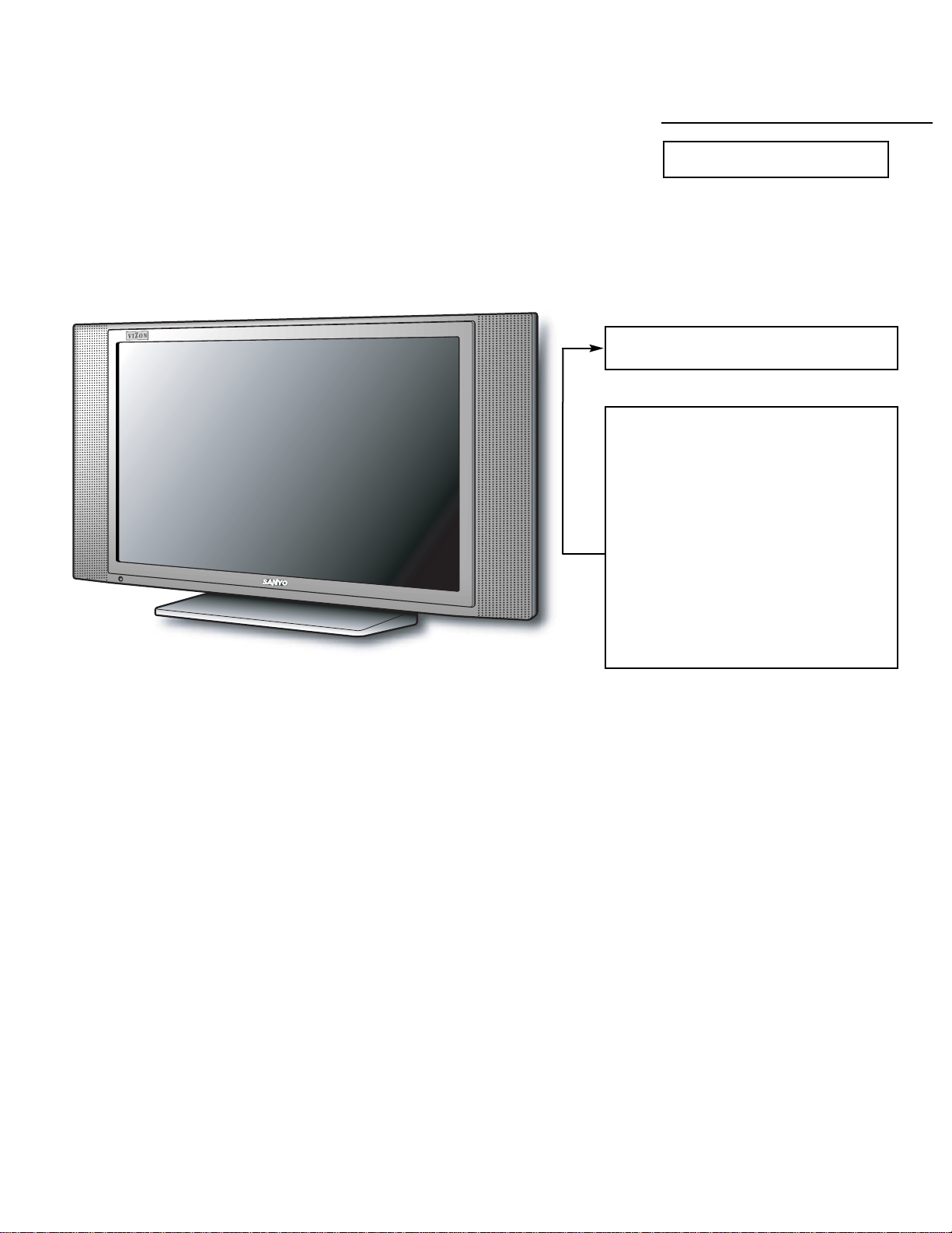
LCD . . . . . . . . . . . . . . . . . . . . . . . . . . . . V230W1-L02
Cabinet Dimensions
Width. . . . . . . . . . . . . . . . . . . . . . . . . . . . . 692mm
Height . . . . . . . . . . . . . . . . . . . . . . . . . . . . 385mm
Depth including base . . . . . . . . . . . . . . . . 181mm
REFERENCE No. SM780108
DP23845, N2TF, PRODUCT CODE 111377005
Contents
Safety Instructions . . . . . . . . . . . . . . . . . . 2
Service Adjustments . . . . . . . . . . . . . 3 - 14
Power Failure Circuit . . . . . . . . . . . . . . . 15
Mechanical Disassemblies. . . . . . . 16 – 17
Chassis Electrical Parts List . . . . . . 18 - 33
Cabinet Parts List . . . . . . . . . . . . . . . . . . 34
Component and Test Point
Locations . . . . . . . . . . . . . . . . . . . 35 – 39
Block Diagrams . . . . . . . . . . . . . . . . 40 – 45
Trouble Shooting Flow Charts . . . . 46 – 48
Control Port Functions. . . . . . . . . . . 49 – 50
Schematic Notes . . . . . . . . . . . . . . . . . . . 51
Pin Layouts. . . . . . . . . . . . . . . . . . . . . . . . 51
Capacitor and Resistor Codes . . . . . . . . 52
Schematic Diagrams . . . . . . . . . . . . 53 - 64
AS
FILE NO.
SERVICE MANUAL Remote Control Digital
Color Television
DP23845 (U.S.A.)
(CANADA)
ORIGINAL VERSION
Chassis No. 23845-00
NOTE: Match the Chassis No. on
the unit’s back cover with
the Chassis No. in the
Service Manual.
If the Original Version
Service Manual Chassis
No. does not match the
unit’s, additional Service
Literature is required. You
must refer to “Notices” to the
Original Service Manual
prior to servicing the unit.
Page 2
— 2 —
SAFETY INSTRUCTIONS
SAFETY PRECAUTIONS
1. Comply with all caution and safety-related notes provided
on the side of the cabinet, inside the cabinet, and on the
chassis,
2. When replacing a chassis in the cabinet, always be certain
that all the protective devices are installed properly, such
as control knobs, adjustment covers, shields and barriers.
3. Before replacing the back cover of the set, thoroughly
inspect the inside of the cabinet to see that no stray parts
or tools have been left inside.
ANTENNA COLD CHECK
Remove AC plug from the 120 VAC outlet and place a
jumper across the two blades. Connect one lead of an ohmmeter to the jumpered AC plug, and touch the other lead to
each exposed antenna terminal (UHF and VHF antenna terminals). The resistance must measure between 1M ohm and
5.2M ohm. Any resistance value below or above this range
indicates an abnormality which requires corrective action.
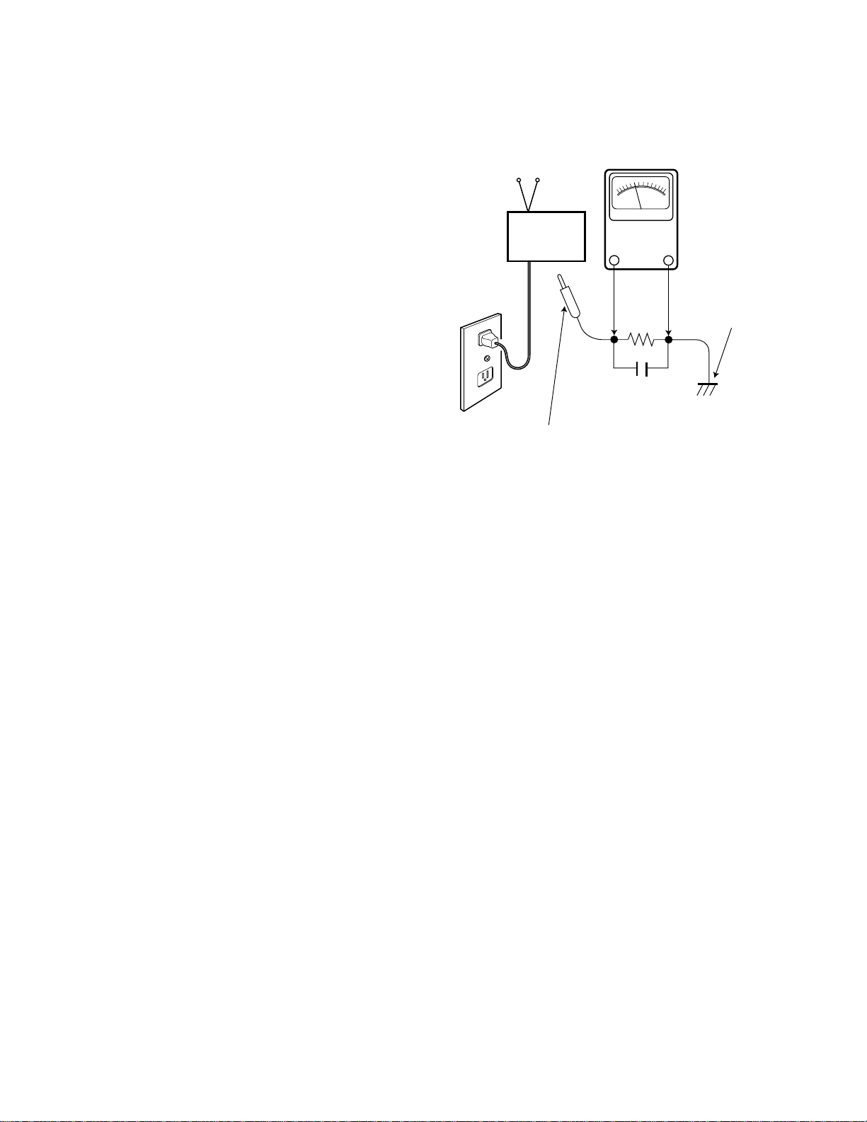
LEAKAGE CURRENT CHECK
Plug the AC line cord directly into a 120 VAC outlet. (Do not
use an isolation transformer for this check.) Use an AC voltmeter, that has 5000 ohms per volt or more sensitivity.
Connect a 1500 ohm 10 watt resistor, paralleled by a 0.15 µF
150 VAC capacitor, between a known good earth ground
(water pipe, conduit, etc.) and all exposed metal parts of the
cabinet (antennas, handle bracket, metal cabinet, screw
heads, metal overlays, control shafts, etc.). Measure the AC
voltage across the 1500 ohm resistor. The AC voltage
should not exceed 750 mV. A reading exceeding 750 mV
indicates that a dangerous potential exists. The fault must
be located and corrected. Repeat the above test with the
receiver power plug reversed.
NEVER RETURN A RECEIVER TO THE CUSTOMER
WITHOUT TAKING THE NECESSARY CORRECTIVE ACTION.
PRODUCT SAFETY NOTICE
When replacing components in a receiver, always keep in
mind the necessary product safety precautions. Pay special
attention to the replacement of components marked with a
star () in the parts list and in the schematic diagrams. To
ensure safe product operation, it is necessary to replace
those components with the exact same PARTS.
AC OUTLET
READING SHOULD NOT EXCEED 750 mV.
(5000 ohms per volt or more sensitivity)
TELEVISION
RECEIVER
To be touched to all of exposed metal parts.
Voltmeter Hook-up for Leakage Current Check.
AC VOLTMETER
1500 ohm
10 watt
0.15 µF 150V AC
Good earth ground
such as a water pipe,
conduit, etc.
Page 3
GENERAL
This set has an On-screen Service Menu system included in
the CPU that allows remote operation for most of the service adjustments.
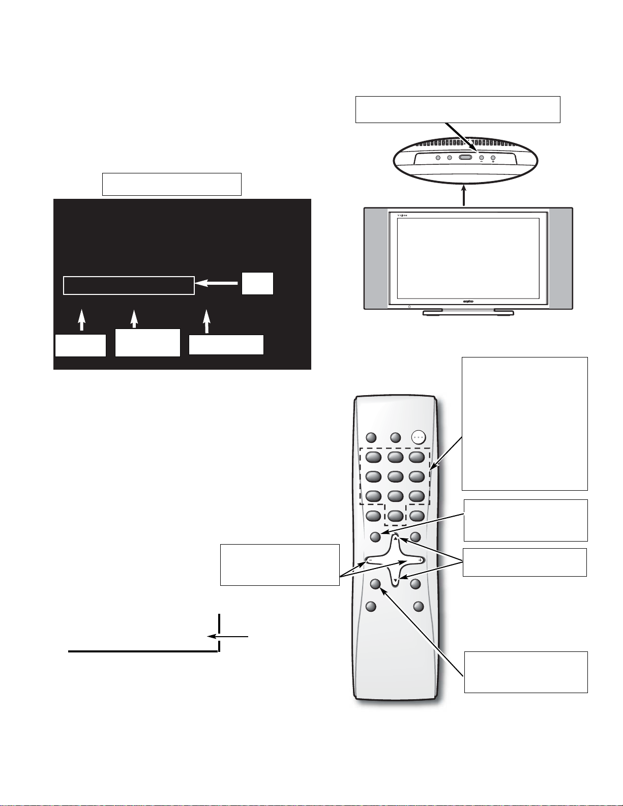
ON-SCREEN SERVICE MENU SYSTEM
1. Enter the Service Menu:
•While pressing the Volume (–) button on the televi-
sion, press the Number Key 1 on the remote control
unit. The Service Menu will now appear.
2. Service Adjustments:
•Press the or key to select the desired service
menu item you want to adjust. See page 4 for the
On-screen Service Menu.
Note: Press the Mute key to skip up 16 items.
•Use the + or – key or number keys to adjust the data.
The + or – keys will increase or decrease the data
sequentially. The number keys (0 ~ 7) toggle only
their respective bits between 1 and 0 and are used to
change the Sub-Address. For example to change bit
5 press the number 5 key. See below.
Note: Using the + or – is not recommended due to possi-
ble rapid changes.
3. Exit from the Service Menu:
•Press the MENU key to turn off
the Service Menu display.
Item No.
Hexadecimal
Data
Binary Data
Title
— 3 —
SERVICE ADJUSTMENTS
Service Menu Display
(b7) (b6) (b5) (b4) (b3) (b2) (b1) (b0)
0 1 0 1 0 1 1 0
BINARY DATA
(8 bit)
Menu:
Exit Service Menu
: Select Item
Volume + / –:
Adjust Service Menu
Mute:
Skip Next 16 items
Numeric:
1:
Enter Service Menu
0, 1, 2, 3, 4, 5, 6, 7:
Change Binary Data
1, 3, 4, 6, 7, 9:
Adjust White Balance
Volume – : Enter Service Menu
255_ 255
255 / 255 / 255
255 : 255 : 255__00000
M016___S0A __TV____RC00
V_ENH__GAIN__TV
000____01__00000001
POWER
CH
VOL
POWER
RESETINPUT
1 2 3
123
4 5 6
456
7 8 9
789
CAPTION SLEEP
MENU
CH
VOL VOL
MUTE
CH
V-GUIDE
0
0
RECALL
DISPLAY
PIX SHAPE
Page 4

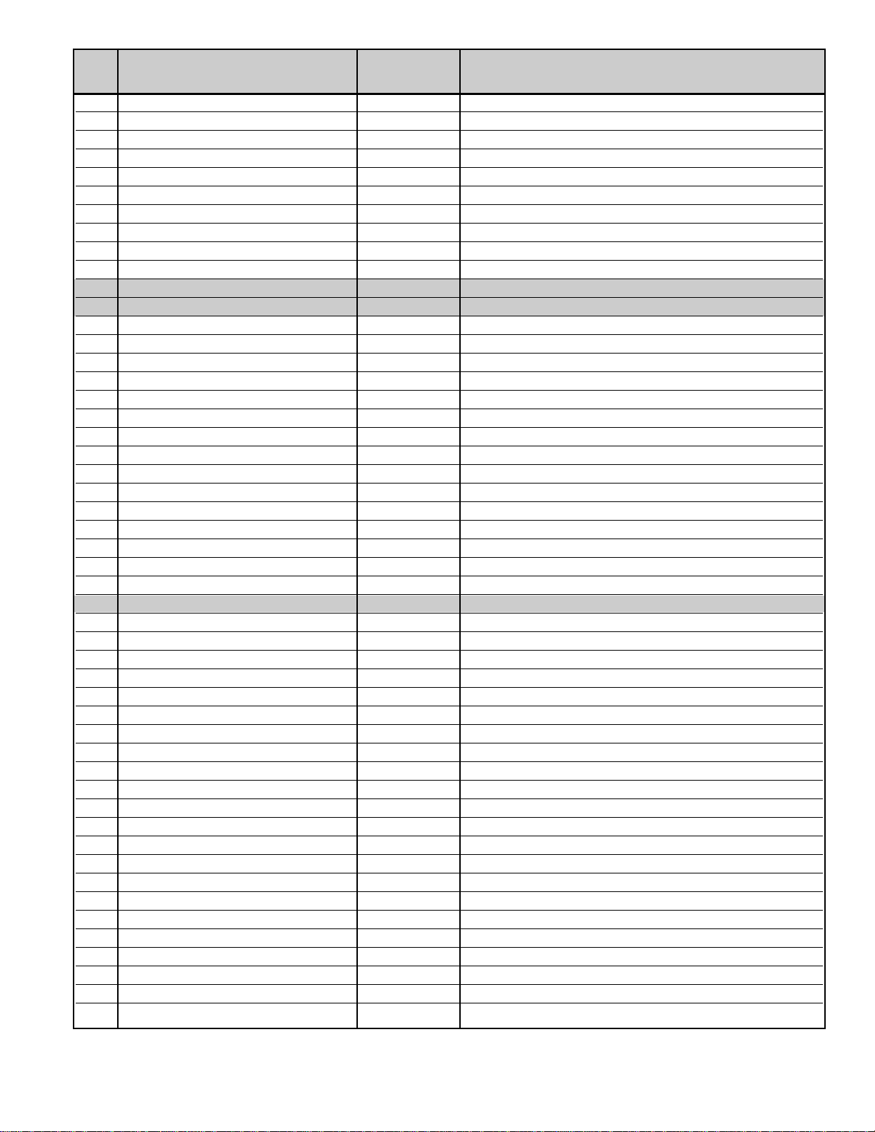
000 V ENH GAIN TV 01h RF input
001 V ENH GAIN OTHER 01h Except RF
002 V ENH MAX POINT TV 03h RF input
003 V ENH MAX POINT OTHER 03h Except RF
004 V ENH SLICE LEVEL TV 00h RF input
005 V ENH SLICE LEVEL OTHER 00h Except RF
006 FENH TV 01h RF input
007 FENH OTHER 01h Except RF
008 SHARPNESS GAIN TV 01h RF input
009 SHARPNESS GAIN OTHER 01h Except RF
00A SHARPNESS SLICE LEVEL TV 00h RF input
00B SHARPNESS SLICE LEVEL OTHER 00h Except RF
00C FBCLMPEX 01h
00D NOISE CANCEL TV 00h RF input
00E NOISE CANCEL OTHER 00h Except RF
00F SET DELAY–TV 0Dh RF input
010 SET DELAY–Video 0Bh Composite Video input
011 SET DELAY–OTHER 08h Except RF and Composite Video input
012 LTI GAIN TV 03h RF input
013 LTI GAIN OTHER 03h Except RF
014 LTI SLICE LEVEL TV 00h RF input
015 LTI SLICE LEVEL OTHER 00h Except RF
016 CTI GAIN TV 03h RF input
017 CTI GAIN OTHER 03h Except RF
018 CTI SLICE LEVEL TV 00h RF input
019 CTI SLICE LEVEL OTHER 00h Except RF
01A CONTRAST TV 30h RF input, (See Service Adjustments)
01B CONTRAST AV 30h Video1/2, Composite, S input
01C CONTRAST 480i/p 30h 480i/p input
01D CR OUTPUT GAIN TV 03h RF input
01E CR OUTPUT GAIN AV 03h Video1/2, Composite, S input
01F CR OUTPUT GAIN 480i/p 03h 480i/p input
020 CB OUTPUT GAIN TV 03h RF input
021 CB OUTPUT GAIN AV 03h Video1/2, Composite, S input
022 CB OUTPUT GAIN 480i/p 03h 480i/p input
023 CR OFFSET–TV 00h RF input
024 CR OFFSET–AV 00h Video1/2, Composite, S input
025 CR OFFSET–480i 01h 480i input
026 CR OFFSET–480p 00h 480p input
027 CB OFFSET–TV 00h RF input
028 CB OFFSET–AV 00h Video1/2, Composite, S input
029 CB OFFSET–480i 00h 480i input
02A CB OFFSET–480p 01h 480p input
02B HUE–TV 00h RF input
02C HUE–AV 00h Video1/2, Composite, S input
— 4 —
ON-SCREEN SERVICE MENU
No. Name Initial Data Note
• All data except in gray box area is fixed. Do not change for correct operation.
• Data in gray box is initial. Can be set according to adjustment information.
Page 5

02D HUE–480i/p 00h 480i/p input
02E TOF TV 01h RF input
02F TOF OTHER 01h Except RF
030 Y–CLAMP–MAIN 00h Except 480i/p
031 Y–CLAMP–480i 6Dh 480i input
032 Y–CLAMP–480p 6Dh 480p input
033 C–CLAMP–MAIN 00h Except 480i/p
034 C–CLAMP–480i 00h 480i input
035 C–CLAMP–480p 80h 480p input
036 C–CLAMP F–MAIN 00h Except 480i/p
037 C–CLAMP F–480i 6Fh 480i input
038 C–CLAMP F–480p 6Dh 480p input
039 COL–KILLER TV 07h RF input
03A COL–KILLER AV 07h Video1/2, Composite, S input
03B ACC TV 08h RF input
03C ACC AV 08h Video1/2, Composite, S input
03D PLL–TV AMP1 00h RF input
03E PLL–TV AMP2 04h ↓
03F PLL–TV AMP3 05h ↓
040 PLL–TV GAIN1 0Eh ↓
041 PLL–TV GAIN2 05h ↓
042 PLL–TV GAIN3 06h ↓
043 PLL–AV AMP1 00h Video1/2, Composite, S input
044 PLL–AV AMP2 04h ↓
045 PLL–AV AMP3 05h ↓
046 PLL–AV GAIN1 0Eh ↓
047 PLL–AV GAIN2 05h ↓
048 PLL–AV GAIN3 06h ↓
049 PLL–480i/p AMP1 00h Video3, Component(480i/p) input
04A PLL–480i/p AMP2 04h ↓
04B PLL–480i/p AMP3 05h ↓
04C PLL–480i/p GAIN1 0Eh ↓
04D PLL–480i/p GAIN2 05h ↓
04E PLL–480i/p GAIN3 06h ↓
04F HDPH COMP 00h RF, Composite input
050 HDPH S 02h S input
051 HDPH 480i 0Eh 480i input
052 HDPH 480p 00h 480p input
053 Y NOISE LIM TV 00h RF input
054 Y NOISE LIM OTHER 00h Except RF
055 Y NOISE GAIN TV 01h RF input
056 Y NOISE GAIN OTHER 00h Except RF
057 Y NOISE TV 01h RF input
058 Y NOISE OTHER 00h Except RF
059 COL–KILLER GAIN TV 01h RF input
05A COL–KILLER GAIN OTHER 01h Except RF
05B C NOISE LIM TV 01h RF input
05C C NOISE LIM OTHER 01h Except RF
05D C NOISE GAIN TV 00h RF input
05E C NOISE GAIN OTHER 00h Except RF
05F C NOISE TV 01h RF input
— 5 —
No. Name Initial Data Note
Page 6

060 C NOISE OTHER 00h Except RF
061 480i SUB–CONT 00h Component (480i) input (Difference)
062 480i SUB–BRIGHTNESS 00h ↓
063 480i SUB–COLOR 00h ↓
064 480i SUB–TINT 00h ↓
065 480i SUB–SHARP 00h ↓
066 480p SUB–CONT 00h Component (480p) input (Difference)
067 480p SUB–BRIGHTNESS 00h ↓
068 480p SUB–COLOR 0Ch ↓
069 480p SUB–TINT 00h ↓
06A 480p SUB–SHARP 00h ↓
06B AV SUB–CONT 00h Composite Video input (Standard)
06C AV SUB–BRIGHTNESS 0Fh ↓
06D AV SUB–COLOR 08h ↓
06E AV SUB–TINT 08h ↓
06F AV SUB–SHARP 10h ↓
070 S SUB–CONT 00h S Video input (Difference)
071 S SUB–BRIGHTNESS 00h ↓
072 S SUB–COLOR 00h ↓
073 S SUB–TINT 00h ↓
074 S SUB–SHARP 00h ↓
075 RF SUB–CONT 00h RF input (Difference)
076 RF SUB–BRIGHTNESS 00h ↓
077 RF SUB–COLOR 00h ↓
078 RF SUB–TINT 00h ↓
079 RF SUB–SHARP 00h ↓
07A 720p SUB-CONT 00h Component(720p) input (Difference)
07B 720p SUB-BRIGHT 00h ↓
07C 720p SUB-COLOR 00h ↓
07D 720p SUB-TINT 00h ↓
07E 720p SUB-SHARP F8h ↓
07F 1080i SUB-CONT 00h Component(1080i) input (Difference)
080 1080i SUB-BRIGHT 00h ↓
081 1080i SUB-COLOR 00h ↓
082 1080i SUB-TINT 00h ↓
083 1080i SUB-SHARP F8h ↓
084 480i D SUB-CONT 00h DVI(480i) input (Difference)
085 480i D SUB-BRIGHT 00h ↓
086 480i D SUB-COLOR 00h ↓
087 480i D SUB-TINT 00h ↓
088 480i D SUB-SHARP 00h ↓
089 480p D SUB-CONT 00h DVI(480p) input (Difference)
08A 480p D SUB-BRIGHT 00h ↓
08B 480p D SUB-COLOR 00h ↓
08C 480p D SUB-TINT 00h ↓
08D 480p D SUB-SHARP 00h ↓
08E 720p D SUB-CONT 00h DVI(720p) input (Difference)
08F 720p D SUB-BRIGHT 00h ↓
090 720p D SUB-COLOR 00h ↓
091 720p D SUB-TINT 00h ↓
092 720p D SUB-SHARP 00h ↓
— 6 —
No. Name Initial Data Note
Page 7

— 7 —
No. Name Initial Data Note
093 1080i D SUB-CONT 00h DVI(1080i) input (Difference)
094 1080i D SUB-BRIGHT 00h ↓
095 1080i D SUB-COLOR 00h ↓
096 1080i SUB-TINT 00h ↓
097 1080i SUB-SHARP 00h ↓
098 AUTO CONTRAST 0Ah Composite, S, Component input, Picture: Auto
099 AUTO TINT 22h ↓
09A AUTO COLOR 28h ↓
09B AUTO BRIGHT 20h ↓
09C AUTO SHARP 10h ↓
09D MANUAL AV CONTRAST 2Fh Composite, S, Component input, Picture: Manual
09E MANUAL AV TINT 20h ↓
09F MANUAL AV COLOR 28h ↓
0A0 MANUAL AV BRIGHT 20h ↓
0A1 MANUAL AV SHARP 10h ↓
0A2 GAME AV CONTRAST 10h Composite, S, Component input, Picture: Game
0A3 GAME AV TINT 20h ↓
0A4 GAME AV COLOR 10h ↓
0A5 GAME AV BRIGHT 20h ↓
0A6 GAME AV SHARP 07h ↓
0A7 WHITE-RF R 00h RF(TV) input, White Balance (Difference)
0A8 WHITE-RF G 00h ↓
0A9 WHITE-RF B 00h ↓
0AA BLACK-RF R 00h RF(TV) input, Black Balance (Difference)
0AB BLACK-RF G 00h ↓
0AC BLACK-RF B 00h ↓
0AD WHITE-AV R 52h Composite (AV) input, White Balance (Standard)
0AE WHITE-AV G 44h ↓
0AF WHITE-AV B 40h ↓
0B0 BLACK-AV R 30h Composite (AV) input, Black Balance (Standard)
0B1 BLACK-AV G 30h ↓
0B2 BLACK-AV B 30h ↓
0B3 WHITE-S R 00h S(AV) input, White Balance (Difference)
0B4 WHITE-S G 00h ↓
0B5 WHITE-S B 00h ↓
0B6 BLACK-S R 00h S(AV) input, Black Balance (Difference)
0B7 BLACK-S G 00h ↓
0B8 BLACK-S B 00h ↓
0B9 WHITE-480i R 00h 480i(Component) input, White Balance (Difference)
0BA WHITE-480i G 00h ↓
0BB WHITE-480i B 00h ↓
0BC BLACK-480i R 00h 480i(Component) input, Black Balance (Difference)
0BD BLACK-480i G 00h ↓
0BE BLACK-480i B 00h ↓
0BF WHITE-480p R 00h 480p(Component) input, White Balance (Difference)
0C0 WHITE-480p G 00h ↓
0C1 WHITE-480p B 00h ↓
0C2 BLACK-480p R 00h 480p(Component) input, Black Balance (Difference)
0C3 BLACK-480p G 00h ↓
0C4 BLACK-480p B 00h ↓
Page 8

— 8 —
No. Name Initial Data Note
0C5 WHITE-720p R 00h 720p (Component) input, White Balance (Difference)
0C6 WHITE-720p G 00h ↓
0C7 WHITE-720p B 00h ↓
0C8 BLACK-720p R 00h 720p (Component) input, Black Balance (Difference)
0C9 BLACK-720p G 00h ↓
0CA BLACK-720p B 00h ↓
0CB WHITE-1080i R 00h 1080i (Component) input, White Balance (Difference)
0CC WHITE-1080i G 00h ↓
0CD WHITE-1080i B 00h ↓
0CE BLACK-1080i R 00h 1080i (Component) input, Black Balance (Difference)
0CF BLACK-1080i G 00h ↓
0D0 BLACK-1080i B 00h ↓
0D1 WHITE-480i D R 00h 480i (DVI) input, White Balance (Difference)
0D2 WHITE-480i D G 00h ↓
0D3 WHITE-480i D B 00h ↓
0D4 BLACK-480i D R 00h 480i (DVI) input, Black Balance (Difference)
0D5 BLACK-480i D G 00h ↓
0D6 BLACK-480i D B 00h ↓
0D7 WHITE-480p D R 00h 480p (DVI) input, White Balance (Difference)
0D8 WHITE-480p D G 00h ↓
0D9 WHITE-480p D B 00h ↓
0DA BLACK-480p D R 00h 480p (DVI) input, Black Balance (Difference)
0DB BLACK-480p D G 00h ↓
0DC BLACK-480p D B 00h ↓
0DD WHITE-720p D R 00h 720p (DVI) input, White Balance (Difference)
0DE WHITE-720p D G 00h ↓
0DF WHITE-720p D B 00h ↓
0E0 BLACK-720p D R 00h 720p (DVI) input, Black Balance (Difference)
0E1 BLACK-720p D G 00h ↓
0E2 BLACK-720p D B 00h ↓
0E3 WHITE-1080i D R 00h 1080i (DVI) input, White Balance (Difference)
0E4 WHITE-1080i D G 00h ↓
0E5 WHITE-1080i D B 00h ↓
0E6 BLACK-1080i D R 00h 1080i (DVI) input, Black Balance (Difference)
0E7 BLACK-1080i D G 00h ↓
0E8 BLACK-1080i D B 00h ↓
0E9 CT-COOL R F6h Color Enhancer: Cool
0EA CT-COOL G FBh ↓
0EB CT-COOL B 00h ↓
0EC CT-NORM R 00h Color Enhancer: Normal
0ED CT-NORM G 00h ↓
0EE CT-NORM B 00h ↓
0EF CT-WARM R 00h Color Enhancer: Warm
0F0 CT-WARM G F2h ↓
0F1 CT-WARM B 00h ↓
0F2 SHARP F0 RF 02h RF input, Sharpness: Center
0F3 SHARP F0 OTHER 02h Other input, Sharpness: Center
0F4 SHARP F0 480p 02h 480p input, Sharpness: Center
0F5 GAMMA1 01h Under APL setting value
0F6 GAMMA2 01h Beyond APL setting value
Page 9
— 9 —
No. Name Initial Data Note
0F7 GAMMA APL 00h Gamma Threshold
0F8 NOSIG 00h Select Sync.
0F9 BSCB 00h Cut of Sub-Bass or Setup of Boost
0FA BSCT 00h Cut of Sub-Treble or Setup of Boost
0FB SUB-BASS 00h Setup of Cut Level of Sub Bass and Boost Level
0FC SUB-TREBLE 00h Setup of Cut Level of Sub Treble and Boost Level
0FD BBE-LOW 0Ah Setup of Low-Pass Boost Level (Lo contour)
0FE BBE-HIGH 08h Setup of High Region Boost Level (Process)
0FF AGC 00h AGC ON/OFF
100 AGC LEVEL 00h AGC Level Setup
101 WB ** White Balance Adjustment
102 BB ** Black Balance Adjustment
103 AUTO B-BRIGHT 00h Back Light Auto Bright (Absolute value)
104 BLIGHT-BRIGHT F0h Back Light Bright (PWM value)
105 BLIGHT-MID B0h Back Light Middle (PWM value)
106 BLIGHT-DARK 60h Back Light Dark (PWM value)
107 APL-SW 01h APL Switch
108 APL-PER 10h AI Cycle (8ms/step)
109 APL-LO 36h APL Low-Pass and Inside Region Threshold
10A APL-HI 48h APL Inside and High Region Threshold
10B APL-MIN 10h Gamma Minimum Value (Table No.)
10C APL-CEN 24h Gamma Center Value (Table No.)
10D APL-MAX 48h Gamma Maximum Value (Table No.)
10E APL-READ-NUM 05h Number of APL Read-out Times
10F APL-READ-PER 01h APL Read-out Cycle
110 APL-0 70h APL Read-out Value (APL=0%: Black)
111 APL-100 E0h APL Read-out Value (APL=100%: White)
112 POWER ERR 00h Power Failure History
113 OPTION **h Option Monitor (Read-out)
114 PANEL TIME1 **h Used Time of LCD Panel
115 PANEL TIME2 **h Used Time of Unit
116 OSD HP 00h OSD H-Phase
117 CCD HP 14h CCD H-Phase
118 CCD SLICER LEVEL 0Bh CCD Slicer Level
119 PASSWORD **h Password
11A VUP FULL 01h
11B VUP JUST 01h
11C VUP ZOOM 01h
11D VUP NORMAL 01h
11E VSC FULL 0Fh
11F VSC JUST 07h
120 VSC ZOOM 04h
121 VSC NORMAL 0Fh
122 HSC1 N FULL 10h
123 HSC1 N JUST 0Fh
124 HSC1 N ZOOM 0Fh
125 HSC1 N NORMAL 0Bh
126 HSC1 D FULL 1Fh
127 HSC1 D JUST 08h
128 HSC1 D ZOOM 1Eh
Page 10

— 10 —
No. Name Initial Data Note
129 HSC1 D NORMAL 10h
12A HSC2 N FULL 13h
12B HSC2 N JUST 07h
12C HSC2 N ZOOM 07h
12D HSC2 N NORMAL 0Ch
12E HSC2 D FULL 0Fh
12F HSC2 D JUST 0Fh
130 HSC2 D ZOOM 0Fh
131 HSC2 D NORMAL 11h
132 HST FULL 0Ah
133 HST JUST 0Fh
134 HST ZOOM 0Fh
135 HST NORMAL 04h
136 VST FULL 34h
137 VST JUST 54h
138 VST ZOOM 7Eh
139 VST NORMAL 34h
13A VUP FULL 480p 01h
13B VUP JUST 480p 01h
13C VUP ZOOM 480p 01h
13D VUP NORMAL 480p 01h
13E VSC FULL 480p 0Fh
13F VSC JUST 480p 07h
140 VSC ZOOM 480p 04h
141 VSC NORMAL 480p 0Fh
142 HSC1 N FULL 480p 10h
143 HSC1 N JUST 480p 0Fh
144 HSC1 N ZOOM 480p 07h
145 HSC1 N NORMAL 480p 0Bh
146 HSC1 D FULL 480p 1Fh
147 HSC1 D JUST 480p 08h
148 HSC1 D ZOOM 480p 0Eh
149 HSC1 D NORMAL 480p 10h
14A HSC2 N FULL 480p 13h
14B HSC2 N JUST 480p 07h
14C HSC2 N ZOOM 480p 07h
14D HSC2 N NORMAL 480p 0Ch
14E HSC2 D FULL 480p 0Fh
14F HSC2 D JUST 480p 0Fh
150 HSC2 D ZOOM 480p 0Fh
151 HSC2 D NORMAL 480p 11h
152 HST FULL 480p 12h
153 HST JUST 480p 18h
154 HST ZOOM 480p 16h
155 HST NORMAL 480p 0Ah
156 VST FULL 480p 3Dh
157 VST JUST 480p 5Ch
158 VST ZOOM 480p 89h
159 VST NORMAL 480p 3Dh
15A VUP 480i D 01h
15B VUP 480p D 01h
Page 11

— 11 —
No. Name Initial Data Note
15C VUP 720p D 01h
15D VUP 720p A 01h
15E VUP 1080i D 00h
15F VUP 1080i A 00h
160 VSC 480i D 0Ah
161 VSC 480p D 12h
162 VSC 720p D 10h
163 VSC 720p A 10h
164 VSC 1080i D 12h
165 VSC 1080i A 12h
166 HSC1N 480i D 0Fh
167 HSC1N 480p D 0Bh
168 HSC1N 720p D 10h
169 HSC1N 720p A 1Dh
16A HSC1N 1080i D 1Ch
16B HSC1N 1080i A 1Fh
16C HSC1D 480i D 1Eh
16D HSC1D 480p D 15h
16E HSC1D 720p D 11h
16F HSC1D 720p A 1Fh
170 HSC1D 1080i D 14h
171 HSC1D 1080i A 16h
172 HST 480i D 21h
173 HST 480p D 0Ch
174 HST 720p D 0Fh
175 HST 720p A 0Ah
176 HST 1080i D 0Bh
177 HST 1080i A 08h
178 VST 480i D 44h
179 VST 480p D 38h
17A VST 720p D 1Eh
17B VST 720p A 1Eh
17C VST 1080i D 1Fh
17D VST 1080i A 20h
17E H RANGE 480i 04h
17F 480I DATA1 31h
180 480I DATA2 81h
181 480I DATA3 40h
182 480I DATA4 83h
183 H RANGE 480p 02h
184 480P DATA1 71h
185 480P DATA2 81h
186 480P DATA3 80h
187 480P DATA4 83h
188 H RANGE 720p 04h
189 720P DATA1 F1h
18A 720P DATA2 83h
18B 720P DATA3 20h
18C 720P DATA4 83h
18D H RANGE 1080i 02h
18E 1080I DATA1 B1h
Page 12

— 12 —
No. Name Initial Data Note
18F 1080I DATA2 83h
190 1080I DATA3 60h
191 1080I DATA4 83h
192 V RANGE 480i 17h
193 R Gain 480i D FFh
194 R Gain 480p D FFh
195 R Gain 720p D FFh
196 R Gain 720p A 42h
197 R Gain 1080i D FFh
198 R Gain 1080i A 42h
199 G Gain 480i D FFh
19A G Gain 480p D FFh
19B G Gain 720p D FFh
19C G Gain 720p A 42h
19D G Gain 1080i D FFh
19E G Gain 1080i A 42h
19F B Gain 480i D FFh
1A0 B Gain 480p D FFh
1A1 B Gain 720p D FFh
1A2 B Gain 720p A 42h
1A3 B Gain 1080i D FFh
1A4 B Gain 1080i A 42h
1A5 R offAD 480i D 00h
1A6 R offAD 480p D 00h
1A7 R offAD 720p D 00h
1A8 R offAD 720p A 00h
1A9 R offAD 1080i D 00h
1AA R offAD 1080i A 00h
1AB R off 480i D 80h
1AC R off 480p D 80h
1AD R off 720p D 80h
1AE R off 720p A 80h
1AF R off 1080i D 80h
1B0 R off 1080i A 80h
1B1 G offAD 480i D 00h
1B2 G offAD 480p D 00h
1B3 G offAD 720p D 00h
1B4 G offAD 720p A 00h
1B5 G offAD 1080i D 00h
1B6 G offAD 1080i A 00h
1B7 G off 480i D 00h
1B8 G off 480p D 00h
1B9 G off 720p D 00h
1BA G off 720p A 12h
1BB G off 1080i D 00h
1BC G off 1080i A 12h
1BD B offAD 480i D 00h
1BE B offAD 480p D 00h
1BF B offAD 720p D 00h
1C0 B offAD 720p A 00h
1C1 B offAD 1080i D 00h
Page 13
— 13 —
No. Name Initial Data Note
1C2 B offAD 1080i A 00h
1C3 B off 480i D 80h
1C4 B off 480p D 80h
1C5 B off 720p D 80h
1C6 B off 720p A 80h
1C7 B off 1080i D 80h
1C8 B off 1080i A 80h
1C9 R001 00h ROM Correction Data
1CA 00h ROM Correction Data
1CB 00h ROM Correction Data
↓↓↓
↓↓↓
↓↓↓
261 00h ROM Correction Data
262 00h ROM Correction Data
263 00h ROM Correction Data
Page 14
— 14 —
SERVICE ADJUSTMENTS (Continued)
WHITE BALANCE ADJUSTMENT
Composite (External Video Input)
1. Connect a color-bar generator to the external composite video input terminal.
2. Switch the generator to the white pattern.
3. Set the television to following conditions:
Picture: AUTO
Color Enhancer: Normal
Back Light: Bright
Display Area: 16:9
4. Enter the Service Mode. The Menu display will appear.
5. Select “White Balance Adjustment” Menu (No. 101).
6. Adjust Red, Green, and Blue Levels alternately with 1, 3,
4, 6, 7, or 9 keys to produce normal black and white
picture in highlight areas.
The White Balance Level adjustment data will be
written automatically in the Service Menu No. 0AD(R),
No. 0AE(G), and No. 0AF(B).
Note: One or two data of RGB should be left at ”52” for
normal contrast level. Do not change the data to
more than “52.”
Other Inputs
Caution: White Balance Adjustment of Composite must
be completed before attempting other input
adjustments.
White Balance Adjustment for other modes [RF, S (Y/C),
Component (480i/ 480p)] may be unnecessary if the adjustment of Composite is OK.
1. Connect a color-bar generator to the preferred video
input terminal.
2. Switch the generator to the white pattern.
3. Set the television to following conditions:
Picture: AUTO
Color Enhancer: Normal
Back Light: Bright
Display Area: 16:9
4. Enter the Service Mode.The Menu display will appear.
5. Select “White Balance Adjustment” Menu (No. 101).
6. Adjust Red, Green, and Blue Levels alternately with 1, 3,
4, 6, 7, or 9 key to produce normal black and white picture
in highlight areas.
The White Balance Level adjustment data will be written
automatically in the following Service Menu:
RF No 0A7 (R), 0A8 (G), 0A9 (B)
S (Y/C) No.0B3 (R), 0B4 (G), 0B5 (B)
Component (480i) No.0B9 (R), 0BA (G), 0BB (B)
Component (480p) No.0BF (R), 0C0 (G), 0C1 (B)
BLACK BALANCE ADJUSTMENT
Black Balance Adjustment may be unnecessary if the White
Balance Adjustment of Composite is OK.
Composite (External Video Input)
1. Connect a color-bar generator to the external (composite) video input terminal.
2. Switch the generator to the dark grey pattern (“30%
white” recommended).
3. Set the television to following conditions:
Picture: AUTO
Color Enhancer: Normal
Back Light: Bright
Display Area: 16:9
4. Enter the Service Mode. The Menu display will appear.
5. Select “Black Balance Adjustment” Menu (No. 102).
6. Adjust Red, Green, and Blue Levels alternately with 1,
3, 4, 6, 7, or 9 key to produce normal black and white
picture in dark grey areas. The Black Balance Level
adjustment data will be written automatically in the
Service Menu No. 0B0(R), No. 0B1(G), and No. 0B2(B).
Other Inputs
Caution: Black Balance Adjustment of Composite must
be completed before attempting other input
adjustments.
1. Connect a color-bar generator to the preferred video
input terminal.
2. Switch the generator to the dark gray pattern.
3. Set the television to following conditions:
Picture: AUTO
Color Enhancer: Normal
Back Light: Bright
Display Area: 16:9
4. Enter the Service Mode.The Menu display will appear.
5. Select “Black Balance Adjustment” Menu (No. 102).
6. Adjust Red, Green, and Blue Levels alternately with 1,
3, 4, 6, 7, or 9 key to produce normal black and white
picture in dark grey areas. The Black Balance Level
adjustment data will be written automatically in the following Service Menu.
RF No 0AA (R), 0AB (G), 0AC (B)
S (Y/C) No. 0B6 (R), 0B7 (G), 0B8 (B)
Component (480i) No. 0BC (R), 0BD (G), 0BE (B)
Component (480p) No. 0C2 (R), 0C3 (G), 0C4 (B)
Component (720p) No. 0C8 (R), 0C9 (G), 0CA (B)
Component (1080i) No. 0CE (R), 0CF (G), 0D0 (B)
DVI (480i) No. 0D4 (R), 0D5 (G), 0D6 (B)
DVI (480p) No. 0DA (R), 0DB (G), 0DC (B)
DVI (720p) No. 0E0 (R), 0E1 (G), 0E2 (B)
1
2
3
4 5 6
7 98
RD(–)
RD(+)
BD(–)
BD(+)
(N/A)
GD(–)
(N/A)
GD(+)
(N/A)
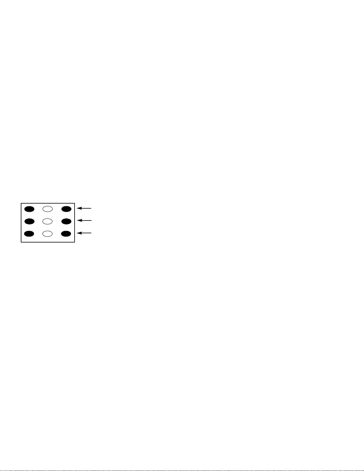
Remote Control Number keys’ functions in Service Menu
“White Balance Adjustment”
FOR RED LEVEL ADJUSTMENT
FOR BLUE LEVEL ADJUSTMENT
FOR GREEN LEVEL ADJUSTMENT
Page 15

— 15 —
CPU (IC801) is programmed so the set will go to the standby mode when there is circuit failure as described below.
(Refer to “Block Diagram Power Lines” and “Block
Diagram Power Board.”)
1. Power Failure 1: Detected voltage failure for digital
circuit. (Connected to IC801 pin 1.)
2. Power Failure 2: Detected voltage failure for ana-
log circuit. (Connected to IC801 pin 16.)
(Normal: High; Failure: Low)
POWER FAILURE CIRCUIT
Note: If power failure is detected 3 times in 15 minutes, the
set will enter the standby mode and cannot be
switched On. To reset the operating programs of the
CPU it is necessary to disconnect the AC cord for a
short time.
History of Power Failure
When finishing the repair or stopping the Power Failure, the
history of past failures can be checked.
To see the history
1. Enter the service mode. See “Service Adjustments”
page 3.
2. Select Item No.112 POWER ERR from the Service
Adjustment Data Table.
Note: If simultaneous failures have been detected, the
sum of each data is displayed.
For example:
Power failures 1 & 2
01h + 02h = 03h(3)
Attention:
After finishing service, reset the data of Item No. 112 with
the + or – keys to
““0000hh((00))..””
Failure Name Data
No Failure 00h(0)
Power Failure 1 01h(1)
Power Failure 2 02h(2)
History of Power Failures (Item No. 0C9)
Page 16
— 16 —
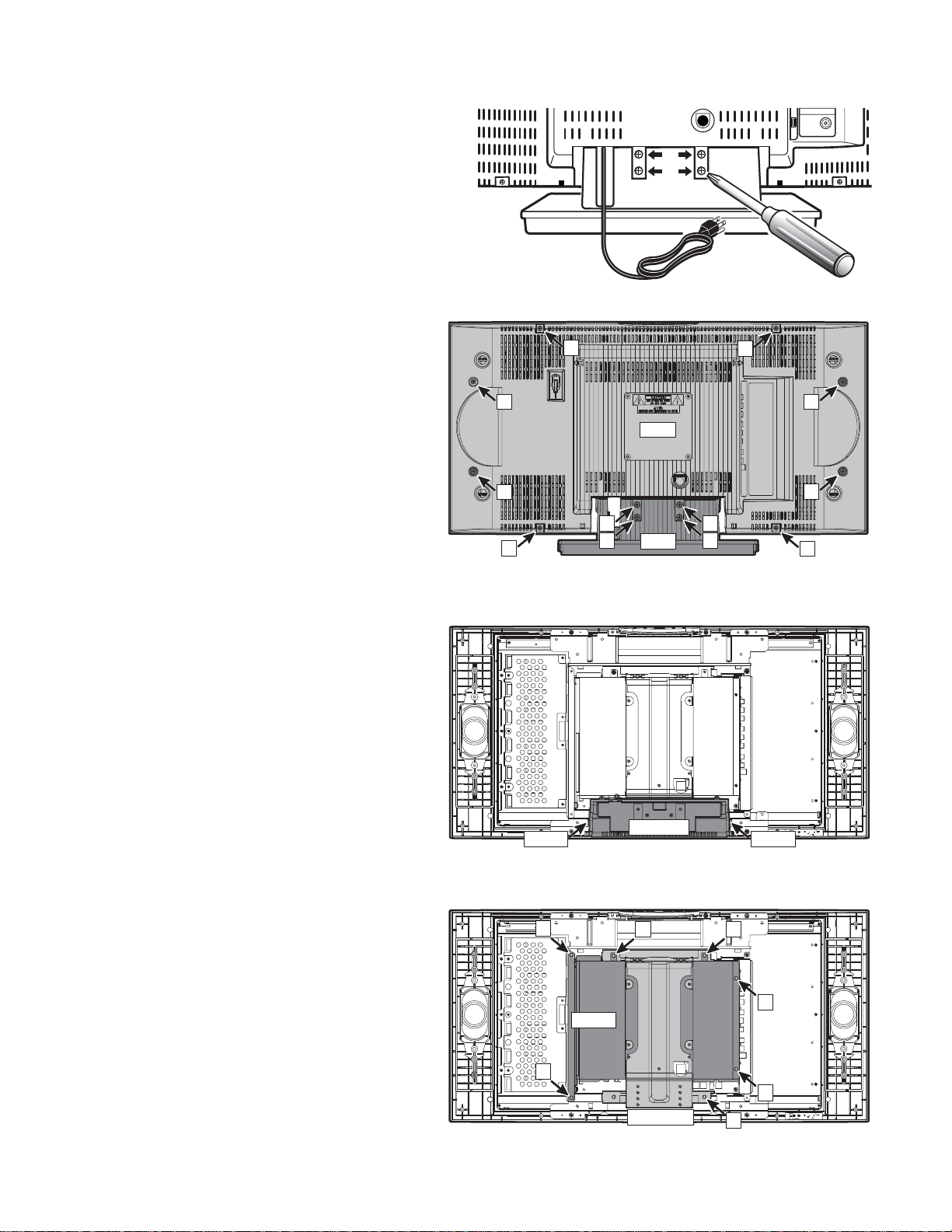
STAND REMOVAL
Note: Position TV face down on a padded or cush-
ioned surface to protect the screen and finish.
Remove 4 screws to take the stand off.
MECHANICAL DISASSEMBLY
CABINET BACK REMOVAL
Remove 8 screws (B : 4X14) to take the cabinet back
(C/B) off.
Note: The cabinet back can be removed without
removing the stand.
CABINET BOTTOM REMOVAL
Press 2 hooks inside to remove the cabinet bottom
(C/BTM).
SHIELD BACK REMOVAL
Remove 6 screws (C: 3X10) to remove the shield back
(SH/B).
MOUNTING BRACKET REMOVAL
Remove a screw (D: 3X10) to remove the mounting
bracket (M/BRKT).
CAUTION: This LCD TV uses several different kinds of
screws. Using the correct screw is necessary to prevent damage. Lead wires must
be redressed to their previous locations
after servicing.
VHF
UHF
CATV
TUNER
B
B
B
B
C/B
B
A
A
B
STD
A
A
B
B
Hook Hook
C
C/BTM
C
C
C
SH/B
C
C
M/BRKT
D
Page 17
— 17 —
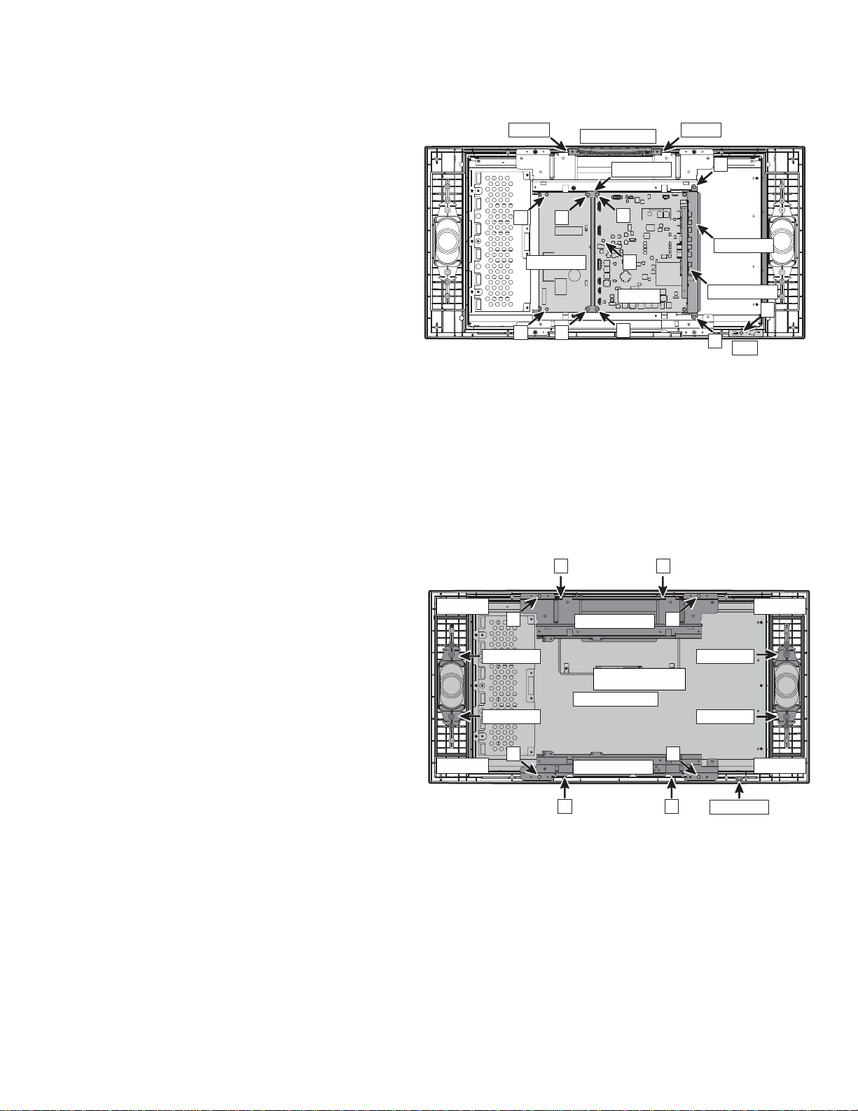
MAIN BOARD REMOVAL
Remove 5 screws (E: 3X10) to remove the main board
with the terminal base (TMNL/B) and audio output jacks
(MO/JACK) (assembly parts).
RC BOARD REMOVAL
Remove a screw (F: 4X14) to remove the RC board.
POWER BOARD REMOVAL
Remove 4 screws (G: 3X10) to remove the power board
with the chassis holder (CH/HLD) (assembly parts).
CONTROL BOARD REMOVAL
Press 2 hooks inside to remove the control board with
the panel top and button assembly.
SPEAKER REMOVAL
Remove 4 holders (SP/HLD) to remove speakers.
LCD PANEL REMOVAL
1. Remove 4 screws (H: 3X10) to remove the LCD
panel with the top (HLD/PNL-T) and bottom
(HLD/PNL-B) panel holders.
2. Remove 2 screws (J: 3X10) to remove the top
panel holder (HLD/PNL-T).
3. Remove 2 screws (I: 3X10) to remove the bottom
panel holder (HLD/PNL-B).
CABINET FRONT REMOVAL
1. Complete previous disassembly procedures.
2. Remove spacer (Buffer tape) and DEC-RC
(Decoration for remote control receiver).
Note: The spacers can be reused.
Chassis Base
CONTROL
GG
CH/HLD
E
HookHook
E
Spacer
H
SP/HLD
SP/HLD
POWER
GG
E
MAIN
E
HLD/PNL-T
LCD PANEL
JJ
H
TMNL/B
MO/JACK
E
RC
SP/HLD
SP/HLD
F
Spacer
Spacer
H
HLD/PNL-B
I I
H
Spacer
DEC-RC
Page 18

— 18 —
CHASSIS ELECTRICAL PARTS LIST
CAUTION: To Protect against electrical shock and for continued product safety, refer to SAFETY PRECAUTIONS,
and PRODUCT SAFETY NOTICE on Page 2.
PRODUCT SAFETY NOTICE
PRODUCT SAFETY SHOULD BE CONSIDERED WHEN A REPLACEMENT IS MADE IN ANY AREA OF A RECEIVER.
COMPONENTS INDICATED BY A STAR ( ) IN THIS PARTS LIST AND THE SCHEMATIC DIAGRAM DESIGNATE
COMPONENTS IN WHICH SAFETY CAN BE OF SPECIAL SIGNIFICANCE. IT IS PARTICULARLY RECOMMENDED
THAT ONLY PARTS DESIGNATED ON THE FOLLOWING PARTS LIST BE USED FOR COMPONENT REPLACEMENT
DESIGNATED BY A STAR. NO DEVIATIONS FROM RESISTANCE, WATTAGE, AND VOLTAGE RATINGS MAY BE MADE
FOR REPLACEMENT ITEMS DESIGNATED BY A STAR.
Schematic
Location
Part No.
Description
Schematic
Location
Part No.
Description
Note: Schematic part location numbers may not always match with the part descriptions.
The part descriptions are correct and should be used.
CAPACITORS
NOTES:
Read description of the Capacitor as follows:
(Example)
CERAMIC 100P K 50V
Rated Voltage
Tolerance Symbols:
less than 10PF
A . .Not specified
B . .±0.1PF C . .±0.25PF
D . .±0.5PF F . .±1PF
G . .±2PF R . .+0.25 - 0PF
S . .+0 - 0.25PF E . .+0 - 1PF
more than 10PF
A . .Not specified
B . .±0.1% C . .±0.25%
D . .±0.5% F . .±1%
G . .±2% H . .±3%
J . .±5% K . .±10%
L . .±15% M . .±20%
N . .±30% P . .+100 - 0%
Q . .+30 - 10% T . .+50 - 10%
U . .+75 - 10% V . .+20 - 10%
W .+100 - 10% X . .+40 - 20%
Y . .+150 - 10% Z . .+80 - 20%
Rated Value: P...Pico Farad U...Micro Farad
Material:
CERAMIC . . . . . .Ceramic
MT-PAPER . . . . .Metalized Paper
POLYESTER . . .Polyester
MT-POLYEST . .Metalized Polyester
POLYPRO . . . . .Polypropylene
MT-POLYPRO . .Metalized Polypropylene
COMPO-FILM . .Composite Film
MT-COMPO . . . .Metalized Composite
STYRENE . . . . . .Styrene
TA-SOLID . . . . . .Tantalum Solid
AL-SOLID . . . . . .Aluminum Solid
ELECT . . . . . . . .Electrolytic
NP-ELECT . . . . .Non-Polarized Electrolytic
OS-SOLID . . . . .Aluminum Solid with Organic
Semiconductive Electrolytic
C002 403 296 9502 ELECT 100U M 16V
403 391 5102 ELECT 100U M 16V
C003 403 184 8402 ELECT 4.7U M 25V
403 391 5706 ELECT 4.7U M 25V
C006 404 087 2702 ELECT 470U M 25V
C007 404 087 2702 ELECT 470U M 25V
C021 403 345 6605 CERAMIC 1U Z 10V
C022 403 224 5903 CERAMIC 3300P K 50V
C023 403 345 6605 CERAMIC 1U Z 10V
C024 403 224 5903 CERAMIC 3300P K 50V
C026 403 364 5900 CERAMIC 0.22U K 16V
C027 403 364 5900 CERAMIC 0.22U K 16V
C028 403 364 5900 CERAMIC 0.22U K 16V
C029 403 364 5900 CERAMIC 0.22U K 16V
C041 404 087 2702 ELECT 470U M 25V
C108 403 184 8501 ELECT 2.2U M 50V
403 398 6508 ELECT 2.2U M 50V
C109 403 235 6203 CERAMIC 0.01U Z 50V
C112 403 224 6306 CERAMIC 0.033U Z 50V
C114 403 408 6207 NP-ELECT 10U M 16V
C601 403 175 7209 ELECT 10U M 16V
403 391 5508 ELECT 10U M 16V
C603 403 224 6306 CERAMIC 0.033U Z 50V
C605 403 224 6306 CERAMIC 0.033U Z 50V
C606 403 235 1109 CERAMIC 270P J 50V
C607 403 224 6009 CERAMIC 4700P K 50V
C608 403 224 6009 CERAMIC 4700P K 50V
C609 403 224 6009 CERAMIC 4700P K 50V
C618 403 296 9502 ELECT 100U M 16V
403 391 5102 ELECT 100U M 16V
C619 403 387 4904 ELECT 100U M 6.3V
403 394 1309 ELECT 100U M 6.3V
C631 404 087 2702 ELECT 470U M 25V
C632 404 087 2702 ELECT 470U M 25V
Page 19

— 19 —
Schematic
Location
Part No.
Description
C633 403 279 0106 CERAMIC 0.1U Z 25V
C634 403 279 0106 CERAMIC 0.1U Z 25V
C641 404 084 2903 ELECT 1000U M 16V
C644 403 309 1400 CERAMIC 1.0U Z 10V
403 336 5600 CERAMIC 1.0U Z 10V
C645 403 175 7209 ELECT 10U M 16V
403 391 5508 ELECT 10U M 16V
C647 404 087 2702 ELECT 470U M 25V
C656 403 279 0106 CERAMIC 0.1U Z 25V
C657 403 387 4904 ELECT 100U M 6.3V
403 394 1309 ELECT 100U M 6.3V
C658 403 387 4904 ELECT 100U M 6.3V
403 394 1309 ELECT 100U M 6.3V
C659 403 279 0106 CERAMIC 0.1U Z 25V
C661 404 084 2903 ELECT 1000U M 16V
C663 403 309 1400 CERAMIC 1U Z 10V
403 336 5600 CERAMIC 1U Z 10V
C666 404 087 2702 ELECT 470U M 25V
C671 403 387 4904 ELECT 100U M 6.3V
403 394 1309 ELECT 100U M 6.3V
C672 403 279 0106 CERAMIC 0.1U Z 25V
C673 403 387 4904 ELECT 100U M 6.3V
403 394 1309 ELECT 100U M 6.3V
C674 403 279 0106 CERAMIC 0.1U Z 25V
C676 403 387 4904 ELECT 100U M 6.3V
403 394 1309 ELECT 100U M 6.3V
C677 403 279 0106 CERAMIC 0.1U Z 25V
C678 403 387 4904 ELECT 100U M 6.3V
403 394 1309 ELECT 100U M 6.3V
C679 403 279 0106 CERAMIC 0.1U Z 25V
C681 403 387 4904 ELECT 100U M 6.3V
403 394 1309 ELECT 100U M 6.3V
C682 403 279 0106 CERAMIC 0.1U Z 25V
C683 403 387 4904 ELECT 100U M 6.3V
403 394 1309 ELECT 100U M 6.3V
C684 403 279 0106 CERAMIC 0.1U Z 25V
C686 403 387 4904 ELECT 100U M 6.3V
403 394 1309 ELECT 100U M 6.3V
C687 403 279 0106 CERAMIC 0.1U Z 25V
C688 403 387 4904 ELECT 100U M 6.3V
403 394 1309 ELECT 100U M 6.3V
C689 403 279 0106 CERAMIC 0.1U Z 25V
C803 403 279 0106 CERAMIC 0.1U Z 25V
C804 403 279 0106 CERAMIC 0.1U Z 25V
C806 403 279 0106 CERAMIC 0.1U Z 25V
C811 403 387 5109 ELECT 220U M 6.3V
403 394 9305 ELECT 220U M 6.3V
C851 403 235 0607 CERAMIC 100P J 50V
C852 403 345 6605 CERAMIC 1U Z 10V
C854 403 309 1400 CERAMIC 1U Z 10V
403 336 5600 CERAMIC 1.0U Z 10V
C861 403 393 2109 CERAMIC 4.7U K 6.3V
C862 403 393 2109 CERAMIC 4.7U K 6.3V
C876 403 309 1400 CERAMIC 1U Z 10V
403 336 5600 CERAMIC 1.0U Z 10V
C877 403 279 0106 CERAMIC 0.1U Z 25V
C886 403 235 6203 CERAMIC 0.01U Z 50V
C1001 403 175 7209 ELECT 10U M 16V
403 391 5508 ELECT 10U M 16V
C1002 403 175 7209 ELECT 10U M 16V
403 391 5508 ELECT 10U M 16V
C1005 403 175 7209 ELECT 10U M 16V
403 391 5508 ELECT 10U M 16V
C1007 403 175 7209 ELECT 10U M 16V
403 391 5508 ELECT 10U M 16V
C1008 403 175 7209 ELECT 10U M 16V
403 391 5508 ELECT 10U M 16V
C1201 403 235 6203 CERAMIC 0.01U Z 50V
C1202 403 235 6203 CERAMIC 0.01U Z 50V
C1204 403 296 9502 ELECT 100U M 16V
403 391 5102 ELECT 100U M 16V
C1206 403 408 6207 NP-ELECT 10U M 16V
C1600 403 309 1400 CERAMIC 1U Z 10V
C1601 403 309 1400 CERAMIC 1U Z 10V
C1602 404 096 0508 MT-POLYEST 0.1U M 275V
C1603 404 096 0508 MT-POLYEST 0.1U M 275V
C1604 403 370 1507 CERAMIC 0.1U K 50V
C1605 403 222 1303 CERAMIC 1000P K 1K
403 262 1806 CERAMIC 1000P K 1K
403 271 9602 CERAMIC 1000P K 1K
C1606 403 222 1303 CERAMIC 1000P K 1K
403 262 1806 CERAMIC 1000P K 1K
403 271 9602 CERAMIC 1000P K 1K
C1607 403 370 1507 CERAMIC 0.1U K 50V
C1608 404 075 5005 ELECT 470U M 200V
404 096 2700 ELECT 470U M 200V
C1609 403 235 5404 CERAMIC 1500P K 50V
C1610 403 370 1507 CERAMIC 0.1U K 50V
C1611 403 420 8401 ELECT 47U M 50V
C1612 403 235 4902 CERAMIC 470P K 50V
C1613 403 222 1303 CERAMIC 1000P K 1K
403 262 1806 CERAMIC 1000P K 1K
403 271 9602 CERAMIC 1000P K 1K
C1614 403 419 9501 ELECT 1000U M 35V
C1615 403 419 9501 ELECT 1000U M 35V
C1617 403 419 9501 ELECT 1000U M 35V
C1618 403 222 1907 CERAMIC 2200P K 1K
403 232 0204 CERAMIC 2200P K 1K
403 263 6305 CERAMIC 2200P K 1K
C1619 403 222 1303 CERAMIC 1000P K 1K
403 262 1806 CERAMIC 1000P K 1K
403 271 9602 CERAMIC 1000P K 1K
C1620 403 222 1303 CERAMIC 1000P K 1K
403 262 1806 CERAMIC 1000P K 1K
403 271 9602 CERAMIC 1000P K 1K
C1621 403 180 1605 MT-POLYEST 0.1U K 400V
C1622 403 419 9303 ELECT 1000U M 25V
Schematic
Location
Part No.
Description
Page 20

— 20 —
Schematic
Location
Part No.
Description
Schematic
Location
Part No.
Description
C1623 403 419 9303 ELECT 1000U M 25V
C1624 403 419 9402 ELECT 680U M 25V
C1625 404 088 2909 CERAMIC 1000P M 250V
C1626 404 084 3405 ELECT 1000U M 25V
C1628 404 084 2408 ELECT 470U M 6.3V
C1629 404 088 2909 CERAMIC 1000P M 250V
C1630 404 088 2909 CERAMIC 1000P M 250V
C1632 403 233 0807 ELECT 10U M 50V
C1831 403 279 0106 CERAMIC 0.1U Z 25V
C1832 403 387 5307 ELECT 47U M 6.3V
403 392 1202 ELECT 47U M 6.3V
C1899 403 279 0106 CERAMIC 0.1U Z 25V
C1962 403 393 2109 CERAMIC 4.7U K 6.3V
C1963 403 393 2109 CERAMIC 4.7U K 6.3V
C2001 403 279 0106 CERAMIC 0.1U Z 25V
C2002 403 235 6203 CERAMIC 0.01U Z 50V
C2003 403 279 0106 CERAMIC 0.1U Z 25V
C2004 403 387 5307 ELECT 47U M 6.3V
403 392 1202 ELECT 47U M 6.3V
C2006 403 279 0106 CERAMIC 0.1U Z 25V
C2007 403 224 5804 CERAMIC 2200P K 50V
C2008 403 387 5307 ELECT 47U M 6.3V
403 392 1202 ELECT 47U M 6.3V
C2009 403 235 6203 CERAMIC 0.01U Z 50V
C2011 403 279 0106 CERAMIC 0.1U Z 25V
C2012 403 224 5507 CERAMIC 22P J 50V
C2013 403 234 9809 CERAMIC 18P J 50V
C2014 403 224 5705 CERAMIC 1000P K 50V
C2016 403 235 6203 CERAMIC 0.01U Z 50V
C2017 403 235 6203 CERAMIC 0.01U Z 50V
C2018 403 279 0106 CERAMIC 0.1U Z 25V
C2019 403 387 5109 ELECT 220U M 6.3V
403 394 9305 ELECT 220U M 6.3V
C2021 403 279 0106 CERAMIC 0.1U Z 25V
C2022 403 235 6203 CERAMIC 0.01U Z 50V
C2023 403 235 6203 CERAMIC 0.01U Z 50V
C2024 403 235 6203 CERAMIC 0.01U Z 50V
C2026 403 279 0106 CERAMIC 0.1U Z 25V
C2027 403 387 5109 ELECT 220U M 6.3V
403 394 9305 ELECT 220U M 6.3V
C2028 403 279 0106 CERAMIC 0.1U Z 25V
C2029 403 235 6203 CERAMIC 0.01U Z 50V
C2031 403 235 6203 CERAMIC 0.01U Z 50V
C2032 403 235 6203 CERAMIC 0.01U Z 50V
C2033 403 235 6203 CERAMIC 0.01U Z 50V
C2034 403 235 6203 CERAMIC 0.01U Z 50V
C2036 403 235 6203 CERAMIC 0.01U Z 50V
C2037 403 235 0409 CERAMIC 68P J 50V
C2038 403 387 5109 ELECT 220U M 6.3V
403 394 9305 ELECT 220U M 6.3V
C2039 403 279 0106 CERAMIC 0.1U Z 25V
C2041 403 235 6203 CERAMIC 0.01U Z 50V
C2042 403 235 6203 CERAMIC 0.01U Z 50V
C2043 403 235 6203 CERAMIC 0.01U Z 50V
C2044 403 279 0106 CERAMIC 0.1U Z 25V
C2046 403 387 4904 ELECT 100U M 6.3V
403 394 1309 ELECT 100U M 6.3V
C2047 403 235 6203 CERAMIC 0.01U Z 50V
C2048 403 235 6203 CERAMIC 0.01U Z 50V
C2049 403 235 6203 CERAMIC 0.01U Z 50V
C2051 403 387 4904 ELECT 100U M 6.3V
403 394 1309 ELECT 100U M 6.3V
C2052 403 279 0106 CERAMIC 0.1U Z 25V
C2053 403 235 6203 CERAMIC 0.01U Z 50V
C2054 403 387 4904 ELECT 100U M 6.3V
403 394 1309 ELECT 100U M 6.3V
C2056 403 279 0106 CERAMIC 0.1U Z 25V
C2057 403 279 0106 CERAMIC 0.1U Z 25V
C2058 403 279 0106 CERAMIC 0.1U Z 25V
C2061 403 235 0607 CERAMIC 100P J 50V
C2098 403 279 0106 CERAMIC 0.1U Z 25V
C2099 403 175 7209 ELECT 10U M 16V
403 391 5508 ELECT 10U M 16V
C2101 403 175 7209 ELECT 10U M 16V
403 391 5508 ELECT 10U M 16V
C2102 403 234 9700 CERAMIC 12P J 50V
C2103 403 234 9601 CERAMIC 15P J 50V
C2104 403 234 9908 CERAMIC 27P J 50V
C2106 403 364 7508 CERAMIC 10P J 50V
C2107 403 235 0409 CERAMIC 68P J 50V
C2108 403 396 6302 CERAMIC 0.47U Z 16V
C2121 403 396 6302 CERAMIC 0.47U Z 16V
C2122 403 234 9700 CERAMIC 12P J 50V
C2123 403 234 9601 CERAMIC 15P J 50V
C2124 403 234 9908 CERAMIC 27P J 50V
C2126 403 364 7508 CERAMIC 10P J 50V
C2128 403 279 0106 CERAMIC 0.1U Z 25V
C2141 403 175 7209 ELECT 10U M 16V
403 391 5508 ELECT 10U M 16V
C2142 403 364 7508 CERAMIC 10P J 50V
C2143 403 364 7508 CERAMIC 10P J 50V
C2144 403 234 9601 CERAMIC 15P J 50V
C2146 403 364 7508 CERAMIC 10P J 50V
C2148 403 396 6302 CERAMIC 0.47U Z 16V
C2161 403 175 7209 ELECT 10U M 16V
403 391 5508 ELECT 10U M 16V
C2162 403 364 7508 CERAMIC 10P J 50V
C2163 403 364 7508 CERAMIC 10P J 50V
C2164 403 234 9601 CERAMIC 15P J 50V
C2166 403 364 7508 CERAMIC 10P J 50V
C2168 403 396 6302 CERAMIC 0.47U Z 16V
C2181 403 175 7209 ELECT 10U M 16V
403 391 5508 ELECT 10U M 16V
C2182 403 364 7508 CERAMIC 10P J 50V
C2183 403 364 7508 CERAMIC 10P J 50V
C2184 403 234 9601 CERAMIC 15P J 50V
C2186 403 364 7508 CERAMIC 10P J 50V
C2188 403 396 6302 CERAMIC 0.47U Z 16V
Page 21

— 21 —
Schematic
Location
Part No.
Description
C3001 403 345 6605 CERAMIC 1U Z 10V
C3002 403 345 6605 CERAMIC 1U Z 10V
C3003 403 345 6605 CERAMIC 1U Z 10V
C3004 403 345 6605 CERAMIC 1U Z 10V
C3006 403 224 6207 CERAMIC 0.022U Z 50V
C3007 403 224 5804 CERAMIC 2200P K 50V
C3008 403 279 0106 CERAMIC 0.1U Z 25V
C3009 403 345 6605 CERAMIC 1U Z 10V
C3011 403 309 1400 CERAMIC 1U Z 10V
403 336 5600 CERAMIC 1.0U Z 10V
C3012 403 309 1400 CERAMIC 1U Z 10V
403 336 5600 CERAMIC 1.0U Z 10V
C3013 403 309 1400 CERAMIC 1U Z 10V
403 336 5600 CERAMIC 1.0U Z 10V
C3014 403 309 1400 CERAMIC 1U Z 10V
403 336 5600 CERAMIC 1.0U Z 10V
C3016 403 309 1400 CERAMIC 1U Z 10V
403 336 5600 CERAMIC 1.0U Z 10V
C3018 403 364 5900 CERAMIC 0.22U K 16V
C3019 403 345 6605 CERAMIC 1U Z 10V
C3021 403 279 0106 CERAMIC 0.1U Z 25V
C3022 403 224 5804 CERAMIC 2200P K 50V
C3023 403 309 1400 CERAMIC 1U Z 10V
403 336 5600 CERAMIC 1.0U Z 10V
C3024 403 345 6605 CERAMIC 1U Z 10V
C3026 403 345 6605 CERAMIC 1U Z 10V
C3027 403 345 6605 CERAMIC 1U Z 10V
C3028 403 345 6605 CERAMIC 1U Z 10V
C3029 404 084 2903 ELECT 1000U M 16V
C4002 403 393 2109 CERAMIC 4.7U K 6.3V
C4003 403 279 0106 CERAMIC 0.1U Z 25V
C4004 403 279 0106 CERAMIC 0.1U Z 25V
C4005 403 279 0106 CERAMIC 0.1U Z 25V
C4006 403 279 0106 CERAMIC 0.1U Z 25V
C4007 403 279 0106 CERAMIC 0.1U Z 25V
C4008 403 279 0106 CERAMIC 0.1U Z 25V
C4009 403 279 0106 CERAMIC 0.1U Z 25V
C4010 403 279 0106 CERAMIC 0.1U Z 25V
C4011 403 279 0106 CERAMIC 0.1U Z 25V
C4012 403 279 0106 CERAMIC 0.1U Z 25V
C4013 403 279 0106 CERAMIC 0.1U Z 25V
C4014 403 279 0106 CERAMIC 0.1U Z 25V
C4015 403 279 0106 CERAMIC 0.1U Z 25V
C4016 403 279 0106 CERAMIC 0.1U Z 25V
C4017 403 235 5909 CERAMIC 8200P K 50V
C4018 403 279 0106 CERAMIC 0.1U Z 25V
C4019 403 398 1206 CERAMIC 0.082U K 50V
C4021 403 393 2109 CERAMIC 4.7U K 6.3V
C4022 403 393 2109 CERAMIC 4.7U K 6.3V
C4023 403 393 2109 CERAMIC 4.7U K 6.3V
C4029 403 279 0106 CERAMIC 0.1U Z 25V
C4030 403 279 0106 CERAMIC 0.1U Z 25V
C4034 403 364 5900 CERAMIC 0.22U K 16V
C4035 403 364 5900 CERAMIC 0.22U K 16V
C4036 403 345 6605 CERAMIC 1U Z 10V
C4038 403 364 5900 CERAMIC 0.22U K 16V
C4039 403 364 5900 CERAMIC 0.22U K 16V
C4041 403 234 9700 CERAMIC 12P J 50V
C4046 403 364 7508 CERAMIC 10P J 50V
C4047 403 234 9007 CERAMIC 5P C 50V
C4048 403 364 7508 CERAMIC 10P J 50V
C4049 403 364 7508 CERAMIC 10P J 50V
C4050 403 296 9502 ELECT 100U M 16V
403 391 5102 ELECT 100U M 16V
C4051 403 234 9007 CERAMIC 5P C 50V
C4052 403 364 7508 CERAMIC 10P J 50V
C4053 403 234 9007 CERAMIC 5P C 50V
C4054 403 184 8501 ELECT 2.2U M 50V
403 398 6508 ELECT 2.2U M 50V
C4055 403 364 7508 CERAMIC 10P J 50V
C4056 403 364 7508 CERAMIC 10P J 50V
C4057 403 235 6203 CERAMIC 0.01U Z 50V
C4058 403 279 0106 CERAMIC 0.1U Z 25V
C4061 403 279 0106 CERAMIC 0.1U Z 25V
C4062 403 279 0106 CERAMIC 0.1U Z 25V
C4063 403 279 0106 CERAMIC 0.1U Z 25V
C4064 403 279 0106 CERAMIC 0.1U Z 25V
C4065 403 175 7209 ELECT 10U M 16V
C4065 403 391 5508 ELECT 10U M 16V
C4066 403 175 7209 ELECT 10U M 16V
403 391 5508 ELECT 10U M 16V
C4067 403 175 7209 ELECT 10U M 16V
403 391 5508 ELECT 10U M 16V
C4068 403 345 6605 CERAMIC 1U Z 10V
C4070 403 279 0106 CERAMIC 0.1U Z 25V
C4071 403 175 7209 ELECT 10U M 16V
403 391 5508 ELECT 10U M 16V
C4072 403 175 7209 ELECT 10U M 16V
403 391 5508 ELECT 10U M 16V
C4075 403 387 4904 ELECT 100U M 6.3V
403 394 1309 ELECT 100U M 6.3V
C6234 403 234 8901 CERAMIC 4P C 50V
C7201 403 279 0106 CERAMIC 0.1U Z 25V
C7202 403 279 0106 CERAMIC 0.1U Z 25V
C7203 403 279 0106 CERAMIC 0.1U Z 25V
C7206 403 279 0106 CERAMIC 0.1U Z 25V
C7207 403 279 0106 CERAMIC 0.1U Z 25V
C7208 403 279 0106 CERAMIC 0.1U Z 25V
C7209 403 279 0106 CERAMIC 0.1U Z 25V
C7211 403 279 0106 CERAMIC 0.1U Z 25V
C7212 403 279 0106 CERAMIC 0.1U Z 25V
C7213 403 279 0106 CERAMIC 0.1U Z 25V
C7214 403 279 0106 CERAMIC 0.1U Z 25V
C7216 403 279 0106 CERAMIC 0.1U Z 25V
C7217 403 279 0106 CERAMIC 0.1U Z 25V
C7218 403 279 0106 CERAMIC 0.1U Z 25V
C7219 403 279 0106 CERAMIC 0.1U Z 25V
C7221 403 279 0106 CERAMIC 0.1U Z 25V
Schematic
Location
Part No.
Description
Page 22

— 22 —
Schematic
Location
Part No.
Description
Schematic
Location
Part No.
Description
C7232 403 279 0106 CERAMIC 0.1U Z 25V
C7234 403 279 0106 CERAMIC 0.1U Z 25V
C7265 403 393 2109 CERAMIC 4.7U K 6.3V
C7266 403 393 2109 CERAMIC 4.7U K 6.3V
C7269 403 393 2109 CERAMIC 4.7U K 6.3V
C7271 403 393 2109 CERAMIC 4.7U K 6.3V
C7272 403 393 2109 CERAMIC 4.7U K 6.3V
C7273 403 393 2109 CERAMIC 4.7U K 6.3V
C7289 403 235 0607 CERAMIC 100P J 50V
C7298 403 279 0106 CERAMIC 0.1U Z 25V
C7299 403 279 0106 CERAMIC 0.1U Z 25V
C7552 403 279 0106 CERAMIC 0.1U Z 25V
C7557 403 279 0106 CERAMIC 0.1U Z 25V
C7558 403 393 2109 CERAMIC 4.7U K 6.3V
C7559 403 393 2109 CERAMIC 4.7U K 6.3V
C8061 403 392 1202 ELECT 47U M 6.3V
C8061 403 387 5307 ELECT 47U M 6.3V
DIODES
D612 407 149 0807 DIODE 1SS355 TE-17
D613 407 149 0807 DIODE 1SS355 TE-17
D614 407 228 4900 ZD UDZS33B-TE-17
D615 407 149 0807 DIODE 1SS355 TE-17
D617 407 149 0807 DIODE 1SS355 TE-17
D632 407 149 0807 DIODE 1SS355 TE-17
D641 407 213 8520 DIODE SPB-G56SVR
D642 407 149 0807 DIODE 1SS355 TE-17
D661 407 213 8520 DIODE SPB-G56SVR
D662 407 149 0807 DIODE 1SS355-TE-17
D876 407 222 6306 ZD UDZS-TE-173.9B
D1600 407 007 7702 DIODE EU2A
D1601 407 007 7702 DIODE EU2A
D1602 407 231 2801 PHOTO COUPLE PC123YC2
D1603 407 231 2801 PHOTO COUPLE PC123YC2
D1604 407 199 1908 DIODE RBV-606 LF-B
407 207 4709 DIODE D5SBA60
D1605 407 149 0807 DIODE 1SS355 TE-17
D1606 407 190 4106 DIODE SFPL-52V
D1607 407 231 2801 PHOTO COUPLE PC123YC2
D1608 407 190 4106 DIODE SFPL-52V
D1609 407 190 4106 DIODE SFPL-52V
D1610 407 190 2805 DIODE YG906C2R
407 244 6407 DIODE RF2001T2D
D1611 407 206 9824 DIODE SFPB-52V
D1612 407 007 7702 DIODE EU2A
D1613 407 075 5501 DIODE FML-12S
407 154 0502 DIODE YG901C2
407 244 0702 DIODE RF601T2D
D1623 408 047 7400 ZENER DIODE MTZJ5.6B
D1851 407 149 0807 DIODE 1SS355 TE-17
D1852 407 149 0807 DIODE 1SS355 TE-17
D3001 407 210 5403 DIODE RB551V-30 TE-17
D4001 407 149 0807 DIODE 1SS355 TE-17
D4002 407 201 2721 DIODE RB051L-40
J4001 407 210 5403 DIODE RB551V-30-TE-17
INTEGRATED CIRCUITS
IC001 409 569 1907 IC LA42052-E
IC612 409 437 4702 IC L88M05TL-TL
IC631 409 497 6302 IC BA09FP-E2
IC641 409 550 1404 IC PQ1CY1032ZP
IC656 409 592 8508 IC BA15BC0FP
IC661 409 550 1404 IC PQ1CY1032ZP
IC671 409 482 7505 IC BA25BC0FP
IC676 409 588 6303 IC BA33BC0FP
IC681 409 578 0304 IC BA18BC0FP
IC686 409 588 6303 IC BA33BC0FP
IC801 410 578 6203 IC TMP88CS38BFG-
410 578 6302 IC TMP88PS38BFGN2TFS
IC841 409 404 7200 IC TC7SET00FU
IC886 409 339 3605 IC 24LC16BT/SN
409 652 0206 IC BR24L16FJ-W
410 513 2901 IC CAT24WC16WI-TE13
IC1201 409 450 3102 IC NJM2535M
IC1202 409 304 6422 IC NJM2246M-TE2
IC1600 409 180 2307 IC UPC1093J
IC1601 410 554 7200 IC STR-G9628 LF1129
IC1831 410 507 1903 IC TC74VHCT04AFT
IC1899 409 404 6322 IC M62320FP
IC2001 409 611 0209 IC TC90101FG
IC3001 409 564 4309 IC NJW1142M
IC4001 410 579 6806 IC AD9880KSTZ-100
IC4002 409 463 7500 IC 24LC02BT/SN-T
409 653 7501 IC BR24L02FJ-W
410 580 3900 IC CAT24WC02WI-TE13
IC4005 410 591 2909 IC 24LC04BT/SNP-XXXXX
IC4006 409 523 5002 IC TA1318AF
IC7201 410 553 9007 IC EP1C6T144C7N
IC7232 409 439 8906 IC TC7WH125FU
IC7233 409 439 8906 IC TC7WH125FU
IC7299 409 663 4101 IC EPCS1SI8NUWP
Page 23

— 23 —
Schematic
Location
Part No.
Description
COILS
LF1600 645 019 3873 LINE FILTER
L041 645 075 0564 INDUCTOR, 33U M
L606 645 073 9156 INDUCTOR, 1000U M
L607 645 075 7419 INDUCTOR, 390U J
L609 645 059 2782 INDUCTOR, 47U M
L612 645 040 6430 INDUCTOR, 2.2U M
L641 645 075 0564 INDUCTOR, 33U M
L661 645 075 0564 INDUCTOR, 33U M
L1201 645 040 6430 INDUCTOR, 2.2U M
L1600 645 047 6556 INDUCTOR, 4.7U M
L1603 610 078 5946 PIPE CORE
L1604 610 078 5946 PIPE CORE
L1605 610 078 5946 PIPE CORE
L1606 610 078 5946 PIPE CORE
L1607 645 047 6556 INDUCTOR, 4.7U M
L1831 645 040 6430 INDUCTOR, 2.2U M
L2001 645 040 6430 INDUCTOR, 2.2U M
L2002 401 150 6001 MT-GLAZE 0.000 ZA 1/10W
L2003 645 040 6430 INDUCTOR, 2.2U M
L2004 645 059 1716 INDUCTOR, 1.5U J
L2006 645 040 6430 INDUCTOR, 2.2U M
L2007 645 040 6430 INDUCTOR, 2.2U M
L2008 645 040 6430 INDUCTOR, 2.2U M
L2009 645 040 6430 INDUCTOR, 2.2U M
L2011 645 040 6430 INDUCTOR, 2.2U M
L2012 645 040 6430 INDUCTOR, 2.2U M
L2013 401 150 6001 MT-GLAZE 0.000 ZA 1/10W
L2099 645 040 6430 INDUCTOR, 2.2U M
L2101 645 059 1730 INDUCTOR, 15U J
L2102 401 150 6001 MT-GLAZE 0.000 ZA 1/10W
L2121 645 059 1730 INDUCTOR, 15U J
L2122 401 150 6001 MT-GLAZE 0.000 ZA 1/10W
L2141 645 072 1397 INDUCTOR, 8.2U J
L2142 401 150 6001 MT-GLAZE 0.000 ZA 1/10W
L2161 645 072 1397 INDUCTOR, 8.2U J
L2162 401 150 6001 MT-GLAZE 0.000 ZA 1/10W
L2181 645 072 1397 INDUCTOR, 8.2U J
L2182 401 150 6001 MT-GLAZE 0.000 ZA 1/10W
L4002 645 036 3894 INDUCTOR, 220 OHM
L4004 401 150 6001 MT-GLAZE 0.000 ZA 1/10W
L4006 645 036 3894 INDUCTOR, 220 OHM
L4008 645 036 3894 INDUCTOR, 220 OHM
L4009 401 150 6001 MT-GLAZE 0.000 ZA 1/10W
L4010 401 150 6001 MT-GLAZE 0.000 ZA 1/10W
L4011 401 150 6001 MT-GLAZE 0.000 ZA 1/10W
L4012 401 150 6001 MT-GLAZE 0.000 ZA 1/10W
L4013 645 072 1328 INDUCTOR, 1.8U J
L4014 645 072 1328 INDUCTOR, 1.8U J
L4015 645 072 1328 INDUCTOR, 1.8U J
L4016 645 040 6430 INDUCTOR, 2.2U M
L4017 645 040 6430 INDUCTOR, 2.2U M
L7261 645 036 3894 INDUCTOR, 220 OHM
L7262 645 036 3894 INDUCTOR, 220 OHM
L7263 645 036 3894 INDUCTOR, 220 OHM
L7264 645 036 3894 INDUCTOR, 220 OHM
L7267 645 036 3894 INDUCTOR, 220 OHM
L7268 645 036 3894 INDUCTOR, 220 OHM
L7597 645 073 6407 IMPEDANCE, 100 OHM L7598 645 073 6407 IMPEDANCE, 100 OHM L7599 645 073 6407 IMPEDANCE, 100 OHM -
TRANSISTORS
Q002 405 014 4509 TR 2SC2412K-T-96-R
405 014 4608 TR 2SC2412K-T-96-S
405 015 8724 TR 2SC2812-L6-TB
405 015 8922 TR 2SC2812-L7-TB
405 163 1602 TR 2SC2812N-L6-TB
405 163 1701 TR 2SC2812N-L7-TB
405 173 9803 TR 2SC3928A1R
405 173 9902 TR 2SC3928A1S
Q101 405 014 4509 TR 2SC2412K-T-96-R
405 014 4608 TR 2SC2412K-T-96-S
405 015 8724 TR 2SC2812-L6-TB
405 015 8922 TR 2SC2812-L7-TB
405 163 1602 TR 2SC2812N-L6-TB
405 163 1701 TR 2SC2812N-L7-TB
405 173 9803 TR 2SC3928A1R
405 173 9902 TR 2SC3928A1S
Q613 405 210 9902 TR 2SC5730-R
405 211 0007 TR 2SC5730-Q
Q656 405 014 4509 TR 2SC2412K-T-96-R
405 014 4608 TR 2SC2412K-T-96-S
405 015 8724 TR 2SC2812-L6-TB
405 015 8922 TR 2SC2812-L7-TB
405 163 1602 TR 2SC2812N-L6-TB
405 163 1701 TR 2SC2812N-L7-TB
405 173 9803 TR 2SC3928A1R
405 173 9902 TR 2SC3928A1S
Q657 405 014 4509 TR 2SC2412K-T-96-R
405 014 4608 TR 2SC2412K-T-96-S
405 015 8724 TR 2SC2812-L6-TB
405 015 8922 TR 2SC2812-L7-TB
405 163 1602 TR 2SC2812N-L6-TB
405 163 1701 TR 2SC2812N-L7-TB
405 173 9803 TR 2SC3928A1R
405 173 9902 TR 2SC3928A1S
Q671 405 014 4509 TR 2SC2412K-T-96-R
405 014 4608 TR 2SC2412K-T-96-S
405 015 8724 TR 2SC2812-L6-TB
405 015 8922 TR 2SC2812-L7-TB
405 163 1602 TR 2SC2812N-L6-TB
405 163 1701 TR 2SC2812N-L7-TB
405 173 9803 TR 2SC3928A1R
405 173 9902 TR 2SC3928A1S
Schematic
Location
Part No.
Description
Page 24

— 24 —
Schematic
Location
Part No.
Description
Schematic
Location
Part No.
Description
Q672 405 014 4509 TR 2SC2412K-T-96-R
405 014 4608 TR 2SC2412K-T-96-S
405 015 8724 TR 2SC2812-L6-TB
405 015 8922 TR 2SC2812-L7-TB
405 163 1602 TR 2SC2812N-L6-TB
405 163 1701 TR 2SC2812N-L7-TB
405 173 9803 TR 2SC3928A1R
405 173 9902 TR 2SC3928A1S
Q676 405 014 4509 TR 2SC2412K-T-96-R
405 014 4608 TR 2SC2412K-T-96-S
405 015 8724 TR 2SC2812-L6-TB
405 015 8922 TR 2SC2812-L7-TB
405 163 1602 TR 2SC2812N-L6-TB
405 163 1701 TR 2SC2812N-L7-TB
405 173 9803 TR 2SC3928A1R
405 173 9902 TR 2SC3928A1S
Q677 405 014 4509 TR 2SC2412K-T-96-R
405 014 4608 TR 2SC2412K-T-96-S
405 015 8724 TR 2SC2812-L6-TB
405 015 8922 TR 2SC2812-L7-TB
405 163 1602 TR 2SC2812N-L6-TB
405 163 1701 TR 2SC2812N-L7-TB
405 173 9803 TR 2SC3928A1R
405 173 9902 TR 2SC3928A1S
Q681 405 014 4509 TR 2SC2412K-T-96-R
405 014 4608 TR 2SC2412K-T-96-S
405 015 8724 TR 2SC2812-L6-TB
405 015 8922 TR 2SC2812-L7-TB
405 163 1602 TR 2SC2812N-L6-TB
405 163 1701 TR 2SC2812N-L7-TB
405 173 9803 TR 2SC3928A1R
405 173 9902 TR 2SC3928A1S
Q682 405 014 4509 TR 2SC2412K-T-96-R
405 014 4608 TR 2SC2412K-T-96-S
405 015 8724 TR 2SC2812-L6-TB
405 015 8922 TR 2SC2812-L7-TB
405 163 1602 TR 2SC2812N-L6-TB
405 163 1701 TR 2SC2812N-L7-TB
405 173 9803 TR 2SC3928A1R
405 173 9902 TR 2SC3928A1S
Q686 405 014 4509 TR 2SC2412K-T-96-R
405 014 4608 TR 2SC2412K-T-96-S
405 015 8724 TR 2SC2812-L6-TB
405 015 8922 TR 2SC2812-L7-TB
405 163 1602 TR 2SC2812N-L6-TB
405 163 1701 TR 2SC2812N-L7-TB
405 173 9803 TR 2SC3928A1R
405 173 9902 TR 2SC3928A1S
Q687 405 014 4509 TR 2SC2412K-T-96-R
405 014 4608 TR 2SC2412K-T-96-S
405 015 8724 TR 2SC2812-L6-TB
405 015 8922 TR 2SC2812-L7-TB
405 163 1602 TR 2SC2812N-L6-TB
405 163 1701 TR 2SC2812N-L7-TB
405 173 9803 TR 2SC3928A1R
405 173 9902 TR 2SC3928A1S
Q851 405 002 0308 TR 2SA1037K-T-96-R
405 002 0407 TR 2SA1037K-T-96-S
405 002 6726 TR 2SA1179-M6
405 002 6924 TR 2SA1179-M7-TB
405 134 5925 TR 2SA1037AK T146 R
405 147 2205 TR 2SA1037AK T146 S
405 163 1503 TR 2SA1179N-M6-TB
405 163 2708 TR 2SA1179N-M7-TB
405 173 9605 TR 2SA1235A1E
405 173 9704 TR 2SA1235A1F
Q876 405 002 0308 TR 2SA1037K-T-96-R
405 002 0407 TR 2SA1037K-T-96-S
405 002 6726 TR 2SA1179-M6
405 002 6924 TR 2SA1179-M7-TB
405 134 5925 TR 2SA1037AK T146 R
405 147 2205 TR 2SA1037AK T146 S
405 163 1503 TR 2SA1179N-M6-TB
405 163 2708 TR 2SA1179N-M7-TB
405 173 9605 TR 2SA1235A1E
405 173 9704 TR 2SA1235A1F
Q881TM 405 137 0313 TR DTC114TSA
Q1001 405 014 4509 TR 2SC2412K-T-96-R
405 014 4608 TR 2SC2412K-T-96-S
405 015 8724 TR 2SC2812-L6-TB
405 015 8922 TR 2SC2812-L7-TB
405 163 1602 TR 2SC2812N-L6-TB
405 163 1701 TR 2SC2812N-L7-TB
405 173 9803 TR 2SC3928A1R
405 173 9902 TR 2SC3928A1S
Q1002 405 014 4509 TR 2SC2412K-T-96-R
405 014 4608 TR 2SC2412K-T-96-S
405 015 8724 TR 2SC2812-L6-TB
405 015 8922 TR 2SC2812-L7-TB
405 163 1602 TR 2SC2812N-L6-TB
405 163 1701 TR 2SC2812N-L7-TB
405 173 9803 TR 2SC3928A1R
405 173 9902 TR 2SC3928A1S
Q1004 405 014 4509 TR 2SC2412K-T-96-R
405 014 4608 TR 2SC2412K-T-96-S
405 015 8724 TR 2SC2812-L6-TB
405 015 8922 TR 2SC2812-L7-TB
405 163 1602 TR 2SC2812N-L6-TB
405 163 1701 TR 2SC2812N-L7-TB
405 173 9803 TR 2SC3928A1R
405 173 9902 TR 2SC3928A1S
Q1005 405 014 4509 TR 2SC2412K-T-96-R
405 014 4608 TR 2SC2412K-T-96-S
405 015 8724 TR 2SC2812-L6-TB
405 015 8922 TR 2SC2812-L7-TB
405 163 1602 TR 2SC2812N-L6-TB
405 163 1701 TR 2SC2812N-L7-TB
405 173 9803 TR 2SC3928A1R
Page 25

— 25 —
Schematic
Location
Part No.
Description
Q1600 405 014 4509 TR 2SC2412K-T-96-R
405 014 4608 TR 2SC2412K-T-96-S
405 015 8724 TR 2SC2812-L6-TB
405 015 8922 TR 2SC2812-L7-TB
405 163 1602 TR 2SC2812N-L6-TB
405 163 1701 TR 2SC2812N-L7-TB
405 173 9803 TR 2SC3928A1R
405 173 9902 TR 2SC3928A1S
Q1601 405 014 4509 TR 2SC2412K-T-96-R
405 014 4608 TR 2SC2412K-T-96-S
405 015 8724 TR 2SC2812-L6-TB
405 015 8922 TR 2SC2812-L7-TB
405 163 1602 TR 2SC2812N-L6-TB
405 163 1701 TR 2SC2812N-L7-TB
405 173 9803 TR 2SC3928A1R
405 173 9902 TR 2SC3928A1S
Q1605 405 014 4509 TR 2SC2412K-T-96-R
405 014 4608 TR 2SC2412K-T-96-S
405 015 8724 TR 2SC2812-L6-TB
405 015 8922 TR 2SC2812-L7-TB
405 163 1602 TR 2SC2812N-L6-TB
405 163 1701 TR 2SC2812N-L7-TB
405 173 9803 TR 2SC3928A1R
405 173 9902 TR 2SC3928A1S
Q1606 405 014 4509 TR 2SC2412K-T-96-R
405 014 4608 TR 2SC2412K-T-96-S
405 015 8724 TR 2SC2812-L6-TB
405 015 8922 TR 2SC2812-L7-TB
405 163 1602 TR 2SC2812N-L6-TB
405 163 1701 TR 2SC2812N-L7-TB
405 173 9803 TR 2SC3928A1R
405 173 9902 TR 2SC3928A1S
Q1607 405 018 0507 TR 2SC3332-R
405 018 0606 TR 2SC3332-S
Q1608 405 014 4509 TR 2SC2412K-T-96-R
405 014 4608 TR 2SC2412K-T-96-S
405 015 8724 TR 2SC2812-L6-TB
405 015 8922 TR 2SC2812-L7-TB
405 163 1602 TR 2SC2812N-L6-TB
405 163 1701 TR 2SC2812N-L7-TB
405 173 9803 TR 2SC3928A1R
405 173 9902 TR 2SC3928A1S
Q1609 405 202 7701 TR TPC8109
Q1610 405 202 7701 TR TPC8109
Q1611 405 014 4509 TR 2SC2412K-T-96-R
405 014 4608 TR 2SC2412K-T-96-S
405 015 8724 TR 2SC2812-L6-TB
405 015 8922 TR 2SC2812-L7-TB
405 163 1602 TR 2SC2812N-L6-TB
405 163 1701 TR 2SC2812N-L7-TB
405 173 9803 TR 2SC3928A1R
405 173 9902 TR 2SC3928A1S
Q1612 405 014 4509 TR 2SC2412K-T-96-R
405 014 4608 TR 2SC2412K-T-96-S
405 015 8724 TR 2SC2812-L6-TB
405 015 8922 TR 2SC2812-L7-TB
405 163 1602 TR 2SC2812N-L6-TB
405 163 1701 TR 2SC2812N-L7-TB
405 173 9803 TR 2SC3928A1R
405 173 9902 TR 2SC3928A1S
Q1851 405 045 8725 TR 2SK536
Q1852 405 045 8725 TR 2SK536
Q2001 405 014 4509 TR 2SC2412K-T-96-R
405 014 4608 TR 2SC2412K-T-96-S
405 015 8724 TR 2SC2812-L6-TB
405 015 8922 TR 2SC2812-L7-TB
405 163 1602 TR 2SC2812N-L6-TB
405 163 1701 TR 2SC2812N-L7-TB
405 173 9803 TR 2SC3928A1R
405 173 9902 TR 2SC3928A1S
Q2031 405 014 4509 TR 2SC2412K-T-96-R
405 014 4608 TR 2SC2412K-T-96-S
405 015 8724 TR 2SC2812-L6-TB
405 015 8922 TR 2SC2812-L7-TB
405 163 1602 TR 2SC2812N-L6-TB
405 163 1701 TR 2SC2812N-L7-TB
405 173 9803 TR 2SC3928A1R
405 173 9902 TR 2SC3928A1S
Q2092 405 002 0308 TR 2SA1037K-T-96-R
405 002 0407 TR 2SA1037K-T-96-S
405 002 6726 TR 2SA1179-M6
405 002 6924 TR 2SA1179-M7-TB
405 134 5925 TR 2SA1037AK T146 R
405 147 2205 TR 2SA1037AK T146 S
405 163 1503 TR 2SA1179N-M6-TB
405 163 2708 TR 2SA1179N-M7-TB
405 173 9605 TR 2SA1235A1E
405 173 9704 TR 2SA1235A1F
Q2101 405 014 4509 TR 2SC2412K-T-96-R
405 014 4608 TR 2SC2412K-T-96-S
405 015 8724 TR 2SC2812-L6-TB
405 015 8922 TR 2SC2812-L7-TB
405 163 1602 TR 2SC2812N-L6-TB
405 163 1701 TR 2SC2812N-L7-TB
405 173 9803 TR 2SC3928A1R
405 173 9902 TR 2SC3928A1S
Q2102 405 002 0308 TR 2SA1037K-T-96-R
405 002 0407 TR 2SA1037K-T-96-S
405 002 6726 TR 2SA1179-M6
405 002 6924 TR 2SA1179-M7-TB
405 134 5925 TR 2SA1037AK T146 R
405 147 2205 TR 2SA1037AK T146 S
405 163 1503 TR 2SA1179N-M6-TB
405 163 2708 TR 2SA1179N-M7-TB
405 173 9605 TR 2SA1235A1E
405 173 9704 TR 2SA1235A1F
Schematic
Location
Part No.
Description
Page 26

— 26 —
Schematic
Location
Part No.
Description
Schematic
Location
Part No.
Description
Q2121 405 014 4509 TR 2SC2412K-T-96-R
405 014 4608 TR 2SC2412K-T-96-S
405 015 8724 TR 2SC2812-L6-TB
405 015 8922 TR 2SC2812-L7-TB
405 163 1602 TR 2SC2812N-L6-TB
405 163 1701 TR 2SC2812N-L7-TB
405 173 9803 TR 2SC3928A1R
405 173 9902 TR 2SC3928A1S
Q2122 405 002 0308 TR 2SA1037K-T-96-R
405 002 0407 TR 2SA1037K-T-96-S
405 002 6726 TR 2SA1179-M6
405 002 6924 TR 2SA1179-M7-TB
405 134 5925 TR 2SA1037AK T146 R
405 147 2205 TR 2SA1037AK T146 S
405 163 1503 TR 2SA1179N-M6-TB
405 163 2708 TR 2SA1179N-M7-TB
405 173 9605 TR 2SA1235A1E
405 173 9704 TR 2SA1235A1F
Q2141 405 014 4509 TR 2SC2412K-T-96-R
405 014 4608 TR 2SC2412K-T-96-S
405 015 8724 TR 2SC2812-L6-TB
405 015 8922 TR 2SC2812-L7-TB
405 163 1602 TR 2SC2812N-L6-TB
405 163 1701 TR 2SC2812N-L7-TB
405 173 9803 TR 2SC3928A1R
405 173 9902 TR 2SC3928A1S
Q2142 405 002 0308 TR 2SA1037K-T-96-R
405 002 0407 TR 2SA1037K-T-96-S
405 002 6726 TR 2SA1179-M6
405 002 6924 TR 2SA1179-M7-TB
405 134 5925 TR 2SA1037AK T146 R
405 147 2205 TR 2SA1037AK T146 S
405 163 1503 TR 2SA1179N-M6-TB
405 163 2708 TR 2SA1179N-M7-TB
405 173 9605 TR 2SA1235A1E
405 173 9704 TR 2SA1235A1F
Q2161 405 014 4509 TR 2SC2412K-T-96-R
405 014 4608 TR 2SC2412K-T-96-S
405 015 8724 TR 2SC2812-L6-TB
405 015 8922 TR 2SC2812-L7-TB
405 163 1602 TR 2SC2812N-L6-TB
405 163 1701 TR 2SC2812N-L7-TB
405 173 9803 TR 2SC3928A1R
405 173 9902 TR 2SC3928A1S
Q2172 405 002 0308 TR 2SA1037K-T-96-R
405 002 0407 TR 2SA1037K-T-96-S
405 002 6726 TR 2SA1179-M6
405 002 6924 TR 2SA1179-M7-TB
405 134 5925 TR 2SA1037AK T146 R
405 147 2205 TR 2SA1037AK T146 S
405 163 1503 TR 2SA1179N-M6-TB
405 163 2708 TR 2SA1179N-M7-TB
405 173 9605 TR 2SA1235A1E
405 173 9704 TR 2SA1235A1F
Q2181 405 014 4509 TR 2SC2412K-T-96-R
405 014 4608 TR 2SC2412K-T-96-S
405 015 8724 TR 2SC2812-L6-TB
405 015 8922 TR 2SC2812-L7-TB
405 163 1602 TR 2SC2812N-L6-TB
405 163 1701 TR 2SC2812N-L7-TB
405 173 9803 TR 2SC3928A1R
405 173 9902 TR 2SC3928A1S
Q4001 405 045 8725 TR 2SK536
Q4002 405 045 8725 TR 2SK536
Q4004 405 002 0308 TR 2SA1037K-T-96-R
405 002 0407 TR 2SA1037K-T-96-S
405 002 6726 TR 2SA1179-M6
405 002 6924 TR 2SA1179-M7-TB
405 134 5925 TR 2SA1037AK T146 R
405 147 2205 TR 2SA1037AK T146 S
405 163 1503 TR 2SA1179N-M6-TB
405 163 2708 TR 2SA1179N-M7-TB
405 173 9605 TR 2SA1235A1E
405 173 9704 TR 2SA1235A1F
Q4005 405 002 0308 TR 2SA1037K-T-96-R
405 002 0407 TR 2SA1037K-T-96-S
405 002 6726 TR 2SA1179-M6
405 002 6924 TR 2SA1179-M7-TB
405 134 5925 TR 2SA1037AK T146 R
405 147 2205 TR 2SA1037AK T146 S
405 163 1503 TR 2SA1179N-M6-TB
405 163 2708 TR 2SA1179N-M7-TB
405 173 9605 TR 2SA1235A1E
405 173 9704 TR 2SA1235A1F
Q4006 405 002 0308 TR 2SA1037K-T-96-R
405 002 0407 TR 2SA1037K-T-96-S
405 002 6726 TR 2SA1179-M6
405 002 6924 TR 2SA1179-M7-TB
405 134 5925 TR 2SA1037AK T146 R
405 147 2205 TR 2SA1037AK T146 S
405 163 1503 TR 2SA1179N-M6-TB
405 163 2708 TR 2SA1179N-M7-TB
405 173 9605 TR 2SA1235A1E
405 173 9704 TR 2SA1235A1F
Q4008 405 014 4509 TR 2SC2412K-T-96-R
405 014 4608 TR 2SC2412K-T-96-S
405 015 8724 TR 2SC2812-L6-TB
405 015 8922 TR 2SC2812-L7-TB
405 163 1602 TR 2SC2812N-L6-TB
405 163 1701 TR 2SC2812N-L7-TB
405 173 9803 TR 2SC3928A1R
405 173 9902 TR 2SC3928A1S
Q4009 405 014 4509 TR 2SC2412K-T-96-R
405 014 4608 TR 2SC2412K-T-96-S
405 015 8724 TR 2SC2812-L6-TB
405 015 8922 TR 2SC2812-L7-TB
405 163 1602 TR 2SC2812N-L6-TB
405 163 1701 TR 2SC2812N-L7-TB
Page 27

— 27 —
Schematic
Location
Part No.
Description
405 173 9803 TR 2SC3928A1R
405 173 9902 TR 2SC3928A1S
Q4010 405 014 4509 TR 2SC2412K-T-96-R
405 014 4608 TR 2SC2412K-T-96-S
405 015 8724 TR 2SC2812-L6-TB
405 015 8922 TR 2SC2812-L7-TB
405 163 1602 TR 2SC2812N-L6-TB
405 163 1701 TR 2SC2812N-L7-TB
405 173 9803 TR 2SC3928A1R
405 173 9902 TR 2SC3928A1S
Q4011 405 014 4509 TR 2SC2412K-T-96-R
405 014 4608 TR 2SC2412K-T-96-S
405 015 8724 TR 2SC2812-L6-TB
405 015 8922 TR 2SC2812-L7-TB
405 163 1602 TR 2SC2812N-L6-TB
405 163 1701 TR 2SC2812N-L7-TB
405 173 9803 TR 2SC3928A1R
405 173 9902 TR 2SC3928A1S
Q4012 405 014 4509 TR 2SC2412K-T-96-R
405 014 4608 TR 2SC2412K-T-96-S
405 015 8724 TR 2SC2812-L6-TB
405 015 8922 TR 2SC2812-L7-TB
405 163 1602 TR 2SC2812N-L6-TB
405 163 1701 TR 2SC2812N-L7-TB
405 173 9803 TR 2SC3928A1R
405 173 9902 TR 2SC3928A1S
Q7289 405 014 4509 TR 2SC2412K-T-96-R
405 014 4608 TR 2SC2412K-T-96-S
405 015 8724 TR 2SC2812-L6-TB
405 015 8922 TR 2SC2812-L7-TB
405 163 1602 TR 2SC2812N-L6-TB
405 163 1701 TR 2SC2812N-L7-TB
405 173 9803 TR 2SC3928A1R
405 173 9902 TR 2SC3928A1S
Q7551 405 165 6308 TR MCH6306-TL
Q7552 405 014 4509 TR 2SC2412K-T-96-R
405 014 4608 TR 2SC2412K-T-96-S
405 015 8724 TR 2SC2812-L6-TB
405 015 8922 TR 2SC2812-L7-TB
405 163 1602 TR 2SC2812N-L6-TB
405 163 1701 TR 2SC2812N-L7-TB
405 173 9803 TR 2SC3928A1R
405 173 9902 TR 2SC3928A1S
Q8061 405 014 4509 TR 2SC2412K-T-96-R
405 014 4608 TR 2SC2412K-T-96-S
405 015 8724 TR 2SC2812-L6-TB
405 015 8922 TR 2SC2812-L7-TB
405 163 1602 TR 2SC2812N-L6-TB
405 163 1701 TR 2SC2812N-L7-TB
405 173 9803 TR 2SC3928A1R
405 173 9902 TR 2SC3928A1S
RB2001 645 021 4943 R-NETWORK 22X4 1/16W
645 037 0663 R-NETWORK 22X4 0.063W
RB2002 645 021 4943 R-NETWORK 22X4 1/16W
645 037 0663 R-NETWORK 22X4 0.063W
RB2003 645 021 4943 R-NETWORK 22X4 1/16W
645 037 0663 R-NETWORK 22X4 0.063W
RB2004 645 021 4943 R-NETWORK 22X4 1/16W
645 037 0663 R-NETWORK 22X4 0.063W
RB4001 645 021 4943 R-NETWORK 22X4 1/16W
645 037 0663 R-NETWORK 22X4 0.063W
RB4002 645 021 4943 R-NETWORK 22X4 1/16W
645 037 0663 R-NETWORK 22X4 0.063W
RB4003 645 021 4943 R-NETWORK 22X4 1/16W
645 037 0663 R-NETWORK 22X4 0.063W
RB4004 645 021 4943 R-NETWORK 22X4 1/16W
645 037 0663 R-NETWORK 22X4 0.063W
RB4005 645 021 4943 R-NETWORK 22X4 1/16W
645 037 0663 R-NETWORK 22X4 0.063W
RB4006 645 021 4943 R-NETWORK 22X4 1/16W
645 037 0663 R-NETWORK 22X4 0.063W
RB7201 645 021 4943 R-NETWORK 22X4 1/16W
645 037 0663 R-NETWORK 22X4 0.063W
RB7202 645 021 4943 R-NETWORK 22X4 1/16W
645 037 0663 R-NETWORK 22X4 0.063W
RB7203 645 021 4943 R-NETWORK 22X4 1/16W
645 037 0663 R-NETWORK 22X4 0.063W
RB7204 645 021 4943 R-NETWORK 22X4 1/16W
645 037 0663 R-NETWORK 22X4 0.063W
Schematic
Location
Part No.
Description
NOTES:
Read description of the Resistor as follows:
(Example)
CARBON 4.7K J A 1/4W
Rated Wattage
Performance Symbols:
A...General B...Non-flammable
Z...Low noise
Other... Temperature coefficient
Tolerance Symbols:
A...0.05% B...0.1% C...25%
D...0.5% F...1% G...2%
J...5% K...10% M...20%
P...+5 -15%
Rated Value, ohms:
K...1,000 M...1,000,000
Material:
CARBON .............
MT-FILM ..............
OXIDE-MT ...........
SOLID ..................
MT-GLAZE ...........
WIRE WOUND .....
CERAMIC RES ....
FUSIBLE RES .....
Carbon
Metal Film
Oxide Metal Film
Composition
Metal Glaze
Wire Wound
Ceramic
Fusible
Page 28

— 28 —
Schematic
Location
Part No.
Description
Schematic
Location
Part No.
Description
RB7206 645 021 4943 R-NETWORK 22X4 1/16W
645 037 0663 R-NETWORK 22X4 0.063W
RB7207 645 021 4943 R-NETWORK 22X4 1/16W
645 037 0663 R-NETWORK 22X4 0.063W
R001 401 256 7605 MT-GLAZE 3.9K JA 1/10W
R002 401 152 3206 MT-GLAZE 330 JA 1/10W
R004 401 256 6301 MT-GLAZE 47K JA 1/10W
R021 401 150 6209 MT-GLAZE 1K JA 1/10W
R022 401 256 7605 MT-GLAZE 3.9K JA 1/10W
R023 401 150 6209 MT-GLAZE 1K JA 1/10W
R024 401 256 7605 MT-GLAZE 3.9K JA 1/10W
R026 401 184 2000 MT-GLAZE 2.2 JA 1/2W
R027 401 184 2000 MT-GLAZE 2.2 JA 1/2W
R101 401 162 2909 MT-GLAZE 220 JA 1/10W
R102 401 162 2909 MT-GLAZE 220 JA 1/10W
R103 401 162 2909 MT-GLAZE 220 JA 1/10W
R104 401 162 2909 MT-GLAZE 220 JA 1/10W
R111 401 162 3609 MT-GLAZE 470 JA 1/10W
R112 401 150 6001 MT-GLAZE 0.000 ZA 1/10W
R113 401 256 4109 MT-GLAZE 56 JA 1/10W
R121 401 150 6001 MT-GLAZE 0.000 ZA 1/10W
R123 401 150 6001 MT-GLAZE 0.000 ZA 1/10W
R127 401 150 6001 MT-GLAZE 0.000 ZA 1/10W
R129 401 150 6001 MT-GLAZE 0.000 ZA 1/10W
R131 401 150 6001 MT-GLAZE 0.000 ZA 1/10W
R133 401 150 6001 MT-GLAZE 0.000 ZA 1/10W
R137 401 150 6001 MT-GLAZE 0.000 ZA 1/10W
R139 401 150 6001 MT-GLAZE 0.000 ZA 1/10W
R606 401 256 5601 MT-GLAZE 47 JA 1/10W
R607 401 255 8702 MT-GLAZE 22 JA 1/10W
R608 401 256 1702 MT-GLAZE 33K JA 1/10W
R622 401 035 4108 MT-GLAZE 0.000 ZA 1/8W
R626 401 035 4108 MT-GLAZE 0.000 ZA 1/8W
R647 401 264 2807 MT-GLAZE 1.2K FA 1/10W
R648 401 264 1800 MT-GLAZE 1K FA 1/10W
R649 401 264 7505 MT-GLAZE 2.7K FA 1/10W
R651 401 035 4108 MT-GLAZE 0.000 ZA 1/8W
R656 401 162 3005 MT-GLAZE 22K JA 1/10W
R657 401 162 3005 MT-GLAZE 22K JA 1/10W
R662 401 264 7505 MT-GLAZE 2.7K FA 1/10W
R663 401 264 1800 MT-GLAZE 1K FA 1/10W
R664 401 264 2807 MT-GLAZE 1.2K FA 1/10W
R671 401 162 3005 MT-GLAZE 22K JA 1/10W
R672 401 162 3005 MT-GLAZE 22K JA 1/10W
R677 401 162 3005 MT-GLAZE 22K JA 1/10W
R678 401 162 3005 MT-GLAZE 22K JA 1/10W
R681 401 162 3005 MT-GLAZE 22K JA 1/10W
R682 401 162 3005 MT-GLAZE 22K JA 1/10W
R686 401 162 3005 MT-GLAZE 22K JA 1/10W
R687 401 162 3005 MT-GLAZE 22K JA 1/10W
R691 401 150 6001 MT-GLAZE 0.000 ZA 1/10W
R692 401 150 6001 MT-GLAZE 0.000 ZA 1/10W
R693 401 150 6001 MT-GLAZE 0.000 ZA 1/10W
R694 401 150 6001 MT-GLAZE 0.000 ZA 1/10W
R696 401 150 6001 MT-GLAZE 0.000 ZA 1/10W
R697 401 150 6001 MT-GLAZE 0.000 ZA 1/10W
R698 401 150 6001 MT-GLAZE 0.000 ZA 1/10W
R699 401 150 6001 MT-GLAZE 0.000 ZA 1/10W
R801 401 255 6500 MT-GLAZE 100 JA 1/10W
R802 401 255 6500 MT-GLAZE 100 JA 1/10W
R803 401 255 6500 MT-GLAZE 100 JA 1/10W
R804 401 255 6500 MT-GLAZE 100 JA 1/10W
R805 401 255 6500 MT-GLAZE 100 JA 1/10W
R806 401 255 6500 MT-GLAZE 100 JA 1/10W
R807 401 255 6500 MT-GLAZE 100 JA 1/10W
R808 401 150 6001 MT-GLAZE 0.000 ZA 1/10W
R810 401 255 6500 MT-GLAZE 100 JA 1/10W
R811 401 255 6500 MT-GLAZE 100 JA 1/10W
R812 401 255 6500 MT-GLAZE 100 JA 1/10W
R813 401 255 8702 MT-GLAZE 22 JA 1/10W
R814 401 255 6500 MT-GLAZE 100 JA 1/10W
R815 401 255 6500 MT-GLAZE 100 JA 1/10W
R816 401 255 6500 MT-GLAZE 100 JA 1/10W
R818 401 162 2909 MT-GLAZE 220 JA 1/10W
R819 401 162 2909 MT-GLAZE 220 JA 1/10W
R820 401 162 2909 MT-GLAZE 220 JA 1/10W
R821 401 255 6500 MT-GLAZE 100 JA 1/10W
R822 401 255 6500 MT-GLAZE 100 JA 1/10W
R823 401 255 6500 MT-GLAZE 100 JA 1/10W
R824 401 255 6500 MT-GLAZE 100 JA 1/10W
R826 401 255 6500 MT-GLAZE 100 JA 1/10W
R829 401 255 6500 MT-GLAZE 100 JA 1/10W
R830 401 162 3005 MT-GLAZE 22K JA 1/10W
R831 401 255 6500 MT-GLAZE 100 JA 1/10W
R833 401 255 6500 MT-GLAZE 100 JA 1/10W
R834 401 255 6500 MT-GLAZE 100 JA 1/10W
R836 401 255 6500 MT-GLAZE 100 JA 1/10W
R837 401 255 6500 MT-GLAZE 100 JA 1/10W
R838 401 150 6209 MT-GLAZE 1K JA 1/10W
R839 401 255 6500 MT-GLAZE 100 JA 1/10W
R841 401 255 6500 MT-GLAZE 100 JA 1/10W
R842 401 255 6500 MT-GLAZE 100 JA 1/10W
R843 401 255 6500 MT-GLAZE 100 JA 1/10W
R844 401 255 6500 MT-GLAZE 100 JA 1/10W
R845 401 150 5905 MT-GLAZE 10K JA 1/10W
R846 401 150 5905 MT-GLAZE 10K JA 1/10W
R847 401 150 5905 MT-GLAZE 10K JA 1/10W
R848 401 150 5905 MT-GLAZE 10K JA 1/10W
R849 401 150 5905 MT-GLAZE 10K JA 1/10W
R851 401 162 3104 MT-GLAZE 3.3K JA 1/10W
R853 401 162 3104 MT-GLAZE 3.3K JA 1/10W
R854 401 256 3607 MT-GLAZE 15K JA 1/10W
R856 401 256 3607 MT-GLAZE 15K JA 1/10W
R862 401 256 7605 MT-GLAZE 3.9K JA 1/10W
R863 401 150 6001 MT-GLAZE 0.000 ZA 1/10W
R876 401 162 3609 MT-GLAZE 470 JA 1/10W
R877 401 162 3005 MT-GLAZE 22K JA 1/10W
R878 401 150 5905 MT-GLAZE 10K JA 1/10W
Page 29

— 29 —
Schematic
Location
Part No.
Description
R884TM 401 024 7440 CARBON 10K JA 1/6W
R886 401 162 3708 MT-GLAZE 4.7K JA 1/10W
R887 401 162 3708 MT-GLAZE 4.7K JA 1/10W
R888 407 149 0807 DIODE 1SS355-TE-17
R889 401 150 6001 MT-GLAZE 0.000 ZA 1/10W
R894 401 162 3708 MT-GLAZE 4.7K JA 1/10W
R1003 401 256 4109 MT-GLAZE 56 JA 1/10W
R1004 401 256 4109 MT-GLAZE 56 JA 1/10W
R1008 401 150 6001 MT-GLAZE 0.000 ZA 1/10W
R1009 401 150 5806 MT-GLAZE 100K JA 1/10W
R1010 401 162 4101 MT-GLAZE 5.6K JA 1/10W
R1011 401 162 4101 MT-GLAZE 5.6K JA 1/10W
R1012 401 150 6001 MT-GLAZE 0.000 ZA 1/10W
R1013 401 150 6001 MT-GLAZE 0.000 ZA 1/10W
R1014 401 150 5905 MT-GLAZE 10K JA 1/10W
R1015 401 150 5905 MT-GLAZE 10K JA 1/10W
R1018 401 256 0309 MT-GLAZE 820 JA 1/10W
R1019 401 256 0309 MT-GLAZE 820 JA 1/10W
R1020 401 150 5806 MT-GLAZE 100K JA 1/10W
R1021 401 150 5806 MT-GLAZE 100K JA 1/10W
R1022 401 150 6001 MT-GLAZE 0.000 ZA 1/10W
R1023 401 150 6001 MT-GLAZE 0.000 ZA 1/10W
R1024 401 150 6001 MT-GLAZE 0.000 ZA 1/10W
R1025 401 150 6001 MT-GLAZE 0.000 ZA 1/10W
R1026 401 150 6001 MT-GLAZE 0.000 ZA 1/10W
R1027 401 150 6001 MT-GLAZE 0.000 ZA 1/10W
R1028 401 150 6001 MT-GLAZE 0.000 ZA 1/10W
R1029 401 150 6001 MT-GLAZE 0.000 ZA 1/10W
R1030 401 150 6001 MT-GLAZE 0.000 ZA 1/10W
R1031 401 150 6001 MT-GLAZE 0.000 ZA 1/10W
R1032 401 150 6001 MT-GLAZE 0.000 ZA 1/10W
R1033 401 150 6001 MT-GLAZE 0.000 ZA 1/10W
R1034 401 150 6001 MT-GLAZE 0.000 ZA 1/10W
R1036 401 150 6001 MT-GLAZE 0.000 ZA 1/10W
R1037 401 150 6001 MT-GLAZE 0.000 ZA 1/10W
R1038 401 150 6001 MT-GLAZE 0.000 ZA 1/10W
R1039 401 150 6001 MT-GLAZE 0.000 ZA 1/10W
R1040 401 150 6001 MT-GLAZE 0.000 ZA 1/10W
R1041 401 150 6001 MT-GLAZE 0.000 ZA 1/10W
R1042 401 150 6001 MT-GLAZE 0.000 ZA 1/10W
R1043 401 150 6001 MT-GLAZE 0.000 ZA 1/10W
R1044 401 150 6001 MT-GLAZE 0.000 ZA 1/10W
R1045 401 150 6001 MT-GLAZE 0.000 ZA 1/10W
R1049 401 150 5806 MT-GLAZE 100K JA 1/10W
R1050 401 150 5806 MT-GLAZE 100K JA 1/10W
R1051 401 150 5806 MT-GLAZE 100K JA 1/10W
R1052 401 150 5806 MT-GLAZE 100K JA 1/10W
R1053 401 256 2709 MT-GLAZE 75 JA 1/10W
R1054 401 256 2709 MT-GLAZE 75 JA 1/10W
R1055 401 256 2709 MT-GLAZE 75 JA 1/10W
R1057 401 150 5806 MT-GLAZE 100K JA 1/10W
R1058 401 150 5806 MT-GLAZE 100K JA 1/10W
R1059 401 256 2709 MT-GLAZE 75 JA 1/10W
R1060 401 256 2709 MT-GLAZE 75 JA 1/10W
R1061 401 256 2709 MT-GLAZE 75 JA 1/10W
R1068 401 150 6001 MT-GLAZE 0.000 ZA 1/10W
R1201 401 255 6005 MT-GLAZE 1M JA 1/10W
R1202 401 255 6005 MT-GLAZE 1M JA 1/10W
R1203 401 255 6005 MT-GLAZE 1M JA 1/10W
R1204 401 255 6005 MT-GLAZE 1M JA 1/10W
R1206 401 150 6001 MT-GLAZE 0.000 ZA 1/10W
R1207 401 255 6005 MT-GLAZE 1M JA 1/10W
R1208 401 150 6001 MT-GLAZE 0.000 ZA 1/10W
R1209 401 150 6001 MT-GLAZE 0.000 ZA 1/10W
R1211 401 150 6001 MT-GLAZE 0.000 ZA 1/10W
R1212 401 150 6001 MT-GLAZE 0.000 ZA 1/10W
R1213 401 150 6001 MT-GLAZE 0.000 ZA 1/10W
R1214 401 150 6001 MT-GLAZE 0.000 ZA 1/10W
R1216 401 150 6001 MT-GLAZE 0.000 ZA 1/10W
R1217 401 150 6001 MT-GLAZE 0.000 ZA 1/10W
R1218 401 150 6001 MT-GLAZE 0.000 ZA 1/10W
R1221 401 150 6001 MT-GLAZE 0.000 ZA 1/10W
R1601 401 150 5905 MT-GLAZE 10K JA 1/10W
R1602 401 162 3005 MT-GLAZE 22K JA 1/10W
R1603 401 150 5905 MT-GLAZE 10K JA 1/10W
R1604 401 256 6301 MT-GLAZE 47K JA 1/10W
R1605 401 238 1003 MT-GLAZE 120K JA 1/2W
R1606 401 238 1003 MT-GLAZE 120K JA 1/2W
R1607 401 007 5805 CARBON 120K JA 1/2W
R1608 401 020 2904 CARBON 47K JA 1/4W
R1609 408 037 5508 THERMISTOR TH11D5R0LC
R1610 401 021 4105 CARBON 56K JA 1/4W
R1611 401 177 9405 MT-GLAZE 4.7K JA 1/2W
R1612 401 264 9301 MT-GLAZE 3.3K FA 1/10W
R1613 401 265 4305 MT-GLAZE 680 FA 1/10W
R1614 401 264 1800 MT-GLAZE 1K FA 1/10W
R1615 401 162 3104 MT-GLAZE 3.3K JA 1/10W
R1616 401 150 5905 MT-GLAZE 10K JA 1/10W
R1617 401 201 5700 MT-GLAZE 6.8K JA 1/2W
R1619 401 162 2800 MT-GLAZE 1.8K JA 1/10W
R1620 402 001 8106 FUSIBLE RES 680 J- 1/4W
R1621 401 011 1107 CARBON 68 JA 1/2W
R1622 401 006 9309 CARBON 10 JA 1/2W
R1623 401 057 4100 OXIDE-MT 0.33 JA 1W
R1624 401 142 9508 OXIDE-MT 0.27 JA 1W
R1626 401 068 5509 OXIDE-MT 47K JA 2W
R1628 402 000 1603 SOLID 3.3M MA 1/2W
402 088 1502 RESISTER 3.3M JA 1/2W
402 099 2901 SOLID 3.3M KA 1/2W
R1629 401 069 2804 OXIDE-MT 680 JA 2W
R1630 401 069 2804 OXIDE-MT 680 JA 2W
R1635 401 150 6209 MT-GLAZE 1K JA 1/10W
R1637 401 150 6001 MT-GLAZE 0.000 ZA 1/10W
R1638 401 150 6001 MT-GLAZE 0.000 ZA 1/10W
R1640 401 150 6001 MT-GLAZE 0.000 ZA 1/10W
R1641 401 150 6001 MT-GLAZE 0.000 ZA 1/10W
R1642 401 150 6001 MT-GLAZE 0.000 ZA 1/10W
R1643 401 150 6001 MT-GLAZE 0.000 ZA 1/10W
Schematic
Location
Part No.
Description
Page 30

— 30 —
Schematic
Location
Part No.
Description
Schematic
Location
Part No.
Description
R1644 401 150 6001 MT-GLAZE 0.000 ZA 1/10W
R1645 401 150 5905 MT-GLAZE 10K JA 1/10W
R1647 401 150 5905 MT-GLAZE 10K JA 1/10W
R1649 401 150 5905 MT-GLAZE 10K JA 1/10W
R1651 401 150 5905 MT-GLAZE 10K JA 1/10W
R1653 401 150 5905 MT-GLAZE 10K JA 1/10W
R1654 401 162 3005 MT-GLAZE 22K JA 1/10W
R1655 401 058 9005 OXIDE-MT 1.2K JA 1W
R1656 401 058 9005 OXIDE-MT 1.2K JA 1W
R1661 401 150 5905 MT-GLAZE 10K JA 1/10W
R1662 401 150 5905 MT-GLAZE 10K JA 1/10W
R1664 401 020 2003 CARBON 4.7K JA 1/4W
R1665 401 256 6301 MT-GLAZE 47K JA 1/10W
R1666 401 162 3005 MT-GLAZE 22K JA 1/10W
R1667 401 162 3005 MT-GLAZE 22K JA 1/10W
R1670 401 238 1003 MT-GLAZE 120K JA 1/2W
R1671 401 238 1003 MT-GLAZE 120K JA 1/2W
R1829 401 150 6001 MT-GLAZE 0.000 ZA 1/10W
R1830 401 150 6001 MT-GLAZE 0.000 ZA 1/10W
R1831 401 150 6001 MT-GLAZE 0.000 ZA 1/10W
R1832 401 150 6001 MT-GLAZE 0.000 ZA 1/10W
R1834 401 255 8702 MT-GLAZE 22 JA 1/10W
R1835 401 150 6001 MT-GLAZE 0.000 ZA 1/10W
R1836 401 150 6209 MT-GLAZE 1K JA 1/10W
R1838 401 150 6209 MT-GLAZE 1K JA 1/10W
R1850 401 162 3708 MT-GLAZE 4.7K JA 1/10W
R1851 401 162 3708 MT-GLAZE 4.7K JA 1/10W
R1852 645 025 7797 INDUCTOR, 120 OHM
R1853 645 025 7797 INDUCTOR, 120 OHM
R1854 401 150 6001 MT-GLAZE 0.000 ZA 1/10W
R1855 401 150 6001 MT-GLAZE 0.000 ZA 1/10W
R1856 401 150 6001 MT-GLAZE 0.000 ZA 1/10W
R1857 401 150 6001 MT-GLAZE 0.000 ZA 1/10W
R1858 401 162 2800 MT-GLAZE 1.8K JA 1/10W
R1859 401 162 2800 MT-GLAZE 1.8K JA 1/10W
R1881 401 150 5905 MT-GLAZE 10K JA 1/10W
R1882 401 150 5905 MT-GLAZE 10K JA 1/10W
R1883 401 150 5905 MT-GLAZE 10K JA 1/10W
R1884 401 150 5905 MT-GLAZE 10K JA 1/10W
R1886 401 150 6001 MT-GLAZE 0.000 ZA 1/10W
R1887 401 150 6001 MT-GLAZE 0.000 ZA 1/10W
R1889 401 150 6001 MT-GLAZE 0.000 ZA 1/10W
R1891 401 255 6500 MT-GLAZE 100 JA 1/10W
R1892 401 255 6500 MT-GLAZE 100 JA 1/10W
R1896 401 162 3005 MT-GLAZE 22K JA 1/10W
R1898 401 162 3005 MT-GLAZE 22K JA 1/10W
R1901 401 150 6209 MT-GLAZE 1K JA 1/10W
R1902 401 256 0408 MT-GLAZE 12K JA 1/10W
R1903 401 150 6001 MT-GLAZE 0.000 ZA 1/10W
R1904 401 150 6209 MT-GLAZE 1K JA 1/10W
R1906 401 256 5908 MT-GLAZE 2.7K JA 1/10W
R1907 401 162 3104 MT-GLAZE 3.3K JA 1/10W
R1908 401 256 5304 MT-GLAZE 56K JA 1/10W
R1961 401 255 6500 MT-GLAZE 100 JA 1/10W
R1962 401 150 6001 MT-GLAZE 0.000 ZA 1/10W
R1964 401 255 6500 MT-GLAZE 100 JA 1/10W
R2001 401 256 5809 MT-GLAZE 270K JA 1/10W
R2002 401 255 6500 MT-GLAZE 100 JA 1/10W
R2003 401 150 6001 MT-GLAZE 0.000 ZA 1/10W
R2004 401 150 6001 MT-GLAZE 0.000 ZA 1/10W
R2005 401 150 6001 MT-GLAZE 0.000 ZA 1/10W
R2006 401 150 6001 MT-GLAZE 0.000 ZA 1/10W
R2009 645 025 7797 INDUCTOR, 120 OHM
R2016 401 256 3805 MT-GLAZE 1.5K JA 1/10W
R2017 401 162 2404 MT-GLAZE 1.2K JA 1/10W
R2021 401 255 8702 MT-GLAZE 22 JA 1/10W
R2022 401 255 8702 MT-GLAZE 22 JA 1/10W
R2023 401 255 8702 MT-GLAZE 22 JA 1/10W
R2024 401 255 8702 MT-GLAZE 22 JA 1/10W
R2031 401 150 5905 MT-GLAZE 10K JA 1/10W
R2032 401 150 5905 MT-GLAZE 10K JA 1/10W
R2033 401 150 5905 MT-GLAZE 10K JA 1/10W
R2101 401 256 6004 MT-GLAZE 27K JA 1/10W
R2102 401 150 5905 MT-GLAZE 10K JA 1/10W
R2103 401 150 6001 MT-GLAZE 0.000 ZA 1/10W
R2106 401 150 6209 MT-GLAZE 1K JA 1/10W
R2107 401 256 6905 MT-GLAZE 680 JA 1/10W
R2108 401 150 6100 MT-GLAZE 2.2K JA 1/10W
R2109 401 256 3805 MT-GLAZE 1.5K JA 1/10W
R2113 401 256 3805 MT-GLAZE 1.5K JA 1/10W
R2114 401 150 6001 MT-GLAZE 0.000 ZA 1/10W
R2121 401 256 6004 MT-GLAZE 27K JA 1/10W
R2122 401 150 5905 MT-GLAZE 10K JA 1/10W
R2123 401 150 6001 MT-GLAZE 0.000 ZA 1/10W
R2126 401 150 6209 MT-GLAZE 1K JA 1/10W
R2127 401 256 6905 MT-GLAZE 680 JA 1/10W
R2128 401 150 6100 MT-GLAZE 2.2K JA 1/10W
R2133 401 256 3805 MT-GLAZE 1.5K JA 1/10W
R2134 401 150 6001 MT-GLAZE 0.000 ZA 1/10W
R2141 401 256 6004 MT-GLAZE 27K JA 1/10W
R2142 401 150 5905 MT-GLAZE 10K JA 1/10W
R2143 401 150 6001 MT-GLAZE 0.000 ZA 1/10W
R2146 401 150 6209 MT-GLAZE 1K JA 1/10W
R2147 401 162 4002 MT-GLAZE 560 JA 1/10W
R2148 401 150 6100 MT-GLAZE 2.2K JA 1/10W
R2149 401 256 3805 MT-GLAZE 1.5K JA 1/10W
R2153 401 256 3805 MT-GLAZE 1.5K JA 1/10W
R2154 401 150 6001 MT-GLAZE 0.000 ZA 1/10W
R2161 401 256 6004 MT-GLAZE 27K JA 1/10W
R2162 401 150 5905 MT-GLAZE 10K JA 1/10W
R2163 401 150 6001 MT-GLAZE 0.000 ZA 1/10W
R2166 401 150 6100 MT-GLAZE 2.2K JA 1/10W
R2167 401 256 6905 MT-GLAZE 680 JA 1/10W
R2168 401 150 6001 MT-GLAZE 0.000 ZA 1/10W
R2173 401 256 3805 MT-GLAZE 1.5K JA 1/10W
R2174 401 150 6001 MT-GLAZE 0.000 ZA 1/10W
R2181 401 256 6004 MT-GLAZE 27K JA 1/10W
R2182 401 150 5905 MT-GLAZE 10K JA 1/10W
Page 31

— 31 —
Schematic
Location
Part No.
Description
R2183 401 150 6001 MT-GLAZE 0.000 ZA 1/10W
R2186 401 150 6100 MT-GLAZE 2.2K JA 1/10W
R2187 401 256 6905 MT-GLAZE 680 JA 1/10W
R2188 401 150 6001 MT-GLAZE 0.000 ZA 1/10W
R2193 401 256 3805 MT-GLAZE 1.5K JA 1/10W
R2194 401 150 6001 MT-GLAZE 0.000 ZA 1/10W
R3001 401 255 6500 MT-GLAZE 100 JA 1/10W
R3002 401 255 6500 MT-GLAZE 100 JA 1/10W
R4001 401 150 6001 MT-GLAZE 0.000 ZA 1/10W
R4002 401 255 8702 MT-GLAZE 22 JA 1/10W
R4003 401 255 8702 MT-GLAZE 22 JA 1/10W
R4004 401 255 8702 MT-GLAZE 22 JA 1/10W
R4007 401 256 5502 MT-GLAZE 27 JA 1/10W
R4009 401 150 5905 MT-GLAZE 10K JA 1/10W
R4010 401 162 3609 MT-GLAZE 470 JA 1/10W
R4011 401 162 3708 MT-GLAZE 4.7K JA 1/10W
R4012 401 162 3708 MT-GLAZE 4.7K JA 1/10W
R4014 401 150 6001 MT-GLAZE 0.000 ZA 1/10W
R4015 401 150 6001 MT-GLAZE 0.000 ZA 1/10W
R4019 401 150 6001 MT-GLAZE 0.000 ZA 1/10W
R4021 401 150 6001 MT-GLAZE 0.000 ZA 1/10W
R4023 401 150 6001 MT-GLAZE 0.000 ZA 1/10W
R4024 401 150 6001 MT-GLAZE 0.000 ZA 1/10W
R4025 401 256 3805 MT-GLAZE 1.5K JA 1/10W
R4026 401 150 6001 MT-GLAZE 0.000 ZA 1/10W
R4031 401 256 6301 MT-GLAZE 47K JA 1/10W
R4032 401 256 6301 MT-GLAZE 47K JA 1/10W
R4033 401 150 6001 MT-GLAZE 0.000 ZA 1/10W
R4038 401 255 8702 MT-GLAZE 22 JA 1/10W
R4039 401 255 8702 MT-GLAZE 22 JA 1/10W
R4040 401 255 8702 MT-GLAZE 22 JA 1/10W
R4044 401 150 6001 MT-GLAZE 0.000 ZA 1/10W
R4045 401 150 6001 MT-GLAZE 0.000 ZA 1/10W
R4046 401 150 5905 MT-GLAZE 10K JA 1/10W
R4047 401 150 5905 MT-GLAZE 10K JA 1/10W
R4048 401 255 6500 MT-GLAZE 100 JA 1/10W
R4049 401 150 6001 MT-GLAZE 0.000 ZA 1/10W
R4050 401 255 6500 MT-GLAZE 100 JA 1/10W
R4051 401 150 6001 MT-GLAZE 0.000 ZA 1/10W
R4052 401 255 6500 MT-GLAZE 100 JA 1/10W
R4053 401 150 6100 MT-GLAZE 2.2K JA 1/10W
R4054 401 150 6100 MT-GLAZE 2.2K JA 1/10W
R4055 401 150 6100 MT-GLAZE 2.2K JA 1/10W
R4065 401 150 6001 MT-GLAZE 0.000 ZA 1/10W
R4066 401 150 6001 MT-GLAZE 0.000 ZA 1/10W
R4067 401 150 6001 MT-GLAZE 0.000 ZA 1/10W
R4072 401 150 6001 MT-GLAZE 0.000 ZA 1/10W
R4074 401 256 4901 MT-GLAZE 360 JA 1/10W
R4075 401 162 4101 MT-GLAZE 5.6K JA 1/10W
R4078 401 152 3206 MT-GLAZE 330 JA 1/10W
R4079 401 152 3206 MT-GLAZE 330 JA 1/10W
R4080 401 152 3206 MT-GLAZE 330 JA 1/10W
R4081 401 150 6100 MT-GLAZE 2.2K JA 1/10W
R4082 401 150 6100 MT-GLAZE 2.2K JA 1/10W
R4083 401 150 6100 MT-GLAZE 2.2K JA 1/10W
R4087 401 256 4109 MT-GLAZE 56 JA 1/10W
R4088 401 256 4109 MT-GLAZE 56 JA 1/10W
R4089 401 256 4109 MT-GLAZE 56 JA 1/10W
R4090 401 256 6301 MT-GLAZE 47K JA 1/10W
R4091 401 162 3401 MT-GLAZE 39K JA 1/10W
R4092 401 256 6301 MT-GLAZE 47K JA 1/10W
R4093 401 162 3401 MT-GLAZE 39K JA 1/10W
R4094 401 256 6301 MT-GLAZE 47K JA 1/10W
R4095 401 162 3401 MT-GLAZE 39K JA 1/10W
R4096 401 162 3104 MT-GLAZE 3.3K JA 1/10W
R4097 401 255 8702 MT-GLAZE 22 JA 1/10W
R4098 401 255 8702 MT-GLAZE 22 JA 1/10W
R4102 401 255 6500 MT-GLAZE 100 JA 1/10W
R4103 401 162 3104 MT-GLAZE 3.3K JA 1/10W
R4104 401 150 6001 MT-GLAZE 0.000 ZA 1/10W
R4105 401 150 6001 MT-GLAZE 0.000 ZA 1/10W
R4106 401 150 6001 MT-GLAZE 0.000 ZA 1/10W
R4107 401 150 6001 MT-GLAZE 0.000 ZA 1/10W
R4108 401 255 6500 MT-GLAZE 100 JA 1/10W
R4109 401 150 6001 MT-GLAZE 0.000 ZA 1/10W
R4110 401 150 6209 MT-GLAZE 1K JA 1/10W
R4111 401 256 6301 MT-GLAZE 47K JA 1/10W
R4112 401 162 3401 MT-GLAZE 39K JA 1/10W
R4113 401 150 6001 MT-GLAZE 0.000 ZA 1/10W
R4114 401 150 6001 MT-GLAZE 0.000 ZA 1/10W
R4115 401 150 6001 MT-GLAZE 0.000 ZA 1/10W
R4116 401 150 6001 MT-GLAZE 0.000 ZA 1/10W
R4117 401 150 5905 MT-GLAZE 10K JA 1/10W
R4118 401 150 5905 MT-GLAZE 10K JA 1/10W
R4119 401 150 5905 MT-GLAZE 10K JA 1/10W
R4123 401 150 5905 MT-GLAZE 10K JA 1/10W
R7201 401 256 0002 MT-GLAZE 120 JA 1/10W
R7202 401 256 0002 MT-GLAZE 120 JA 1/10W
R7203 401 162 2701 MT-GLAZE 180 JA 1/10W
R7206 401 256 0002 MT-GLAZE 120 JA 1/10W
R7207 401 256 0002 MT-GLAZE 120 JA 1/10W
R7208 401 162 2701 MT-GLAZE 180 JA 1/10W
R7214 401 255 8702 MT-GLAZE 22 JA 1/10W
R7216 401 255 8702 MT-GLAZE 22 JA 1/10W
R7217 401 255 8702 MT-GLAZE 22 JA 1/10W
R7218 401 255 8702 MT-GLAZE 22 JA 1/10W
R7219 401 255 8702 MT-GLAZE 22 JA 1/10W
R7220 401 150 5905 MT-GLAZE 10K JA 1/10W
R7221 401 150 5905 MT-GLAZE 10K JA 1/10W
R7222 401 150 6001 MT-GLAZE 0.000 ZA 1/10W
R7223 401 150 6001 MT-GLAZE 0.000 ZA 1/10W
R7224 401 150 5905 MT-GLAZE 10K JA 1/10W
R7226 401 150 6001 MT-GLAZE 0.000 ZA 1/10W
R7231 401 256 0002 MT-GLAZE 120 JA 1/10W
R7232 401 256 0002 MT-GLAZE 120 JA 1/10W
R7233 401 162 2701 MT-GLAZE 180 JA 1/10W
R7236 401 256 0002 MT-GLAZE 120 JA 1/10W
R7237 401 256 0002 MT-GLAZE 120 JA 1/10W
Schematic
Location
Part No.
Description
Page 32

— 32 —
Schematic
Location
Part No.
Description
Schematic
Location
Part No.
Description
R7238 401 162 2701 MT-GLAZE 180 JA 1/10W
R7240 401 150 5905 MT-GLAZE 10K JA 1/10W
R7241 401 256 0002 MT-GLAZE 120 JA 1/10W
R7242 401 256 0002 MT-GLAZE 120 JA 1/10W
R7243 401 162 2701 MT-GLAZE 180 JA 1/10W
R7246 401 255 8702 MT-GLAZE 22 JA 1/10W
R7247 401 255 8702 MT-GLAZE 22 JA 1/10W
R7248 401 255 8702 MT-GLAZE 22 JA 1/10W
R7249 401 255 8702 MT-GLAZE 22 JA 1/10W
R7251 401 255 8702 MT-GLAZE 22 JA 1/10W
R7252 401 255 8702 MT-GLAZE 22 JA 1/10W
R7253 401 256 2709 MT-GLAZE 75 JA 1/10W
R7254 401 255 8702 MT-GLAZE 22 JA 1/10W
R7255 401 150 5905 MT-GLAZE 10K JA 1/10W
R7256 401 255 8702 MT-GLAZE 22 JA 1/10W
R7261 401 162 2909 MT-GLAZE 220 JA 1/10W
R7262 401 162 2909 MT-GLAZE 220 JA 1/10W
R7263 401 162 2909 MT-GLAZE 220 JA 1/10W
R7264 401 150 6209 MT-GLAZE 1K JA 1/10W
R7266 401 150 6001 MT-GLAZE 0.000 ZA 1/10W
R7267 401 150 6001 MT-GLAZE 0.000 ZA 1/10W
R7268 401 255 8702 MT-GLAZE 22 JA 1/10W
R7269 401 255 8702 MT-GLAZE 22 JA 1/10W
R7272 401 255 8702 MT-GLAZE 22 JA 1/10W
R7273 401 255 8702 MT-GLAZE 22 JA 1/10W
R7274 645 025 7797 INDUCTOR, 120 OHM
R7281 401 255 8702 MT-GLAZE 22 JA 1/10W
R7282 401 255 8702 MT-GLAZE 22 JA 1/10W
R7288 401 150 5905 MT-GLAZE 10K JA 1/10W
R7289 401 150 5905 MT-GLAZE 10K JA 1/10W
R7296 401 150 5905 MT-GLAZE 10K JA 1/10W
R7297 401 150 5905 MT-GLAZE 10K JA 1/10W
R7298 401 150 5905 MT-GLAZE 10K JA 1/10W
R7299 401 150 5905 MT-GLAZE 10K JA 1/10W
R7301 401 150 6001 MT-GLAZE 0.000 ZA 1/10W
R7302 401 150 6001 MT-GLAZE 0.000 ZA 1/10W
R7303 401 150 6001 MT-GLAZE 0.000 ZA 1/10W
R7304 401 150 6001 MT-GLAZE 0.000 ZA 1/10W
R7305 401 150 6001 MT-GLAZE 0.000 ZA 1/10W
R7306 401 150 6001 MT-GLAZE 0.000 ZA 1/10W
R7307 401 150 6001 MT-GLAZE 0.000 ZA 1/10W
R7308 401 150 6001 MT-GLAZE 0.000 ZA 1/10W
R7309 401 150 6001 MT-GLAZE 0.000 ZA 1/10W
R7310 401 150 6001 MT-GLAZE 0.000 ZA 1/10W
R7551 401 256 6004 MT-GLAZE 27K JA 1/10W
R7552 401 150 5905 MT-GLAZE 10K JA 1/10W
R7554 401 162 3401 MT-GLAZE 39K JA 1/10W
R8001 401 150 6001 MT-GLAZE 0.000 ZA 1/10W
R8002 401 150 6001 MT-GLAZE 0.000 ZA 1/10W
R8003 401 150 6001 MT-GLAZE 0.000 ZA 1/10W
R8004 401 150 6001 MT-GLAZE 0.000 ZA 1/10W
R8005 401 150 6001 MT-GLAZE 0.000 ZA 1/10W
R8061 401 150 6001 MT-GLAZE 0.000 ZA 1/10W
R8062 401 150 6001 MT-GLAZE 0.000 ZA 1/10W
R8063 401 150 6001 MT-GLAZE 0.000 ZA 1/10W
R8064 401 150 6001 MT-GLAZE 0.000 ZA 1/10W
R8065 401 150 6001 MT-GLAZE 0.000 ZA 1/10W
R8066 401 152 3206 MT-GLAZE 330 JA 1/10W
R8086 401 255 6500 MT-GLAZE 100 JA 1/10W
R8088 407 149 0807 DIODE 1SS355-TE-17
R8089 401 255 6500 MT-GLAZE 100 JA 1/10W
R8092 401 255 6500 MT-GLAZE 100 JA 1/10W
R8094 401 255 6500 MT-GLAZE 100 JA 1/10W
R8096 401 255 6500 MT-GLAZE 100 JA 1/10W
R8097 401 255 6500 MT-GLAZE 100 JA 1/10W
R8098 401 150 6001 MT-GLAZE 0.000 ZA 1/10W
Page 33

— 33 —
Schematic
Location
Part No.
Description
SURGE-ABSORBERS
SC1018 645 076 3502 SURGE-ABSORBER
SC1019 645 076 3502 SURGE-ABSORBER
SC1027 645 076 3502 SURGE-ABSORBER
SC1901 645 076 3502 SURGE-ABSORBER
SC1904 645 076 3502 SURGE-ABSORBER
SWITCHES
SW1901 645 026 2791 SWITCH, PUSH (POWER)
SW1902 645 026 2791 SWITCH, PUSH (VOL +)
SW1903 645 026 2791 SWITCH, PUSH (VOL –)
SW1904 645 026 2791 SWITCH, PUSH (CH +)
SW1906 645 026 2791 SWITCH, PUSH (CH –)
CRYSTAL/FILTERS
X801 645 053 8810 OSC, CERAMIC 16.0MHZ
X2001 645 066 4069 OSC, CRYSTAL 42MHZ
X4001 645 053 7677 OSC, CERAMIC 503.0KHZ
MISCELLANEOUS
A002 610 320 1085 ASSY, PWB, POWER N2TE
A101 645 067 2064 TUNER, TU/IF/DEC
A1101 610 323 3710 ASSY, PWB, MAIN, N2TF
A1102 610 323 3697 ASSY, PWB, CONTROL, N2TF
A1103 610 323 3659 ASSY, PWB, RC, N2TF
A1961 645 075 9734 UNIT, REMOCON RECEIVER
EL901 645 075 4999 LCD (V230W1-L02 REVC1)
645 079 1192 LCD (V230W1-L02 REVC2)
F1600 423 022 2102 FUSE 250V 4A
F1600A 645 016 0479 HOLDER, FUSE
645 070 5434 HOLDER, FUSE
F1600B 645 016 0479 HOLDER, FUSE
645 070 5434 HOLDER, FUSE
K1001 645 078 7898 SOCKET, DVI 24P
K1002 652 001 5630 JACK, RCA-6
K1003 652 001 5647 TERMINAL, BOARD (7P+DIN 1P)
SP901 652 001 3438 SPEAKER, 8
652 001 3476 SPEAKER, 8
SP902 652 001 3438 SPEAKER, 8
652 001 3476 SPEAKER, 8
T1601 645 075 2100 TRANS, POWER, PULSE
VA1600 408 018 9808 VARISTOR ENC471D-14AS
W1600 645 075 4647 CORD, POWER-2.0MK-VTR-02
645 075 4654 CORD, POWER-2.0MK-VTR-02
Schematic
Location
Part No.
Description
Page 34

— 34 —
CABINET PARTS LIST
1 610 323 3390 CABINET FRONT
2 610 320 2716 CABINET BACK
3 610 320 2891 PANEL TOP-N2TE
4 610 312 3301 BUTTON-N2HE
5 610 323 3475 DEC AV SHEET-N2TE
6 610 320 2730 COVER BTM-N2TE
7 610 320 2969 STAND TOP-N2TE
8 610 320 2952 STAND BASE-N2TE
9 610 320 2747 DEC RC-N2TE
10 645 066 7213 BADGE, SANYO*35.0X7.5L35.0
11 610 313 4093 DEC SHEET VIZON
610 323 3741 OWNER’S MANUAL
645 075 1127 ASSY, REMOCON
610 320 2006 RC BATTERY LID
CABINET PARTS LIST
KEY NO. PARTS NO. DESCRIPTION
ACCESSORY PARTS LIST
KEY NO. PARTS NO. DESCRIPTION
3
5
4
2
1
11
9
10
6
7
8
Page 35

— 35 —
COMPONENT AND TESTPOINT LOCATIONS
CONTROL BOARD PART SIDE
CONTROL BOARD FOIL SIDE
RC BOARD FOIL SIDE
RC BOARD PART SIDE
1
R1903
R1901
5
K19A
R1902
SC191
SW1906
CH–
SC1906
SC1904
SW1904
CH+
R1904
SW1903
VOL–
R1907
SC1902
SW1902
VOL+
SC194
L1
SC1901
SW1901
POWER
R1908
SC1903
R1906
K19A_5
K19A_3
K19A_1
K19A_4
K19A_2
L1
A1961
PWB,CONTROL N2TF B10N1550B ****
J1901 J1902
SC192
SC198
C1961
L4
D1964
SC1961
5
K19C
1
SC193
L4
A1961
C1963
C1962
R1964
SC199
PWB,RC N2TF
J1962
K19C_2
R1963
D1964
K19C_5
B10N1550C ****
R1962
R1961
K19C_4
K19C_G2
K19C_1
K19C_3
K19C_G1
Page 36

— 36 —
COMPONENT AND TESTPOINT LOCATIONS (Cont.)
MAIN BOARD PARTS SIDE
J654
L041
C666
L1
1
K7201
10
1
K6B
8
J699
1
K6G
6
SC03
IC651
C652
IC631
C631
Q661
IC661
J652
SC04
TE662
SC02
R692
R693
R699
TP661
D662
R7301
R7302
R7303
R7304
R7305
R7306
R7307
R7308
R7309
R7310
C654
TP631
R691
R694
R696
R697
R698
C664
C692 C693
C691
J661
J662
R7298
R7297
R7299
C621
J653
R661
TP691
Q671
R671
R651
C632
Q672
R672
C653
L1831
D632
A
TE691
C661
R7244
R7243
Q677
R678
Q676
R677
R653
C871
R665
5
SW7301
R7296
L7263
C7269
C1832
D661
1
L7264
C7265
Q656
R656
TP651
R877
R876
R7239
R7238
L7261
Q657
R657
Q651
R1834
Q876
R838
L661
L7267
Q652
R654
IC621
14
IC1831
1
R7234
R7233
1
2
J7599
C7298
4
IC7299
58
R7247
R7248
RB7201
C7211
RB7202
R7257
R7256
C7263
IC656
C7272
C657
IC671
TP671
C1831
R1833
C801
D876
TE801
L801
L7599
C876
C671
8
C7206
C7207
C7208
C7209
TP656
7
R824
TP811
C624
IC841
1
RB7203
R622
C642
C662
K7H
L7598
C7264
IC871
A
C7299
37
RB7204
C658
C673
IC7232
5
8
C7232
R823
C802
X801
TP871
R7242
36
72
C7271
Q622
TP621
Q621
R623
C811
R1050
C1010
SC1009
R1049
1
R1024
R1025
R1029
R1030
R1031
R1032
R1033
R1034
R1042
R1015
R1014
Q4001
TE4018
I
R1039
R1038
R1041
Q1005
Q1004
R1004
30
Q682
R682
Q681
4
R4033
IC4001
R1013
C1001
R1012
C1012
R1052
C1011
R1051
R1022
1
A101
IC4002
1
R1037
R1036
R1040
5
R8005
4
IC4003
Q1002
SC1028
R1068
C1005
C1006
R1053
R1054
J121
1
C1013
C1014
C1007
C1008
C1009
K8A
R8004
R1023
R8003
8
5
SC1012
SC1013
J698
25
C108
SC1008
D
1
J655
SC05
R4031
C4076
R4113
R4114
R4123
D4002
Q4003
K1001
24 32
16
8
R8001
R8002
L4004
8
5
R1027
R1026
51
R4015
R4014
50
26
1791
K1002
D
C1002
SC1011
SC1010
K1003
SC01
31
18
J120
1
21
J651
R7551
19
R7554
R7241
73
L7597
R7237
20
R7236
R7220
C7261
Q7551
L7262
R7232
C676
R624
C7553
C7203
R7221
R7209
R7208
R7231
C7212
C7202
R7219
C678
R7552
R7264
IC676
Q7552
R7553
4
6
D7553
R7204
R7203
IC7201
C7213
C2021
C2027
C7267
L2007
C7262
TP676
TE7551
C7201
R7274
C7268
L2006
R2006
C2058
R2009
R7207
108
C7214
RB2001
RB2002
TP626
3
1
R626
1
TP7551
R7206
144
TE7201
C2019
R7282
R7281
R7202
C7221
C7219
C7218
109
C7273
C2057
C2056
C2052
E
C2022
C2023
C2024
TPD_CLK
C7556
C4057
R7201
C7216
RB7206
C2001
C2002
10
J697
R2017
R2016
RB2003
Q627
C7217
Q2001
C6234
R2004
26
R7320
C4058
R4074
TPS_VS
TP7246
L2004
X2001
25
50
IC2002
R628
K7202
R4075
X4001
TPS_HS
TP7247
RB7207
R2031
51
R7319
R7316
C4050
TPS_CLK
Q1851
C2017
C2029
Q004
1
R4072
C2013
C2031
R7315
30
R2003
IC2003
C2014
C2018
R7314
C2059
C2012
C2016
C2032
RB2004
D003
R7313
D1851
C2011
R2002
R2021
1
R7312
Q1852
C2008
L2003
R2001
R2022
IC4006
C2007
1
75
IC2001
R2023
C002
R7311
C4054
C2009
R2024
TPS_EN
R2005
C2003
E
100
R4073
B
L2002
C2039
76
L2012
C686
B
C4001
C2046
C2044
C2037
R2013
R2014
TP2191
R4071
D1852
L2013
16
L4017
L4016
R2177
R4053
Q4004
15
R4068
C4072
TP_ADCL
C2054
C2051
TPD_VD
C2169
R2176
L4010
R4054
IC686
C
R4065
L4014
C4071
C4075
C2004
C2038
TPD_HD
R2133
R2132
Q2172
L2162
R4055
L4011
Q4005
L4001
TP_ADVD
L2001
C2182
R2173
Q2161
R2172
R4066
L4013
L4012
C
Q4006
C2006
L2011
L2009
L2008
R2137
R2163
C688
R4080
R4079
R2164
R688
R4067
L4015
Q4010
Q4009
R4078
TP2121
R2187
R2162
Q626
IC626
C626
Q2031
C7234
1
8
4
5
4
1
R1898
IC7233
22
23
33
34
C803
R862
R863
D861
C862
C861
C854
R853
R854
R852
C852
Q851
C851
C853
IC641
1
C641
D641
R627
TP041
C628
D041
IC801
12
44
R851
R856
R802
R801
R894
C899
R899
R811
11
1
TP1852
C645
5
R887
R886
TP641
R846
R1896
IC899
C041
R804
R810
R809
R808
R807
R806
R805
R845
R803
TP887
TP1851
D642
C009
C1206
8
5
R1221
1
4
IC1202
TP899
16
K8091
1
C886
C647
C8061
L641
K8C
5
8
1
1
8
1
IC1201
IC886
C029
C1899
L1201
5
4
C018
Q8061
5
4
R027
C006
C1204
9
8
4
C003
TP101
IC1899
TP886
C114
VR101
TP612
TP2161
TP2141
C113
L607
R607
L609
L606
C028
C027
KSP
C013
1
C4037
Q4008
TP_ADHD
R2117
C2109
TP2101
C2149
R2157
C618
L612
D612
C026
C4039
C4038
C4036
R2197
R2116
R2156
19
17
C2129
F
C116
C4034
C4035
C2189
C3029
L2102
L2142
R608
C601
R026
R2196
F
R2136
Q2102
Q2142
C681
L2182
L2122
C2122
R2113
R2112
R2153
R2152
C2142
TP686
IC4005
8
1
TP1854
Q2122
R2147
R2122
Q2121
C2162
Q2101
C2102
Q2141
Q687
R687
Q686
R686
R2193
R2192
Q2092
H
TE2101
R2123
R2127
R2103
R2143
16
5
4
1
TP1853
C4066 C4067
R4040 R4037
C4065
R4038 R4035
R4008
C3009
TE2121
C2121
R2124
H
R2104
R2144
IC4004
TP4020
Q2181
C3019
C007
IC681
R4006
R4005
R4004
R4003
R4002
R2182
16
L2099
8
R4036R4039
R4009
15
IC001
IC612
9
IC001A
20
TP681
C683
Q4007
R4034
RB4001
C2161
C2101
C2141
C2099
IC3001
Q4012
R1009
R1008
RB4006
R1003
76
RB4005
RB4002
RB4004
R2183
R2184
I
R1007
R1018
R1016
Q1001
R681
Q4002
75
100
RB4003
C2181
R2102 R2167
R2107
R2142
C2098
Q1003
C619
PWB,MAIN N2TF B10N1550A ***
Page 37

— 37 —
MAIN BOARD FOIL SIDE
J650
SC15
K1001
SC1004
SC1025
R1064
SC1023
R1066
C4011
C4015
C4016
K1002
R1028
SC1003
R1035
SC1021
R1062
R1047
SC1006
R4027
SC1002
C4029
R4028
R1046
SC1005
C1004
SC1001
C4074
R1021
C1003
C4025
C4005
R1020
L4003
R4032
R1017
R1019
R1010
R4030
G
R4029
C4023
R1011
R4026
D4001
R4012
L4008
R1006
R1005
R4011
C4010
L4007
R1001
R4115
J4001
C4022
R1002
L4005
C4012
J696
R2126
C4013
R4022
R2186
R2166
R2106
R2146
C4020
C4021
R4020
R2181
R2161
R2101
R2141
R2121
C684
C4014
L4006
C2184
C2164
C2104
C2144
C2124
C4018
R4018
R4118
R4013
C4017
L2181
L2161
L2101
L2141
L2121
R4017
R4117
R1065
SC1024
R1048
SC1007
G
TP4022
R4025
R4016
R4106
C4077
SC1026
R1063 R1067
SC1022
TP4023
R4021
R4101
C4019
R4019
R4095
C4006
R4001
L4009
R4094
C4007
C4009
TP4019
R4089
R4007
C4008
R4086
R4010
C682
R4116
C4003
R4083
R4105
R4104
R4119
C4004
R4100
R4099
TP4021
R4120
R4093
R4091
R4024
R4092
R4090
R4023
R4043
R4088
R4087
R4052
R4085
R4084
R4044
C4042
R4082
R4081
R4045
R4048
R4051
R4077
R4060
R4050
C2183
C2103
C2143
R4076
C689
R4049
C2163
C2123
C4045
R4059
C4056
R2188
R2108
R2148
R2128
R4070
C4049C4053
R2189
R2168
R2109
R2149
R2129
R4069
C4031
R4063
R4057
C2186
R2169
C2106
C2146
C2126
C4030
C4032
R4062
C4052
C4033
C4044
C4070
C4046
C4047
R2191
C2166
R2111
R2151
R2131
R4047
C4041
R4064
C4055
R2194
R2171
R2114
R2154
R2134
R4046
R4042
R4058
C4048
C4051
C2187
R2174
C2107
C2147
C2127
C4073
R4041
R4056
C2188
C2167
C2108
C2148
C2128
C4040
C4043
R4061
C4002
C2168
C4064
C2047
C2041
C687
C4063
TP_CLAMP
R1856
L4002
R1850
C2048
C2043
R1852
C2049
C2042
R4112
J2003
TP2006
C4062
R1857
R1855
C2053
R1858
R1859
R1851
C2036
C2033
C4061
R1853
C2034
R4122
J2002
R1854
R4108
R4121
R4103
R4111
R4097
Q4011
TP2001
TP2004
R4098
TP7251
TP7244
TP7243
TP7240
TP7238
TP2002
C4069
R4109
C4068
R4107
R4102
R4110
C7557
R4096
TP7222
TP7252
TP7248 TP7249
TP7245 TP7250
TP7242
TP7241
TP7239
TP7237
TP2003
TP7221
C7559
TP7201
R7214
TP7202
TP7203
L7268
C679
J7553
TP7253
R7268
TP7254
R7216
R7218
TP7217
R7273
J7554
R7217
TP7231
C2026
C7558
R7267
R7272
C2028
C677
C7266
R7266
R676
C7552
R7254
R7269
R7253
TP7218
R7263
R7252
R7262
R7245
R7251
R7261
C674
R7240
R7249
C659
R7250
TP7216
C672
R7255
TP7232
TP7233
TP7236
C656
TP7206
TP7205
R7224
TP7207
R7222
TP7208
TP7211
TP7213
R7223
C692 C693
C691
TP7209
TP7212
TP7214
R7226
R7246
J658
WVCC_C
SC13
L4
J659
SC14
K1003
C021
R021
C023
SC1014
C3004
C3026
C3001
SC1015
SC1016
SC1017
SC1019
SC1027
J116
C121
R121
R122
J111
J103
SC11
R101
J122
J101
J656
J108
J109
J102
SC1018
SC1020
K1003_8
C101
R102
C3027
C3024
C3028
C102
J105
J124
C106
R133
R123
J113
R126
R103
R136
R124
R134
R104
J125
C1017
C1018
C1019
R131
Q121
C107
C1015
C1016
R1057R1043
R1058R1044
C1020
C1021
R132
Q122
C109
J112
R137
R127
J114
R138
R128
R1055
R1056
R1061
R139
R129
R1060
R1045 R1059
C122
C112
C3008
C3007
C3006
C3011
C3012
R3001
R3002
C3014
C3013
C3016
C3018
C3017
C3021
C3022
C3023
IC001A
13
C007
IC001
J117
J118
J104
J126
A101
C603
C3029
C606
C022
D3001
R001
1
J123
J107
Q101
R113
R112
R109
R108
C602
D614
R606
C605
D615
Q613
C607
C608
D613
C609
J106
C3003
C3002
R022
C006
R111
D617
J119
R024
R1208
R1884
C024
R1213
R1886
R1201
R1883
R002
R1203
R1211
R1882
R1209
R1202
R004
R1887
R1881
C1201
R1888
R023
R1212
R1889
R8066
Q002
R1214
R1207
R1216
R1891
R8061
R007
R8062
R1204
R1892
R1218
R8063
R8087
R8064
R009
R1206
R888
R8065
Q003
R1217
R8088
C1202
R889
C647
R008
R1219
C898
R8097
R896
R8098
R832
R897
R8094
R8086
R835
R898
R8089
C041
R8096
C644
C629
Q7289
R649
K8091
R8092
R648
R848
C2061
R647
R2032
R849
J2001
R2033
R847
R812
C804
R814
C806
R813
R815
C641
C627
R816
R818
R819
R827
C7289
R820
R7288
R821
R826
R839
R7289
R822
R841
R840
C623
R1830
R1835
R844
R842
R830
C642
C662
R878
R843
R1829
R831
R861
R837
R1831
R836
R1836
R1832
C877
R834
R1838
R833
R829
C872
R664
R1839
R871
R872
R662
C661
R663
C663
C622
R668
C632
C633
R667
C651
C631
C634
C666
R666
PB3
J657
SC12
Page 38

— 38 —
COMPONENT AND TESTPOINT LOCATIONS (Cont.)
POWER BOARD PARTS SIDE
SCR1603
1
E
L1600
R1620
WHITE
1
R1608
R1655
D1602
L1605
34
2
J1604
C1617
D1610
C16250
C1625
R1623
J1696
D1613H1
D1613H2
J1673
R1628
R1622
R1624
3
4
1
2
LF1600
K16E
14
J1693
C1615
2
3
D1603
J1669
21
TPGND
F1600
T4AH
1
2
4
3
D1607
C1611
IC1601
L1606
BLACK
L1603
C1618
C16180
K1600H2
F1600B F1600A
VA1600
IC1600
1
4
J1672
C1603
R1656
C1614
IC1601H1
R1610
IC1601H2
K1600H1
K1600
250V
SCR1602
C1629
PWB,POWER,N2TE
J1697
J1674
R1621
C1602
L1607
J1675
J1602
R1607
3
2
J1699
C1624
16
T1601H1
1
D1612
4
1
C1613
T1601H16
C1620
R1629
E
Q1607
R1630
J1698
R1664
J1695
C1623
HEAT SINK
(D1610&D1613)
L1601
L1602
C1619
J16730
T1601
J1686
L1604
C1608
J1681
R1609
21
J1679
J1678
1AA4B10N1280A_B
C1628
C1608H1
C1608H2
C1605
J1694
J16740
D1601
C1626
C1622
D1613
R1626
4
C1632
D1610H2D1610H1
J16750
D1600
C1606
C1630
J1692
T1601H9
T1601H8
D1604
D1623
SCR1604
8
K16B
1
6
K16G
1
J1691
T1601
9
J1668
8
C1621
3
SCR1601
C16300
Page 39

— 39 —
POWER BOARD FOIL SIDE
K16B
K16G
SCR1601
R1640
R1641
Q1600
R1603
C1600
J1668
R1642
SCR1604
J1691
T1601H9
R1600
T1601H8
8
C1621
3
D1604
R1670
C1630
9
D1623
Q1611
R1643
J1692
R1638
4
C1606
R1667
D1610H1
D1610H2
J16750
R1626
R1671
D1600
C1632
R1644
Q1612
R1637
C1628
C1626
R1666
J1694
8
1
C1622
D1613
J16740
J16730
T1601
D1601
2
C1605
Q1607
Q1609
C1608H1
C1608
C1608H2
R1649
R1652
R1612
E
R1601
IC1601H1
D1611
K1600
VA1600
R1651
C1610
R1614
R1635
R1672
L1603
R1610
K1600H1
1
R1650
Q1606
R1636
R1625
R1662
C1607
R1616
Q1608
R1665
2
1
43
C1604
J1672
4
2
C1618
K1600H2
F1600B
250V
T4AH
SCR1603
R1661
K16E
14
J1693
R1611
R1617
C1615
D1603D1607
12
4
3
PWB,POWER,N2TE
D1605
R1615
D1606
J1669
C1611
****
C1612
5
3
IC1601
1
1AA4B10N1280A_B
L1606
TPGND
1
2
F1600
3
F1600B
4
R1655
C1629
R1628
2
J1696
C1601
R1622
D1613H1
D1613H2
R1604
3
4
1
R1602
C1625
R1605
R1623
8
Q1610
J1604
C1617
Q1601
3
2
R1618
C1609
D1609
IC1601H2
LF1600
SCR1602
R1653
D1602
2
R1656
5
41
R1613
IC1600
L1600
C1614
4
1
R1619
D1608
R1620
L1605
R1608
C1603
Q1605
R1629
J1699
C1624
C1613
R1648
R1646
R1647
R1630
J1697
J1602
L1607
D1610
16
J1673
J1674
J1675
R1621
R1606
1
D1612
R1624
R1607
4
3
2
1
C1602
C16290
E
R1654
R1664
J1695
J1698
5
4
R1645
C1623
L1601
L1602
C1619
T1601H16
T1601H1
J1686
C1620
L1604
2
J1681
R1609
1
1
J1679
J1678
Page 40

— 40 —
BLOCK DIAGRAM POWER LINES
R626
R651
P-Fail_1
P-Fail_1
3,8,7
P-Fail_1
IC7299
ROM
IC7201
I/P Converter
Screen Controller
LVDS Transmitter
3
A1961
R/C Transmitter
RC Board
Q657Q656
1.5V_SCR
IC656
IC4006
Sync Separation
11
D3001
16
IC3001
6
Q677
Q672Q671
Q676
2.5V_SCR
3.3V_SCR
IC676
IC671
14
A101
Tuner / IF
Audio Processor
P-Fail_2
D612
Tuning
8
IC7232/7233
R622
12
P-Fail_2
5V_Tuner
DD Converter
3.3V_DEC
D4001
LCD Panel
D617
Panel_ON
2.5V_DEC
IC2001
Digital Decoder
IC4002
8
P-Fail_1
Q682Q681
1.5V_DEC
Y/C Separation
A/D Converter
Sync Separation
P-Fail_1
Q687Q686
8
3.3V_AD
1.8V_AD
Control Board
IC4001
AD Converter
IC4005
HDCP DDC
5
IC841
Normal -> "H"
Power Failure
P-Fail_1
1
39
44
16
IC801
2
Power_1
3
5
Failure -> "L"
P-Fail_2
CPU
Power_2
IC1201/1202
Video SW
IC001
Audio AMP
7
12V_AUDIO
L041
12V_DC
Q613
(OSC)
P-Fail_2
9V_ANALOG
2
D632
IC631
1
IC612
1,2,5,6
Q7552
3
Q7551
P-Fail_1
D662
5V_PANEL
24
IC661
1
P-Fail_1
D642
IC681
IC686
5V_DIGITAL
2
IC641
1
IC1899
IC886
P-Fail_1
Main_Power
I/O Expander
EEPROM
Power Board
13
8
14
IC1831
DD Converter
4
(Always 5V)
5V_STBY
6
Main_Power
Panel_ON
Power On/Off
Page 41

— 41 —
BLOCK DIAGRAM SIGNAL LINES
IIC Bus
IC801
CPU
5
G
19
2
R
18
5V
5
Y
21
2
B
20
5V
23
VD
22
12 10
5V
OSD_HD
36 37
(For Caption)
OSD_CC
3
6
IC7233
DD Converter
3.3V
3
6
IC7232
DD Converter
3.3V
IC1831
13 11
DD Converter
3.3V
SEL_Y/CV
7
G
84
R
83
Y
96
B
85
99
VD
98
OSD_HD
Y:78
CV:81
LCD PANEL
R/G/B
+
IC7201
IP Converter
Screen Controller
HD:62
VD:70 VD:61
DEC_Y/C (2-9)
HD:68
+
R/G/B
LVDS Transmitter
HS:64
IIC Bus
IIC Bus
HS:16
IIC Bus
IC4001
VS:61
VS:28
(Right)
SPEAKER
R-OUT
8
A/D Converter
4
RX
SEL_R
10
SPEAKER
L-OUT
12
IC001
Audio AMP
2
SEL_L
21
(Left)
AUDIO
AUDIO OUT_L
AUDIO OUT_R
5
26
OUT
3
AV1_Y
AV1
IC1201
Video SW
1
5
TV_CV
AV1_CV
S Video
Audio
Composite Video
5
7
AV1/TV_Y/CV
AV2
IC1202
Video SW
3
AV2_Y/CV
IC2001
(480i)
Audio
Component Video
(Composite Video)
+
+
Y/C Separation
Digital Decoder
86
AV1_C
(480i)
+
A/D Converter
Sync Separation
88
94
AV2_Cr
AV2_Cb
IC4006
Sync Separation
26
(480p)
AV2_Y
AV2(AD)_Y 74, Cr 79, Cb 68
R: 1
(720p)
(1080i)
DVI
AV3
Audio
IC3001
L: 30
L: 29
R: 2
AV1_L/R
AV2_L/R
TV (A101)
+
+
Audio SW
Audio Control
L: 28
R: 3
R: 4
AV3_L/R
R: 7
17
IF
Tuner
Surround
L: 27
TV_L/R
IIC Bus IIC Bus
L: 6
Sound Multiplex
Page 42

— 42 —
BLOCK DIAGRAM POWER BOARD
LCD Panel
(Inverter)
CN1
Main Board
Backlight ON/OFF
12V_DC
Backlight Level Adjust
K6B
Power Failure 1
K6G
Power ON/OFF
(H:ON, L:OFF)
AC Supply OFF
14
13
K16E
1,2,3,4,5
Q1610
Load ON/OFF
(L:ON, H:OFF)
4
1,2,3
5,6,7,8
Power Board
24V_INV
8
K16B
B-LIGHT
P-Fail_1
5V_STBY
Q1612/1611
Q1607
7
1,2,3
B-LEVEL
5,6,7,8
Q1609
1,2,3
4
Q1605 Q1606
13V ON/OFF
(L:ON, H:OFF)
13V_MAIN
1
3
K16G
IC1600
1
2
MAIN-POWER
5V_STBY 5V_STBY
5
LINE_OFF
Fuse
F1600
K1600 (1, 2)
AC
T1630
LF1600
Line Filter
D1604
R1609
Thermistor
D1610
14
7
11
5
Oscillation
1
IC1601
AC Rectification
(Diode Bridge)
3
2
Vcc
54
&
Power SW
Regulation
13
D1609
D1613
3
12
1
2
D1603
3
D1605
13V_MAIN
Q1608
1
2
D1607
3
D1606
Q1601/1600
3
4
D1602
1
D1600
D1601
Page 43

— 43 —
IP Converter/Screen Controller/LVDS Transmitter (IC7201)
IC BLOCK DIAGRAMS
t
Digital Decoder (IC2001)
Line Doubler
656/601
Input
656/601
Decoder
Sharpness
(Y Only)
H-Scaling
(4/5)
(for 20V)
Line Tripler
(for 15V)
V-Scaling
Tint
γ
-Correct
Black-Expander
I2C-Bus
SDA OSDHOSDVOSD
SCL
Clamp
78
Y
CVBS
81
86
C
Cb
88
94
Cr
MPX
SW
SW
Matrix Contrast
Test
Pattern
HD/VD
68 70 3 7 898
Sync Sep.
27
10bit ADC
27M
8bit ADC
SW
M
8bit ADC
Timing
SW
27M
AGC
X 8
OSD
Insert
OSDROSDGOSD
CLK
D/A
Clock
Generate
S/N detection
Macrovision
CCD Slice
ID1
WSS
27M
→
4fsc
Brightness
Transmitter
42M
X'tal
Reference
Clock
3line
Comb.
IIC-BUS
27 26
SCL SDA
LVDS
B
Vertical
Enhance
LTI
Contrast Adust
Delay Adjust
ACC
Color Decode
TINT Adjust
Color Adjust
ITU-R656
Encode
LVDS
Outpu
656/601
Format
Page 44

— 44 —
IC BLOCK DIAGRAMS (CONT.)
Audio Processor (IC3001)
Audio AMP (IC001)
MONa
5 20
TONE
AGC SR FIL
6
-Ha
7 8
TONE
-La
OUTa
10
LINEa
9
1
IN1a
2
IN2a
IN3a
IN4a
IN1b
IN2b
IN3b
IN4b
SEL
3
4
30
29
SEL
28
27
26
MONb
-2dB-2dB
AGC
VOL 1 TONE
NJRC
Surround
"eala"
&
Simulated
Stereo
VOL 1
TONE
24
TONE
-Hb
Standby Vcc
5 7
Standby SW
+4.5dB+4.5dB
VOL 2
IICBUS
Interface
VOL 2
Bias
23 17
TONE
-Lb
21 22
OUTb LINEb Vref
13
SDA
14
SCL
11
CVA
12
CVB
19
CTH
18
CTL
25
CSR
15
GND
16
Vcc
CH 1
Input
PRE-GND
(For input)
CH 2
Input
2
3
4
RNf1
RNf2
Protect popped noise
CH 1
AMP
(in)
Rf1
REF
AMP
Rf2
(Thermal protection curcuit)
CH 2
AMP
(in)
Ripple Filter Block
6 1
CH 1
AMP
(out)
TSD Protector
CH 2
AMP
(out)
FilterP. P.
12
10
8
CH 1
Output
POWER
GND
(For output)
CH 2
Output
Page 45

— 45 —
AD Converter (IC4001)
≈
Analog Interface
R/G/B or YPbPr
R/G/B or YPbPr
HSYNC 0
HSYNC 1
VSYNC 0
VSYNC 1
SOGIN 0
SOGIN 1
COAST
FILT
CKINV
CKEXT
RX0+
RX0-
RX1+
RX1-
RX2+
RX2-
RXC+
RXC-
R
MCL
MDA
DDCSCL
DDCSDA
IN0
IN1
SCL
SDA
TERM
2:1
MUX
Clamp
2:1
MUX
2:1
MUX
2:1
MUX
Sync
Processing and
Clock
Generation
Serial Registe r and
Power Management
Digital Interface
HDMI Receiver
HDCP
A/D
REFOUT
REFIN
2
R/G/B 8X3
or YCbCr
2
DATACK
HSOUT
VSOUT
SOGOUT
R/G/B 8X3
or YCbCr
DATACK
DE
Hsync
Vsync
4
Ref
MUXES
AD9880
R/G/B 8X3
YCbCr (4:2:2
or 4:4:4)
2
∆ YCbCr Matrix
RGB ≈
SPDIF OUT
8 Channel I
SCLK
MCLK
LRCLK
DATA
CK
HSOUT
VSOUT
SOGOUT
DE
2
/A0
OSUT
Page 46

— 46 —
TROUBLE SHOOTING FLOW CHARTS
NO POWER
Is
fuse (F1600)
open?
No
Is
the voltage
to "5V_STBY" line
supplied?
Yes
Is
the voltage to all lines
supplied?
Yes
(or the voltage to some lines is not supplied.)
After a few seconds, the set will be switched off.
Yes
Check:
Varistor (VA1600), Diode Bridge (D1604),
IC (IC1601), Diode (D1612),
Thermistor (R1609)
No
Check:
IC (IC1601,IC1600), Diode (D1600,D1601,
D1605,D1606,D1610), Transistor (Q1607)
All 0V
No:
(except '5V_STBY' line)
Check: around
CPU (IC801), IC (IC886,IC1831,IC1899),
Transistor (Q876,Q1608,Q1605,Q1609,
Q1600,Q1601), Crystal (X801)
Check 'Power Failure' Circuit.
Page 47

— 47 —
NO VIDEO
All Inputs?
Yes
No
RF(TV) only
AV1 only
AV2 only
Component
(480p,720p,1080i)
Composite
or
Component (480i)
AV3 only
Check:
Line: DVI Terminal - IC4001 (RX)
RF, AV1, AV2 (480i)
Check:
Line: A101 17pin - IC1201 5pin
Parts: Around A101 (TU_IF), Q101
Check:
Line:
IC1201 1pin (Composite Video: CV)
IC1201 3pin (S-Input: Y)
IC2001 86pin - Q2121 - Q2122 (S-Input: C)
Check:
Line:
Q4011 - IC4006 26pin (Y)
Q4009 - Q4005 - IC4001 74pin (Y)
Q4008 - Q4004 - IC4001 79pin (Cr)
Q4010 - Q4006 - IC4001 68pin (Cb)
Parts: Around
IC4006 (Sync SEP.), Q4004-6, Q4008-11
Check:
Line:
IC1202 3pin (CV/Y)
Q2181 - Q2092 - IC2001 94pin (Cr)
Q2161 - Q2072 - IC2001 88pin (Cb)
Check:
RF, AV1
Check:
Line: IC1201 7pin - IC1202 5pin
Parts: Around IC1201 (Video SW)
Line:
Q2141 - Q2142 - IC1242 7pin - IC2001 78pin (Y)
Q2101 - Q2102 - IC1202 7pin - IC2001 81pin (CV)
Parts: Around
IC1202 (Video SW), Q2101-02, Q2141-42
IC2001 (Video Decoder)
AV2 (480p/720p/1080i), AV3
Caption, OSD only
Check:
Line:
IC7201 - LCD Panel (RGB)
IC801 42pin (B-LIGHT)
IC801 43pin (B-LEVEL)
Parts: Around
IC7201 (IP Converter),
LCD Panel, Inverter Board,
Wire (K7H: To LCD Panel),
Q1610/Q1606 (Load SW),
Q7551/Q7552 (Panel SW)
Check:
Parts: Around
IC4001 (AD Converter)
Check:
Line:
IC1202 7pin - IC801 36, 37pin (Y/CV)
IC7201 99pin - IC1831 11pin (VD)
IC1831 10pin - IC801 23pin (VD)
IC7201 98pin - IC1831 13pin (HD)
IC1831 12pin - IC801 22pin (HD)
IC801 21pin - IC1732 5pin (OSD Y)
IC1732 3pin - IC7201 96pin (OSD Y)
IC801 20pin - IC1732 2pin (OSD B)
IC1732 6pin - IC7201 85pin (OSD B)
IC801 19pin - IC1733 5pin(OSD G)
IC1733 3pin - IC7201 84pin (OSD G)
IC801 18pin - IC1733 2pin(OSD R)
IC1733 6pin - IC7201 83pin (OSD R)
Parts: Around
IC1831/7232/7233 (DD Converter),
IC801 (CPU), IC7201 (IP Converter)
Page 48

— 48 —
NO AUDIO
TROUBLE SHOOTING FLOW CHARTS (CONT.)
All Inputs ?
Yes
No
Is there
signal at speaker
terminal ?
No
Is there
signal at IC001 2pin (L)
or 4pin (R) ?
No
Audio Out only
Yes
Check:
Speaker (SP901, SP902)
Check:
Line: IC001 1pin - Q002(C) - IC801 (CPU) 14pin (Mute)
Yes
Parts: Around IC001 (Audio AMP.), Q002
Check:
Parts: Around IC3001 (Audio SW, Control, Surround)
Check:
Line:
IC3001 26pin - Q1002(E) - Audio Out Terminal (L)
IC3001 5pin - Q1001(E) - Audio Out Terminal (R)
IC801 (CPU) 8pin - Q1004(R) / Q1005(L) (Mute: POWER3)
Parts: Q1001, Q1002, Q1004, Q1005
RF(TV) only
AV1
or
AV2
or
AV3
Check:
Line:
A201 6pin - IC3001 27pin (L)
A201 7pin - IC3001 4pin (R)
Parts: A101 (TU, IF, Sound Multiplex)
Check:
Line:
AV1 Terminal - IC3001 30pin (L)
AV1 Terminal - IC3001 1pin (R)
AV2 Terminal - IC3001 29pin (L)
AV2 Terminal - IC3001 2pin (R)
AV3 Terminal - IC3001 28pin (L)
AV3 Terminal - IC3001 3pin (R)
Page 49

— 49 —
Pin Name Function I/O Description
1 P44 FACT SW OUT Bus SW for factory PC, Factory PC : High
2 P45 POWER-2 OUT Power port for LCD panel, Panel On : Low
3 P46 ACK OUT IIC bus control for factory, Bus Release Request : Low
4 P47 STATUS IN IIC bus control for factory, Bus Release Request : Low
5 INTO AC FAIL IN AC Shut-off port, Low : AMPMute -> On
6 SCL1 SCL1 I/O IIC Bus port for EEPROM, SCL : Clock
7 SDA1 SDA1 I/O IIC Bus port for EEPROM, SDA : Data
8 P53 POWER-3 O Power port for audio circuit, Power On : High
9 AIN APL IN For APL detection
10 P55 S_SW IN For S detection, Low : VIDEO1 -> S-Input
11 AIN3 AFT IN AFT Voltage Input (RF)
12 AIN4 KEY IN IN Key Input
13 P61 TIME BASE OUT No Sync. : Low
14 P62 MUTE OUT Mute : High
15 P63 IO RESET OUT For color decoder, Reset : High
16 I OSD-I OUT OSD-I Output
17 N.C. – – Not used
18 R OSD-R OUT OSD-R Output
19 G OSD-G OUT OSD-G Output
20 B OSD-B OUT OSD-B Output
21 Y OSD-Y OUT OSD-Y Output
22 HD OSD-HD OUT OSD-Hsync Output
23 VD OSD-VD OUT OSD-Vsync Output
24 OSC1 OSC-CLK IN Clock Input for OSD
25 OSC2 OSC-CLK OUT Clock Output for OSD
26 TEST TEST IN Test port
27 XIN XIN IN Clock Input for main
28 XOUT XOUT OUT Clock Output for main
29 RESET RESET IN Reset port, Reset : Low level input
30 P20 LED ON OUT LED On/Off Output, LED On : High
31 RXIN RC IN IN RC Input
32 P31 PANEL OPTION IN For panel selection, 20V : Low, 15V : High
33 SCL0 SCL0 I/O IIC Bus port for IC
34 SDA0 SDA0 I/O IIC Bus port for IC
35 VVSS VVSS IN Connect to ground
36 VIN1 CAP IN IN Video Input For Caption
37 VIN0 CAP IN IN Video Input For Caption
38 N.C. – – Not used
39 VDD VDD – 5V
40 VSS VSS – GND
41 P40 SCR RESET OUT Reset port for Scaler, Reset : Low output
42 P41 B-LIGHT OUT For panel back light On/Off, Panel On : High
43 PWM2 B-LEVEL OUT For (panel) back light level, Max level : Low (0V)
44 P43 POWER-1 O Power port for main, Power On : High
System Control (CPU : IC801)
CONTROL PORT FUNCTIONS
Page 50

— 50 —
Pin Name Function I/O Description
1SO SERIAL OUTPUT –
2 SCL BUS SCL I/O IIC Bus port, SCL : Clock
3 SDA BUS SDA I/O IIC Bus port, SDA : Data
4D0 P-FAIL 1 IN Power Failure for Digital Power Source, Failure : Low
5D1 P-FAIL 2 IN Power Failure for Panel, Failure : Low
6D2 P-FAIL 3 IN Power Failure for Analog Power Source, Failure : Low
7D3 P-FAIL 4 IN Power Failure for Audio Power Source, Failure : Low
8 GND GND I
9D4AV SWITCH 1 OUT Connect to IC1001 2pin
10 D5 AV SWITCH 2 OUT Connect to IC1001 4pin
11 D6 AV SWITCH 3 OUT Connect to IC1002 2pin
12 D7 AV SWITCH 4 OUT Connect to IC1002 4pin
13 VDD VDD – 5V
14 CS2 CHIP SELECT3 I Fixed to Low
15 CS1 CHIP SELECT2 I Fixed to Low
16 CS0 CHIP SELECT1 I Fixed to Low
I/O Expander (IC899)
Mode SWITCH 1 SWITCH 2 SWITCH 3 SWITCH 4
TV Low High Low High
AV1 (Composite) Low Low Low High
AV1 (S-Input: Y) High Low Low High
AV2 (Composite) Low Low Low Low
AV2 (Y) Low Low High Low
Mode Switching Table
CONTROL PORT FUNCTIONS (Cont.)
Page 51

— 51 —
SCHEMATIC DIAGRAMS
NOTES ON SCHEMATIC DIAGRAMS
1. All resistance values in ohms K=1,000 M=1,000,000.
2. Unless otherwise noted on schematic, all capacitor values less than 1 are expressed in µF (Micro Farad), and
the values more than 1 are in pF.
3. Unless otherwise noted on schematic, voltage reading taken with VOM from point indicated to chassis
ground. Voltage reading taken using color-bar signal VHF channel 5, all controls at normal. Line voltage at 120
volts. Some voltages may vary with signal strength.
4. Waveforms were taken with color-bar signal and controls set for normal picture. Waveforms marked with an
may vary with signal strength.
5. The Symbol indicates a fusible resistor, which protects the circuit from possible short circuits.
SERVICE NOTES:
1. When replacing parts on circuit boards, clamp the lead wires to terminals before soldering.
PRODUCT SAFETY NOTICE
THE COMPONENTS DESIGNATED BY A STAR () ON THIS SCHEMATIC DIAGRAM DESIGNATE COMPONENTS
WHOSE VALUES ARE OF SPECIAL SIGNIFICANCE TO PRODUCT SAFETY. SHOULD ANY COMPONENT
DESIGNATED BY A STAR NEED TO BE REPLACED, USE ONLY THE PART DESIGNATED IN THE PARTS LIST. DO NOT
DEVIATE FROM THE RESISTANCE,WATTAGE AND VOLTAGE RATINGS SHOWN.
IC, DIODE, AND TRANSISTOR PIN LAYOUTS
INTEGRATED CIRCUITS
TOP VIEW
MARK
1
COUNT TERMINALS IN
ARROW DIRECTION
SIDE VIEW
1
1
1
PHOTO COUPLERS
TOP VIEW
C
1 1
1
1
1
3
2
3
2
1
IN
(1)
GND
(2)
OUT
(3)
E
C
TOP VIEW
TRANSISTORS
E
E
E
C
B
B
B ... BASE
C ... COLLECTOR
E ... EMITTER
E
E
C
B
B
B
B
C
EC
CHIP TRANSISTORS
C
B ... BASE
C ... COLLECTOR
E ... EMITTER
B
E
C
B
EC
B
B
E
C
CHIP RESISTORS
TOP VIEW
123
DIODES
AK
A
AK
A
K
INFRARED EMITTING
A....ANODE
K....CATHODE
3
12 x 10 = 12K ohm
K
K
K
A
A
Page 52

— 52 —
September / 2005 / 2000 SMC
Printed in U.S.A.
For parts or service contact
21605 Plummer Street
Chatsworth, CA 91311 (U.S.A.)
300 Applewood Crescent,
Concord, Ontario L4K 5C7 (CANADA)
SANYO Fisher Service Corporation
CAPACITOR AND RESISTOR CODE CHART
CAPACITOR (Example)
500 C K 1500 B D ........................... ±0.5pF
T ............................ +50% –10%
J ............................ ±5%
K ........................... ±10%
M ........................... ±20%
N ........................... ±30%
Characteristics P ........................... +100% –0%
Value code Z ........................... +80%
–20%
Tolerance code C ........................... ±0.25pF
Material code C ........................... Ceramic
Voltage rating E ........................... Electrolytic
F ........................... Polyester
N ........................... Polypropylene
T ............................ Tantalum
K ........................... Ceramic
H ........................... MT-Composite
P ........................... NP. Electrolytic
M ........................... MT-Polypropylene
RESISTOR (Example)
6 Y K 4.7 D ........................... ±0.5%
F ........................... ±1%
G ........................... ±2%
J ............................ ±5%
Value code K ........................... ±10%
Tolerance code M ........................... ±20%
Material code F ............................ Fusible
Wattage rating N ........................... Metalized Carbon
S ........................... Oxide Metalized
Y ........................... Wire Wound
C ........................... Solid
D ........................... Carbon Film
W .......................... Wire Wound
Page 53

1
5
<POWER>
<VOL+><VOL–>
<CH+><CH–>
SCREW
1/10
GZ0C
R1903
1/10GJ
1KC
R1904
S10B
3530G
SW1903
12
34
S10B
3530G
SW1901
12
34
S10B
3530G
SW1906
12
34
S10B
3530G
SW1902
12
34
S10B
3530G
SW1904
12
34
Z30B
0220G
SC1901
1
2
Z30B
0220G
SC1904
1
2
1/10GJ
2.7KC
R1906
1/10GJ
3.3KC
R1907
1/10GJ56KC
R1908
K19A
SC192
1
2
3
4
5
67
8
9
10
11
12
13 14
SC194
1
2
3
4
5
67
8
9
10
11
12
13 14
SC193
1
2
3
4
5
67
8
9
10
11
12
13 14
1/10GZ0C
J1902
1/10GZ0C
J1901
SC191
1
2
3
4
5
67
8
9
10
11
12
13 14
1/10GJ12KC
R1902
1/10GJ1KC
R1901
LOWB(+24V2.5A)
P=2.0 TOP
S C R E W
800Vp-p
200Vp-p
2.5A
1.75A
40mA
4PIN
L:ON
H:OFF
4PIN
L:ON
H:OFF
STR-G9628
P-FAIL1
EU2A
D1600
35EM10006Q
C1615
ZZ0122
L1603
PC123YC2
D1603
1
23
4
PC123YC2
D1602
1
23
4
D5SBA60-C3
D1604
:RBV-606LFB
1
2
3
4
1000KK1000NH
C1606
:1000KK1000CRD
:1000KK1000CTB
J
L1601
C1604
KK0.1LZB
EM
474Z
C1611
25EM10006Q
C1623
SFPL-52P
D1609
UPC1093J
IC1600
1
2
3
SFPL-52P
D1606
1SS355
D1605
SFPL-52P
D1608
IC1601
1
D
2
S
3
GND
4
VIN
5
OCP/FB
DHXAV
B003
R1609
1
2
250KM1000VBW
C1625
275GM0.1VDB
C1602
25EM10006Q
C1622
KK470LZB
C1612
D1610
YG906C2R
:RF2001T2D
ZZ0122
L1605
L51B6510N
T1601
12
1
2
3
5
6
7
8
10
9
11
13
14
15
16
C1614
35EM10006Q
KK0.1LZB
C1610
275GM0.1VDB
C1603
200EM470VAA
C1608
:200EM470VCB
SFPB-52P
D1611
EU2A
D1601
KK0.1
LZB
C1607
J
L1602
ZZ0122
L1606
L1600
L2GB
4R7MN
35EM10006Q
C1617
KK1500
LZB
C1609
L1607
L2GB4R7MN
FML-12S
D1613
:YG901C2
:RF601T2D
VEV0043
VA1600
W1600
1
2
1000KK2200CRD
C1618
:1000KK2200CTB
:1000KK2200NH
AH
Q1600
1
AH
Q1601
1
2
10KZ1ULZF
C1601
10KZ1ULZF
C1600
PC123YC2
D1607
1
23
4
25EM
1000
LBWA
C1626
5V_STBY
ZZ0122
L1604
6.3EM470LBWA
C1628
13V_MAIN
24V_INV
MAIN-POWER
MAIN-POWER
5V_STBY
LINE_OFF
LINE_OFF
13V_MAIN
B-LIGHT
B-LEVEL
K16E
1
2
3
4
10511612713
8
9
14
K16B
1
2
3
4
5
6
7
8
K16G
1
2
3
4
5
6
B-LIGHT
250KM
1000VBW
C1630
250KM1000VBW
C1629
AH
Q1605
MAIN-POWER
MAIN-POWER
AH
Q1606
5V_STBY
DZXLBZA5.6B
D1623
2SC3332S
Q1607
:2SC3332R
EM10CD
C1632
AH
Q1608
J
J1602
TPC8109P
Q1609
1
S
2
3
4
G
5
6
7
8
D
TPC8109P
Q1610
1
S
2
3
4
G
5
6
7
8
D
24V_INV
13V_MAIN
25EM6806Q
C1624
AH
Q1612
AH
Q1611
C1629A
XX
C1625A
X
C1618A
1000KK1000NH
C1605
:1000KK1000CRD
:1000KK1000CTB
B-LEVEL
J30B0250N
TPGND
1
400GK0.1P
C1621
X
1000KK1000NH
C1620
:1000KK1000CRD
:1000KK1000CTB
1
2
EU2A
D1612
2
1
1000KK1000NH
C1619
:1000KK1000CRD
:1000KK1000CTB
1
2
1000KK1000NH
C1613
:1000KK1000CRD
:1000KK1000CTB
1
2
SCR1601
SCR1602
SCR1603
SCR1604
X
J
J1669
F35B0570N
LF1600
K1600
1
2
4A250VTCSL
F1600
1/2GJ120K
R1670
1/10GZ0C
R1637
2SJ680
R1630
1SJ0.33
R1623
1SJ1.2K
R1655
1/10
GZ0C
R1641
1/2GJ120K
R1605
1/10GF
1KC
R1614
1/10GJ
3.3KC
R1615
1/10GJ1.8KC
R1619
1/10GJ
22KC
R1654
1/10GZ0C
R1643
1/10GJ47KC
R1665
1/10GJ
10KC
R1616
1/10GZ0C
R1640
1SJ0.27
R1624
1/2GJ120K
R1606
1/10GJ
10KC
R1645
1/10GJ10KC
R1603
1/10GF3.3KC
R1612
1/10GJ
10KC
R1661
1/10GJ22KC
R1666
1/10GJ10KC
R1601
FJ680P
R1620
2SJ47K
R1626
1/10GF
680C
R1613
DJ56K
R1610
1/10GJ10KC
R1662
1/2CM3.3MXU
R1628
:1/2XJ3.3MVA
:1/2DK3.3MLBWA
1/10GJ22KC
R1667
2SJ680
R1629
1/2DJ10
R1622
R1664
DJ4.7K
R1611
1/2GJ4.7K
1/10GZ0C
R1642
1/2DJ
68
R1621
1/10GJ
10KC
R1647
1/10GJ
10KC
R1649
1/2GJ120K
R1671
1/10GJ1KC
R1635
1/10GJ22KC
R1602
DJ47K
R1608
1/10GZ0C
R1638
1SJ1.2K
R1656
R1617
1/2GJ6.8K
1/2DJ120K
R1607
1/10GZ0C
R1644
1/10GJ
10KC
R1653
1/10GJ
10KC
R1651
1/10GJ47KC
R1604
SCREW
1/10GJ100C
R1961
6.3KK
4.7LZB
C1962
1/10
GZ0C
R1962
1/10GJ100C
R1964
6.3KK4.7LZB
C1963
K19C
1
5
1/10GZ0C
J1962
SC198
1
2
3
4
5
67
8
9
10
11
12
13 14
SC199
1
2
3
4
5
67
8
9
10
11
12
13 14
VCC
VOUT
GND
GND
GND
U20B24401
A1961
1
2
3
4
5
KSP
SP902
Rch
1LB4A10
B04500
:1LB4A10
B04600
K8A
CN1
K7H
4
CN
K8C
K6B
K6G
AC Cord
BLACK
1
WHITE
SP901 Lch
1LB4A10B04500
:1LB4A10B04600
Main
Power
RC
Panel
Inverter
LCD Module
EL901
#
#
#
#
Control
#
#
#
#
## #
#
#
#
#
Speaker (L)
Speaker (R)
#
— 53 — — 54 — — 55 — — 56 —
MODEL DP23845 Chassis No. 23845-00 SCHEMATIC DIAGRAMS
EL901
Page 54

— 57 — — 58 — — 60 —— 59 —
MODEL DP23845 Chassis No. 23845-00 SCHEMATIC DIAGRAMS
K8091
B4J11B0230N
8
7
9
P2/2
IC7201
IP Converter
+
Screen
Controller
+
LVDS Transmitter
1/10GZ0C
R888
R889
1/10GZ0C
12V_DC
1
J662
1/8GZ000
K6G
J661
1/8GZ000
5V_STBY
MAIN-POWER
1/10GZ0C
1/10GZ0C
R694
R693
1
2
R698
1/10GZ0C
P-FAIL1
1/10GZ0C
1/10GZ0C
1/10GZ0C
R697
R696
345
R699
6
SCL_ROM
SDA_ROM
DDC_SW
1/10GZ0C
3
2
4
5
1.5V_SCR
SDA_5V
SCL_5V
EEPROM
IC886
24LC16BT/SNP
:BR24L16FJ-WP
1
2
3
4
SCL_5V
SDA_5V
R1889
1/10GZ0C
A0
VCC
A1
WP
SCL
A2
VSS
SDA
R1892
1/10GJ100C
1/10GJ100C
R1887
1/10GZ0C
R1886
1/10GZ0C
8
7
6
5
R1891
I/O EXPANDER
B-LEVEL
B-LIGHT
R691
R692
1/10GZ0C
678
K6B
2.5V_SCR
5V_STBY
1/10GJ4.7KC
R886
1/10GJ4.7KC
R887
C886
KZ0.01LZF
1/10GJ4.7KC
POWER-3
<11V_AUDIO>
IC1899
M62320FP
SO
1
SCL
2
SDA
3
D0
4
D1
5
D2
6
D3
7
GND
8
3.3V_SCR
R622
1/8GZ000
R626
1/8GZ000
1/8GZ000
R1850
1/10GJ4.7KC
R1851
<DIGITAL>
CS0
16
CS1
15
CS2
14
VDD
13
D7
12
D6
11
D5
10
D4
9
R651
R1852
L26B1940G
R1853
L26B1940G
C1899
R1881
R1882
R1883
R1884
3.3V_DEC
R1859
1/10GJ1.8KC
R1855
1/10GZ0C
R1854
1/10GZ0C
Q1852
2SK
536P
Q1851
2SK536P
1SS355
5V_STBY
1/10GJ22KC
P-FAIL1
POWER-2
ACK
STATUS
S_SW
AFT
R846
1/10GJ10KC
25KZ0.1LZF
1/10GJ10KC
1/10GJ10KC
1/10GJ10KC
1/10GJ10KC
R894
1/10GJ4.7KC
2.5V_DEC
1.5V_DEC
3.3V_DEC
R1858
1/10GJ1.8KC
R1856
1/10GZ0C
D1852
1SS355
D1851
R1857
B-LEVEL
C811
6.3EM2203T
:6.3EM220WD
CPU
TMP88CS38F
R1896
R845
1/10GJ10KC
R801
1/10GJ100C
R802
1/10GJ100C
R803
1/10GJ100C
R804
1/10GJ100C
1/10GJ100C
R805
1/10GJ100C
R806
R807
1/10GJ100C
R808
1/10GZ0C
R810
1/10GJ100C
R811
1/10GJ100C
R847
R848
R849
AV_SW4
AV_SW3
AV_SW2
AV_SW1
1/10GJ100C
AD_SDA
SDA_ROM
5V_DIGTAL
SCL_ROM
AD_SCL
SCL_3.3V
SDA_3.3V
1/10GZ0C
:10KZ1UMAF
R863
1/10GZ0C
C861
C862
6.3KK
6.3KK
4.7LZB
4.7LZB
IC801
1
STANBY
2
PANEL_ON
3
ACK
STATUS
4
AC_FAIL
5
6
SCL1
7
SDA1
8
POWER-3
NC
9
S-SW
10
11
AFT
1/10GJ10KC
1/10GJ10KC
1/10GJ10KC
R1898
1/10GJ22KC
Main
11
R8096
R8089
SDA_5V
5V_STBY
J4005TM
8BUK016RR
J4006TM
8BUW016RR
3.3V_DEC
25KZ0.1LZF
1.5V_DEC
9V_ANALOG
C854
10KZ1ULZF
R862
1/10GJ
3.9KC
POWER-1
1/10GJ100C
R844
44
POWER-1
KEY-IN
12
1/10GJ100C
R812
KEY_IN
R853
B-LIGHT
SCR_RESET
25KZ
0.1
LZF
C803
1/10GJ100C
1/10GJ100C
1/10GJ100C
R841
R843
R842
40
41
42
43
B-LEVLE
B-LIGHT
SCR_RESET
P6316P57
MUTE
CB-SW
13
14
15
1/10GJ22C
1/10GJ100C
1/10GJ100C
1/10GJ100C
R814
R816
R813
R815
MUTE
CB_SW
IO_RESET
P-FAIL2
1/10GJ3.3KC
Q851
AJ
VSS
17
39
4
5
6
2
R8098
R8092
1/10GJ100C
STATUS
R8088
1SS355
C2021
10
3
1
1/10
GZ0C
R8094
R8086
1/10GJ100C
1/10GJ100C
ACK
SCL_5V
L2006
L2FB2R2MG
6.3EM2203T
:6.3EM220WD
SDA_5V
SCL_5V
DY9/AG7
DY8/AG6
DY7/AG5
DY6/AG4
DY5/AG3
DY4/AG2
DY3/AG1
DY2/AG0
C2028
25KZ0.1LZF
C2027
6.3EM2203T
:6.3EM220WD
SEL_Y/CV
C852
10KM1LZB
R854
R856
1/10
1/10GJ15KC
GJ15
KC
R851
C851
CJ100CL
1/10GJ3.3KC
C806
25KZ
0.1LZF
C804
25KZ
0.1LZF
R837
1/10GJ
100C
37
38
N.C
VDD
N.C.
OSD-R19OSD-G
18
1/10GJ220C
1/10GJ220C
R819
R818
OSD-R
<ANALOG>
SDA_5V
1/10GJ100C
R836
34
35
36
SDA0
VVSS
VIN0_CC
VIN1_CC
LED_ON
RC_IN
ECO
RESET
XOUT
XIN
TEST
OSD-CLK2
OSD-CLK1
OSD-VD
OSD-B
OSD-Y
OSD-HD
20
21
22
R822
1/10GJ100C
1/10GJ220C
1/10GJ100C
R820
R821
OSD-Y
OSD-G
OSD-B
(P1/2)
1/10GJ100C
R884TM
Q881TM
DTC114TSA
C2019
1/10GZ0C
R2006
1/10GZ0C
RB2001
R1EA2204G
:R1A42204G
RB2002
R1EA2204G
:R1A42204G
L2007
L2FB2R2MG
SCL_5V
1/10GJ100C
R834
33
P34
32
31
30
29
28
27
26
25
24
23
R823
1/10GJ100C
R8097
1/10GJ100C
RC_IN
10K
R8087
1SS355
C2018
25KZ0.1LZF
R2004
C2026
25KZ0.1LZF
R2009
L26B1940G
TC7SET00FUP
ECO
R838
1/10GJ1KC
1/10GJ100C
R833
<16MHz>
R826
R1836
R2031
1/10GJ10KC
C2022
KZ0.01LZF
C2023
KZ0.01LZF
C2024
KZ0.01LZF
DEC_CLK
IC841
OUT Y
34
2
1
R839
1/10GJ100C
1/10GJ22KC
R831
R829
1/10GJ100C
1/10GJ1KC
5
IN B
R830
1/10GJ100C
1/10GJ100C
X801
V11B1680G
R1835
1/10GZ0C
7
GND
8
PANEL_ON
POWER-2
R1829
R1830
1/10GZ0C
1/10GZ0C
AD_RESET
6
9
IO_RESET
R2033
1/10GJ10KC
23
24
25
B
RESET
U
S
SDA
26
S
E
SCL
TESTM1
TESTM2
TESTM3
TESTM4
DVDD2
CSYNC IN
DVSS2
YOUT9
YOUT8
YOUT7
YOUT6
DVDD3
YOUT5
YOUT4
DVSS3
YOUT3
YOUT2
VSSIO1
YOUT1
YOUT0
CKOUT
D
V
TESTM
51
25KZ
0.1LZF
IO
D
TESTM6
52
L
1
5
53
C2029
KZ0.01
LZF
27
28
29
30
31
32
33
34
35
36
37
38
39
40
41
42
43
44
45
46
47
48
49
50
C2058
5V_STBY
LED_ON
RC_IN
R824
1/10GJ100C
2
3
4
5
1011121314
R1831
R1832
1/10GZ0C
1/10GZ0C
OSD-HD
OSD-VD
R8061
1/10GZ0C
K8C
IO_RESET
C2061
CJ100CL
R2032
1/10GJ10KC
Q2031
AH
C2017
KZ0.01LZF
21
22
TDCLK
VDDI03
20
TDI00
19
TDI01
18
DVSS1
C2016
KZ0.01LZF
16
17
TDI03
TDI02
IC2001
TC90101FG
DECODER
T0
U
O
COUT1
COUT2
COUT3
DVSS4
COUT4
DVDD4
C
54
55
56
DC2/AB0
Q876
AJ
R878
C877
1/10GJ10KC
25KZ
0.1LZF
1
IC1831
TC74VHCT04AFTP
VCC
<3.3V->5V>
C1831
25KZ0.1LZF
5V_STBY
RC_IN
1/10GZ0C
1/10GZ0C
R8062
R8063
RC_IN
5VSTBY
LED_ON
COUT560VDDIO2
57
58
59
C2031
KZ0.01
LZF
RB2003
R1EA2204G
:R1A42204G
DC3/AB1
DC5/AB3
DC4/AB2
C876
10KZ1ULZF
:10KZ1UMAF
R877
1/10GJ
22KC
D876
UDZS3.9BG
R1834
1/10GJ22C
R1838
1/10GJ1KC
L1831
L2FB2R2MG
C1832
6.3EM473T
:6.3EM47WD
R8065
1/10GZ0C
R8064
1/10GZ0C
C8061
6.3EM473T
:6.3EM47WD
51
GND
GND
R2005
1/10GZ0C
L2003
L2FB2R2MG
C2014
KK1000LZB
C2013
CJ18CL
X2001
V10B6580G
R2002
1/10GJ100C
R2001
1/10GJ270KC
8
9
10
11
12
13
14
15
TDI08
TDI07
TDI06
TDI05
DVDD1
TDI04
COUT662COUT763VSSIO264COUT865COUT966DVDD567UVFLAG68HDOUT69DVSS5
TDI09
VSSXO
J2001
1/10GZ0C
J2002
1/10GZ0C
J2003
1/10GZ0C
XOOUT
61
C2032
KZ0.01
LZF
1/10GJ22C
1/10GJ22C
R2021
RB2004
R1EA2204G
:R1A42204G
DC8/AB6
DC7/AB5
DC6/AB4
R2022
UVFLAG
DC9/AB7
DEC/AD_HD
12V_DC
R876
1/10GJ470C
OSD-CLK
MAIN-POWER
POWER-1
12V_DC
5V_STBY
R8066
1/10GJ330C
Q8061
AH
LED_ON
C2008
6.3EM473T
:6.3EM47WD
CJ22CL
1/10GZ0C
L2004
L2GA1R5JG
C2012
C2007
KK2200
LZB
5
6
7
XOIN
VDDXO
VSSPLL
VDOUT71ODDEVEN
70
1/10GJ22C
R2023
ODD/EVEN
DEC/AD_VD
C641
16EM
1000LBWA
C661
16EM
1000LBWA
R2003
1/10GZ0C
C2011
25KZ0.1LZF
C2009
KZ0.01
LZF
L2002
L2001
L2FB2R2MG
C2004
6.3EM473T
:6.3EM47WD
C2003
25KZ0.1LZF
1
2
3
4
LL
P
D
D
VREFDA
PLLIN
V
BIASD
VCOFIL
VSSD
DAOUT
VDDDA
VRBRAD
VDDRAD
CR IN
VSSRAD
VRTRAD
BIASRAD
VRBCAD
VDDCAD
CB IN
VSSCAD
CIN
VRTCAD
BIASCAD
VRBYAD
VDDYAD
CVBS IN
VRMYAD
VSSYAD
YIN
V
R
YCLAMPP1
T
Y
YCLAM
BIASYAD
PP
2
CGP
VBI READY
72
73
74
75
1/10GJ22C
R2024
12V_DC
25EM470LBWA
DEC_CLK2
3.3V_DEC
C2006
25KZ0.1LZF
C2002
KZ0.01LZF
25KZ0.1LZF
C2001
C2057
25KZ0.1LZF
100
A
99
A
C2056
98
25KZ
97
0.1LZF
96
C2053
95
KZ0.01LZF
94
93
C2049
C2048
C2047
KZ0.01LZF
KZ0.01LZF
KZ0.01LZF
92
91
90
89
88
87
86
85
C2043
C2042
C2041
C2036
KZ0.01LZF
KZ0.01LZF
KZ0.01LZF
KZ0.01LZF
84
83
82
81
80
79
A
78
D
77
76
KZ0.01LZF
C2034
C2033
KZ0.01LZF
IC641
PQ1CY1032ZPK
GND
6
GND
OUT
3
4FB5
ON/OFF
C644
10KZ1ULZF
:10KZ1UMAF
1IN2
IC661
PQ1CY1032ZPK
GND
6
GND
OUT
3
4FB5
ON/OFF
C663
10KZ1ULZF
:10KZ1UMAF
1
C634
25KZ0.1LZF
1IN2
C631
K8A
R2017
1/10GJ1.2KC
C6234
L2013
1/10GZ0C
C2054
6.3EM1003T
:6.3EM100WD
C2046
IC631
BA09FPP
IN
GND
2
CC4CL
1/10GJ1.5KC
C2052
25KZ0.1LZF
C2051
6.3EM1003T
:6.3EM100WD
C2044
25KZ0.1LZF
6.3EM1003T
:6.3EM100WD
C2039
25KZ0.1LZF
C2038
6.3EM2203T
:6.3EM220WD
0.7VP-P
WITH SYNC
C2037
CJ68CL
0.7VP-P
WITH SYNC
SPB-G56SG
C645
16EM101V
:16EM10KE
D661
SPB-G56SG
C632
25EM
OUT
470LBWA
3
GND
5
R8005
1/10GZ0C
R8004
1/10GZ0C
Q2001
AH
R2016
DEC_CR
L2009
L2FB2R2MG
DEC_CB
DEC_C
L2008
L2FB
2R2MG
DEC_CV
DEC_S_Y
L641
D641
L2WE330MG
C647
25EM
470LBWA
L661
L2WE330MG
C666
25EM
470LBWA
D632
1SS355
C633
25KZ0.1LZF
GND
ECO
5VSTBY
KEY_IN
1
R8001
1/10GZ0C
R8002
1/10GZ0C
R8003
1/10GZ0C
ECO
TV (TV_CVBS)
KEY_IN
AV1-COMP (AV1_V)
AV1-S (AV1_Y)
AV2 (AV2_V)
AV2 (AV2_Y)
L2012
L2FB2R2MG
L2011
L2FB2R2MG
2.5V_DEC
D642
1SS355
R649
1/10GF
2.7KC
R648
1/10GF
1KC
R647
1/10GF1.2KC
D662
1SS355
R662
1/10GF
2.7KC
R663
1/10GF
1KC
R664
1/10GF
1.2KC
P-FAIL2
9V_ANALOG
Video (Y/V) SW
5V_STBY
AV_SW1
L/H
L
HL
L/H
L/H
DEC_CV
DEC_C
DEC_S_Y
DEC_CB
DEC_CR
P-FAIL1
5V_DIGTAL
P-FAIL1
5V_PANEL
12V_DC
9V_ANALOG
AV_SW2
H
L
L1201
L2FB2R2MG
AV_SW3
L/H
L/H
L/H
L
L/H
L/H
H
C2108
16KZ0.47LZF
C2107
CJ68CL
C2128
25KZ0.1LZF
C2148
16KZ0.47LZF
C2168
16KZ0.47LZF
C2188
16KZ0.47LZF
R2114
1/10GZ0C
R2134
1/10GZ0C
R2154
1/10GZ0C
R2174
1/10GZ0C
R2194
1/10GZ0C
AV1-R
AV2-R
AV3-R
TV-R
AUOUT_R
SEL-R
10KZ1ULZF
10KZ1ULZF
SDA_5V
SCL_5V
AUDIO AMP.
LA42052-E
12V_AUDIO
L041
L2WE330MG
C041
25EM
470LBWA
R002
1/10GJ330C
Q002
TV_CVBS
C1204
16EM1001V
:16EM100KE
AV_SW4
H
H
H
L
L
L2102
1/10GZ0C
Q2102
L2122
1/10GZ0C
Q2122
L2142
1/10GZ0C
Q2142
L2162
1/10GZ0C
Q2172
L2182
1/10GZ0C
Q2092
10KM1LZB
10KM1LZB
10KM1LZB
10KM1LZB
KZ0.022LZF
KK2200LZB
25KZ0.1LZF
10KM1LZB
:10KZ1UMAF
:10KZ1UMAF
1/10GJ100C
1/10GJ100C
IC001
16EM1001V
:16EM100KE
AH
R1213
R1203
NJM2535MP
1/10GJ1MC
1/10GZ0C
C1201
KZ0.01
LZF
R1214
1/10GZ0C
R1207
1/10GJ1MC
C1202
KZ0.01LZF
SEL_Y/CV
1/10GZ0C
R2113
1/10GJ1.5KC
AJ
C2106
CJ10CL
R2133
1/10GJ1.5KC
AJ
R2153
1/10GJ1.5KC
AJ
C2146
CJ10CL
R2173
1/10GJ1.5KC
AJ
R2193
1/10GJ1.5KC
AJ
C1206
16PM10DJ
R1221
R2108
1/10GJ2.2KC
C2104
CJ27CL
R2109
1/10GJ1.5KC
R2128
1/10GJ2.2KC
C2126
C2124
CJ10CL
CJ27CL
R2148
1/10GJ2.2KC
C2144
CJ15CL
R2149
1/10GJ1.5KC
R2168
1/10GZ0C
C2166
CJ10CL
C2164
CJ15CL
R2188
1/10GZ0C
C2186
CJ10CL
SW2
VIN3
5
VIN2
V+
6
SW1
VOUT
7
VIN1
GND
8
IC1202
NJM2246MP
VIN3
SW2
5
VIN2
V+
6
SW1
VOUT
7
VIN1
GND
8
C2103
CJ15CL
C2123
CJ15CL
C2143
CJ10CL
C2163
CJ10CL
C2183
CJ10CL
C2184
CJ15CL
AUDIO PROCESSOR
IC3001
NJW1142MP
IC1201
C3001
C3002
C3003
C3004
C3006
C3007
C3008
C3009
C3011
C3012
R3001
R3002
C002
KK3300LZB
1/10GJ
1/10GJ3.9KC
R004
1/10GJ47KC
MUTE
Ripple
Filter
1
C023
10KM
1LZB
C024
R023
1KC
R024
1
2
3
4
5
6
7
8
9
10
11
12
13
14
15
IN1B
IN1A
IN2B
IN2A
IN3A
IN3B
IN4A
IN4B
MONA
MONB
SR FIL
CSR
TONE
TONE
-HA
-HB
TONE
TONE
-LA
-LB
LINEA
LINEB
OUTA
OUTB
CVA
AGC
CVB
CTH
SDA
CTL
SCL
VREF
GND
V+
16EM1000LBWA
IN1(L_IN)
PRE GND
2
3
C022
KK
3300
LZB
R021
R022
1/10GJ3.9KC
SEL-L
R027
1/2GJ2.2
30
29
28
27
26
25
24
23
22
21
20
19
18
17
16
IN2(R_IN)
4
C021
10KM
1LZB
1/10
GJ1KC
SEL-R
R1201
1/10GJ1MC
4
3
2
1
R1211
1/10GZ0C
R1202
1/10GJ1MC
R1216
1/10GZ0C
4
3
R1204
2
1/10GJ1MC
1
R1206
1/10GZ0C
Q2101
AH
R2107
1/10GJ680C
L2101
L2GA150JG
C2102
CJ12CL
R2127
1/10GJ680C
L2121
L2GA150JG
C2122
CJ12CL
R2147
1/10GJ560C
L2141
L2GA8R2JG
C2142
CJ10CL
R2167
1/10GJ680C
L2161
L2GA8R2JG
C2162
CJ10CL
R2187
1/10GJ680C
L2181
L2GA8R2JG
C2182
CJ10CL
C3028
C3027
C3026
C3024
C3023
C3022
C3021
C3019
C3018
C3016
C3014
C3013
C3029
STB
5
R001
1/10GJ3.9KC
C003
25EM4.71V
:25EM4.7KE
R2106
1/10GJ1KC
Q2121
AH
1/10GZ0C
R2126
1/10GJ1KC
Q2141
AH
R2146
1/10GJ1KC
Q2161
AH
1/10GZ0C
R2166
1/10GJ2.2KC
Q2181
AH
R2186
1/10GJ2.2KC
10KM1LZB
10KM1LZB
10KM1LZB
10KM1LZB
10KZ1ULZF
KK2200LZB
25KZ0.1LZF
10KM1LZB
16KK0.22LZB
10KZ1ULZF
10KZ1ULZF
10KZ1ULZF
D3001
RB551V-30G
P.P
VCC
6
R2103
1/10GZ0C
R2123
R2143
1/10GZ0C
1/10GJ27KC
R2163
R2183
1/10GZ0C
7
9V_ANALOG
C029
16KK0.22LZB
C028
16KK0.22LZB
4
KSP
R1208
1/10GZ0C
R1209
1/10GZ0C
R1212
1/10GZ0C
R1217
1/10GZ0C
R1218
1/10GZ0C
1/10GJ10KC
R2102
C2101
16EM101V
:16EM10KE
R2101
1/10GJ27KC
R2122
1/10GJ10KC
C2121
16KZ
0.47LZF
R2121
1/10GJ27KC
R2142
1/10GJ10KC
C2141
16EM101V
R2141
:16EM10KE
R2162
1/10GJ10KC
C2161
16EM101V
:16EM10KE
R2161
1/10GJ27KC
R2182
1/10GJ10KC
C2181
16EM101V
R2181
1/10GJ27KC
:16EM10KE
AV1-L
AV2-L
AV3-L
TV-L
AUOUT_L
:10KZ1UMAF
SEL-L
:10KZ1UMAF
:10KZ1UMAF
:10KZ1UMAF
9V_ANALOG
OUT2
(R_OUT)
N.C.
8
C006
25EM
470LBWA
R_CH+
PWR GND
9
10
C026
16KK0.22LZB
C027
16KK0.22LZB
1
AV_SW2
AV1_Y
AV_SW1
AV1_V
AV_SW4
AV2_Y
AV_SW3
SEL_Y/CV
C2098
25KZ0.1LZF
L2FB2R2MG
C2099
16EM101V
SEL_Y/CV
1VP-P
WITH SYNC
5V_TUNER
OUT1
(L_OUT)
N.C.
11
12
C007
25EM
470LBWA
L_CH+
R026
1/2GJ2.2
L2099
:16EM10KE
L606
L2FF102MG
16EM101V
:16EM10KE
N.C.
13
9V_ANALOG
C601
9V_ANALOG
POWER-3
AUOUT_R
AUOUT_L
L609
R607
1/10GJ22C
L2FB470MG
2SC5730QP
:2SC5730RP
C608
KK4700
LZB
R608
1/10GJ33KC
L612
L2FB
2R2MG
R1003
1/10GJ56C
R1004
1/10GJ56C
Q613
C609
KK4700LZB
C618
16EM1001V
:16EM100KE
GND3
R1008
1/10GZ0C
R1009
1/10GJ100KC
9V_ANALOG
Q1001
AH
R1012
1/10GZ0C
Q1002
AH
R1011
1/10GJ
5.6KC
CB
CR
C607
KK4700LZB
L607
L2GL391JG
C605
C606
CJ270CL
KZ0.033LZF
5V_TUNER
IC612
L88M05TLP
IN
GND
1
2
GND3
TV_CVBS
16PM10DJ
R1014
1/10GJ10KC
R1015
1/10GJ10KC
C1001
16EM101V
:16EM10KE
R1010
1/10GJ5.6KC
C1002
16EM101V
R1013
:16EM10KE
1/10GZ0C
D613
1SS355
D614
UDZS33BG
R606
1/10GJ47C
C603
KZ0.033LZF
D615
1SS355
P-FAIL2
D617
1SS355
OUT
C619
3
6.3EM1003T
:6.3EM100WD
C114
GND3
R112
1/10GZ0C
TV-R
TV-L
Q1004
AH
Q1005
AH
R1018
1/10GJ820C
R1020
1/10GJ100KC
R1019
1/10GJ820C
R1021
1/10GJ100KC
31V_TUNER
J101
1/10GZ0C
J111
GND3
1/10GZ0C
21
J112
1/10GZ0C
GND3
20
J102
1/10GZ0C
5V_TUNER
R113
1/10GJ
56C
Q101
AH
R111
1/10GJ470C
GND3
R129
1/10GZ0C
R139
1/10GZ0C
D612
1SS355
#
VIDEO
16
17
AV3-R
AV3-L
AV2-R
AV2-L
AD_CB
AD_CR
AD_Y
AV2_Y
AV1-R
AV1-L
AV1_Y
AV1_V
P-FAIL2
AFT
C112
KZ
0.033
LZF
GND3
C109
KZ
LZF
EM2.21V
AFT
:EM2.2KE
R127
1/10GZ0C
R137
1/10GZ0C
HOTPLUG
RXC–
RXC+
DVI_SDA
DVI_SCL
5V_DVI
RX2+
RX2–
RX1+
RX1–
RX0+
RX0–
R1036
1/10GZ0C
R1037
1/10GZ0C
R1038
1/10GZ0C
1/10GZ0C
R1039
1/10GZ0C
R1040
1/10GZ0C
R1041
R1022
1/10GZ0C
1/10GZ0C
R1042
1/10GZ0C
R1023
C1005
16EM101V
:16EM10KE
R1043
1/10GZ0C
R1044
1/10GZ0C
R1058
1/10GJ100KC
1/10GZ0C
R1045
R1059
1/10GJ75C
C1007
16EM101V
:16EM10KE
R1060
1/10GJ75C
C1008
16EM101V
:16EM10KE
A101
F1FAM0152
SDA
AGC
N.C14TU15GND
12MB13
0.01
GND3
C108
1/10GZ0C
1/10GZ0C
R133
11
GND3
R123
SCL
10
9
R104
1/10GJ
220C
SCL_5V
SDA_5V
R121
1/10GZ0C
R131
1/10GZ0C
1/10GJ100KC
R1050
1/10GJ100KC
R1051
1/10GJ100KC
R1052
1/10GJ100KC
1/10GJ75C
R1054
1/10GJ75C
R1055
1/10GJ75C
R1061
1/10GJ75C
R OUT
GND
7
8
R103
1/10GJ
220C
R1024
R1025
R1026
R1027
R1028
R1029
R1030
R1031
R1032
R1033
R1034
R1049
R1053
1
1
L OUT
5
6
R102
1/10GJ
220C
GND3
SCL
1/10GZ0C
1/10GZ0C
1/10GZ0C
1/10GZ0C
1/10GZ0C
1/10GZ0C
1/10GZ0C
1/10GZ0C
1/10GZ0C
1/10GZ0C
1/10GZ0C
CB_SW
R1057
1/10GJ100KC
S_SW
SC1018
Z30B0220G
SC1019
Z30B0220G
N.C2N.C3N.C4SDA
1
R101
1/10GJ220C
J107
1/10GZ0C
J106
1/10GZ0C
J117
1/10GZ0C
J116
1/10GZ0C
J118
1/10GZ0C
J119
1/10GZ0C
J123
1/10GZ0C
R1068
1/10GZ0C
SC1027
Z30B0220G
19
J103
18
J113
J124
J125
J126
8
7
6
5
4
3
2
1
2
J104
J114
J120
J121
J122
J105
J108
J109
16
15
14
13
12
11
10
9
1
12
8
9
10
11
5
6
7
1
2
3
4
20
17
18
19
13
14
15
16
9
10
11
12
6
5
2
1
4
4
3
7
8
1/10GZ0C
1/10GZ0C
GND3
1/10GZ0C
1/10GZ0C
GND3
1/10GZ0C
GND3
1/10GZ0C
GND3
1/10GZ0C
GND3
1/10GZ0C
GND3
1/10GZ0C
GND3
1/10GZ0C
GND3
1/10GZ0C
1/10GZ0C
1/10GZ0C
24
23
22
21
20
19
18
17
2
1
3
K1001
VIDEO-IN3<DVI>
K1002
<BOTOM>
<TOP>
<BOTOM>
<TOP>
<BOTOM>
<TOP>
<BOTOM>
<TOP>
<BOTOM>
<TOP>
<BOTOM>
<TOP>
<BOTOM>
<TOP>
VIDEO-IN2AUDIO OUT
VIDEO-IN1
K1003
TUNER
Page 55

MODEL DP23845 Chassis No. 23845-00 SCHEMATIC DIAGRAMS
— 61 —
— 62 —
— 63 —
— 64 —
To Panel
7
1
5
9
J7599
1/10GZ0C
3
11
13
15
17
19
SCREW
SC01
2
1
9
8
SC02
2
1
9
8
SC03
2
1
9
8
SC04
2
1
9
8
SC05
2
1
9
8
3
4
10
11
12
3
4
10
11
12
3
4
10
11
12
3
4
10
11
12
3
4
10
11
12
J651
1/10GZ0C
67
5
13 14
J652
1/10GZ0C
67
5
13 14
67
5
13 14
5
13 14
5
13 14
67
67
J654
1/10GZ0C
J655
1/10GZ0C
5V_DIGTAL
C671
6.3EM1003T
:6.3EM100WD
5V_DIGTAL
C676
6.3EM1003T
:6.3EM100WD
25KZ0.1LZF
5V_DIGTAL
C657
6.3EM1003T
:6.3EM100WD
SCR_RESET
1/10GJ10KC
IC7299
EPCS1SI8NUWP
NCS
1
DATA
1
2
3
4
5
6
7
8
9
10
2
VCC
3
GND5ASDI
4
R7301
R7302
R7303
R7304
R7305
R7306
R7307
R7308
R7309
R7310
C7298
25KZ
0.1LZF
K7201
SC11
2
1
9
8
SC12
2
1
9
8
SC13
2
1
9
8
SC14
2
1
9
8
SC15
2
1
9
8
<SIDE B><SIDE A>
3
4
10
11
12
3
4
10
11
12
3
4
10
11
12
3
4
10
11
12
3
4
10
11
12
J656
1/10GZ0C
67
5
13 14
1/10GZ0C
67
5
13 14
67
5
13 14
1/10GZ0C
67
5
13 14
1/10GZ0C
67
5
13 14
IC671
BA25BC0FPP
IN
GND
1
2
C672
25KZ0.1LZF
IC676
BA33BC0FPP
IN
3
GND
1
C677
OUT
2
C678
6.3EM1003T
:6.3EM100WD
IC656
BA15BC0FPP
IN
OUT
GND
1
C656
25KZ0.1LZF
R7289
3
2
C7289
CJ100CL
3.3V_SCR
VCC
VCC
DCLK
1/10GZ0C
1/10GZ0C
1/10GZ0C
1/10GZ0C
1/10GZ0C
1/10GZ0C
1/10GZ0C
1/10GZ0C
1/10GZ0C
1/10GZ0C
C7299
8
7
6
J657
J659
J650
R672
1/10GJ22KC
R671
1/10GJ22KC
3
OUT
C674
C673
25KZ0.1LZF
6.3EM1003T
:6.3EM100WD
5V_STBY
R678
1/10GJ22KC
R677
1/10GJ22KC
C679
25KZ
0.1LZF
1/10GJ22KC
R656
1/10GJ22KC
C659
25KZ0.1LZF
C658
6.3EM1003T
:6.3EM100WD
R7288
1/10GJ10KC
1/10GJ10KC
1/10GJ10KC
1/10GJ10KC
R7297
R7299
R7298
25KZ
0.1LZF
5V_STBY
Q672
AH
Q671
AH
2.5V_SCR
Q677
AH
Q676
AH
3.3V_SCR
5V_STBY
R657
Q656
AH
Q7289
AH
1/10GJ10KC
R7296
1.5V_SCR
2.5V_SCR
Q657
AH
1.5V_SCR
L7262
L26B2770G
C7266
6.3KK4.7LZB
L7263
L26B2770G
PLL_OUTP
LVDS1+
LVDS1–
LVDS0+
LVDS0–
J699
1/10GZ0C
Regulators
P-FAIL1
5V_DIGTAL
P-FAIL1
P-FAIL1
L7261
L26B2770G
1.5V_SCR
LVDS3+
LVDS3–
LVDS2+
LVDS2–
DEC_CLK
AD_CLK
SCLKOUT
C7269
6.3KK4.7LZB
R7224
1/10GJ10KC
R7233
1/10GJ180C
R7238
1/10GJ180C
1/10GJ180C
R7226
1/10GZ0C
C7265
6.3KK4.7LZB
R7203
R7208
1/10GJ180C
R7216
1/10GJ22C
R7217
1/10GJ22C
R7218
1/10GJ22C
R7214
1/10GJ22C
R7219
1/10GJ22C
R7231
1/10GJ120C
R7232
1/10GJ120C
R7236
1/10GJ120C
R7237
1/10GJ120C
K7H
BA18BC0FPP
C681
6.3EM1003T
:6.3EM100WD
C682
25KZ0.1LZF
5V_DIGTAL
6.3EM1003T
:6.3EM100WD
R7201
1/10GJ120C
R7202
1/10GJ120C
R7206
1/10GJ120C
R7207
1/10GJ120C
R7222
1/10GZ0C
R7223
1/10GZ0C
C7203
25KZ
0.1LZF
C686
C7201
25KZ0.1LZF
C687
25KZ0.1LZF
1
2
3
4
5
6
7
8
9
10
11
12
13
14
15
16
C7202
17
25KZ
18
0.1LZF
19
20
21
22
23
24
25
26
27
28
29
30
31
32
33
34
35
36
LVDS3+
LVDS3-
LVDS2+
LVDS2-
VREF0B1
NC
NC
VCCI01
GND
DPCLK1
VREF1B1
NCS0
DATA0
NCONFIG
VCCA_PLL1
CLK0
CLK1
GNDA_PLL1
GNXG_PLL1
NCE0
NCE
MSEL0
MSEL1
DCLK
ASD0
PLL_OUTP
PLL_OUTN
DPCLK0
VCCI01
GND
IO/VREF2B1
IO
LVDS1+
LVDS1-
LVDS0+
LVDS0-
2
8
4
6
12
34
56
L7599
L3EK101-G
LVDS0–
LVDS1–
LVDS0+
78
12
10
12
34
L7598
L3EK101-G
LVDS2+
LVDS1+
LVDS2–
14
56
LVDS_CLK–
IC681
1/10GJ22KC
1/10GJ22KC
VCC2GND3OUT
1
C684
C683
6.3EM1003T
:6.3EM100WD
25KZ
0.1LZF
1/10GJ22KC
R686
1/10GJ22KC
IC686
BA33BC0FPP
3
IN
GND
1
OUT
2
C688
6.3EM1003T
:6.3EM100WD
SCL_3.3V
R7282
1/10GJ22C
142
143
144
NC
NC
SCL<3.3V>
LVDS_CLK+
IO
LVDS_CLK-
38
39
37
C689
25KZ
0.1LZF
SDA_3.3V
R7281
1/10GJ22C
140
141
SDA<3.3V>
IO
40
41
20
16
18
12
34
56
78
78
L7597
L3EK101-G
LVDS3–
LVDS3+
LVDS_CLK+
5V_STBY
R682
R681
Q681
AH
1.8V_AD
5V_STBY
R687
Q686
AH
3.3V_AD
C7221
25KZ
0.1LZF
135
136
137
138
139
NC
NC
IO
IO
42
C7206
25KZ
0.1LZF
43
GND
GND
44
GND
VCCI02
GND
VCCI04
45
C7207
25KZ
0.1LZF
46
C7559
6.3KK
4.7LZB
10KC
PANEL_ON
C7557
25KZ
0.1LZF
R7551
1/10GJ27KC
R7552
1/10GJ
Q7552
AH
Q682
1
D
2
D
3
G4S
Q7551
MCH6306P
R7554
1/10GJ39KC
P-FAIL1
6
D
5
D
C7552
25KZ0.1LZF
C7558
6.3KK4.7LZB
AH
To
IC7201
133
NC
NC
P-FAIL1
130
131
132
NC
NC
129
NC
128
NC
NC
127
GND
C7218
25KZ
0.1LZF
126
125
VCCINT
124
NC
123
NC
122
NC
NC
121
NC
Q687
AH
C7219
25KZ
0.1LZF
134
VCCINT
IC7201
EP1C6T144
IP Converter
+
Screen Controller
+
LVDS Transmitter
VCCINT
DPCLK7
48
47
NC
49NC50
Y/G_IN1
Y/G_IN0
52
51
Y/G_IN253Y/G_IN3
GND55VCCINT
54
56
C7208
25KZ
0.1LZF
Y/G_IN4
Y/G_IN5
57
58
UVFLAG61V_IN62H_IN63GND64VCCINT
Y/G_IN659Y/G_IN7
60
5V_PANEL
3.3V_AD
C7217
25KZ
0.1LZF
119
120
NC
118
NC
GND
C7209
25KZ
0.1LZF
117
VCCINT
C7216
25KZ0.1LZF
115
116
GND
VCCI02
VCCI0467VBI_READY
GND
65
66
C7211
25KZ
0.1LZF
DY9/AG7
DY8/AG6
DY7/AG5
DY6/AG4
DY5/AG3
DY4/AG2
DY3/AG1
DY2/AG0
DC9/AB7
DC8/AB6
DC7/AB5
DC6/AB4
DC5/AB3
DC4/AB2
DC3/AB1
DC2/AB0
113
112
114
NC
NC
ODD/EVEN
68
69NC70
L4002
L26B2770G
R1EA2204G
;R1A42204G
RB4002
R1EA2204G
;R1A42204G
RB4003
R1EA2204G
;R1A42204G
RB4004
R1EA2204G
;R1A42204G
110
111
109
NC
NC
R_IN7
R_IN6
VCCI03
OSD-CLK
OSD-V
OSD-H
OSD-I
OSD-Y
VCCA_PLL2
GNDG_PLL2
NSTATUS
CONF_DONE
OSD-B
OSD-G
OSD-R
DPCLK5/IO
VCCI03
VREF2B3/IO
C/B_IN7
C/B_IN6
C/B_IN5
C/B_IN4
C/B_IN3
C/B_IN0
C/B
_IN1
CLK2
71
72
C4002
6.3KK
4.7LZB
RB4001
25KZ0.1LZF
R_IN5
R_IN4
R_IN3
R_IN2
R_IN1
R_IN0
GND
TDI
CLK2
CLK3
TDO
TMS
TCK
GND
C/B
_IN2
C4003
J4001
RB551V-30G
108
107
106
105
104
103
102
101
100
99
98
97
96
95
94
93
92
91
90
89
88
87
86
85
84
83
82
81
80
79
78
77
76
75
74
73
RB4005
R1EA2204G
;R1A42204G
C4004
25KZ0.1LZF
100
R0
OVDD
OGND
1
2
G7
G6
3
G5
4
G4
5
G3
6
G2
7
G1
8
G0
9
OVDD
10
OGND
11
B7
12
B6
13
B6
14
B4
15
B3
16
B2
17
B1
18
B0
19
MCLKIN
20
MCLKOUT
21
SGLK
22
23
LRCLK
3
I2S
24
I2S2
25
I2S1
I2S0
26
C4005
25KZ
0.1LZF
C7214
25KZ0.1LZF
R7274
R7273
R7272
R7269
C7213
25KZ0.1LZF
R7268
1/10GJ22C
R7267
1/10GZ0C
R7266
1/10GZ0C
R7220
1/10GJ10KC
R7221
1/10GJ10KC
R7263
R7262
R7261
C7212
25KZ0.1LZF
C7271
6.3KK4.7LZB
AD_R1
AD_R3
AD_R0
AD_R2
96
97
98
99
R1
R2
R3
DVDD31CGND32CVDD33TVDD34RX0-35RX0+36TGND37RX1-38RX1+39TGND40RX2-41RX2+42TGND43RXC+44RXC-45TVDD
S/PDIF
DGND
27
28
29
30
R4001
1/10GZ0C
L7268
L26B2770G
C7273
6.3KK4.7LZB
RB7207
R1EA2204G
:R1A42204G
RB7206
R1EA2204G
:R1A42204G
L26B1940G
1/10GJ22C
1/10GJ22C
1/10GJ22C
PLL_OUTP
1/10GJ220C
1/10GJ220C
1/10GJ220C
RB7204
R1EA2204G
:R1A42204G
RB7203
R1EA2204G
:R1A42204G
L7264
L26B2770G
AD_R6
AD_R5
AD_R4
95
R4
AD_R7
RB4006
R1EA2204G
;R1A42204G
C4008
25KZ0.1LZF
92
93
94
R7
R6
R5
91
OGND
90
OVDD
AD_CLK
DEC/AD_HD
R4003
R4002
1/10
1/10
GJ
GJ
22C
22C
86
87
88
89
DE
DCLK
HSOUT
SOGOUT
AD_SCL
AD_SDA
DEC/AD_VD
R4119
1/10
GJ
10KC
R4004
1/10
GJ
22C
82
83
84
85
SCL
SDA
FIELD
VSOUT/A0
IC4001
AD9880
AD Converter
+
TMDS Processor
RX2+
C4009
25KZ
0.1
LZF
R4007
1/10GJ27C
RXC–
RXC+
C4007
25KZ
0.1
LZF
C4006
25KZ0.1LZF
RX0–
3.3V_SCR
AD_R7
AD_R6
AD_R5
AD_R4
AD_R3
AD_R2
AD_R1
AD_R0
L7267
L26B2770G
C7272
6.3KK4.7LZB
R7264
1/10GJ1KC
RX1+
RX1–
RX0+
OSD-CLK
OSD-VD
OSD-HD
OSD-Y_3.3
1.5V_SCR
RX2–
DC/DC Converter
OSD-B_3.3
OSD-G_3.3
OSD-R_3.3
OSD-B
OSD-Y_3.3
DC9/AB7
DC8/AB6
DC7/AB5
DC6/AB4
DC5/AB3
DC4/AB2
DC3/AB1
DC2/AB0
2.5V_SCR
OSD-R
OSD-G_3.3
AD_RESET
AGND
RAIN1
DDC
DDC_SDA
CVDD
48
78
_SC
R4117
1/10GJ10KC
C4010
25KZ
0.1LZF
76
77
AVDD
AGND
GAIN0
SOG0
AVDD
GAIN1
S0G1
AGND
BAIN0
AVDD
BAIN1
AGND
HS0
HS1
VS0
VS1
PVDD
PGND
FILT
PVDD
PGND
ALVDD
ALGND
MDA
MCL
L
49
50
R4015
1/10GZ0C
R4014
1/10GZ0C
C4012
25KZ
0.1LZF
75
74
73
72
71
70
69
68
67
66
65
64
63
R4116
62
R4021
61
60
C4016
59
58
57
56
55
54
53
52
51
D4001
1SS355
R4024
1/10GZ0C
R4118
1/10GJ10KC
Q4012
AH
R4009
1/10GJ10KC
79
80
81
AVDD
RAIN0
PWRDN
EXT CLK COAST
CGND
RTERM
46
47
C4011
25KZ0.1LZF
R4010
1/10GJ470C
5V_DIGTAL
VCC
VCC
8
7
6
5
8
7
6
5
D4002
RB051L-40G
R4123
1/10GJ10KC
1
A0
A1
2
3
A2
4
VSS
5V_DVI
HOTPLUG
IC4002
24LC02BT/SNP
:CAT24WC02WI-TE13
:BR24L02FJ-WP
IC7232
TC7WH125FUK
1
2
3
4
GND
IC7233
TC7WH125FUK
1
2
3
4
GND
L4017
L2FB2R2MG
3.3V_AD
C4075
6.3EM1003T
:6.3EM100WD
C4013
25KZ0.1LZF
C4014
25KZ0.1LZF
R4019
1/10GZ0C
AD_HS
1/10GZ0C
1/10GZ0C
25KZ0.1LZF
R4025
1/10GJ1.5KC
C4017
KK8200LZB
C4018
C4015
R4023
L4004
1/10GZ0C
VDD
TEST
SCL
SDA
3.3V_SCR
C7234
25KZ0.1LZF
AD_VS
C4019
KK0.082LZB
25KZ0.1LZF
25KZ0.1LZF
1/10GZ0C
R4011
1/10GJ
4.7KC
8
C4029
7
25KZ0.1LZF
6
5
C7232
25KZ0.1LZF
OSD-B_3.3
OSD-Y
OSD-R_3.3
OSD-G
R
G
B
C4021
6.3KK
4.7LZB
C4022
6.3KK
4.7LZB
C4023
6.3KK
4.7LZB
R4012
1/10GJ4.7KC
R4033
1/10GZ0C
R4032
1/10GJ47KC
R4031
1/10GJ47KC
9V_ANALOG
C4034
16KK
0.22LZB
R4038
1/10GJ22C
C4035
16KK
0.22LZB
C4036
10KM1LZB
R4039
1/10GJ22C
R4040
1/10GJ22C
R4115
1/10GZ0C
C4038
16KK
0.22LZB
C4039
16KK
0.22LZB
L4006
L26B2770G
L4008
L26B2770G
G
Q4002
2SK536P
D
S
Q4001
2SK536P
G
S
D
Sync Separation
C4054
EM2.21V
:EM2.2KE
C4050
16EM1001V
:16EM100KE
R4049
1/10
GZ0C
C4041
CJ12CL
R4050
1/10GJ
100C
R4051
1/10
GZ0C
1.8V_AD
3.3V_AD
R4026
1/10GZ0C
R4113
1/10GZ0C
R4114
1/10GZ0C
R4072
1/10GZ0C
DVI_SCL
DVI_SDA
R4075
1/10GJ
R4074
1/10GJ360C
L4010
1/10GZ
0C
Q4004
AJ
L4011
1/10GZ
0C
Q4005
AJ
R4055
L4012
1/10GZ
0C
Q4006
AJ
C4062
25KZ
0.1LZF
5.6KC
C4057
KZ0.01LZF
X4001
V11B
1640G
C4058
25KZ
0.1LZF
C4063
25KZ0.1LZF
25KZ0.1LZF
R4053
1/10GJ
R4065
2.2KC
1/10
GZ0C
C4051
CC5CL
C4048
CJ10CL
R4054
1/10GJ
2.2KC
R4066
C4047
1/10
CC5CL
GZ0C
C4052
C4046
CJ10CL
CJ10CL
1/10GJ
2.2KC
R4067
C4053
1/10
CC5CL
GZ0C
C4049
CJ10CL
C4056
CJ10CL
HDCP_DDC
24LC04B-I/SN
IC4006
TA1318AFP
C4061
25KZ
0.1LZF
C4064
1
2
3
4
5
6
7
8
9
10
11
12
13
14
15
HD2
-IN
VD2
-IN
HD1
-IN
VD1
-IN
Analog
GND
NC
AFC
Filter
NC
HVCO
NC
Vcc
DAC2
VD3-
IN
HD3-
IN
CPOUT
Q4008
AH
R4078
1/10GJ
L4014
330C
L2GA1R8JG
C4055
CJ10CL
Q4009
AH
R4079
1/10GJ
330C
L4013
L2GA1R8JG
Q4010
AH
R4080
1/10GJ
330C
L4015
L2GA1R8JG
IC4005
1
A0
2
A1
3
A2
4
VSS
VCC
WP
SCL
SDA
8
7
6
5
3.3V_AD
DAC3
30
VD2
29
-OUT
VD1
28
-OUT
NC
27
SYNC1
26
-IN
DAC1
25
SYNC2
24
-IN
ADR
23
_SW
22
SCL
21
SDA
NC
20
HD2-
19
OUT
18
D-GND
NC
17
HD1-
16
OUT
R4087
1/10GJ
56C
R4081
1/10GJ
2.2KC
R4091
1/10GJ
39KC
R4088
1/10GJ
56C
R4093
1/10GJ39KC
R4082
1/10GJ
2.2KC
R4089
1/10GJ
56C
R4083
1/10GJ
2.2KC
R4047
1/10GJ10KC
R4046
1/10GJ10KC
R4044
1/10GZ0C
R4096
1/10GJ3.3KC
R4102
1/10GJ100C
C4068
10KM1LZB
R4107
R4097
1/10GJ22C
R4098
1/10GJ22C
3.3V_AD
R4103
1/10GJ3.3KC
R4090
1/10GJ
47KC
C4065
16EM101V
:16EM10KE
R4092
1/10GJ
47KC
C4066
16EM101V
:16EM10KE
R4094
1/10GJ
47KC
C4067
16EM101V
:16EM10KE
R4095
1/10GJ
39KC
R4045
1/10GZ0C
AD_VS
Q4011
AH
1/10
GZ0C
R4108
1/10GJ100C
C4070
25KZ
0.1LZF
L4016
L2FB2R2MG
C4071
16EM101V
:16EM10KE
R4104
1/10GZ0C
AD_CR
R4105
1/10GZ0C
AD_Y
R4106
1/10GZ0C
AD_CB
L4009
1/10GZ0C
3.3V_AD
C4030
25KZ
0.1LZF
R4048
1/10GJ
100C
R4052
1/10GJ100C
9V_ANALOG
R4111
1/10GJ
47KC
R4109
1/10
GZ0C
R4110
1/10GJ
C4072
16EM101V
:16EM10KE
R4112
1/10GJ
39KC
1KC
SCL_5V
SDA_5V
AD_HS
9V_ANALOG
From P1
AD_Y
R7241
1/10GJ120C
R7240
1/10GJ
10KC
R7242
1/10GJ120C
R7243
1/10GJ180C
R7255
1/10GJ
10KC
LVDS_CLK+
LVDS_CLK–
1/10GJ22C
1/10GJ22C
1/10GJ22C
R7246
R7247
R7248
PLL_OUTP
RB7201
R1EA2204G
:R1A42204G
DY4/AG2
DY2/AG0
DY5/AG3
DY3/AG1
RB7202
DY7/AG5
DY6/AG4
1/10GJ22C
R1EA2204G
1/10GJ22C
:R1A42204G
R7251
R7249
UVFLAG
DY9/AG7
DY8/AG6
DEC/AD_VD
1/10GJ22C
R7252
DEC/AD_HD
1/10GJ75C
1/10GJ22C
R7254
R7253
SCLKOUT
ODD/EVEN
1/10GJ22C
R7256
DEC_CLK2
Main (P2/2)
 Loading...