


mod. ZOE COMPACT SAP - SED
Libretto Istruzioni
ZOE COMPACT SAP - SED
Instruction Booklet
Bedienungsanleitung
Livret D’Instructions
Libro De Instrucciones
1
2

Istruzioni per il modello
Instruction for model
Gebrauchsanweisung für das
Notice pour le modèle
Instrucciones para el modelo
ZOE COMPACT SAP - SED
|
Italiano |
Pagina |
4 |
|
|
|
|
|
|
|
|
|
English |
Page |
18 |
|
|
|
|
|
|
|
|
|
Deutsch |
Seite |
31 |
|
|
|
|
|
|
|
|
|
Francais |
Page |
45 |
|
|
|
|
|
|
|
|
|
Espagnol |
Página |
58 |
|
|
|
|
Modulo d’ordine ricambi |
Pagina/ Page/ Seite/ Page/Página |
73 |
|
Spare parts order form |
|
|
|
Bestellformular für Ersatzteile |
|
|
|
Bon de commande de pièces détachées |
|
|
|
Impreso para el pedido de recambios |
|
|
|
3

ITALIANO
PREMESSA
Questo manuale d’istruzioni è destinato all’uso da parte di personale qualificato, contiene inoltre le informazioni ed i consigli necessari per utilizzare e conservare nel miglior modo possibile la Vostra macchina da caffè.
Prima di procedere a qualsiasi operazione raccomandiamo di leggere e seguire scrupolosamente tutte le prescrizioni contenute nel manuale per assicurare il miglior funzionamento e vita della macchina nel tempo, considerando che le istruzioni per l’uso sono parte integrante del prodotto e vanno quindi custodite per tutta la vita della macchina.
Questo apparecchio non è destinato all’uso da parte di persone (inclusi i bambini) con ridotte capacità psichiche o motorie, o con mancanza di esperienza e conoscenza, a meno che ci sia una supervisione o istruzione sull’uso dell’apparecchio da parte di una persona responsabile per la loro sicurezza.
Il manuale è relativo ai seguenti modelli:
Modello – ZOE COMPACT SAP
Semiautomatica ad erogazione continua tramite pulsantiera apposita a led luminosi. Disponibile nelle versione 2 gruppi.
Modello – ZOE COMPACT SED
Modello elettronico gestito da microprocessore a dosatura programmabile tramite pulsantiera apposita a led luminosi. Disponibile nelle versione 2 gruppi.
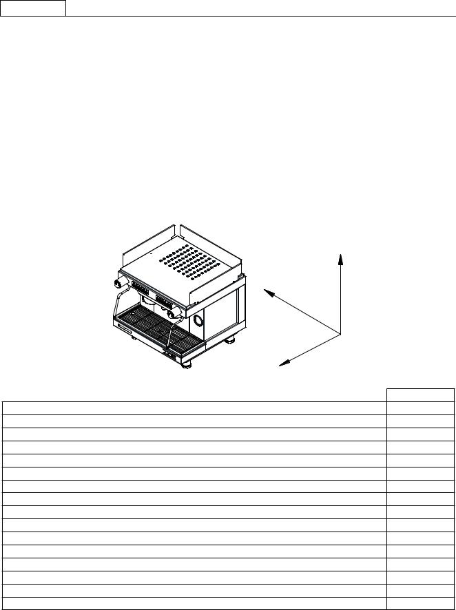
CARATTERISTICHE TECNICHE
Z 
X
|
Y |
|
|
GRUPPI |
2 |
Larghezza (X) |
mm |
530 |
Profondità (Y) |
mm |
528 |
Altezza (Z) |
mm |
543 |
Capacità |
litri |
7 |
Peso netto |
Kg |
45 |
Peso lordo |
Kg |
51 |
Tensione di alimentazione |
V |
220-240 1N~ |
Potenza assorbita dalla resistenza (230V) |
kW |
2,5 |
Potenza assorbita dalla resistenza scaldatazze (optional) |
kW |
0,060 |
Potenza assorbita dall‘elettropompa |
kW |
0,2 |
Potenza assorbita dall‘elettropompa esterna |
kW |
0,2 |
Potenza assorbita dalle elettrovalvole |
kW |
0,0225 |
Potenza assorbita dal regolatore autom. Di livello |
kW |
0,01 |
Pressione di esercizio caldaia |
(0,8-1 Bar) MPa |
0,08:0,1 |
Pressione acqua rete idrica (max) |
(6 Bar) MPa |
0,6 |
Pressione di erogazione caffè |
(8-9 Bar) MPa |
0,8/0,9 |
Il livello di pressione sonora ponderato A della macchina è inferiore a 70dB.
Per il corretto funzionamento e la buona manutenzione della macchina, si consiglia di seguire attentamente il presente manuale attenendosi alle norme indicate e facendo riferimento agli schemi riportati all’interno.
4
ITALIANO
INSTALLAZIONE
Prima di installare la macchina, accertarsi che il voltaggio e la potenza della rete siano adeguati ai dati riportati nella tabella delle caratteristiche tecniche. Togliere quindi la macchina dall’imballo e collocarla in modo stabile e sicuro nel luogo destinatole, accertandosi che vi sia lo spazio necessario per l’utilizzo della stessa.
Posizionare la macchina ad un altezza da terra alla griglia superiore di 1,5Mt.
ALLACCIAMENTO ELETTRICO
Collegare il cavo di alimentazione (G) alla presa.
N.B. VERIFICARE CHE I DATI DI TARGA SIANO CONFORMI ALLA LINEA DI ALIMENTAZIONE.
COLLEGAMENTO IDRAULICO
Al momento dell’installazione la caldaia e gli scambiatori sono a secco, per evitare che un eventuale congelamento crei danni all’apparecchio.
1)Le macchine devono essere alimentate solo con acqua fredda.
2)Se la pressione di rete è superiore ai 0,6 Mpa (6 bar) diventa indispensabile l’installazione di un riduttore di pressione da regolare in uscita ad un massimo di 0,6 Mpa (6 bar).
3)Collegare il tubo di scarico alla vaschetta evitando curve troppo strette e cercando di mantenere una pendenza sufficiente al deflusso dell’acqua di scarico.
4)Collegare il tubo flessibile da 3/8” alla rete idrica e successivamente all’addolcitore ed alla macchina.
Per il collegamento alla rete di alimentazione dell’acqua vanno rispettati gli eventuali regolamenti nazionali.
N.B. L’addolcitore è un componente indispensabile per il corretto funzionamento della macchina, per l’ottenimento di un’ottima resa del caffè in tazza e per una lunga durata della componentistica in quanto ha la capacità di depurare l’acqua dal calcare e dai residui che altrimenti comprometterebbero la vita della stessa.
La ditta declina ogni responsabilità nel caso non vengano rispettate le suddette norme.
Prima di collegare il tubo all’entrata della pompa, aprire il rubinetto e far circolare acqua per circa 2 min attraverso l’addolcitore per eliminare eventuali residui di sporco depositati nel circuito.
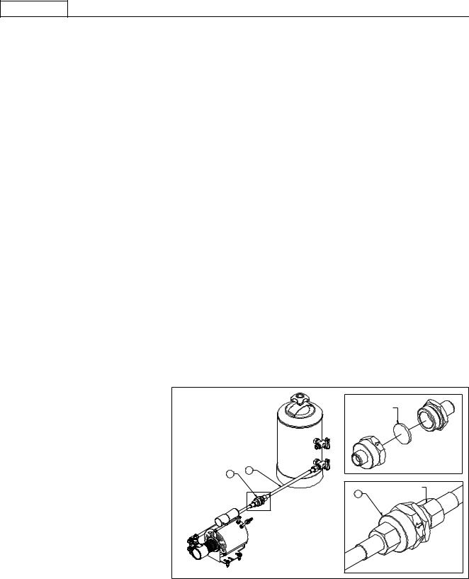
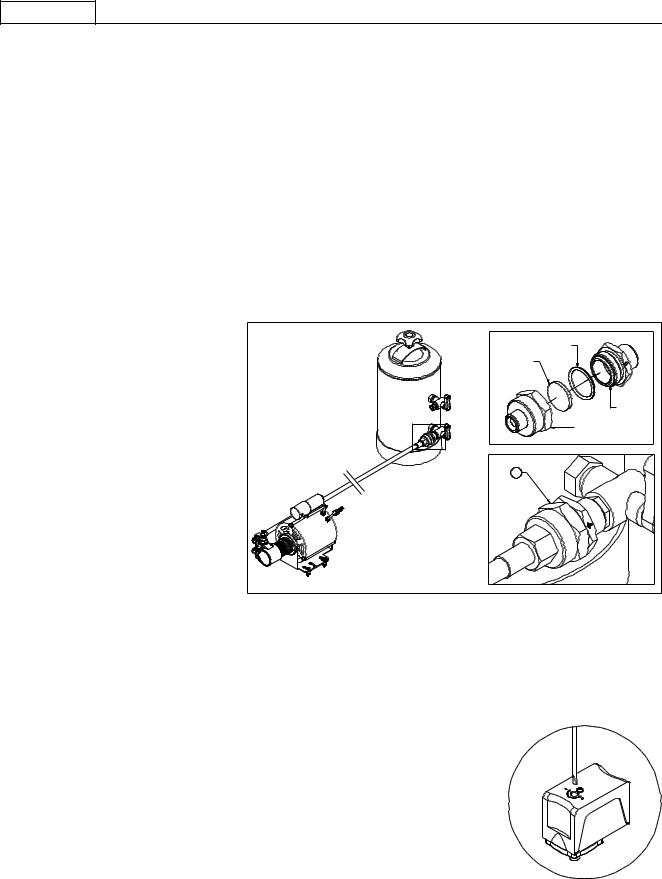
FILTRO IMPURITÀ
Il filtro impurità (cod.10355150) viene nor-
malmente montato sul tubo che collega il depuratore al pompante (fig.A) per impedire che le impurità presenti nell’acqua possano danneggiare congegni montati a valle quali po mpante,volumetrici,elettrovalvole,ecc.
Il filtro a pastiglia (cod.10355162) che blocca le impurità presenti nell’acqua va sostituito
orientativamente ogni 3 mesi. E’ chiaro che i 3 mesi sono un periodo indicativo che deve essere in realtà correlato al consumo d’acqua ed alle impurità presenti nella rete idrica.
Per sostituire il filtro a pastiglia: svitare il filtro impurità (cod.10355150) e sostituire il filtro
a pastiglia.
Prima di montare il nuovo filtro a pastiglia accertarsi che l’interno del corpo (10355152 e
10355154) sia completamente pulito. Even-
tuali corpi estranei dovranno essere rimossi per assicurare una corretta filtrazione.
Il filtro impurità deve essere montato secondo la direzione del flusso indicato dalla freccia (fig.A). rilevabile sul corpo.
USO
CONTROLLO PRELIMINARE
Prima di utilizzare la macchina accertarsi che:
-L’alimentazione sia inserita correttamente.
-Il tubo di carico sia correttamente collegato alla rete, che non vi siano perdite e che l’acqua sia aperta.
-Il tubo di scarico sia posizionato secondo le precedenti istruzioni e fissato mediante fascetta stringi tubo.
Tenuto aperto un rubinetto vapore (B), portare l’interruttore generale (D) nella posizione 1 ed attendere che l’acqua, all’interno della caldaia, raggiunga il livello massimo prestabilito dal controllo elettronico; se il riempimento della caldaia non avviene entro il time-
5
ITALIANO
out impostato (90 sec.), la pompa si stoppa e cominciano a lampeggiare i led delle pulsantiere. A questo punto si deve portare l’interruttore generale (D) nella posizione 0 e successivamente nella posizione 1 per terminare il riempimento della caldaia.
Portare quindi l’interruttore generale (D) in posizione 2: in tal modo sarà attivata l’alimentazione delle resistenze elettriche che inizieranno a scaldare l’acqua.
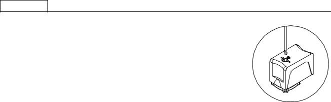
Attendere che cominci a fuoriuscire del vapore dal vaporizzatore (B), quindi chiudere il rubinetto e controllare, tramite il manometro Caldaia, che la pressione si porti e si mantenga ad un valore pari a 0,8:1 bar. In caso contrario si dovrà agire sulla vite interna di regolazione del pressostato tramite un cacciavite (+aumenta, - diminuisce vedi figura a lato).
EROGAZIONE ACQUA CALDA
Accertarsi che il manometro di caldaia indichi una pressione di 0,5:1 bar.
Premere il pulsante (M6) per l’erogazione dell’acqua calda e premere nuovamente lo stesso per fermarla.
Si ricorda di prestare le massima attenzione onde evitare ustioni.
EROGAZIONE VAPORE
Fatta eccezione per la macchina ad un gruppo che ne possiede uno solo, su tutti gli altri modelli sono presenti n° 2 vaporizzatori posti ai lati del piano di manovra. Tali vaporizzatori sono rientranti e orientabili perché dotati di snodo sferico. Per l’erogazione del vapore è sufficiente ruotare le manopole (B) in senso antiorario. Si ricorda di prestare la massima attenzione onde evitare ustioni.
EROGAZIONE CAFFÈ MOD. ZOE COMPACT SAP
Inserire il portafiltro (E) nell’apposita sede (F) ruotandolo in senso antiorario. Premere il tasto (M5) e, dopo aver atteso che la quantità di caffè sia quella desiderata, ripremerlo.
EROGAZIONE CAFFÈ MOD. ZOE COMPACT SED
Inserire il portafiltro (E) nell’apposita sede (F) ruotandolo in senso antiorario. Selezionare sulla tastiera (M) la didascalia corrispondente al tipo di erogazione desiderata:
M1=Erogazione di un caffè ristretto/normale. M2=Erogazione di un caffè normale/lungo. M3=Erogazione di due caffè ristretti/normali. M4=Erogazione di due caffè normali/lunghi.
M5=Tasto di programmazione elettronica o erogazione manuale continua.
PROGRAMMAZIONE DOSI
a)Si accede a questa fase tenendo premuto per oltre 5 secondi il tasto M5 della prima pulsantiera a sinistra. I led dei tasti M5 cominceranno a lampeggiare continuamente. Scegliere la didascalia corrispondente alla dosatura desiderata e premere per erogare. Rimangono accesi contemporaneamente il tasto M5 e quello della dosatura prescelta. Raggiunta la dose desiderata ripremere il tasto dosatura prescelto in modo da permettere alla centralina di memorizzare i dati. Ripetere l’operazione suddetta per tutte le 4 dosature della pulsantiera. È possibile impostare una dosatura anche per il tasto di prelievo acqua calda (M6) ripetendo la suddetta operazione. Al termine dell’operazione la dosatura memorizzata verrà automaticamente utilizzata anche dai restanti gruppi. Gli altri gruppi si possono comunque programmare indipendentemente ripetendo le stesse operazioni effettuate in precedenza solo dopo aver programmato il primo gruppo di sinistra.
b)Sono presenti, all’interno della centralina 2 sistemi di sicurezza volti a preservare il sistema elettronico e varie componenti della macchina. Se premendo un tasto relativo ad una dosatura di caffè dovesse verificarsi un lampeggiamento da parte del led corrispondente, questo segnalerebbe un’anomalia nel sistema elettronico o la mancanza di alimentazione idrica. È previsto, per motivi di sicurezza, che l’erogazione dell’acqua si arresti dopo 4 minuti e, comunque, non oltre l’uscita di 4 litri d’acqua.
c)L’elettronica ZOE COMPACT SED ha anche la possibilità di riprodurre l’effetto di preinfusione bagnando per 0.6 secondi il caffè e bloccando successivamente l’infusione per 1.2 secondi. Questo optional si può applicare solo per le dosi singole.
PER ABILITARE LA PREINFUSIONE
A macchina spenta, portare l’interruttore generale (D) nella posizione 1 e contemporaneamente tenere premuto il tasto (M1) sul gruppo di sinistra finche il led corrispondente al tasto (M5) rimane acceso; poi rilasciare il tasto (M1). A questo punto portare l’interruttore generale (D) nella posizione 0 e successivamente nella posizione 2 per memorizzare l’operazione.
PER DISABILITARE LA PREINFUSIONE
A macchina spenta, portare l’interruttore generale (D) nella posizione 1 e contemporaneamente tenere premuto il tasto (M2) sul gruppo di sinistra finche il led corrispondente al tasto (M5) rimane acceso; poi rilasciare il tasto (M2). A questo punto spegnere e poi riaccendere la macchina con l’interruttore generale (D) per memorizzare l’operazione.
PULIZIA
Filtro gruppo erogazione: dopo aver erogato l’ultimo caffè il filtro ed il portafiltro dovranno essere puliti con acqua. Nel caso che
6

ITALIANO
risultino deteriorati o intasati sarà necessario sostituirli.
Vaschetta di scarico e griglia: la griglia ed il piatto di scarico vanno spesso rimossi dalla propria sede per essere puliti da residui di caffè.
Far scorrere l’acqua calda e pulire la vaschetta di scarico dai residui di caffè che si vanno a depositare sul fondo per evitare fermentazioni che potrebbero generare cattivi odori.
Impianto di depurazione dell’acqua: l’addolcitore va periodicamente rigenerato secondo le modalità stabilite dal costruttore e riportate nel libretto di istruzioni.
Carrozzeria esterna: la carrozzeria esterna e le parti in acciaio vanno pulite con spugne e panni morbidi per evitare graffiature. Si raccomanda di utilizzare detersivi non contenenti polveri abrasive, solventi o lana d’acciaio.
AVVERTENZE: si consiglia, durante l’utilizzo della macchina, di tenere sotto controllo i vari strumenti verificandone le normali condizioni già precedentemente esposte.
MANCATO FUNZIONAMENTO DELLA MACCHINA
L’utente dovrà accertarsi che non sia dovuto a:
-Mancanza di alimentazione elettrica
-Mancanza d’acqua dalla rete o all’interno della caldaia.
Per altre cause rivolgersi ad un Centro di Assistenza SANREMO qualificato.
PRIMA DI EFFETTUARE QUALSIASI OPERAZIONE ALL’INTERNO DELLA MACCHINA O COMUNQUE DI RIMUOVERE UNA PARTE DELLA CARROZZERIA, SCOLLEGARE SEMPRE LA CORRENTE ELETTRICA.
GARANZIA
Ogni macchina acquistata (conservare scontrino fiscale, fattura, bolla di consegna) è coperta dalla garanzia di legge: questa prevede la sostituzione gratuita delle parti con difetti di fabbricazione purché accertati dal servizio di assistenza o dal produttore, e sempre che la macchina non sia stata impropriamente utilizzata o manomessa da persone non autorizzate o comunque usando componenti o tecniche non corrette.
La parte eventualmente difettosa va resa al produttore.
NB = Si raccomanda di non far funzionare per nessun motivo la pompa di carico a secco (cioè senza acqua) perché la pompa si surriscalda e si rovina, da cui ne deriva che la suddetta non viene sostituita in garanzia.
La pompa con questo uso anomalo non è sostituita in garanzia.
AVVERTENZE
La pulizia della macchina non deve essere effettuata mediante getto d’acqua. Non immergere la macchina in acqua.
La macchina non dev’essere posta presso fonti di calore La macchina non è adatta per l’installazione all’esterno
I bambini devono essere sorvegliati per assicurarsi che non giochino con l’apparecchio.
L’apparecchio deve essere installato solo in luoghi dove il suo uso e mantenimento è limitato al personale qualificato.
L’accesso alla zona di servizio è limitata alle persone che hanno la conoscenza e l’esperienza pratica dell’apparecchio, specialmente quando si tratta di sicurezza e di igiene.
L’inclinazione della macchina, per un suo uso in sicurezza, deve essere in posizione orizzontale.
In caso di danneggiamento al cavo di alimentazione rivolgersi ad un Centro Assistenza SANREMO, poiché per la sua sostituzione è necessario un apposito utensile.
La macchina deve essere impiegata in ambienti a temperature comprese tra 5°C e 35°C.
IN CASO DI GUASTO O CATTIVO FUNZIONAMENTO, CI SI DEVE RIVOLGERE ESCLUSIVAMENTE A PERSONALE QUALIFICATO DEL SERVIZIO ASSISTENZA.
I dati e le caratteristiche indicate nel presente manuale non impegnano la ditta costruttrice che si riserva il diritto di apportare modifiche ai propri modelli in qualsiasi momento.
La ditta costruttrice inoltre non si assume alcuna responsabilità per danni a persone o cose derivanti dalla mancata osservazione delle norme riportate nel presente manuale.
7

ITALIANO
Nel caso di danneggiamentoai cavi rivolgersi ad un centro assistenza, poichè per la sostituzione
è necessario un apposito utensile
ADDOLCITORE
/
RETE IDRICA
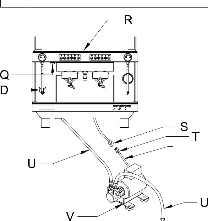
LEGENDA
D – INTERRUTTORE GENERALE 0 – SPENTO
1 – ACCENSIONE POMPA ED AUTOMATISMI
2 – ACCENSIONE POMPA , AUTOMATISMI E RISCALDAMENTO ELETTRICO Q – INTERRUTTORE ACCENSIONE / SPEGNIMENTO PER SCALDATAZZE
LUMINOSO = ACCESO NON LUMINOSO = SPENTO
R – RESISTENZA SCALDATAZZE
S – BLOCHETTO 3 VIE FEMMINA
T – BLOCCHETTO 3 VIE MASCHIO
U – TUBO TRAZIONE CARICO ACQUA
V – POMPA ESTERNA
Collegare la pompa esterna in maniera stabile sui piedini d’appoggio.
La pompa non deve essere posta vicino fonti di calore o acqua.
8
ITALIANO
Avvertenze per un corretto utilizzo delle pompe rotative
1) CORRETTO ALLINEAMENTO TRA POMPA E MOTORE
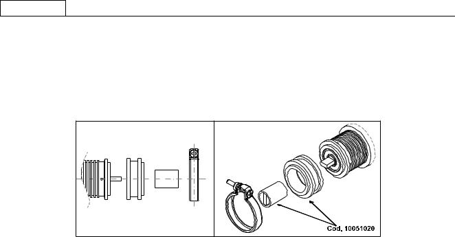
A volte la rumorosità del gruppo è causata proprio da un’allineamento imperfetto, infatti quando l’accoppiamento tra i due componenti è rigido, non sempre il rotore della pompa e quello del motore si trovano in asse. Il danno che più frequentemente si manifesta, se perdura questa condizione, è il bloccaggio della pompa. Per evitare questo problema è possibile intervenire efficacemente interponendo tra la pompa con attacco a fascetta ed il motore un giunto elastico, a questo proposito è disponibile come accessorio un kit ns. codice 10051020.
2) QUALITA’ DELL’ACQUA
Le tolleranze di lavorazione e i materiali utilizzati per le pompe rotative a palette sono tali da rendere necessaria una qualità dell’acqua il più possibile pulita e comunque priva di particelle in sospensione. Spesso la sabbia, le incrostazioni dei tubi di collegamento o le resine dell’addolcitore, quando passano nella pompa, rigano le parti in grafite provocando problemi di pressione e portata.
Consigliamo, laddove non vi sia la garanzia di acqua pulita all’interno di un circuito chiuso e quindi non “contaminabile” di inter - porre un filtro da 5 o 10 micron fra l’addolcitore e la pompa.
E’ importante inoltre tenere pulito il filtro. L’occlusione del filtro prima della pompa causa infatti cavitazione e provoca la rottura della pompa in tempi rapidi (vedi punto 4)
Nel caso si utilizzi un serbatoio di alimentazione, per evitare di aspirare eventuali sedimenti, consigliamo di posizionare il pescante qualche centimetro sopra il fondo.
3) FUNZIONAMENTO A SECCO
Le pompe rotative a palette sono in grado di funzionare a secco solo per brevi periodi di tempo (pochi secondi), in caso di funzionamento prolungato senz’acqua la tenuta, non essendo raffreddata adeguatamente, raggiunge temperature molto elevate fino alla rottura della stessa, la conseguenza più probabile è una perdita consistente visibile dai 4 forellini di drenaggio posizionati in pros - simità della fascetta. Nel caso di possibilità di mancanza d’acqua dalla rete, è consigliabile inserire un pressostato di minima prima della pompa, nel caso si utilizzi un serbatoio di alimentazione è consigliabile equipaggiarlo con un controllo di livello adeguato.
4) CAVITAZIONE
Questa situazione si manifesta quando il flusso d’acqua di alimentazione non è adeguato rispetto alle caratteristiche della pompa: filtri intasati, diametro delle tubazioni insufficienti o più utenze sulla stessa linea, rappresentano le cause più frequenti. L’apertura dell’elettrovalvola di sicurezza quando prevista (generalmente posizionata prima della pompa e dei filtri), deve avvenire, sempre per evitare cavitazione, in anticipo rispetto all’accensione della pompa. Per lo stesso motivo, quando la pompa finisce di erogare, la chiusura dell’elettro valvola deve essere ritardata.
L’aumento della rumorosità è il fenomeno più percettibile, se la condizione persiste, le conseguenze sono simili a quelle previste per il funzionamento a secco.
5) RITORNO D’ACQUA CALDA
A volte capita che la valvola di non ritorno, prevista sul circuito idraulico della macchina tra la pompa e la caldaia, sia difettosa. In questo caso la pompa potrebbe rimanere a contatto con acqua calda (90/ 100°c.) e rovinarsi a causa dalle diverse dilatazioni dei materiali impiegati, il bloccaggio è la conseguenza più diffusa.
6) CONNESSIONI NON IDONEE
Le pompe possono avere raccordi 3/8” NPT (conici) o GAS (cilindrici), talvolta vengono utilizzati bocchettoni e nippli con filettature diverse da quelle consigliate delegando al sigillante o al teflon una tenuta fatta solo con pochi giri di filetto. Se il raccordo viene forzato c’è il rischio di produrre un truciolo, se si utilizza troppo sigillante c’è la possibilità che l’eccedenza entri nella pompa, in entrambi i casi è possibile provocare danni.
7) COLPI D’ARIETE
L’apertura dell’elettrovalvola, se prevista dopo la mandata della pompa, deve avvenire, per evitare colpi d’ariete, in anticipo rispetto all’accensione della pompa. Per lo stesso motivo, quando la pompa finisce di erogare, la chiusura dell’elettrovalvola deve essere ritardata.
Il colpo d’ariete può provocare la rottura dei supporti in grafite e danneggiare la tenuta meccanica provocando il bloccaggio della pompa e perdita di liquido.
9

ITALIANO
8) MANIPOLAZIONE
La caduta accidentale della pompa può causare delle ammaccature e delle deformazioni tali da compromettere delicate tolleranze interne, per lo stesso motivo è necessario porre la massima attenzione quando la pompa viene fissata in morsa per il montaggio o lo smontaggio dei raccordi.
9) INCROSTAZIONI DI CALCARE
Nel caso in cui l’acqua pompata sia particolarmente calcarea e non sia pretrattata con resine a scambio ionico o altri sistemi efficaci, è possibile che all’interno della pompa si formino delle incrostazioni.
L’utilizzo del by-pass come regolatore di portata accelera questo fenomeno, maggiore è il ricircolo di acqua e più il processo è rapido.
Le incrostazioni possono causare un progressivo indurimento della pompa e in alcuni casi il bloccaggio o una riduzione di pressione dovuta a una non corretta modulazione del by-pass.
Per limitare il problema è consigliabile usare pompe con portate adeguate al circuito idraulico della macchina. In alcuni casi potrebbe essere utile effettuare periodicamente un trattamento disincrostante con appositi acidi.
INFORMAZIONE AGLI UTENTI
Ai sensi dell’art. 13 del Decreto legislativo 25 luglio 2005, n. 151 “Attuazione delle Direttive 2002/95/CE,2002/96/CE e 2003/108/CE, relative alla riduzione dell’ uso di sostanze pericolose nelle apparecchiature elettriche ed elettroniche, nonché allo smaltimento dei rifiuti”.
Il simbolo del cassonetto barrato riportato sull’apparecchiatura o sulla sua confezione indica che il prodotto alla fine della propria vita utile deve essere raccolto separatamente dagli altri rifiuti.
La raccolta differenziata della presente apparecchiatura giunta a fine vita è organizzata e gestita dal produttore.
L’utente che vorrà disfarsi della presente apparecchiatura dovrà quindi contattare il produttore e seguire il sistema che questo ha adottato per consentire la raccolta separata dell’apparecchiatura giunta a fine vita.
L’adeguata raccolta differenziata per l’avvio successivo dell’apparecchiatura dismessa al riciclaggio, al trattamento e allo smaltimento ambientale compatibile contribuisce ad evitare possibili effetti negativi sull’ambiente e sulla salute e favorisce il reimpiego e/o riciclo dei materiali di cui è composta l’apparecchiatura.
Lo smaltimento abusivo del prodotto da parte del detentore comporta l’applicazione delle sanzioni amministrative previste dalla normativa vigente.
10
ITALIANO
MOD. ZOE COMPACT 2GR SED / SAP
B – Manopola rubinetto vapore |
M1 |
– Erogazione di una dose corta di caffè |
|
C – Erogatore acqua |
M2 |
– Erogazione di una dose lunga di caffè |
|
D – Interruttore generale |
M3 |
– Erogazione di due dosi corte di caffè |
|
0 |
– Spento |
M4 |
– Erogazione di due dosi lunghe di caffè |
1 |
– Accensione pompa ed automatismi |
M5 |
– Erogazione continua e tasto programmazione |
2 |
– Accensione pompa, automatismi e riscaldamento elettrico |
M6 |
– Erogazione acqua calda |
E – Portafiltro |
N – Manometro pressione pompa |
||
F – Gruppo inserimento portafiltro |
P – Manometro pressione caldaia |
||
G – Cavo alimentazione |
T – Interrutore per scaldatazze (optional) |
||
11

ITALIANO
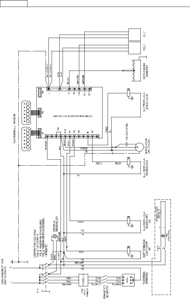
SCHEMA ELETTRICO MONOFASE ZOE COMPACT 2GR SAP Agg.07/13
12 |
ITALIANO
SCHEMA ELETTRICO MONOFASE ZOE COMPACT 2GR SED Agg.07/13
13 |
ITALIANO
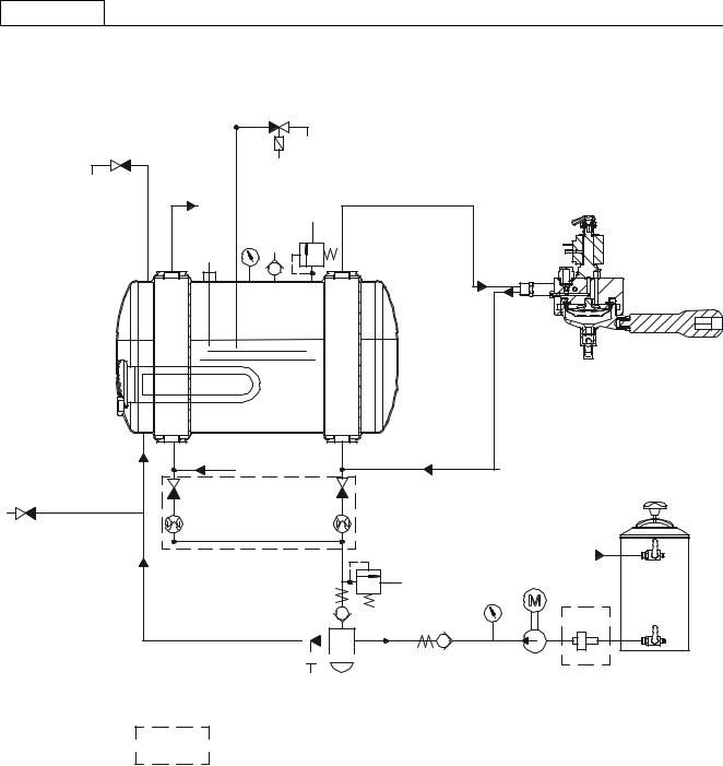
SCHEMA IDRAULICO ZOE COMPACT 2GR AGG. 07/2013
21
20
19 |
18 |
17 |
|
35 |
|||
23 |
|
||
|
|
34 |
|
|
|
14 |
|
|
|
36 |
16 |
15 |
13 |
12 |
12 |
2 |
|
11 |
11 |
1 |
3 |
|
|
6 |
M |
|
|
10 |
7 |
|
|
4 |
|
|
5 |
38 |

 8 9
8 9 


Varianti
LEGENDA SCHEMA IDRAULICO ZOE COMPACT 2GR SED - SAP |
|
|
||
1 |
Alimentazione rete idrica |
15 |
Scambiatore |
|
2 |
Addolcitore |
16 |
Resistenza caldaia |
|
3 |
Rubinetto entrata acqua |
17 |
Valvola di sicurezza |
|
4 |
Rubinetto uscita acqua |
18 |
Valvola antivuoto |
|
5 |
Pompa e motore elettrico |
19 |
Manometro (pressione caldaia) |
|
6 |
Manometro (pressione pompa) |
20 |
Rubinetto prelievo vapore |
|
7 |
Valvola di non ritorno |
21 |
Elettrovalvola prelievo acqua calda |
|
8 |
Massello di carico con filtro |
23 |
Sonda di livello |
|
9 |
Elettrovalvola per riempimento automatico |
26 |
Pressostato |
|
10 |
Valvola di espansione |
34 |
Gruppo |
|
11 |
Contatore volumetrico |
35 |
Elettrovalvola gruppo erogatore |
|
12 |
Rubinetto carico |
36 |
Portafiltro |
|
13 |
Rubinetto scarico caldaia |
38 |
Filtro |
|
14 |
Caldaia |
|
|
|
14

ITALIANO
15
ESPLOSO ZOE COMPACT 2GR SED SAP – Agg. 07-13

ITALIANO
LEGENDA ESPLOSO ZOE COMPACT AGG.07-13
POS. |
COD. |
DESCRIZIONE |
1A |
10017732 |
TELAIO ZOE 2 CMPT NERO OPACO |
1B |
10017734 |
TELAIO ZOE 2 CMPT BIANCO |
2A |
10017782 |
PANNELLO DX ZOE 2 CMPT NERO LUCIDO |
2B |
10017784 |
PANNELLO DX ZOE 2 CMPT ROSSO |
2C |
10017786A |
PANNELLO DX ZOE 2 CMPT VIOLA |
2D |
10017788 |
PANNELLO DX ZOE 2 CMPT NERO OPACO |
2E |
10017790 |
PANNELLO DX ZOE 2 CMPT BIANCO PERLA |
|
|
|
2F |
10017792 |
PANNELLO DX ZOE 2 CMPT GIALLO |
2G |
10017794 |
PANNELLO DX ZOE 2 CMPT VERDE |
3A |
10017802 |
PANNELLO SX ZOE 2 CMPT NERO LUCIDO |
3B |
10017804 |
PANNELLO SX ZOE 2 CMPT ROSSO |
3C |
10017806A |
PANNELLO SX ZOE 2 CMPT VIOLA |
3D |
10017808 |
PANNELLO SX ZOE 2 CMPT NERO OPACO |
3E |
10017810 |
PANNELLO SX ZOE 2 CMPT BIANCO PERLA |
3F |
10017812 |
PANNELLO SX ZOE 2 CMPT GIALLO |
3G |
10017814 |
PANNELLO SX ZOE 2 CMPT VERDE |
4 |
10352434 |
FERMATAZZE DX/SX ZOE 2 CMPT TRASP. |
5A |
10017632 |
PANNELLO POST. ZOE 1 NERO LUCIDO |
5B |
10017634 |
PANNELLO POST. ZOE 1 ROSSO |
5C |
10017636A |
PANNELLO POST. ZOE 1 VIOLA |
5D |
10017638 |
PANNELLO POST. ZOE 1 NERO OPACO |
5E |
10017640 |
PANNELLO POST. ZOE 1 BIANCO PERLA |
5F |
10017642 |
PANNELLO POST. ZOE 1 GIALLO |
5G |
10017644 |
PANNELLO POST. ZOE 1 VERDE |
6 |
10352436 |
FERMATAZZE POST. ZOE 2 CMPT TRASP. |
8 |
10017752A |
GRIGLIA SUP. ZOE 2 CMPT |
9 |
10805027 |
VITE TBLM4X10 A2 |
10A |
10017762 |
PROTEZ. GR. ZOE 2 CMPT NERO LUCIDO |
10B |
10017764 |
PROTEZ. GR. ZOE 2 CMPT ROSSO |
10C |
10017766A |
PROTEZ. GR. ZOE 2 CMPT VIOLA |
10D |
10017768 |
PROTEZ. GR. ZOE 2 CMPT NERO OPACO |
10E |
10017770 |
PROTEZ. GR. ZOE 2 CMPT BIANCO PERLA |
10F |
10017772 |
PROTEZ. GR. ZOE 2 CMPT GIALLO |
10G |
10017774 |
PROTEZ. GR. ZOE 2 CMPT VERDE |
11 |
10017628 |
GRIGLIA SCARICO ZOE 1 |
12 |
10017622 |
PIATTO DI SCARICO ZOE 1 |
13A |
10017712A |
FRONTALINO INF. ZOE 1 NERO OPACO |
13B |
10017714A |
FRONTALINO INF. ZOE 1 BIANCO |
14 |
10017750 |
PROTEZIONE FRONT. ZOE 2 CMPT S/MAN. |
15 |
10352065 |
PIEDINO D50X55 INOX TELESCOPICO |
16 |
10012144 |
ROMPIGETTO PER VASCHETTA SCARICO |
17 |
10022441A |
VASCHETTA SCARICO C/RESCA D14 |
18 |
10806099 |
FASCETTA INOX STRINGITUBO |
19 |
10455084 |
RESISTENZA 2500W 230V 2GR CMPT |
20 |
10502020 |
RONDELLA PTFE D56X41X2mm |
21 |
10002722 |
CALDAIA RAME 2GR D180 7LITRI CMPT |
22 |
10252098A |
MOTORE EL.130W 230V CB 1-2GR INTERNA |
23 |
10255022 |
ANTIVIBRANTE PUFFER |
24 |
10252062 |
POMPA COMPACT 70L/H |
25 |
10602004 |
PRESSOSTATO MONOFASE |
26A |
10112072E |
CENTRALINA XLC SED 1-2-3GR 230V |
26B |
10112113 |
CENTRALINA XLC SAP 1-2-3GR PER ZOE/TO |
27 |
10303093A |
ELETTR. 2VIE BAS.32X32 230V |
28 |
10112282 |
CONTATORE VOLUMETRICO 1/4" ATT.OGIVA |
29 |
10122050 |
COMMUTATORE MONOFASE |
30 |
10051990A |
GRUPPO ANELLO ATT.OGIVA |
31 |
10302066 |
ELETTROV. 3VIE BAS.32X32 230V |
32 |
10553021 |
SPIA ARANCIO D6 230V CABLATA |
33A |
10102640 |
CABLAGGIO ZOE 2 CMPT SED |
33B |
10102644 |
CABLAGGIO ZOE 2 CMPT SAP |
34 |
10552015 |
MANOMETRO DOPPIA SCALA ROMA |
35 |
10003324 |
TUBO USCITA ACQUA CALDA ZOE 2 CMPT |
36 |
10859036 |
RIDUZIONE 1/8"M 3/8"M |
37 |
10402056A |
OR 2062 VITON |
38 |
10402043 |
MOLLA SNODO |
39 |
10402054 |
SCODELLINO SNODO |
40 |
10402082 |
OR SNODO LANCIA D10 |
41 |
10402282 |
DADO LANCIA VAPORE MLX |
42 |
10402288 |
SNODO A SFERA LANCIA MLX |
43 |
10402274 |
TUBO VAP.BRILL.INOX LANCIA VAP.RM |
44 |
10753052 |
GOMMINO ANTISCOTTURA |
45A |
10402276 |
TROMBONCINO INOX 2 FORI LATERALI |
45B |
10402279 |
TROMBONCINO INOX 4 FORI |
46 |
10402081 |
OR TUBO LANCIA MLX |
47 |
10402266 |
SNODO A SFERA INOX ACQUA 1/8"M |
48 |
10505018 |
OR D.7,2X1,9 EPDM OR6 DOCCIA ACQUA |
49 |
10402140 |
DOCCIA EROGAZIONE |
50 |
10402143 |
DOCCIA CORTA EROGAZ. ACQUA COMPL. |
51 |
10853085 |
DADO ESAGONALE 1/8" |
52 |
10402120A |
CORPO RUBINETTO |
53 |
10505561 |
BUSSOLA RAME RUBINETTO |
54 |
10505121 |
OR NBR ASTA RUBINETTO |
55 |
10402015 |
BUSSOLA ASTA RUBINETTO |
56 |
10402014 |
MOLLA ASTA RUBINETTO |
57 |
10402061 |
ASTA CENTRALE RUBINETTO |
58 |
10505558 |
GUARNIZ. TENUTA ASTA RUBINETTO |
59 |
10803547 |
RONDELLA D20 ZN PIANA |
60 |
10806312 |
RONDELLA D21 DENT. ZN |
61 |
10092164A |
MANOPOLA VAPORE ROMA |
62 |
10806370B |
COPPIGLIA RUBINETTO |
63 |
10092162B |
TAPPO MANOPOLA VAPORE ROMA |
64 |
10402040 |
RONDELLA OTT. RUBINETTO |
65 |
10402028 |
MEZZO DADO 1/2" RIALZATO CR. |
66 |
10303086 |
ELETTR. 2VIE 1/8"230V |
67 |
10402284 |
LANCIA VAPORE COMPLETA RM |
69 |
10402310C |
ASS.PORTAFILTRO 1 TAZZA 1,3 |
70 |
10402312B |
ASS.PORTAFILTRO 2 TAZZE 1,3 |
71 |
10052085 |
BECCUCCIO 2 VIE APERTO |
72 |
10091150A |
MANOPOLA PORTAFILTRO VR-RM |
73 |
10052034 |
CORPO PORTA FILTRO |
74 |
10052055 |
MOLLA FERMA FILTRO 1,3 |
75A |
10052100 |
FILTRO 1 TAZZA |
75B |
10052101 |
FILTRO 1 TAZZA 6GR MOD. CIALDE |
76 |
10052110 |
FILTRO 2 TAZZE |
77 |
10052220 |
FILTRO CIECO |
78 |
10052075 |
BECCUCCIO 1 VIA APERTO |
79 |
10051992 |
ASS. GRUPPO ANELLO 230V ATT.OGIVA |
80 |
10255028A |
RACCORDO GOMITO GIR.F1/8 |
81 |
10852050A |
1050 8-1/8"M RACCORDO DRITTO |
82 |
10091154 |
ANELLO MANICO PORTAFILTRO VR-RM |
83 |
10058040 |
CORPO MASSELLO LIGTH |
84 |
10091152 |
TAPPO MANICO PORTAFILTRO VR-RM |
85 |
10355172 |
FILTRO RETE TONDO |
86 |
10056058B |
ASS.CORPO MASSELLO LIGHT |
87 |
10655557 |
VALVOLA ESPANSIONE |
88 |
10652052 |
VALVOLA ANTIRIFLUSSO |
89 |
10806288 |
ANELLO SEEGER MASSELLO LIGTH |
90 |
10255058 |
RACCORDO GOMITO GIREVOLE 1/8M |
91 |
10058050 |
RONDELLA RAME 1/4" MASSELLO LIGHT |
92 |
10058044 |
RACCORDO 1/4-1/4 MASSELLO LIGHT |
93 |
10105012 |
PASSACAVO ANTISTRAPPO |
94 |
10402068 |
OR 106 NBR |
95 |
10805071 |
VITE TCEI M4X10 A2 |
96 |
10502070A |
OR 3187 EPDM FDA |
97 |
10052248 |
MAZZOCCO GRUPPO ANELLO X GUARN. E DOCC. E61 |
98 |
10052141 |
DIFFUSORE GRUPPO E61 |
99 |
10052120 |
DOCCETTA A RETE GRUPPO E61 |
16

ITALIANO
100 |
10502110 |
GUARN. SOTTOC. GRUPPO E61 |
101 |
10052142 |
TAPPO CHIUS. GIGLEUR GR.ANELLO |
102 |
10052143 |
GUARN. TAPPO SUP. GR. ANELLO |
103 |
10052135 |
GIGLEUR GRUPPI FORO D.0,8 |
105 |
10052136 |
FILTRO GRUPPO E-61/ANELLO |
106 |
10805078 |
VITE TCEI M6X8 A2 |
107 |
10111082A |
TERMOSTATO 145° MONOFASE RIARMO MANUALE |
108 |
10805592 |
DADO M10X1 ZN |
110 |
10805116 |
VITE TC+ M3X10 NERA COMMUTATORE |
111 |
10122015 |
MANOPOLA PER COMMUTATORE |
112 |
10105180 |
BLOCCHETTO 2 VIE M. |
113 |
10058027 |
PISTONCINO MASSELLO VR |
114 |
10401400 |
RUBINETTO A SFERA 1/4"M/F |
115 |
10853092 |
RACCORDO DRITTO PORTAGOMMA 1/4" |
116 |
10022476B |
COPERCHIO VASCHETTA SCARICO |
117 |
10053110 |
MOLLA VALVOLA MASSELLO VR |
118 |
10058042 |
NIPLESS VALVOLA MASSELLO LIGTH |
119 |
10905010 |
TUBO SILICONE TRASP. |
120 |
10105136 |
CAVO ALIMENTAZIONE 3X1,5 |
121 |
10803519 |
RONDELLA D4,2 DENT.ZN |
122 |
10805512 |
DADO 4MA MEDIO ZN |
123 |
10852594 |
TUBO TRAZIONE 3/8F-3/8NIPLESS L.2000 |
124 |
10852596 |
TUBO TRAZIONE 1/4F-3/8NIPLESS L.400 |
125 |
10053109 |
RONDELLA RAME VALVOLA MASSELLO VR |
126 |
10058048 |
RONDELLA RAME 1/8" MASSELLO LIGHT |
127A |
10112268 |
PULSANTIERA TO 6 TASTI SED |
127B |
10112274 |
PULSANTIERA TO 2 TASTI SAP |
128A |
10112073 |
CAVO PIN TO PIN 900mm |
128B |
10112079 |
CAVO PIN TO PIN 800mm |
129 |
10556041A |
INTERRUTTORE ROSSO SCALDATAZZE |
130 |
10852460 |
TUBO SPIRALATO SCARICO L.2 MT |
131A |
10017412 |
SUPPORTO PULSANTIERA SED ZOE NERO |
131B |
10017414 |
SUPPORTO PULSANTIERA SED ZOE BIANCO |
131C |
10017432 |
SUPPORTO PULSANTIERA SAP ZOE NERO |
131D |
10017434 |
SUPPORTO PULSANTIERA SAP ZOE BIANCO |
132 |
10022489A |
VASCHETTA VALVOLA SICUREZZA D14 |
133 |
10105030 |
PASSACAVO IN GOMMA NERO |
137 |
10112064 |
SONDA LIVELLO 120MM |
138 |
10652040A |
VALVOLA DI SFIATO CALDAIA |
139 |
10852214 |
RONDELLA RAME HOV 1/4" |
140 |
10003302 |
PESCANTE ZOE CMPT |
141 |
10106060 |
PONTE OTTONE RESISTENZA |
142 |
10652012B |
VALVOLA SICUREZZA |
143A |
10052174 |
GIGLEUR FORO D2,5 |
143B |
10052176 |
GIGLEUR FORO D3 |
143C |
10052178 |
GIGLEUR FORO D3,5 |
143D |
10052179 |
GIGLEUR FORO D2 |
144 |
10852212 |
RONDELLA RAME HOV 3/8" |
146 |
10852060A |
1020 8-1/4"M RACC.GOMITO |
150 |
10853298A |
RACC. SCAMBIATORE INF. 1/4"-3/8"-3/8" |
152 |
10042046 |
INIETTORE PTFE D.8 1/4-1/8 |
153 |
10955033 |
ETICHETTA CAVO 220/240V |
154 |
10806286 |
ANELLO SEEGER A52X2 A2 |
155 |
10455100B |
PROTEZIONE RESISTENZA |
156 |
10803344 |
VITE TSP+ M4X10 A2 |
157 |
10805074 |
VITE TE M4X8 ZN |
158 |
10805027A |
VITE TBL+ M4x10 A2 |
159 |
10809011 |
DADO 4MA FLANGIATO |
160 |
10805182A |
VITE TSP+ M4X20 A2 |
161 |
10405540 |
PRESSORE A SFERA |
162 |
10017492 |
PIASTRA ANTISTRISCIAMENTO |
163 |
10806050 |
DADO M4 X RESISTENZA |
164 |
10952051B |
TARGHETTA ALL.SAN REMO 230V |
165 |
10805950 |
RIVETTO D3x6 A STRAPPO |
166A |
10955020A |
ETICHETTA SR 101X16,5 ANOD./ROSSA |
166B |
10955162 |
ETICHETTA SR 101X16,5 LUC./NERA |
166C |
10955172 |
ETICHETTA SR 101X16,5 LUC./BIANCA |
167 |
10955013A |
ETICHETTA TRIANGOLO SUPER.CALDA |
168 |
10955025A |
ETICHETTA TRIANGOLO TERRA |
169 |
10955015 |
ETICHETTA TRIANGOLO TENSIONE |
170 |
10805038 |
VITE TSP+ M3X6 A2 |
171 |
10809012 |
DADO 6MA FLANGIATO |
172 |
10803536 |
RONDELLA D6,2 DENT.ZN |
173 |
10805075 |
VITE TE M5X8 ZN |
174 |
10803520 |
RONDELLA D5,3 DENT.ZN |
175 |
10252038 |
CONDENSATORE MOTORE 150W |
176 |
10105243B |
CAPPUCCIO INTERRUTTORE TRASP. |
177 |
10003312 |
TUBO SCAMBIATORE SUP.ZOE 2 CMPT |
178 |
10003310 |
TUBO SCAMBIATORE INF.ZOE 2 CMPT |
179 |
10003320 |
TUBO VAPORE DX ZOE 2 CMPT |
180 |
10003318 |
TUBO VAPORE SX ZOE 2 CMPT |
181 |
10003322 |
TUBO PRELIEVO ACQUA CALDA ZOE 2 CMPT |
182 |
10003330 |
TUBO PRESSOSTATO ZOE 2 CMPT |
183 |
10003314 |
TUBO CARICO CALDAIA ZOE 2 CMPT |
184 |
10003328 |
TUBO ALIM 1°-2°GR ZOE 2 CMPT SED |
185 |
10003316A |
TUBO SCARICO CALDAIA ZOE 2 CMPT |
187 |
10003326 |
TUBO ALIMENTAZIONE VOL. ZOE 2 CMPT |
188 |
10003332 |
TUBO ALIMENTAZIONE GR ZOE 2 CMPT SAP |
190 |
10809024 |
RONDELLA D.4,3 OTTONE |
191 |
10002032 |
CAPILLARE PRESSIONE CALDAIA ZOE CMPT |
192 |
10002021 |
CAPILLARE PRESS.POMPA VE |
193 |
10805084 |
VITE TC+ M4X10 ZN |
194 |
10052064 |
TAPPO VASCHETTA DI SCARICO |
195 |
10853300 |
RACC. SCAMBIATORE SUP. 3/8"-3/8" C/TUBO |
196 |
10022497A |
COPERCHIO VASCHETTA VALVOLA SICUREZZA |
197 |
10805532 |
DADO 5MA FLANGIATO A2 |
198 |
10505085 |
OR 3162 SILICONE |
199 |
10905024 |
TUBO SILICONE D12X18 |
200 |
10352058 |
PIEDINO POMPA ESTERNA |
201 |
10252096 |
MOTORE EL.150W 230V P.E. 1-2-3GR CB |
202 |
10102595A |
CABLAGGIO COLLEG. MACCHINA A POMPA EST. |
203 |
10102620A |
CABLAGGIO COLLEG. MOTORE P.E. 2GR |
204 |
10355150 |
FILTRO POMPA ATTACCO 3/8" |
205 |
10112105 |
CAVO USCITA SERIALE RS232 |
207 |
10455130B |
RESISTENZA SCALDATAZZE PET 60W 230V |
208 |
10805562 |
RONDELLA D4 PIANA ZN |
210 |
10556045 |
TAPPO CIECO 22X30 |
17
ENGLISH
FOREWORD
This manual is for use by qualified personnel and contains information and tips to use and keep your coffee maker as efficiently as possible. Please read all instructions very carefully before you actually use your machine to make sure the machine works properly and to ensure a long working life. Instructions are part of the product. Please keep this document. The appliance is not intended for use by persons (including children) with reduced physical or motor capabilities, or lack of experience and knowledge, unless they have been given supervision or instruction concerning use of the appliance by a person responsible for their safety. This booklet refers to the following models:
Model – ZOE COMPACT SAP
Semi-automatic with continuous delivery and LED keypad. Available in the 2 group version.
Model – ZOE COMPACT SED
Electronic microprocessor controlled model with quantities programmable by LED keypad. Available in the 2 group version.
TECHNICAL CHARACTERISTICS
|
Z |
|
|
X |
|
|
Y |
|
|
GROUPS |
2 |
Width (X) |
mm |
530 |
Depth (Y) |
mm |
528 |
Height (Z) |
mm |
543 |
Capacity |
litres |
7 |
Net weight |
kg |
45 |
Gross weight |
kg |
51 |
Supply voltage |
V |
220-240 1N~ |
Absorbed power resistor (230V) |
kW |
2,5 |
Absorbed power cup warmer resistor (optional) |
kW |
0,060 |
Absorbed power electric pump |
kW |
0,2 |
Absorbed power external electric pump |
kW |
0,2 |
Power solenoid valves |
kW |
0,0225 |
Absorbed power automatic level regulator |
kW |
0,01 |
Boiler working pressure |
(1.8 Bar) MPa |
0,08:0,1 |
Mains water pressure (max) |
(1-1.2 Bar) MPa |
0,6 |
Coffee delivery pressure |
(8-9 Bar) MPa |
0,8/0,9 |
The weighted sound pressure A of the appliance is less than 70 dB.
For correct operation and maintenance of the appliance you should follow this manual precisely, respecting the instructions and referring to the diagrams.
INSTALLATION
Before installing the appliance ensure that the mains voltage and power correspond to the data given in the specifications table. Take the appliance out of the packaging and put it in its final place of installation ensuring that it is stable and safe and that there is the necessary space for using it. Place the machine in a way that the distance between the grid and the floor is wider than 1,5 mt. To clean the internal circuit more efficiently, you are recommended to empty and fill the boiler a number of times and deliver simple water and coffee to be thrown away.
18
ENGLISH
ELECTRICAL CONNECTION
Connect the power cable (G) to the socket.
N.B. CHECK THAT THE DATA ON THE RATING PLATE CORRESPOND TO YOUR MAINS ELECTRICITY SUPPLY.
WATER CONNECTION
When installed, the boiler and heat exchangers are dry to avoid possible damage to the appliance caused by freezing.
1)The appliance must be supplied with cold water only.
2)If the mains pressure is higher than 0.6 Mpa (6 bars), you must install a pressure regulator with 0.6 Mpa (6 bars) maximum output pressure.
3)Connect the drain hose to the drip tray, avoiding excessively tight curves and sloping the hose appropriately to facilitate water flow.
4)Connect the 3/8” hose to the mains water supply, then to the water softener and the appliance.
Connect to the mains water supply in respect of national legislation.
N.B. The water softener is indispensable for correct operation of the appliance, to optimise coffee delivery in the cup and to extend the working life of components, as it purifies the water from limescale and residues that would otherwise shorten working life.
Failure to follow these instructions absolves the company from all liability.
Before connecting the pump intake tube, open the tap and run water through the water softener for about two minutes to eliminate possible.
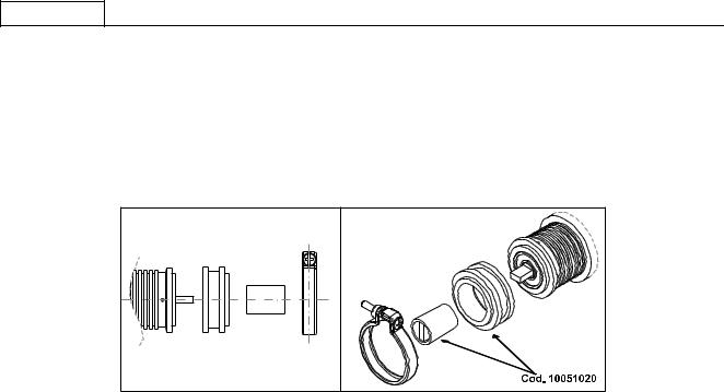
The impurities filter (code 10355150) is normally mounted on the hose connecting the purifier to the pump (fig. A) to prevent impurities in the water from damaging downstream components such as the pumping head, flow pumps, solenoid valves, etc.
The capsule filter (code 10355162) which blocks the impurities present in the water must be replaced about every three months.
The three month period is indicative only as the actual length of time is correlated to water consumption and the impurities present in the mains water supply.
To replace the pod filter: unscrew the impurities filter (code 10355150) and replace the pod filter. Before inserting the new pod filter, make sure the inside of the body (10355152 and 10355154) is completely clean. Any foreign matter must be removed to ensure correct filtration.
The impurities filter must be mounted according to the flow direction indicated by the arrow (fig. A) on the body.
IMPURITIES FILTER
Part.1 = 10355150 |
10355156 |
10355162 |
10355154 |
10355152 |
A |
1 |
Fig. A |
USE
PRELIMINARY CHECK
Before using the appliance, check that:
-the plug is inserted properly into the mains power outlet;
-the water filling hose is correctly connected to the mains water outlet, check for leaks and that the water tap is open;
-the drain pipe is positioned in accordance with the preceding instructions.
With the steam tap (B) open, place the ON/OFF switch (D) in the 1 position and wait for the water in the boiler to reach the maximum level established by the electronic control unit. If the boiler does not fill within the set timeout (90 secs.), the pump stops and the keypad LEDs flash. In this case put the on/off switch (D) to position 0 and then to position 1 to finish filling the boiler.
Now put the on/off switch (D) to position 2 so that the heating elements are powered and therefore start to heat the water.
Wait for steam to come out the steam nozzle (B), then close the tap and, using the Boiler pressure gauge, check that the pressure has reached and maintains a value of 0.8:1 bar. Pressure switch
If this is not the case, use a screwdriver to regulate the adjustment screw in the pres-sure switch (+ to increase, - to decrease, see figure below).
HOT WATER DELIVERY
Make sure the boiler pressure gauge shows a pressure of 0.5:1 bars.
Press the button (M6) to deliver hot water, then press again to stop delivery.
Take great care to avoid burns.
STEAM DELIVERY
All models have two steam nozzles on the sides of the work surface, with the exception of the one group machine which has just one. These steam
19

ENGLISH
nozzles are retractable and can be oriented by means of a ball joint. To deliver steam, turn the knobs (B) anticlockwise. Take great care to avoid burns.
COFFEE DELIVERY ZOE COMPACT SAP MODEL
Insert the filter holder (E) into the group head (F) turning the filter holder counter-clockwise. Press the button (M5) and wait for the required quantity of coffee to be dispensed, press it again.
COFFEE DELIVERY ZOE COMPACT SED MODEL
Insert the filter holder (E) in its seat (F) by turning it anticlockwise. Select the type of delivery required on the keypad (M): M1=One short/standard coffee.
M2=One standard/long coffee. M1=Two short/standard coffees. M4=Two standard/long coffees.
M5=Electronic settings button or continuous manual delivery.
Before use, the operator must always check the indicator (L) to make sure that the level of water in the boiler is above the minimum level.
DISPENSER PROGRAMMING
a)To access this phase keep the button M5 on the first pushbutton panel on the left pressed for over 5 seconds. The indicator lights of the buttons
M5 start to blink continuously. Select the caption corresponding to the amount required and press to dispense. The indicator light of button
M5 and that of the selected caption remain lit. When the required amount has been dispensed, press the selected dispensing button again so that the control unit stores the data. Repeat the above procedure for all 4 dispensing buttons on the pushbutton panel. A dispensed quantity may also be set for the hot water button (M6) by repeating the above procedure. Upon completion of the procedure, the remaining groups will automatically use the stored quantity. The other groups may, however, be programmed independently by repeating the same procedure as above after having programmed the first group on the left.
b)There are 2 safety systems inside the control unit designed to protect the electronic system and the various parts of the appliance. If, upon pressing a dispensing button, the corresponding indicator light starts blinking, this indicates a malfunction in the electronic system or lack of water. For safety reasons, the dispensing of water stops after 4 minutes and in any case after 4 litres of water.
c)The ZOE COMPACT SED electronics also offers the possibility of reproducing the pre-brewing effect by wetting the coffee for 0.6 seconds and then stopping the subsequent brewing from starting for 1.2 seconds. This option is only applicable for single shots of coffee.
TO ENABLE PRE-BREWING
With the appliance switched off, put the on/off switch (D) to position 1 and at the same time keep the button (M1) on the left-hand group pressed until the indicator light corresponding to the button (M5) remains lit; then release the button (M1). Now put the on/off switch (D) to position 0 and
then to position 2 in order to store the operation.
TO DISABLE PRE-BREWING
With the appliance switched off, put the on/off switch (D) to position 1 and at the same time keep the button (M2) on the left-hand group pressed until the indicator light corresponding to the button (M5) remains lit; then release the button (M2). Now switch the appliance off and then on again
using the on/off switch (D) in order to store the operation.
CLEANING
Spout assembly filter: after having dispensed the last cup of coffee, the filter and filter holder must be washed with water. If they are damaged, worn or clogged, they should be replaced.
Drip tray and grid: the drip tray and grid should be removed frequently and coffee residues cleaned away.
Water softener: the softener should be periodically regenerated according to the manufacturer’s directions given in the instruction booklet.
External housing: the external housing and the steel parts should be cleaned with sponges and soft cloths to avoid scratching. Only use detergents that do not contain abrasive powders or solvents and do not use steel wool.
WARNINGS: when using the appliance it is recommended that the various instruments be kept under control, checking that they are in the previously indicated normal working conditions.
When the appliance has been left unused for a number of days, or every 2/3 months during normal use, to clean the internal circuits more efficiently, it is good practice to fill the boiler a number of times and deliver simple water and coffee to be thrown away.
APPLIANCE FAILURE
The user must check that this is not due to:
-power failure or blackout.
-lack of mains water supply or no water inside the boiler.
For any other causes, contact a qualified SANREMO After-Sales Service Centre.
BEFORE CARRYING OUT ANY WORK INSIDE THE APPLIANCE OR REMOVING ANY PART OF THE HOUSING, ALWAYS DISCONNECT FROM THE ELECTRICITY SUPPLY.
WARRANTY
Every purchased appliance (keep the receipt, invoice and delivery note) is covered by a statutory guarantee. This warranty envisages the replacement
20
ENGLISH
free of charge of parts that are shown to the service centre or manufacturer’s satisfaction to be defective due to faulty materials or workmanship and providing that the appliance has not been misused or tampered with by unauthorised persons or persons using incorrect components or techniques.
Any defective part shall be returned to the manufacturer.
NOTE: never activate the pump without water. Excessive heat will damage the pump and no warranty replacement is granted in that case.
WARNINGS
The appliance must not be cleaned using a water jet. Do not put the appliance in water.
The appliance must not be positioned near to any source of heat. The appliance is unsuitable for outdoor installation.
Children must be supervised to make sure they do not play with the appliance.
The appliance must be installed in places where its use and maintenance is limited to qualified persons only.
Access to the service area is limited to persons with knowledge and practical experience of the appliance, particularly as regards safety and hygiene aspects.
To ensure safe use the appliance must be in a level position.
If the power cable is damaged, have it replaced by a SANREMO After-Sales Service Centre, since a special tool is required for this purpose. The appliance must be used in rooms with a temperature between 5°C and 35°C.
IN THE EVENT OF FAILURE OR MALFUNCTION, REQUEST SERVICE ONLY FROM QUALIFIED PERSONNEL AT THE AFTER-SALES SERVICE CENTRE.
The data and features indicated in this booklet are not binding on the manufacturer, which reserves the right to make changes to its models at any time.
The manufacturer shall not be under any liability for injury to persons or damage to property arising from failure to comply with the instructions given in this booklet.
INFORMATION FOR USERS
In accordance with article 13 of legislative decree no. 151 “Implementation of directives 2002/95/EC, 2002/96/EC and 2003/108/EC on restriction of the use of certain hazardous substances in electrical and electronic equipment and the disposal of waste”.
The appliance or packaging is marked with the symbol of a bin with a cross to indicate that at the end of its working life it must be disposed of separately from other waste.
Separate collection of this appliance at the end of its working life is organised and managed by the manufacturer.
The user wanting to dispose of this appliance should therefore contact the manufacturer and follow the separate waste collection system to dispose of the appliance at the end of its working life.
Appropriate separate collection and the subsequent recycling, treatment and ecological disposal of the disused appliance help avoid possible negative effects on the environment and health and encourage the re-use and/or recycling of the constituent materials.
The unlawful disposal of the product by the user is punishable by the administrative sanctions provided for by the legislation in force at the time.
21
ENGLISH
If the cables are damaged, contact an au-thorised service centre as replacement re-quires a special tool.
SOFTENER
/
MAINS WATER SUPPLY
LEGEND
D – MAIN SWITCH
0 – OFF
1 – PUMP AND AUTOMATISMS ON
2 – PUMP, AUTOMATISMS AND ELECTRIC HEATING ON Q – CUP WARMER ON/OFF SWITCH
LIT - ON
NOT LIT = OFF
R – CUP WARMER RESISTOR
S – 3-WAY BLOCK FEMALE
T – 3-WAY BLOCK MALE
U – WATER FILL DRIVE HOSE
V – EXTERNAL PUMP
Connect the external pump stably on its feet.
The pump must be kept away from sources of heat or water.
22
ENGLISH
Warning – correct use of rotary pumps
1-Proper Alignment of Pump and Motor
On occasion the noise of a motor-pump assembly is caused by a poor alignment.
When the coupling between motor and pump is rigid, the pump rotor and the motor rotor may be out of axis. If this condition is maintained over time the most likely damage is seizure of the pump.
An efficient solution of this problem is the use of an elastic coupling between pump and motor. Fluid-o Tech supplies an optional kit code N. 10051020.
2-Quality of Water.
Tight mechanical tolerances of components and materials used for rotary vane pumps require a very clean water, free from suspended particles. Sand, deposits on connecting pipes or the resins of the sweetener, when flowing through the pump, may scratch graphite parts causing problems of insufficient pressure and flow rate.
If a closed loop hydraulic circuit is not available to guarantee a clean water and no sources of contamination Fluid-o-Tech recommend to install a 5-10 micron filter between the sweetener and the pump.
Recommended filter: food approved polipropilene wire cartridge.
Keep the filter clean.: an upstream dirty filter will create cavitation and the pump will break shortly (see section 4).
3-Dry operation
Rotary vane pumps may operate in dry condition only for a very short timefew seconds!
Without a proper water cooling the temperature of the mechanical seal will increase very quickly with resulting breakage. The most likely impact is a remarkable leak visible from the four drain holes close to the motor clamp . For potential lack of feed from city water line Fluid-o-Tech recommend the installation of a minimum pressure safety switch upstream from the pump.
In case of feed from a tank install on the tank a minimum level switch.
4-Cavitation
Cavitation shows when feed flow rate does not match the pump design requirement: most frequent causes are dirty filters, small diameter pipes, more users on the same line.
Opening of the safety valve (generally installed upstream from pump and filter) must happen
before the pump start up. This will avoid cavitation. For the same reason closing of the safety valve must be delayed after the pump shut down.
The most noticeable effect is an increase of noise. If cavitation continues the impact is the same as of dry operation.
5-Back Feed of Hot Water
If a non return valve between the pump and the hot water vessel is defective the pump may come in contact with hot water(90-
100°C). Dimensional variations of components will cause seizure of the pump.
6) Wrong connections
Pumps connectors are 3/8”NPT(conical) or 3/8” GAS(cylindrical).
Connectors with thread different from the recommended type are occasionally used. Sealing is made with a glue or with teflon tape. If the connector is forced it is possible to create beards; if excess sealing glue is used the extra quantity of glue may enter into the pump body.
In both cases it is likely to create a damage.
7) Pressure strokes
To avoid pressure strokes opening of solenoid valves installed downstream must happen before the start of the pump. For the same reason closing of the valve must be delayed after stopping of the pump.
A pressure stroke may break graphite parts and damage mechanical seal causing blockage of the pump and leaks.
8) Handling
A crash on the floor may create deformations that will jeopardize the tight mechanical tolerances of the pump components. For the
23
 Loading...