

Page 1
REPAIR PARTS LIST and DRAWING
A WARREN RUPP PUMP BRAND
ITEM TOTAL
NO. PART NUMBER DESCRIPTION RQD.
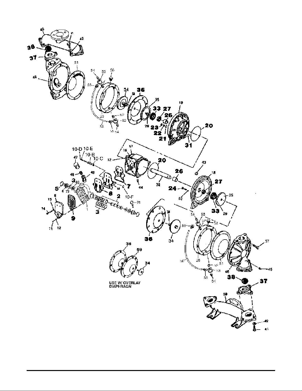
1 095-051-551 Body, Spool Valve 1
2 031-083-000 Sleeve & Spool Set w/Pins 1
3 560-058-360 O-Ring 8
5 675-043-115 Ring, Retaining 2
4 165-078-147 Cap, End 2
6 165-042-157 Cap, Valve Body 1
7 360-056-360 Gasket 1
8 360-057-360 Gasket 1
9 360-058-360 Gasket 1
10 095-074-000 Assembly., Pilot Valve* 1
10-A 095-071-551 Valve Body 1
10-B 755-025-000 Sleeve (without o-ring) 1
10-C 560-033-360 O-Ring (Sleeve) 4
10-D 775-014-000 Spool (without o-ring) 1
10-E 560-023-360 O-Ring (Spool) 4
10-F 675-037-080 Retaining Ring 1
11 170-063-330 Capscrew, Hex Head 1
12 901-035-330 Washer, Flat 7
13 542-001-330 Nut, Square 1
14 170-033-330 Capscrew, Hex Head 4
15 901-005-330 Washer, Flat 4
16 170-043-330 Capscrew, Hex Head 6
170-006-330 Capscrew, Hex Head 6
17 114-007-157 Bracket, lntermediate 1
18 196-042-157 Chamber, Inner 1
19 196-043-157 Chamber, Inner 1
20 560-040-360 O-Ring 2
21 560-001-360 O-Ring 2
22 135-013-162 Bushlng 2
23 675-042-115 Ring, Retainer 2
24 620-007-114 Plunger, Actuator 2
25 196-135-156 Chamber, Driver 2
196-139-156 Chamber, Driver (w/ PTFE overlay) 2
26 070-012-170 Bearing, Sleeve 2
27 720-010-375 Seal, U-Cup 2
29 901-012-180 Washer, Sealing 2
30 807-048-330 Stud 2
31 675-040-360 Ring, Sealing 2
32 685-039-120 Rod, Diaphragm 1
33 132-019-360 Bumper 2
34 612-108-157 Plate, Outer Diaphragm 2
35 612-022-330 Plate, Inner Diaphragm 2
* Available in Kit Form. Order P/N 031-060-000 which also
includes Items 7, 8, 9, 24, & 50.
Model MP05D
Design Level 1
Repair Parts shown in bold face (darker)
type are more likely to need replacement
after extended periods of normal use.
They are readily available from most
MARATHON distributors. The pump
owner may prefer to maintain a limited
inventory of these parts in his own stock
to reduce repair downtime to a minimum.
IMPORTANT: When ordering repair parts
always furnish pump model number, serial
number and type number.
MATERIAL CODES
The Last 3 Digits of Part Number
000…Assembly, sub-assembly;
and some purchased Items
010…Cast Iron
012…Powered Metal
015…Ductile Iron
020…Ferritic Malleable Iron
025…Music Wire
080…CarbonSteel AISI B-1112
100…Alloy 20
110…Alloy Type 316 Stainless Steel
111…Alloy Type 316 Stainless Steel (Electro
Polished)
112…Alloy “C”
113…Alloy Type 316 Stainless Steel (Hand Polished)
114…303 Stainless Steel
115…302/304 Stainless Steel
117…440-C Stainless Steel (Martensitic)
120…416 Stainless Steel (Wrought Martensitic)
123…410 Stainless Steel (Wrought Martensitic)
148…Hardcoat Anodized Aluminum
149…2024-T4 Aluminum
150…6061-T6 Aluminum
151…6063-T6 Aluminum
152…2024-T4 Aluminum (2023-T351)
154…Almag 35 Aluminum
155 or 156…356-T6 Aluminum
157…Die Cast Aluminum Alloy #380
158…Aluminum Alloy SR-319
159…Anodized Aluminum
162…Brass, Yellow, Screw Machine Stock
165…Cast Bronze, 85-5-5-5
166…Bronze SAE 660
170…Bronze, Bearing Type, Oil Impregnated
180…Copper Alloy
310…Kynar Coated
330…Zinc Plated Steel
331…Chrome Plated Steel
332…Electroless Nickel Plated
335…Galvanized Steel
336…Zinc Plated Yellow Brass
337…Silver Plated Steel
340…Nickel Plated
342…Filled Nylon
354…Injection Molded #203-40 Santoprene
- Duro 40D ± 5; Color: RED
355…Thermoplastic Elastomer
356…Hytrel
357…Rupplon (Urethane Rubber) Color
coded:PURPLE
358…Rupplon (Urethane Rubber)
Color coded:PURPLE
(Some Applications, Compression Mold)
359…Urethane Rubber
360…Buna-N Rubber Color coded: RED
361…Buna-N
363…Viton (Fluorel) Color coded: YELLOW
364…E.P.D.M. Rubber Color coded: BLUE
365…Neoprene Rubber Color coded: GREEN
370…Butyl Rubber Color coded: BROWN
371…Philthane (Tuftane)
List continued next page
WARREN RUPP, INC. A Unit of IDEX Corporation • P.O. Box 1568 • Mansfield, Ohio 44901-1568 USA • (419) 524-8388 Fax (419) 522-7867
520-168-000 3/03 Model MP05D Design Level 1 Page 1
Page 2

ITEM TOTAL
NO. PART NUMBER DESCRIPTION RQD.
36 286-008-365 Diaphragm 2
286-008-363 Diaphragm 2
286-008-360 Diaphragm 2
286-008-364 Diaphragm 2
286-008-354 Diaphragm 2
37 722-045-365 Seat, Valve 4
722-045-360 Seat, Valve 4
722-045-600 Seat, Valve 4
38 050-019-365 Ball, Check Valve 4
050-019-360 Ball, Check Valve 4
050-024-600 Ball, Check Valve 4
39 518-122-156 Manifold, Suction 1
40 518-121-156 Manifold, Discharge 1
41 170-029-330 Capscrew. Hex Head 12
42 901-039-330 Washer, Flat 12
43 545-004-330 Nut, Hex 16
44 618-003-330 Pipe, Plug 1
45 618-003-330 Pipe Plug 2
46 196-057-156 Chamber, Outer 2
47 530-018-000 Muffler, Exhaust 1
48 312-044-555 45° Elbow 1
49 538-025-555 Nipple, Close 1
50 132-022-360 Bumper 2
51 286-066-365 Diaphragm 2
286-066-360 Diaphragm 2
286-066-363 Diaphragm 2
286-066-364 Diaphragm 2
286-066-354 Diaphragm 2
286-040-604 Diaphragm 2
52 538-083-115 Nipple, Pipe 4
53 835-005-115 Tee, Pipe 4
54 618-003-110 Plug, Pipe 4
55 866-060-115 Fitting, Male 4
56 860-054-606 Tube, Sight 2
57 170-099-330 Capscrew, Hex Head 16
58 618-025-110 Boss Plug and O-Ring 2
59 286-015-604 Diaphragm, PTFE (Overlay) 2
69 132-028-552 Bumper, Spool 2
71 210-008-330 C lip , Safe ty 1
72 560-029-360 O-Ring 2
Repair Parts shown in bold face (darker)
type are more likely to need replacement
after extended periods of normal use.
They are readily available from most
MARATHON distributors. The pump
owner may prefer to maintain a limited
inventory of these parts in his own stock
to reduce repair downtime to a minimum.
IMPORTANT: When ordering repair parts
always furnish pump model number, serial
number and type number.
MATERIAL CODES
The Last 3 Digits of Part Number
Continued from previous page
375…Fluorinated Nitrile
378…High density Polypropylene
405…Cellulose Fibre
408…Cork and Neoprene
425…Compressed Fibre
426…Blue Gard
440…Vegetable Fibre
465…Fibre
500…Delrin 500
501…Delrin 570
505…Acrylic Resin Plastic
520…Injection Molded PVDF Natural Color
540…Nylon
541…Nylon
542…Nylon
544…Nylon Injection Molded
550…Polyethylene
551…Polypropylene
552…Unfilled Polypropylene
553…Unfilled Polypropylene
555…Polyvinyl Chloride
570…Rulon II
580…Ryton
590…Valox
591…Nylatron G-S
592…Nylatron NSB
600…PTFE (virgin material) Tetrafluoroethylene (TFE)
601…PTFE (Bronze and moly filled)
602…Filled PTFE
603…Blue Gylon
604…PTFE
606…PTFE
610…PTFE Encapsulated Silicon
611…PTFE Encapsulated Viton
Delrin, PTFE, Viton and Hytrel are registered
tradenames of E.I. DuPont.
Gylon is a registered tradename of Garlock. Inc.
Nylatron is a registered tradename of Polymer Corp.
Rulon II is a registered tradename of Dixion Industries
Corporation.
Hastelloy-C is a registered tradename of Cabot Corp.
Ryton is a registered tradename of Phillips Chemical
Company.
Valox is a registered tradename of General Electric
Company.
Not Shown:
031-111-000 Valve Body Assy. 1
(Consists of items 1, 2, 3, 4, 5,
69, 71 & 72)
Model MP05D Design Level 1 Page 2 520-168-000 3/03
Page 3
Note: For models using PTFE
pumping diaphragms, (Item 51) the
natural bulge goes toward the
center of the pump.
©2003 Warren Rupp, Inc. All rights reserved.
Printed in U.S.A.
520-168-000 3/03 Model MP05D Design Level 1 Page 3
Page 4
REPAIR PARTS LIST and DRAWING
A WARREN RUPP PUMP BRAND
ITEM TOTAL
NO. PART NUMBER DESCRIPTION RQD.
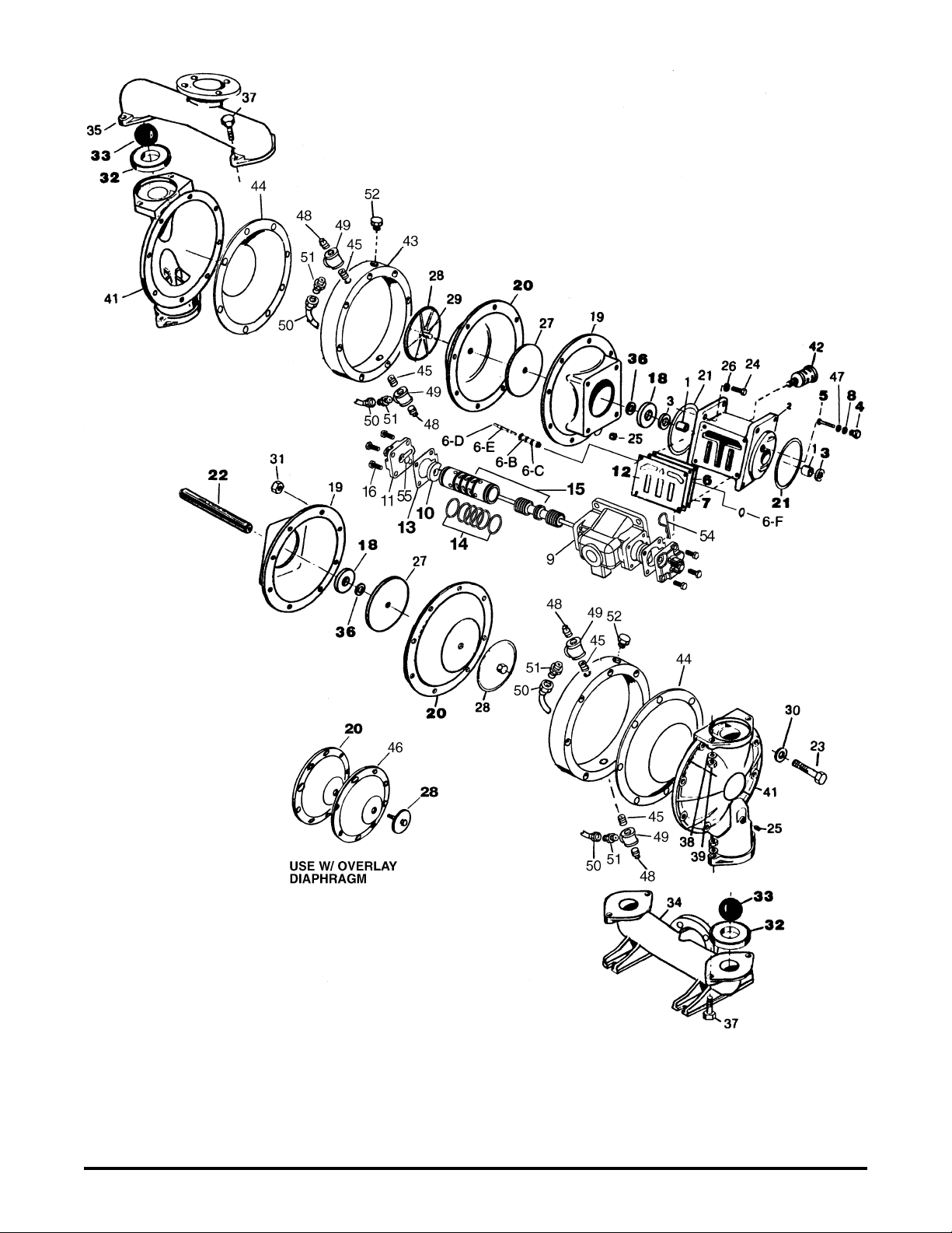
1 070-006-170 Bearing, Sleeve 2
2 114-002-156 Bracket, Intermediate 1
3 720-004-360 Seal, U-Cup 2
4 135-008-000 Bushing, Threaded, with o-ring 2
5 620-004-114 Plunger, Actuator 2
6 095-073-000 Assembly, Pilot Valve* 1
6-A 095-070-551 Valve Body 1
6-B 755-025-000 Sleeve (without o-ring) 1
6-C 560-033-360 O-Ring (Sleeve) 4
6-D 775-026-000 Spool (without o-ring) 1
6-E 560-023-360 O-Ring (Spool) 2
6-F 675-037-080 Retaining Ring 1
7 360-041-425 Gasket, Valve Body 1
8 560-001-360 O-Ring 2
9 095-043-156 Body, Valve 1
10 132-014-358 Bumper, Valve Spool 2
11 165-066-010 Cap, End 2
12 360-048-425 Gasket, Valve Body 1
13 360-010-425 Gasket, End Cap 2
14 560-020-360 O-Ring 6
15 031-066-000 Sleeve & Spool Set 1
16 170-032-330 Capscrew, Hex Head 8
17 170-045-330 Capscrew, Hex Head 4
18 132-002-360 Bumper, Diaphragm 2
19 196-001-157 Chamber, Inner 2
20 286-007-365 Diaphragm 2
286-007-363 Diaphragm 2
286-007-360 Diaphragm 2
286-007-366 Diaphragm 2
286-007-364 Diaphragm 2
286-007-356 Diaphragm 2
21 560-022-360 O-Ring 2
22 685-007-120 Rod, Diaphragm 1
23 170-100-330 Capscrew, Hex Head 16
24 170-024-330 Capscrew, Hex Head 8
25 618-003-330 Plug, Pipe 4
26 900-006-330 Washer, Lock 8
27 612-047-330 Plate, Diaphragm 2
28 612-039-157 Plate, Outer 2
29 807-026-330 Stud 2
30 901-022-330 Flat Washer 16
31 545-007-330 Nut, Hex 16
32 722-040-365 Seat, Valve 4
722-040-363 Seat, Valve 4
722-040-360 Seat, Valve 4
722-040-364 Seat, Valve 4
722-040-600 Seat, Valve 4
722-040-110 Seat, Valve 4
Model MP08D
Design Level 1
Repair Parts shown in bold face (darker)
type are more likely to need replacement
after extended periods of normal use.
They are readily available from most
MARATHON distributors. The pump owner
may prefer to maintain a limited inventory
of these parts in his own stock to reduce
repair downtime to a minimum.
IMPORTANT: When ordering repair parts
always furnish pump model number, serial
number and type number.
MATERIAL CODES
The Last 3 Digits of Part Number
000…Assembly, sub-assembly;
and some purchased Items
010…Cast Iron
012…Powered Metal
015…Ductile Iron
020…Ferritic Malleable Iron
025…Music Wire
080…CarbonSteel AISI B-1112
100…Alloy 20
110…Alloy Type 316 Stainless Steel
111…Alloy Type 316 Stainless Steel (Electro
Polished)
112…Alloy “C”
113…Alloy Type 316 Stainless Steel (Hand Polished)
114…303 Stainless Steel
115…302/304 Stainless Steel
117…440-C Stainless Steel (Martensitic)
120…416 Stainless Steel (Wrought Martensitic)
123…410 Stainless Steel (Wrought Martensitic)
148…Hardcoat Anodized Aluminum
149…2024-T4 Aluminum
150…6061-T6 Aluminum
151…6063-T6 Aluminum
152…2024-T4 Aluminum (2023-T351)
154…Almag 35 Aluminum
155 or 156…356-T6 Aluminum
157…Die Cast Aluminum Alloy #380
158…Aluminum Alloy SR-319
159…Anodized Aluminum
162…Brass, Yellow, Screw Machine Stock
165…Cast Bronze, 85-5-5-5
166…Bronze SAE 660
170…Bronze, Bearing Type, Oil Impregnated
180…Copper Alloy
310…Kynar Coated
330…Zinc Plated Steel
331…Chrome Plated Steel
332…Electroless Nickel Plated
335…Galvanized Steel
336…Zinc Plated Yellow Brass
337…Silver Plated Steel
340…Nickel Plated
342…Filled Nylon
354…Injection Molded #203-40 Santoprene
- Duro 40D ± 5; Color: RED
355…Thermoplastic Elastomer
356…Hytrel
357…Rupplon (Urethane Rubber) Color
coded:PURPLE
358…Rupplon (Urethane Rubber)
Color coded:PURPLE
(Some Applications, Compression Mold)
359…Urethane Rubber
360…Buna-N Rubber Color coded: RED
361…Buna-N
363…Viton (Fluorel) Color coded: YELLOW
364…E.P.D.M. Rubber Color coded: BLUE
365…Neoprene Rubber Color coded: GREEN
370…Butyl Rubber Color coded: BROWN
371…Philthane (Tuftane)
List continued next page
WARREN RUPP, INC. A Unit of IDEX Corporation • P.O. Box 1568 • Mansfield, Ohio 44901-1568 USA • (419) 524-8388 Fax (419) 522-7867
520-169-000 3/03 Model MP08D Design Level 1 Page 1
Page 5

ITEM TOTAL
NO. PART NUMBER DESCRIPTION RQD.
33 050-017-365 Ball, Check Valve 4
050-017-360 Ball, Check Valve 4
050-017-364 Ball, Check Valve 4
050-018-600 Ball. Check Valve 4
34 518-119-156 Manifold, Suction 1
35 518-120-156 Manifold, Discharge 1
36 902-003-000 Stat-O-Seal 2
37 170-066-330 Capscrew, Hex Head 8
38 900-003-330 Washer, Lock 8
39 545-008-330 Nut, Hex 8
41 196-047-156 Chamber, Outer 2
42 530-008-000 Muffler, Exhaust 1
43 196-083-156 Chamber, Driver 2
196-140-156 Chamber, Driver (with PTFE overlay) 2
44 286-042-365 Diaphragm 2
286-042-363 Diaphragm 2
286-042-360 Diaphragm 2
286-042-364 Diaphragm 2
286-042-366 Diaphragm 2
286-042-356 Diaphragm 2
286-041-604 Diaphragm 2
45 538-083-115 Nipple, Pipe 4
46 286-020-604 Overlay Diaphragm 2
47 132-022-360 Bumper 2
48 618-003-110 Plug, Pipe 4
49 835-005-115 Tee, Pipe 4
50 426-041-000 Hose Assembly 2
51 866-059-115 Fitting, Male 4
52 618-025-110 Boss Plug and O-Ring 2
53 031-089-156 Main Air Valve Assembly 1
(Inc. Items 9,10,11,13,14, 15, 16)
54 210-008-330 Clip, Safety 1
55 560-023-360 O-Ring, End Cap 2
* Item 6 is available in Kit Form. Order P/N 031-055-000 which also
includes items 5, 7, 12 & 47.
Repair Parts shown in bold face (darker)
type are more likely to need replacement
after extended periods of normal use.
They are readily available from most
MARATHON distributors. The pump owner
may prefer to maintain a limited inventory
of these parts in his own stock to reduce
repair downtime to a minimum.
IMPORTANT: When ordering repair parts
always furnish pump model number, serial
number and type number.
MATERIAL CODES
The Last 3 Digits of Part Number
Continued from previous page
375…Fluorinated Nitrile
378…High density Polypropylene
405…Cellulose Fibre
408…Cork and Neoprene
425…Compressed Fibre
426…Blue Gard
440…Vegetable Fibre
465…Fibre
500…Delrin 500
501…Delrin 570
505…Acrylic Resin Plastic
520…Injection Molded PVDF Natural Color
540…Nylon
541…Nylon
542…Nylon
544…Nylon Injection Molded
550…Polyethylene
551…Polypropylene
552…Unfilled Polypropylene
553…Unfilled Polypropylene
555…Polyvinyl Chloride
570…Rulon II
580…Ryton
590…Valox
591…Nylatron G-S
592…Nylatron NSB
600…PTFE (virgin material) Tetrafluoroethylene (TFE)
601…PTFE (Bronze and moly filled)
602…Filled PTFE
603…Blue Gylon
604…PTFE
606…PTFE
610…PTFE Encapsulated Silicon
611…PTFE Encapsulated Viton
Delrin, PTFE, Viton and Hytrel are registered
tradenames of E.I. DuPont.
Gylon is a registered tradename of Garlock. Inc.
Nylatron is a registered tradename of Polymer Corp.
Rulon II is a registered tradename of Dixion Industries
Corporation.
Hastelloy-C is a registered tradename of Cabot Corp.
Ryton is a registered tradename of Phillips Chemical
Company.
Valox is a registered tradename of General Electric
Company.
Model MP08D Design Level 1 Page 2 520-169-000 3/03
Page 6
Note: For models using PTFE
pumping diaphragms, (Item 44) the
natural bulge goes toward the
center of the pump.
©2003 Warren Rupp, Inc. All rights reserved.
Printed in U.S.A.
520-169-000 3/03 Model MP08D Design Level 1 Page 3
Page 7

REPAIR PARTS LIST and DRAWING
A WARREN RUPP PUMP BRAND
ITEM TOTAL
NO. PART NUMBER DESCRIPTION RQD.
1 070-006-170 Bearing, Sleeve 2
2 114-002-156 Bracket, Intermediate 1
3 720-004-360 Seal, U-Cup 2
4 135-008-000 Bushing, Threaded, with O-Ring 2
5 620-004-114 Plunger, Actuator 2
6 095-073-000 Pilot Valve Body Assembly* 1
6-A 095-070-551 Pilot Valve Body 1
6-B 755-025-000 Sleeve (with O-Ring) 1
6-C 560-033-360 O-Ring (Sleeve) 4
6-D 775-026-000 Spool (with O-Ring) 1
6-E 560-023-360 O-Ring (Spool) 2
6-F 675-037-080 Retaining Ring 1
7 360-041-425 Gasket, Valve Body 1
8 560-001-360 O-Ring 2
9 095-043-156 Body, Valve 1
10 132-014-358 Bumper, Valve Spool 2
11 165-066-010 Cap, End 2
12 360-048-425 Gasket, Valve Body 1
13 360-010-425 Gasket, End Cap 2
14 560-020-360 O-Ring 6
15 031-069-000 Sleeve & Spool Set 1
16 170-032-330 Capscrew Hex Head 8
17 170-045-330 Capscrew, Hex Head 4
18 132-002-360 Bumper, Diaphragm 2
19 196-001-157 Chamber, Inner 2
20 286-007-365 Diaphragm 2
286-007-363 Diaphragm 2
286-007-360 Diaphragm 2
286-007-354 Diaphragm 2
286-007-356 Diaphragm 2
286-007-364 Diaphragm 2
21 560-022-360 O-Ring 2
22 685-007-120 Rod, Diaphragm 1
23 170-024-330 Capscrew, Hex Head 8
24 618-003-330 Plug, Pipe 4
25 900-006 330 Washer, Lock 8
26 612-047-330 Plate, Diaphragm 2
27 902-003-000 Stat-O-Seal 2
28 530-008-000 Muffler, Exhaust 1
31 031-090-156 Main Air Valve Asembly
(Includes Items 9, 10, 11, 13, 14,
15 & 16) 1
33 612-039-157 Plate, Outer Diaphragm Assembly 2
(Includes Item 34)
34 807-026-330 Stud 2
*Item 6 is available in kit form. Order P/N 031-055-000 which also
includes items 5, 7, 12 & 48.
Model MP12D
Design Level 1
Repair Parts shown in bold face (darker)
type are more likely to need replacement
after extended periods of normal use.
They are readily available from most
MARATHON distributors. The pump owner
may prefer to maintain a limited inventory
of these parts in his own stock to reduce
repair downtime to a minimum.
IMPORTANT: When ordering repair parts
always furnish pump model number, serial
number and type number.
MATERIAL CODES
The Last 3 Digits of Part Number
000…Assembly, sub-assembly;
and some purchased Items
010…Cast Iron
012…Powered Metal
015…Ductile Iron
020…Ferritic Malleable Iron
025…Music Wire
080…CarbonSteel AISI B-1112
100…Alloy 20
110…Alloy Type 316 Stainless Steel
111…Alloy Type 316 Stainless Steel (Electro
Polished)
112…Alloy “C”
113…Alloy Type 316 Stainless Steel (Hand Polished)
114…303 Stainless Steel
115…302/304 Stainless Steel
117…440-C Stainless Steel (Martensitic)
120…416 Stainless Steel (Wrought Martensitic)
123…410 Stainless Steel (Wrought Martensitic)
148…Hardcoat Anodized Aluminum
149…2024-T4 Aluminum
150…6061-T6 Aluminum
151…6063-T6 Aluminum
152…2024-T4 Aluminum (2023-T351)
154…Almag 35 Aluminum
155 or 156…356-T6 Aluminum
157…Die Cast Aluminum Alloy #380
158…Aluminum Alloy SR-319
159…Anodized Aluminum
162…Brass, Yellow, Screw Machine Stock
165…Cast Bronze, 85-5-5-5
166…Bronze SAE 660
170…Bronze, Bearing Type, Oil Impregnated
180…Copper Alloy
310…Kynar Coated
330…Zinc Plated Steel
331…Chrome Plated Steel
332…Electroless Nickel Plated
335…Galvanized Steel
336…Zinc Plated Yellow Brass
337…Silver Plated Steel
340…Nickel Plated
342…Filled Nylon
354…Injection Molded #203-40 Santoprene
- Duro 40D ± 5; Color: RED
355…Thermoplastic Elastomer
356…Hytrel
357…Rupplon (Urethane Rubber) Color
coded:PURPLE
358…Rupplon (Urethane Rubber)
Color coded:PURPLE
(Some Applications, Compression Mold)
359…Urethane Rubber
360…Buna-N Rubber Color coded: RED
361…Buna-N
363…Viton (Fluorel) Color coded: YELLOW
364…E.P.D.M. Rubber Color coded: BLUE
365…Neoprene Rubber Color coded: GREEN
370…Butyl Rubber Color coded: BROWN
371…Philthane (Tuftane)
List continued next page
WARREN RUPP, INC. A Unit of IDEX Corporation • P.O. Box 1568 • Mansfield, Ohio 44901-1568 USA • (419) 524-8388 Fax (419) 522-7867
520-170-000 3/03 Model MP12D Design Level 1 Page 1
Page 8

ITEM TOTAL
NO. PART NUMBER DESCRIPTION RQD.
35 722-041-365 Seat, Valve 4
722-041-360 Seat, Valve 4
722-041-363 Seat, Valve 4
722-041-364 Seat, Valve 4
722-041-600 Seat, Valve 4
36 050-014-365 Ball, Check Valve 4
050-014-364 Ball, Check Valve 4
050-014-360 Ball, Check Valve 4
050-015-600 Ball, Check Valve 4
37 518-123-156 Manifold, Suction 1
38 518-124-156 Manifold, Discharge 1
39 900-003-330 Washer, Lock 16
40 170-055-330 Capscrew, Hex Head. 1 2
41 170-034-330 Capscrew, Hex Head. 4
42 170-086-330 Capscrew, Hex Head. (tapped holes) 8
43 196-062-156 Chamber, Outer 2
44 326-002-080 Mounting, Food 2
45 286-020-604 Overlay Diaphragm 2
46 170-100-330 Capscrew, Hex Head. 8
47 545-007-330 Hex Nut 8
48 132-022-360 Bumper 2
49 196-083-156 Chamber, Driver 2
196-140-156 Chamber, Driver (with PTFE overlay) 2
50 286-042-365 Diaphragm 2
286-042-360 Diaphragm 2
286-042-363 Diaphragm 2
286-042-364 Diaphragm 2
286-042-366 Diaphragm 2
286-042-354 Diaphragm 2
286-042-356 Diaphragm 2
286-041-604 Diaphragm, Overlay 2
51 538-083-115 Nipple, Pipe 4
52 835-005-115 Tee, Pipe 4
53 618-003-110 Plug, Pipe 4
54 866-059-115 Fitting, Male 4
55 426-041-000 Hose Assembly 2
56 618-025-115 Boss Plug and O-Ring* 2
*O-ring for Boss Plug is 560-070-611.
If ordering Boss Plug, o-ring is included.
57 210-008-330 Clip, Safety 1
58 560-023-360 O-Ring, End Cap 2
Repair Parts shown in bold face (darker)
type are more likely to need replacement
after extended periods of normal use.
They are readily available from most
MARATHON distributors. The pump owner
may prefer to maintain a limited inventory
of these parts in his own stock to reduce
repair downtime to a minimum.
IMPORTANT: When ordering repair parts
always furnish pump model number, serial
number and type number.
MATERIAL CODES
The Last 3 Digits of Part Number
Continued from previous page
375…Fluorinated Nitrile
378…High density Polypropylene
405…Cellulose Fibre
408…Cork and Neoprene
425…Compressed Fibre
426…Blue Gard
440…Vegetable Fibre
465…Fibre
500…Delrin 500
501…Delrin 570
505…Acrylic Resin Plastic
520…Injection Molded PVDF Natural Color
540…Nylon
541…Nylon
542…Nylon
544…Nylon Injection Molded
550…Polyethylene
551…Polypropylene
552…Unfilled Polypropylene
553…Unfilled Polypropylene
555…Polyvinyl Chloride
570…Rulon II
580…Ryton
590…Valox
591…Nylatron G-S
592…Nylatron NSB
600…PTFE (virgin material) Tetrafluoroethylene (TFE)
601…PTFE (Bronze and moly filled)
602…Filled PTFE
603…Blue Gylon
604…PTFE
606…PTFE
610…PTFE Encapsulated Silicon
611…PTFE Encapsulated Viton
Delrin, PTFE, Viton and Hytrel are registered
tradenames of E.I. DuPont.
Gylon is a registered tradename of Garlock. Inc.
Nylatron is a registered tradename of Polymer Corp.
Rulon II is a registered tradename of Dixion Industries
Corporation.
Hastelloy-C is a registered tradename of Cabot Corp.
Ryton is a registered tradename of Phillips Chemical
Company.
Valox is a registered tradename of General Electric
Company.
Model MP12D Design Level 1 Page 2 520-170-000 3/03
Page 9

Note: For models using PTFE
pumping diaphragms, (Item 50)
the natural bulge goes toward the
center of the pump.
©2003 Warren Rupp, Inc. All rights reserved.
Printed in U.S.A.
520-170-000 3/03 Model MP12D Design Level 1 Page 3
Page 10

REPAIR PARTS LIST and DRAWING
A WARREN RUPP PUMP BRAND
ITEM TOTAL
NO. PART NUMBER DESCRIPTION RQD.
1 070-006-170 Bearing, Sleeve 2
2 114-002-156 Bracket, Intermediate 1
114-002-010 Bracket, Intermediate 2
3 720-004-360 Seal, U-Cup 2
4 135-008-000 Bushing, Threaded, with O-Ring 2
5 620-004-114 Plunger, Actuator 2
6 095-073-000 Pilot Valve Body Assembly* 1
6-A 095-070-551 Pilot Valve Body 1
6-B 755-025-000 Sleeve (with O-Ring) 1
6-C 560-033-360 O-Ring (Sleeve) 4
6-D 775-026-000 Spool (with O-Ring) 1
6-E 560-023-360 O-Ring (Spool) 2
6-F 675-037-080 Retai nin g Ring 1
7 360-041-425 Gasket, Valve Body 1
8 560-001-360 O-Ring 2
9 095-043-156 Body, Valve (AL) 1
095-043-010 Body, Valve (CI) 1
10 132-014-358 Bumper, Valve Spool 2
11 165-066-010 Cap, End 2
12 360-048-425 Gasket, Valve Body 2
13 360-010-425 Gasket, End Cap 2
14 560-020-360 O-Ring 6
15 031-069-000 Sleeve & Spool Set 1
16 170-032-330 Capscrew Hex Head 8
17 170-069-330 Capscrew, Hex Head 4
18 132-002-360 Bumper, Diaphragm 2
19 196-100-010 Chamber Inner 2
20 132-022-360 Bumper 2
21 560-022-360 O-Ring 2
22 685-041-120 Rod, Diaphragm 1
24 170-024-330 Capscrew Hex Head 8
25 530-008-000 Muffler, Exhaust 1
26 900-006 330 Washer, Lock 8
27 545-008-330 Nut, Hex 16
28 900-003-330 Washer, Lock 32
29 612-124-010 Plate, Inner Diaphragm 2
30 286-098-354 Diaphragm 2
286-098-365 Diaphragm 2
286-098-363 Diaphragm 2
286-098-360 Diaphragm 2
286-098-364 Diaphragm 2
31 722-041-365 Seat, Valve 4
722-041-360 Seat, Valve 4
722-041-363 Seat, Valve 4
722-041-364 Seat, Valve 4
722-041-600 Seat, Valve 4
32 050-014-365 Ball, Check Valve 4
050-014-364 Ball, Check Valve 4
Model MP14D
Design Level 1
Repair Parts shown in bold face (darker)
type are more likely to need replacement
after extended periods of normal use.
They are readily available from most
MARATHON distributors. The pump owner
may prefer to maintain a limited inventory
of these parts in his own stock to reduce
repair downtime to a minimum.
IMPORTANT: When ordering repair parts
always furnish pump model number, serial
number and type number.
MATERIAL CODES
The Last 3 Digits of Part Number
000…Assembly, sub-assembly;
and some purchased Items
010…Cast Iron
012…Powered Metal
015…Ductile Iron
020…Ferritic Malleable Iron
025…Music Wire
080…CarbonSteel AISI B-1112
100…Alloy 20
110…Alloy Type 316 Stainless Steel
111…Alloy Type 316 Stainless Steel (Electro
Polished)
112…Alloy “C”
113…Alloy Type 316 Stainless Steel (Hand Polished)
114…303 Stainless Steel
115…302/304 Stainless Steel
117…440-C Stainless Steel (Martensitic)
120…416 Stainless Steel (Wrought Martensitic)
123…410 Stainless Steel (Wrought Martensitic)
148…Hardcoat Anodized Aluminum
149…2024-T4 Aluminum
150…6061-T6 Aluminum
151…6063-T6 Aluminum
152…2024-T4 Aluminum (2023-T351)
154…Almag 35 Aluminum
155 or 156…356-T6 Aluminum
157…Die Cast Aluminum Alloy #380
158…Aluminum Alloy SR-319
159…Anodized Aluminum
162…Brass, Yellow, Screw Machine Stock
165…Cast Bronze, 85-5-5-5
166…Bronze SAE 660
170…Bronze, Bearing Type, Oil Impregnated
180…Copper Alloy
310…Kynar Coated
330…Zinc Plated Steel
331…Chrome Plated Steel
332…Electroless Nickel Plated
335…Galvanized Steel
336…Zinc Plated Yellow Brass
337…Silver Plated Steel
340…Nickel Plated
342…Filled Nylon
354…Injection Molded #203-40 Santoprene
- Duro 40D ± 5; Color: RED
355…Thermoplastic Elastomer
356…Hytrel
357…Rupplon (Urethane Rubber) Color
coded:PURPLE
358…Rupplon (Urethane Rubber)
Color coded:PURPLE
(Some Applications, Compression Mold)
359…Urethane Rubber
360…Buna-N Rubber Color coded: RED
361…Buna-N
363…Viton (Fluorel) Color coded: YELLOW
364…E.P.D.M. Rubber Color coded: BLUE
365…Neoprene Rubber Color coded: GREEN
370…Butyl Rubber Color coded: BROWN
371…Philthane (Tuftane)
List continued next page
WARREN RUPP, INC. A Unit of IDEX Corporation • P.O. Box 1568 • Mansfield, Ohio 44901-1568 USA • (419) 524-8388 Fax (419) 522-7867 • www.warrenrupp.com
520-171-000 3/03 Model MP14D Design Level 1 Page 1
Page 11

ITEM TOTAL
NO. PART NUMBER DESCRIPTION RQD.
050-014-360 Ball, Check Valve 4
050-015-600 Ball, Check Valve 4
36 518-123-156 Manifold, Suction (AL) 1
518-123-110 Manifold, Suction (SS) 1
37 518-124-156 Manifold, Discharge (AL) 1
518-124-110 Manifold, Discharge (SS) 1
38 170-055-330 Capscrew, Hex Head 1 2
39 326-002-080 Mounting Foot 2
40 286-067-354 Diaphragm 2
286-067-365 Diaphragm 2
286-067-360 Diaphragm 2
286-067-363 Diaphragm 2
286-067-364 Diaphragm 2
286-068-604 Diaphragm 2
41 170-034-330 Capscrew, Hex Head 12
42 807-046-330 Stud 2
43 196-052-156 Chamber, Outer (AL) 2
196-052-110 Chamber, Outer (SS) 2
44 612-090-156 Plate, Outer Diaphragm Assembly 2
52 170-102-330 Capscrew, Hex Head (AL only) 16
170-102-115 Capscrew, Hex Head (SS only) 12
53 196-136-156 Chamber, Driver 2
196-141-156 Chamber, Driver (AL,w/PTFE overlay) 2
196-141-110 Chamber, Driver (SS,w/PTFE overlay) 2
54 426-042-000 Hose Assembly 2
55 866-059-115 Fitting, Male 4
56 618-003-110 Plug, Pipe 4
57 835-005-115 Tee, Pipe 4
58 538-083-115 Nipple, Pipe 4
60 618-025-115 Boss Plug and O-Ring 2
61 210-008-330 C lip , Safe ty 1
62 866-060-110 Connector (SS only) 4
63 860-047-606 Tube, Sight 2
64 807-042-115 Stud 8
65 560-023-360 O-Ring, End Cap 2
66 612-139-010 Plate, Spacer 1
Not Shown:
031-090-156 Main Air Valve Assembly (AL) 1
(Includes Items 9, 10, 11, 13, 14,
15, 16 & 61)
031-090-010 Main Air Valve Assembly (SS) 1
(Includes Items 9, 10, 11, 13, 14,
15, 16 & 61)
Repair Parts shown in bold face (darker)
type are more likely to need replacement
after extended periods of normal use.
They are readily available from most
MARATHON distributors. The pump owner
may prefer to maintain a limited inventory
of these parts in his own stock to reduce
repair downtime to a minimum.
IMPORTANT: When ordering repair parts
always furnish pump model number, serial
number and type number.
MATERIAL CODES
The Last 3 Digits of Part Number
Continued from previous page
375…Fluorinated Nitrile
378…High density Polypropylene
405…Cellulose Fibre
408…Cork and Neoprene
425…Compressed Fibre
426…Blue Gard
440…Vegetable Fibre
465…Fibre
500…Delrin 500
501…Delrin 570
505…Acrylic Resin Plastic
520…Injection Molded PVDF Natural Color
540…Nylon
541…Nylon
542…Nylon
544…Nylon Injection Molded
550…Polyethylene
551…Polypropylene
552…Unfilled Polypropylene
553…Unfilled Polypropylene
555…Polyvinyl Chloride
570…Rulon II
580…Ryton
590…Valox
591…Nylatron G-S
592…Nylatron NSB
600…PTFE (virgin material) Tetrafluoroethylene (TFE)
601…PTFE (Bronze and moly filled)
602…Filled PTFE
603…Blue Gylon
604…PTFE
606…PTFE
610…PTFE Encapsulated Silicon
611…PTFE Encapsulated Viton
Delrin, PTFE, Viton and Hytrel are registered
tradenames of E.I. DuPont.
Gylon is a registered tradename of Garlock. Inc.
Nylatron is a registered tradename of Polymer Corp.
Rulon II is a registered tradename of Dixion Industries
Corporation.
Hastelloy-C is a registered tradename of Cabot Corp.
Ryton is a registered tradename of Phillips Chemical
Company.
Valox is a registered tradename of General Electric
Company.
* Item 6 is available in kit form. Order P/N 031-055-000 which also includes
Items 5, 7, 12, & 20.
Model MP14D Design Level 1 Page 2 520-171-000 3/03
Page 12

Note: For models using
PTFE pumping diaphragms,
(Item 40) the natural bulge
goes toward the center of the
pump.
SS Configuration
©2003 Warren Rupp, Inc. All rights reserved.
Printed in U.S.A.
520-171-000 3/03 Model MP14D Design Level 1 Page 3
Page 13

SERVICE AND OPERATING MANUAL
A WARREN RUPP PUMP BRAND
MP05D MP08D MP12D MP14D
PRINCIPLE OF OPERATION
All SandPlPER pumps, including these spill containment models, operate on the
same basic principle. They are powered by compressed air which alternately
pressurizes the inner sides of the two diaphragm chambers while simultaneously
exhausting the opposite inner chambers causing the diaphragms, which are
connected by a shaft, to move endwise. Since air pressure is applied over the entire
surface of the diaphragm which is forcing liquid to be discharged by its other side,
the diaphragm is operating under a balanced condition during the discharge stroke.
This allows the unit to be operated at discharge heads over 200 feet (61 meters) of
water head.
Alternate pressurizing and exhausting of the diaphragm chamber is performed by
an externally mounted, pilot operated, four way, spool type air distribution valve.
When the spool is at one end of the valve body, inlet air pressure is connected to one
diaphragm chamber and the other diaphragm chamber is connected to the exhaust.
When the spool is removed to the opposite end of the valve body, the porting of
chambers is reversed. The air distribution valve spool is moved from one end
position to the other in the valve body by means of an internal pilot valve which
alternately pressurizes the ends of the air distribution valve spool while simultaneously exhausting the other ends. The pilot valve is positively shifted at each end of
the diaphragm stroke by the diaphragm plate’s coming in contact with the end of the
pilot valve spool and pushing it into position for shifting of the air distribution valve.
The chambers are manifolded together with a suction and discharge check valve for
each chamber to maintain flow in one direction through the pump.
The spill containment pumps differ from standard models in that they utilize four
diaphragms instead of two, the two rod-connected diaphragms being the driver
diaphragms, and the other two (outermost) diaphragms being the actual pumping
diaphragms. Each driver diaphragm (of Neoprene or other elastomer), and the pumping
diaphragm, Teflon or elastomeric, are separated by a spill containment chamber
filled with liquid (typically ethylene glycol, green in color),which transmits the reciprocating motion of the driver diaphragm to the pumping diaphragm. The pumping
diaphragms, in turn, create the alternating suction and discharge action to each outer
diaphragm chamber. In normal operation the pumping diaphragms are the only ones
in contact with the liquid being pumped.
INSTALLATION PROCEDURES
Position the pump as close as possible to the source of the liquid to be pumped.
Avoid long or undersize suction lines and use the minimum number of fittings. High
vacuums reduce flow rate capability and shorten driver diaphragm service life.
For permanent installations involving rigid piping, install short flexible sections of
hose between the pump and piping. This reduces strains and permits easier removal
of the pump for service when required. At time of installation, inspect all external
gasketed fasteners for looseness caused by gasket creep. Tighten loose
fittings securely to prevent leakage.
Design Level 1
IMPORTANT
Read these instructions completely,
before installation and start-up. It is the
responsibility of the purchaser to retain
this manual for reference. Failure to
comply with the recommendations
stated in this manual will damage the
pump, and void factory warranty.
WARNING
Take action to prevent static sparking.
Fire or explosion can result, especially
when handling flammable liquids. The
pump, piping, valves, containers or
other miscellaneous equipment must be
grounded.
HAZARD WARNING
POSSIBLE EXPLOSION HAZARD can
result if 1, 1, 1,-Trichloroethane,
Methylene Chloride or other
Halogenated Hydrocarbon solvents are
used in pressurized fluid systems
having Aluminum or Galvanized wetted
parts. Death, serious bodily injury and/
or property damage could result.
Consult with the factory if you have
questions concerning Halogenated
Hydrocarbon solvents.
CAUTION
The spill containment models should not
be applied in pumping applications
where the driver liquid coming in
contact with the pumped liquid would
create a hazardous condition. This could
happen in case of a pumping diaphragm
failure since this diaphragm normally
separates the two liquids. Also note that
care must be taken to guard against the
operation of this unit if it has been
subjected to freezing temperatures.
Because of the driver liquid used,
possible diaphragm failure may result.
AIR VALVE LUBRICATION
The pump’s pilot valve and main air valve assemblies are
designed to operate WITHOUT lubrication. This is the preferred mode of
operation.
supplies when lubrication of the compressed air supply is required. The pump air
system will operate with properly lubricated compressed air supplies. Proper lubrication
of the compressed air supply would entail the use of an air line lubricator (available
from MARATHON) set to deliver one drop of 10 weight, non-detergent oil for every
20 SCFM of air the pump consumed at its point of operation. Consult the pump’s
published Performance Curve to determine this.
WARREN RUPP, INC. A Unit of IDEX Corporation • P.O. Box 1568 • Mansfield, Ohio 44901-1568 USA • (419) 524-8388 Fax (419) 522-7867 • www.warrenrupp.com
520-168 thru 171-000 3/03 Models MP05D, MP08D, MP12D and MP14D Design Level 1 Page 1
There may be instances of personal preference, or poor quality air
Page 14

It is important to remember to inspect the sleeve and spool set routinely. It
should move back and forth freely. This is most important when the air supply is
lubricated. If a lubricator is used, oil accumulation will, over time, collect any debris
from the compressed air. This can prevent the pump from operating properly.
Water in the compressed air supply can create problems such as icing or freezing
of the exhaust air causing the pump to cycle erratically, or stop operating. This can
be addressed by using a point of use air dryer to supplement a plant’s air drying
equipment. This device will remove excess water from the compressed air supply
and alleviate the icing or freezing problem.
Externally Serviceable Air Distribution System
Please refer to the exploded view drawing and parts list in the Service Manual
supplied with your pump. If you need replacement or additional copies, contact your
local MARATHON Distributor, or the MARATHON factory Literature Department at
the number shown below. To receive the correct manual, you must specify the
MODEL and TYPE information found on the name plate of the pump.
Models with 1" suction/discharge or larger and METAL
center sections
The main air valve sleeve and spool set is located in the valve body mounted on
the pump with four hex head capscrews. The valve body assembly is removed from
the pump by removing these four hex head capscrews.
With the valve body assembly off the pump, access to the sleeve and spool set is
made by removing four hex head capscrews (each end) on the end caps of the valve
body assembly. With the end caps removed, slide the spool back and forth in the
sleeve. The spool is closely sized to the sleeve and must move freely to allow for
proper pump operation. An accumulation of oil, dirt or other contaminants from the
pump’s air supply, or from a failed diaphragm, may prevent the spool from moving
freely. This can cause the spool to stick in a position that prevents the pump from
operating. If this is the case, the sleeve and spool set should be removed from the
valve body for cleaning and further inspection.
Remove the spool from the sleeve. Using an arbor press or bench vise (with an
improvised mandrel), press the sleeve from the valve body. Take care not to damage
the sleeve. At this point, inspect the o-rings on the sleeve for nicks, tears or abrasions. Damage of this sort could happen during assembly or servicing. A sheared or
cut o-ring can allow the pump’s compressed air supply to leak or bypass within the air
valve assembly, causing the pump to leak compressed air from the pump air exhaust
or not cycle properly. This is most noticeable at pump dead head or high discharge
pressure conditions. Replace any of these o-rings as required or set up a routine,
preventive maintenance schedule to do so on a regular basis. This practice should
include cleaning the spool and sleeve components with a safety solvent or equivalent, inspecting for signs of wear or damage, and replacing worn components.
To re-install the sleeve and spool set, lightly lubricate the o-rings on the sleeve
with an o-ring assembly lubricant or lightweight oil (such as 10 wt. air line lubricant).
Re-install one end cap, gasket and bumper on the valve body. Using the arbor press
or bench vise that was used in disassembly,
valve body, without shearing the o-rings. You may have to clean the surfaces of the
valve body where the end caps mount. Material may remain from the old gasket. Old
material not cleaned from this area may cause air leakage after reassembly. Take
care that the bumper stays in place allowing the sleeve to press in all the way.
Reinstall the spool, opposite end cap, gasket and bumper on the valve body. After
inspecting and cleaning the gasket surfaces on the valve body and intermediate,
reinstall the valve body on the pump using new gaskets. Tighten the four hex head
capscrews evenly and in an alternating cross pattern.
carefully press the sleeve back into the
CAUTION
If a diaphragm fails the pumped product
or fumes can enter the air side of the
pump. This side is exhausted through
the exhaust port (muffler).
When the product is a hazardous or
toxic material, the exhaust should be
piped to an appropriate area for safe
disposition.
When the product source is at a higher
level than the pump (flooded suction),
the exhaust should be piped to a higher
level than the product to prevent spills
caused by siphoning. (Both pumping
diaphragms and driver diaphragms
must fail for this to occur.)
CAUTION
Before maintenance or repair, shut off
the compressed air line, bleed the
pressure, and disconnect the air line
from the pump. The discharge line may
be pressurized and must be bled of its
pressure. When the pump is used for
toxic or aggressive fluids, it should be
flushed clean prior to disassembly.
Models with 1" suction/discharge or larger and NONMETAL center sections
The main air valve sleeve and spool set is located in the valve body mounted on
the pump with four hex head capscrews. The valve body assembly is removed from
the pump by removing these four hex head capscrews.
With the valve body assembly off the pump, access to the sleeve and spool set is
made by removing a retaining ring (each end) securing the end cap on the valve body
assembly. With the end caps removed, slide the spool back and forth in the sleeve.
The spool is closely sized to the sleeve and must move freely to allow for proper
Models MP05D, MP08D, MP12D and MP14D Design Level 1 Page 2 520-168 thru 171-000 3/03
Page 15

pump operation. An accumulation of oil, dirt or other contaminants from the pump’s
air supply, or from a failed diaphragm, may prevent the spool from moving freely.
This can cause the spool to stick in a position that prevents the pump from operating.
If this is the case, the sleeve and spool set should be removed from the valve body for
cleaning and further inspection.
Remove the spool from the sleeve. Using an arbor press or bench vise (with an
improvised mandrel), press the sleeve from the valve body. Take care not to damage
the sleeve. At this point, inspect the o-rings on the sleeve for nicks, tears or abrasions. Damage of this sort could happen during assembly or servicing . A sheared or
cut o-ring can allow the pump’s compressed air supply to leak or bypass within the air
valve assembly, causing the pump to leak compressed air from the pump air exhaust
or not cycle properly. This is most noticeable at pump dead head or high discharge
pressure conditions. Replace any of these o-rings as required or set up a routine,
preventive maintenance schedule to do so on a regular basis. This practice should
include cleaning the spool and sleeve components with a safety solvent or equivalent, inspecting for signs of wear or damage, and replacing worn components.
To re-install the sleeve and spool set, lightly lubricate the o-rings on the sleeve
with an o-ring assembly lubricant or lightweight oil (such as 10 wt. air line lubricant).
Re-install one end cap, and retaining ring on the valve body. Using the arbor press or
bench vise that was used in disassembly,
valve body, without shearing the o-rings. Re-install the spool, opposite end cap and
retaining ring on the valve body. After inspecting and cleaning the gasket surfaces on
the valve body and intermediate, reinstall the valve body on the pump using new
gaskets. Tighten the four hex head capscrews evenly and in an alternating cross
pattern, at 150 in./lbs. (16.94 Newton meters).
carefully press the sleeve back into the
AIR SUPPLY
Do not connect the unit to an air supply in excess of 125 PSI (8.61 bars). Install a
shutoff valve in the air supply line to permit removal of the unit for servicing. When
connecting an air supply of rigid piping, mount a section of flexible line to the pump to
eliminate piping strain. In permanent installations, an air line filter is recommended.
OPERATION
This pump has been tested prior to shipment and is ready for use as received. It is
completely self priming and no initial filling with fluid is required.
If the unit is to be totally submerged, the air exhaust must be piped above the
liquid level to prevent the liquid and foreign material from entering the air distribution
valve mechanism.
Open the inlet air valve at least one turn to allow sufficient cycling rate for the
pump to prime (30 to 60 cycles per minute). After pumping starts, adjust the inlet air
valve for the desired pumping capacity. When further opening of the inlet air valve
increases cycling rate without increasing the flow rate, the pump is being starved of
liquid due to suction limitations. Further opening of the air inlet valve will waste
compressed air. Set the inlet air valve for lowest cycling rate that does not decrease
flow rate for most efficient operation.
LEAK DETECTION
Visual leak detection is standard on the MP05D, MP08D, MP12D and MP14D. If
the pumping diaphragm fails, pumped liquid enters the spill containment chamber,
displacing driver fluid. The exchange of pumpage and driver fluid displays a color
change in the sight tube. Driver fluid should be chemically compatible with the
pumped fluid, with an obvious difference in color. If a leak occurs, pumpage is contained in the spill chamber. The pump will continue to work, and in many cases,
repairs can be done when the batch is completed. The air valve and work environment are protected.
AIR EXHAUST
This pump can be submerged if the materials of construction are compatible with
the liquid and the exhaust is piped above the liquid level. Piping used for the exhaust
should not be smaller than 1" pipe size. Reduced pipe size can restrict the exhausted air and reduce pump performance.
BEFORE OPERATION
Before pump operation, inspect all
gasketed fasteners for looseness
caused by gasket creep. Retorque loose
fasteners to prevent leakage. Follow
recommended torques stated in this
manual
520-168 thru 171-000 3/03 Models MP05D, MP08D, MP12D and MP14D Design Level 1 Page 3
Page 16

FILLING PROCEDURE
Insert safety clip (p/n 210-008-330) on one side of the main air valve body before
applying air pressure. Cycle the pump at 5 to 10 psi. As you face the pump, the side
with the pin should be the first driver fluid reservoir to be filled. The driver diaphragm
will be on a suction stroke. Pour the correct amount of liquid into the reservoir. Fill
volume amounts differ for each model, and are listed below. The fluid level will not
come completely to the top. Loosely install the pipe plug, with pipe dope, Teflon tape
or o-ring (depending on pump model) placed on threads. Release all air pressure to
the pump and remove the safety clip. The diaphragm will relax and will come to
center. Watch the loose pipe plug closely as air escapes and the driver fluid level
rises. Insert the safety clip on the opposite side and add a small amount of air
pressure. When you see liquid weeping out between the loose pipe plug and fill hole,
tighten the pipe plug. Repeat the procedure for the unfilled chamber.
DANGER
Before doing any maintenance on the
pump, be certain all pressure is
completely vented from the pump,
suction, discharge, piping, and all other
openings and connections. Be certain
the air supply is locked out or made nonoperational, so that it cannot be started
while work is being done on the pump.
Be certain that approved eye protection
and protective clothing are worn all
times in the vicinity of the pump. Failure
to follow these recommendations may
result in serious injury or death.
If you have a problem getting the driver fluid to come to the top, a blunt instrument
can be inserted into the chamber port of the pump and pressure can manually be
applied to the pumping diaphragm to cause the liquid to come to the top.
DO THIS
CAREFULLY. A needle valve for precision stroking control is recommended at the
air inlet for this procedure. Please be aware that air left in the chambers will result in
faulty operation of the pump and will cause premature pumping diaphragm failure.
MP05D Volume for Teflon overlay =540 ML/18.26 fl. oz.
Volume for non-overlay =600 ML/20.29 fl. oz.
Use Teflon tape on pipe plugs. Tilt pump to bring tee on sight tube assembly to highest
point when displacing air from containment chambers.
MP08D Volume for non-overlay =2640 ML/89.27 fl. oz.
Use Teflon tape on pipe plugs. Tilt pump to bring tee on sight tube assembly to highest
point when displacing air from containment chambers.
MP14D Volume for non-overlay =5340 ML/180.59 fl. oz.
Tilt pump to bring tee on sight tube assembly to highest point when displacing air from
containment chambers.
MP12D Volume for non-overlay =2640 ML/89.27 fl. oz.
Tilt pump to bring tee on sight tube assembly to highest point when displacing air from
containment chambers.
MAINTENANCE AFTER USE
When the pump is used for materials that tend to settle out or transform from
liquid to solid form, care must be taken after each use or during idle time to remove
them and flush the pump as required to prevent damage.
In freezing temperatures the pump must be completely drained when idle. Tilting
the pump will allow the liquid from the chambers to run out of the discharge port.
CAUTION
In the event of diaphragm rupture,
pumped material may enter the air end
of the pump, and be discharged into the
atmosphere. If pumping a product which
is hazardous or toxic, the air exhaust
must be piped to an appropriate area for
safe disposition.
IMPORTANT
This pump is pressurized internally with
air pressure during operation. Always
make certain that all bolting is in good
condition and that all of the correct
bolting is reinstalled during assembly.
CAUTION
Before maintenance or repair, shut off
the compressed air line, bleed the
pressure, and disconnect the air line
from the pump. The discharge line may
be pressurized and must be bled of its
pressure. When used for toxic or
aggressive fluids, the pump should
always be flushed clean prior to
disassembly.
TROUBLE SHOOTING
1. Pump will not cycle
A. Check to make sure the unit has enough pressure to operate and that the air
inlet valve is open.
B. Check the discharge line to insure that the discharge line is neither closed nor
blocked.
C. If the spool in the air distribution valve is not shifting check the main spool. It
must slide freely.
D. Excessive air leakage in the pump can prevent cycling. This condition will be
evident. Air leakage into the discharge line indicates a ruptured diaphragm. Air leakage from the exhaust port indicates leakage in the air distribution valve. See further
service instructions.
E. Blockage in the liquid chamber can impede movement of diaphragm.
F. Plugged or dirty exhaust muffler.
2. Pump cycles but will not pump
A. Suction side of pump pulling in air. Check the suction line for air leaks and be
sure that the end of the suction line is submerged. Check flange bolting. Check
valve flanges and manifold to chamber flange Joints.
B. Make certain the suction line or strainer is not plugged. Restriction at the
Models MP05D, MP08D, MP12D and MP14D Design Level 1 Page 4 520-168 thru 171-000 3/03
Page 17

suction is indicated by a high vacuum reading when a vacuum gauge is installed in
the suction line.
C. Check valves may not be seating properly. To check, remove the suction line
and cover the suction port with your hand. If the unit does not pull a good suction
(vacuum), the check valves should be inspected for proper seating.
D. Static suction lift may be too high. Priming can be improved by elevating the
suction and discharge lines higher than the check valves and pouring liquid into the
unit through the suction inlet. When priming at high suction lifts or with long suction
lines operate the pump at maximum cycle rate.
3. Low performance
A. Capacity is reduced as the discharge pressure increases, as indicated on the
performance curve. Performance capability varies with available inlet air supply.
Check air pressure at the pump inlet when the pump is operating to make certain
that adequate air supply is maintained. Low flow rate as discharge pressure increases can also be a sign of too little or no driver liquid in the spill containment
chamber.
B. Check the vacuum at the pump suction. Capacity is reduced as vacuum
increases. Reduced flow rate due to starved suction will be evident when the cycle
rate can be varied without change in capacity. This condition will be more prevalent
when pumping viscous liquids. When pumping thick, heavy materials the suction
line must be kept as large in diameter and as short as possible, to keep suction loss
minimal.
C. Low flow rate and slow, cycling rate indicate restricted flow through the discharge line. Low flow rate and fast cycling rate indicate restriction in the suction line
or air leakage into suction.
D. Unstable cycling indicates improper check valve seating on one chamber.
This condition is confirmed when unstable cycling repeats consistently on alternate
exhausts. Cycling that is not consistently unstable may indicate partial exhaust
restriction due to freezing and thawing of exhaust air.
CHECK VALVE SERVICING:
Need for inspection or service is usually indicated by poor priming, unstable
cycling, reduced performance or the pump’s cycling but not pumping.
DIAPHRAGM SERVICING:
1. Driver Diaphragms:
Drain the driver diaphragm chamber by removing the boss plug on the underside
of the driver chamber and/or pipe plug at the leak detection tee. Remove bolts
securing the two manifolds to the chambers. Remove eight bolts securing the diaphragm chamber. This permits inspection of the pumping diaphragm and the driver
diaphragm. Loosen the plate which secures the diaphragm and plate to the rod by
keeping the diaphragm engaged with the inner diaphragm chamber by inserting two
or three capscrews through the bolt holes so that the diaphragm cannot rotate when
loosening. The diaphragm plates, diaphragm and bumper will now come off the
assembly. Repeat all actions if the other diaphragm needs to be inspected or replaced.
NOTE: See “Filling of Spill Containment Chamber with Liquid” for the correct
procedure to recharge the pump for operation.
Procedures for reassembling the diaphragms are the reverse of the above. The
driver diaphragms must be installed with their natural bulge to the outside, toward the
outer diaphragm plate. Install the inner plate with the flat face against the diaphragm.
After all components are in position in a vise and hand, tight, tighten with a wrench.
Initial Torque requirements
MP05D ......................................... no torque required
MP08D ......................................... 40 ft. lbs. (54.23 Newton meters)
MP12D ......................................... 40 ft. lbs. (54.23 Newton meters)
MP14D ......................................... 50 ft. lbs. (67.79 Newton meters)
After both diaphragm assemblies have been assembled, thread one assembly
into the shaft (hold the shaft near the middle in a vise with soft jaws, to protect the
CAUTION
Do not use a wrench on the diaphragm
rod. Flaws on the surface may damage
bearings and seals.
520-168 thru 171-000 3/03 Models MP05D, MP08D, MP12D and MP14D Design Level 1 Page 5
Page 18

finish). Install this subassembly into the pump and secure by placing the outer
chamber on the end with the diaphragm. This holds the assembly in place while the
opposite side is installed. Torque the diaphragm assembly into the rod.
Final Torque requirements
MP05D ......................................... 30 ft. lbs. (40.67 Newton meters)
MP08D ......................................... 30 ft. lbs. (40.67 Newton meters)
MP12D ......................................... 30 ft. lbs. (40.67 Newton meters)
MP14D ......................................... 40 ft. lbs. (54.23 Newton meters)
IMPORTANT
BEFORE PUMP OPERATION all
external gasketed fasteners must be
inspected for looseness caused by
gasket creep after leaving the factory.
Retorque loose fasteners to insure
against leakage. Follow recommended
torques where called out. (A card is
attached to each new pump stating this
fact.)
This final torquing will lock the diaphragm assemblies together. Place the remaining outer chamber on the open end and loosely tighten the bolts. Replace the
manifold assemblies to square the flanges before final tightening of the remaining
bolts, alternating for progressive tightening, the eight capscrews that secure outer
chamber to inner chamber.
IMPORTANT
This pump is pressurized internally with air pressure during operation—always
make certain all bolting is in good condition and that all of correct bolting is reinstalled during assembly.
WARRANTY
This unit is guaranteed for a period of five years against defective material and
workmanship.
NOTE: When electronic leak detector is
used with this model pump, the probes
must be fitted into special boss plugs.
Order one kit 475-098-000 for each
pump.
RECOMMENDED MARATHON ACCESSORIES
TO MAXIMIZE PUMP PERFORMANCE:
• Surge Suppressor. For nearly pulse-free flow.
• Filter/Regulator. For modular installation and service
convenience.
• Speed Control. For manual or programmable process control.
Manual adjustment or 4-20mA reception.
For more detailed information on these accessories, contact your local
MARATHON Factory-Authorized Distributor, or MARATHON corporate
headquarters.
©2003 Warren Rupp, Inc. All rights reserved.
®Neverseize is a registered tradename of Loctite
Printed in U.S.A.
Models MP05D, MP08D, MP12D and MP14D Design Level 1 Page 6 520-168 thru 171-000 3/03
Page 19

Declaration of Conformity
Model:
Serial Number:
Warren Rupp, Inc., 800 North Main Street, Mansfield, Ohio,
certifies that Air-Operated Double Diaphragm Metallic Pumps Series:
HDB, HDF, M Non-Metallic, S Non-Metallic, M Metallic, S Metallic,
Containment Duty, Gas, UL, High Pressure, W, Submersible and
Tranquilizers comply with the European Community Directive 98/37/EC,
Safety of Machinery. This product has used EN 809, Pumps and Pump
Units for Liquids - Common Safety Requirements harmonized standard
to verify conformance.
October 20, 2005
Signature of authorized person Date of issue
David Roseberry
Printed name of authorized person Title
Engineering Manager
CE
 Loading...