

Page 1
Samsung Electronics
3-1
3. Alignment and Adjustment
3-1 Mechanism Alignment
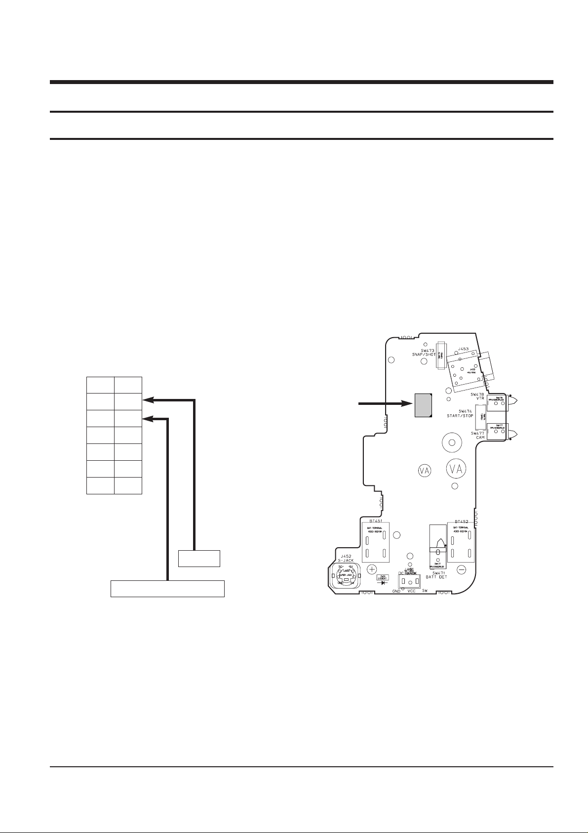
• The location of test point (See Fig.3-1)
Test Point:
PB RF - Pin 11 of CN452
Head Switching Trigger - Pin 9 of CN452
Fig. 3-2 Test location of test point (Rear Board)
Fig. 3-1 Test point
CN452
14
2
13
1
CN452
PB RF
Head Switching - Trigger
CN452
14 13
12 11
10 9
87
65
43
12
Page 2
3-2
Alignment and Adjustments
Samsung Electronics
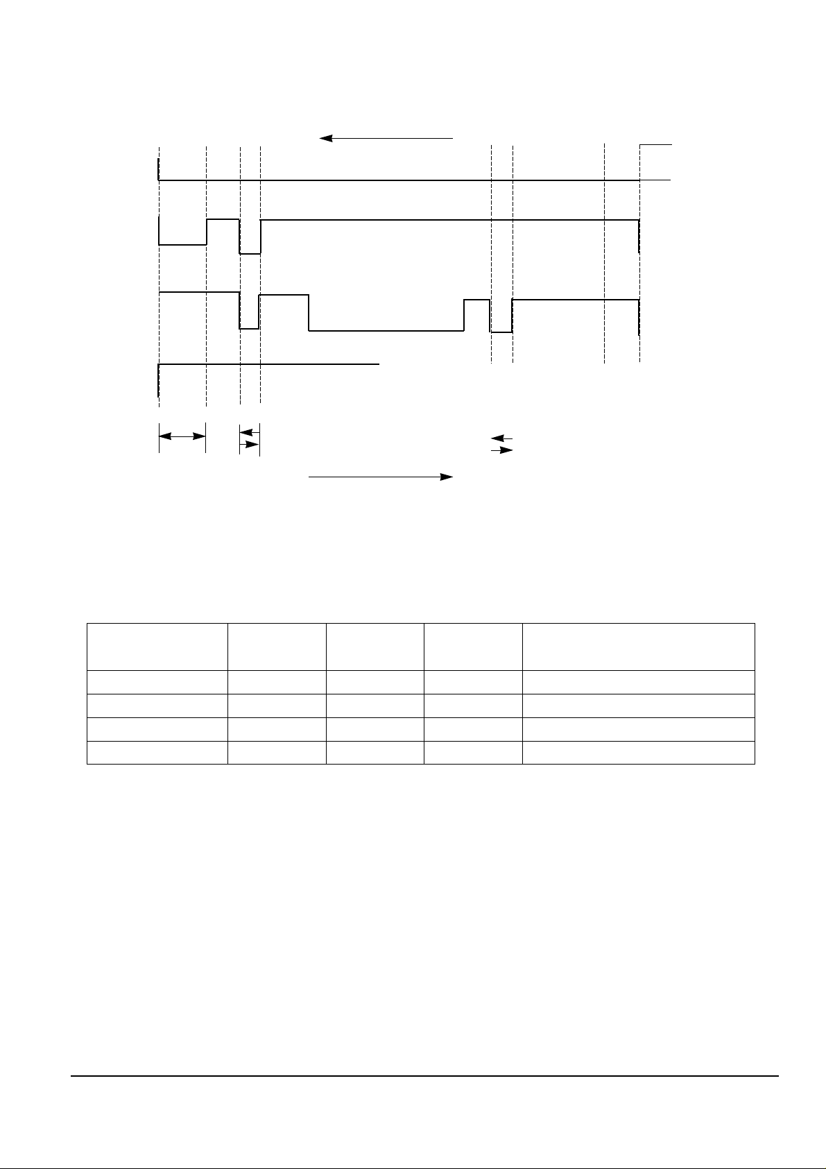
POSITION
IC601 IC601 IC601
ACTION MODE
157PIN 158PIN 159PIN
LHH EJECT
LLH UNLOADING STOP
HLL LOADING STOP
HHL PLAY, FF, REW, STILL....
EJECT
UNLOADING STOP
LOADING STOP
PB
IC601
158PIN
GROUND
IC601
159PIN
COMMON
IC601
157PIN
OPEN
EJECT
PLAY
LOADING STOP
UNLOADING
STOP
LOADING
UNLOADING
Fig. 3-3
Table. 3-1
Page 3

Alignment and Adjustments
3-3
Samsung Electronics
3-2 Camera Adjustment
Note :
1. This system has :
1) EEPROM to store the confirmed adjustment data.
2) DSP (Digital Signal Process ; ICP01 - Main board) chip to process the signal of camera parts.
3) The special mode for camera adjustment using the remote controller.
2. Keep in mind :
1) All adjustment steps should be performed using the remote controller.
3-2-1 Preparations
4. Remote control :
The following is a chart explaining the use of each button :
1. Equipment to be used :
1) DC Power supply
2) Oscilloscope
3) Frequency counter
4) Vectorscope
5) Waveform monitor
6) Color monitor or TV
7) Various charts
- Color bar chart
- Gray-scale chart, etc...
2. Composition of camera P.C.Boards :
1) Main PCB 2) CCD PCB
3) CVF PCB
3. Adjustment preparations :
1) Some buttons of set is used as a camera adjust tool.
2) Press the confirm button when each manual
adjustment step is completed to write the
adjustment data to the EEPROM.
3) After each adjustment step is completed, OSD
shows “OK!”.
4) To cancel the adjustment mode, remove the power
source.
Using Button
ENTER (CONFIRM)
P.AE (DATA UP)
DSE (DATA DOWN)
BLC (MODE UP)
FADE (MODE DOWN)
MANUAL FOCUS RING (NEAR/FAR)
ZOOM TELE
ZOOM WIDE
Adjustment
Data store after finishing adjustment by DATA UP/DOWN button.
When change data value of adjust state.
Mode change.(One step or 100 step)
Manual focus adjustment.
1) Move the zoom position of lens.
2) Semi-Auto lens adjustment.
MENU ON/OFF (MODE UP ‘100’)
Table. 3-2
Page 4
3-4
Alignment and Adjustments
Samsung Electronics
Note : In service adjustment mode, button names are different from those in customer camera function control
mode. EX) ENTER button is the same as confirm.
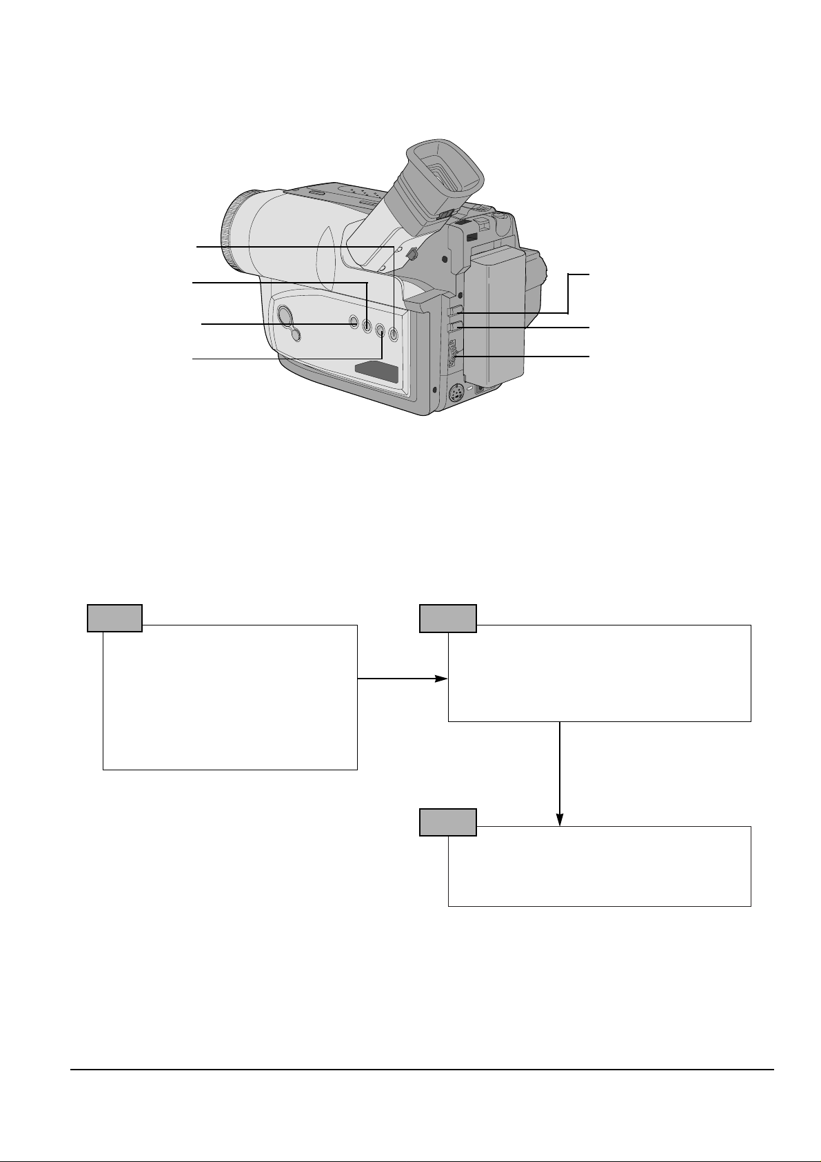
5. How to get into service “ADJUST” mode
1. Remove the lithium battery from the
camcorder.
2. Connect the power source (battery/
DC cable).
3. Eject the tape if it is in the unit.
4. Set the power switch of the
camcorder to “CAMERA” position.
STEP 1
1. Press and hold the “EJECT” button and
DATE/TIME button on the camcorder at the
same time for more than 5 seconds.
Then unit goes into service mode.
STEP 2
Note : When “XX XX” is shown in service adjustment procedures, this indicates variable values.
MENU
ON/OFF
ENTER
(MF)
UP/DOWN Dial
P
.AE
BLC
FADE
DSE
0DF.
ERR : A0 EVR : A0
STEP 3
Fig. 3-4
Page 5
Alignment and Adjustments
3-5
Samsung Electronics
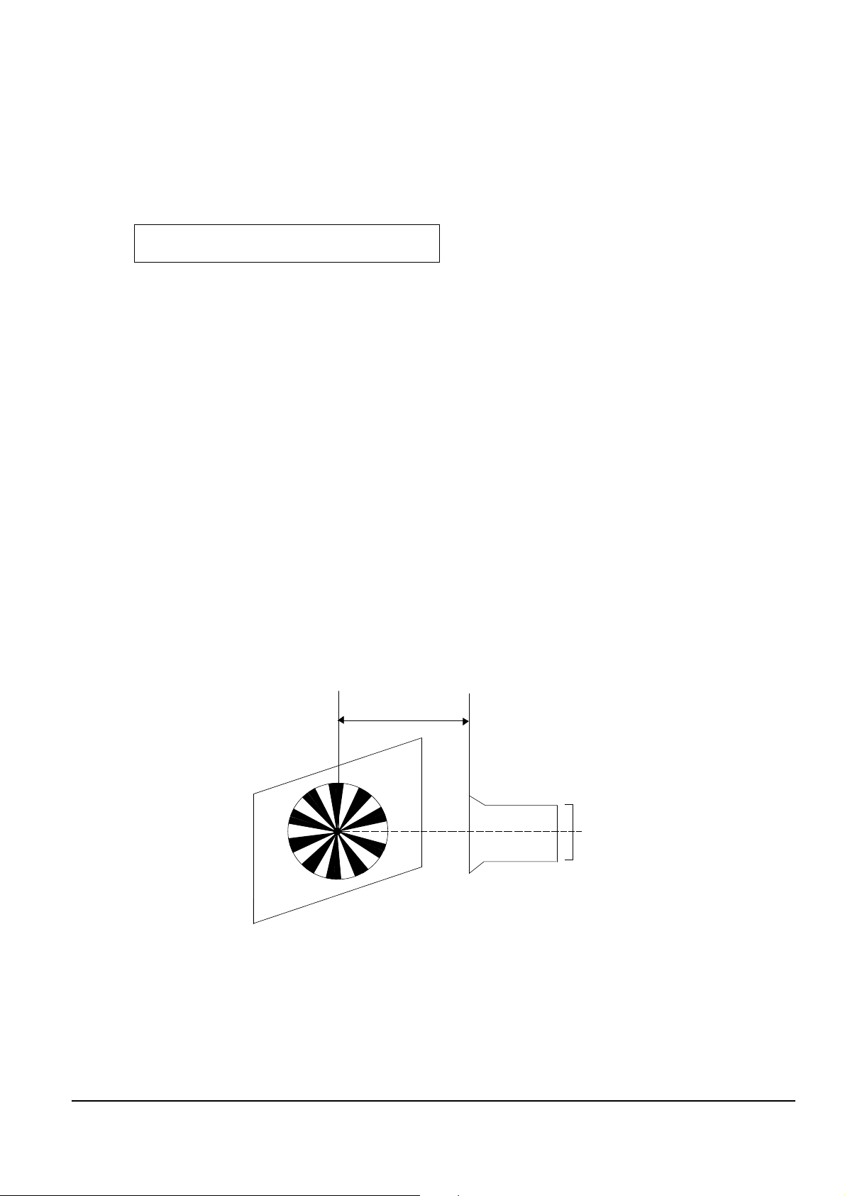
1. Focus to zoom tracking
Notes : To maintain proper focus throughout the zoom range, the focus lens position must be changed as the
zoom lens is moved.
During this adjustment the microprocessor will measure the focus positioning requirements at the wide
and telephoto position of the zoom lens.
1) Camera “E-E”.
2) Focus chart (Attached on the last page of this manual).
3) Aim the camera at the focus chart placed 3 meters away and perpendicular to the center of the lens.
The chart should be placed on the flat, gray or white wall.
4) Connect monitor TV jack to video output jack.
5) Press the “BLC(MODE UP)” and “FADE(MODE DOWN)” button, so that the OSD start is “0DE. 3M LENS XX
XX”.
6) Press “ENTER(CONFIRM)” button.
The camera will move both zoom and focus lens.
The adjustment is finished when the O.K! message appears on the TV screen.
Store the data to mode 099, 09A, 0AA, 0AB, 0AD, 0C9, 0CA, 0CB and 0CC.
3-2-2 Camera System Adjustment
Note : The on-screen display information.
“XX XX” means arbitrary value.
It can be different number depend on the conditions.
0DE XX XX
Fig. 3-5
(Be sure to maintain the distance.)
(3M±1cm)
LENS
CCD
Page 6

3-6
Alignment and Adjustments
Samsung Electronics
2. Zoom VR Center
1) Camera “E-E”, 3100°K gray-scale chart.
2) Video(output) jack and EVR.
3) Connect monitor TV to video(output) jack.
4) Press the “BLC (MODE UP)/FADE(MODE
DOWN)” button so that the OSD state is “OD6. XX
XX”.
5) Press “ENTER(CONFIRM)” button.
6) Then, the microprocessor will work ;
- Find the Zoom VR Center position
- Store the data to mode 0B7.
3. Auto hall
1) Camera “E-E”, 3100°K gray-scale chart.
2) Video(output) jack and EVR.
3) Connect monitor TV to video(output) jack.
4) Press the “BLC(MODE UP)/FADE(MODE
DOWN)” button so that the OSD state is “OCD. XX
XX”.
5) Press “ENTER(CONFIRM)” button.
6) Then, the microprocessor will work ;
- IRIS open, HALL maximum value found,
- IRIS closed, HALL minimum value found,
- IRIS open, HALL maximum value found,
- Store the data to mode 00A and mode 00B.
- Store the HALL min./max. data to mode 0C1 and
mode 0C2.
4. AUTO IRIS
1) Camera “E-E”, 3100°K gray-scale chart.
2) Video(output) jack and AF MICOM.
3) Connect video(output) jack to waveform monitor
input jack and monitor TV jack respectively.
4) Press the “BLC(MODE UP)/FADE(MODE
DOWN)” button so that the OSD state is “OCE. XX
XX”.
5) Press “ENTER(CONFIRM)” Button.
6) Then, the micro process will work;
- IRIS open, IRIS control minimum Value found.
- IRIS close, IRIS control minimum Value found.
- Store the data to mode 0B5, 0B6, 0C7 and 0C8.
7) The OSD shows “O.K”.
5. Auto white balance
1) Camera “E-E”, 3100°K/5100°K gray-scale chart.
2) Video(output) jack and AF MICOM.
4) Connect vectorscope input jack to video(output)
jack.
3) Press the “BLC(MODE UP)/FADE(MODE
DOWN)” button so that the OSD state is “OCF. XX
XX”.
a. W/B Indoor
a-1. Aim the camera at a 3100°K gray-scale chart
illuminated at 1500 to 2000 lx. (40us)
a-2. Press “ENTER(CONFIRM)” button so that the
white vector moves to the center on screen of the
vectorscope.
a-3. Store the data to mode 0A6, 0A7, 0A8, 0A9
a-4. The OSD shows “OK!”.
b. W/B Outdoor
b-1. Aim the camera at a 5100°K gray-scale
(3100°K+CCB12) chart illuminated at 1500 to 2000
lx. (40us)
b-2. Press “ENTER(CONFIRM)” button so
that the white vector moves to the center on
screen of the vectorscope.
b-3. Store the data to mode 0A2, 0A3, 0A4 and 0A5.
b-4. The OSD shows “OK!”.
Center of
white level
100 IRE
Optical
black level
H
40US
Fig. 3-6
Page 7
Alignment and Adjustments
3-7
Samsung Electronics
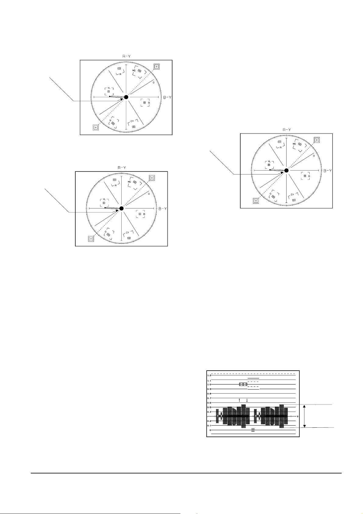
6. Pre white balance (I) ; (R-Y)
1) Camera “E-E”, 3100°K gray-scale chart.
2) Video(output) jack and AF MICOM.
3) Connect vectorscope input jack to video(output)
jack.
4) Press the “BLC(MODE UP)/FADE(MODE
DOWN)” button so that pass through 272, 273, 274,
275 and then the OSD state is “272. XX
XX(High)””273. XX XX(Low)”.
5) Aim the camera at a 3100°K gray-scale chart
illuminated at 1500 to 2000 lx.
6) Adjust the “ P.AE(DATA UP)/DSE(DATADOWN)”
button so that the white vector moves to the R-Y
axial on screen of the vectorscope.
Note : Bright dot shifts after the confirm button is
pressed.
7. Pre white balance (II) ; (B-Y)
1) Camera “E-E”, 3100°K gray-scale chart.
2) Video(output) jack and AF MICOM.
4) Connect vectorscope input jack to video(output)
jack.
3) Press the “BLC (MODE UP)/FADE(MODE
DOWN)” button so that the OSD state is “274. XX
XX(High)””275. XX XX(Low)”.
5) Aim the camera at a 3100°K gray-scale chart
illuminated at 1500 to 2000 lx.
6) Adjust the “P.AE(DATA UP) /DSE(DATADOWN)”
button so that the white vector moves to the B-Y
axial on screen of the vectorscope.
Note : Bright dot shifts after the confirm button is
pressed.
8. R-Y Gain
1) Camera “E-E”, 3100°K color bar chart.
2) Video(output) jack and register of EEPROM.
3) Connect video(output) jack to waveform monitor
input jack and monitor TV jack respectively.
4) Press the “BLC(MODE UP)/FADE(MODE
DOWN)” button so that the OSD state is “280. XX
XX(High)””281. XX XX(Low)”.
5) Aim the camera at a color bar chart illuminated at
1500 to 2000 lx.
6) Adjust the “P.AE(DATA UP)/DSE(DATA
DOWN)” button so that the red level is
NTSC : 70IRE, PAL : 500mV
7) Be sure to press the “ENTER(CONFIRM)” button to
memorize setting.
Note : Bright dot shifts after the confirm button is
pressed. (outdoor : 034, 035)
Match the white luminance
point with the
black luminance
point
Match the white luminance
point with the
black luminance
point
Fig. 3-7
Fig. 3-8
Match the white luminance
point with the
black luminance
point
Fig. 3-9
70 IRE (NTSC)
500mV (PAL)
Fig. 3-10
Page 8

3-8
Alignment and Adjustments
Samsung Electronics
9. B-Y Gain
1) Camera “E-E”, 3100°K color bar chart.
2) Video(output) jack and register of EEPROM.
3) Connect video(output) jack to waveform monitor
input jack and monitor TV jack respectively.
4) Press the “BLC(MODE UP)/FADE(MODE
DOWN)” button so that the OSD state is “283. XX
XX(High)””284. XX XX(Low)”.
5) Aim the camera at a color bar chart illuminated at
1500 to 2000 lx.
6) Adjust the “P.AE(DA TA UP)/DSE(DATA DOWN)”
button so that the blue level is NTSC :
50IRE, PAL : 350mV
7) Be sure to press the “ENTER(CONFIRM)” button to
memorize setting.
Note : Bright dot shifts after the confirm button is
pressed.
(outdoor : 036, 037)
10. R-Mg Hue
1) Camera “E-E”, 3100°K color bar chart.
2) Video(output) jack and register of EEPROM.
3) Connect video(output) jack to vectorscope input
jack and monitor TV jack respectively.
4) Press the “BLC(MODE UP)/FADE(MODE
DOWN)” button so that the OSD state is “284. XX
XX(High)””285. XX XX(Low)”.
5) Aim the camera at a color bar chart illuminated at
1500 to 2000 lx.
6) Adjust the “P.AE(DA TA UP)/ DSE(DA TA DOWN)”
button so that theRed vector is 105.
7) Be sure to press the “ENTER (CONFIRM)” button
to memorize setting.
Note : Bright dot shifts after the confirm button is
pressed.
(outdoor : 038, 039)
11. G-Cy Hue
1) Camera “E-E”, 3100°K color bar chart.
2) Video(output) jack and register of EEPROM.
3) Connect video(output) jack to vectorscope input
jack and monitor TV jack respectively.
4) Press the “BLC(MODE UP)/FADE(MODE
DOWN)” button so that the OSD state is “286. XX
XX(High)””287. XX XX(Low)”.
5) Aim the camera at a color bar chart illuminated at
1500 to 2000 lx.
6) Adjust the “P.AE(DATA UP)/ DSE(DATADOWN)”
button so that the Cyan vector is 284.
7) Be sure to press the “ENTER (CONFIRM)” button
to memorize setting.
Note : Bright dot shifts after the confirm button is
pressed.
(outdoor : 03A, 03B)
Fig. 3-12
50 IRE (NTSC)
350mV (PAL)
RED VECTOR
105 DEG.
Fig. 3-11
CYAN VECTOR
284 DEG.
Fig. 3-13
Page 9

Alignment and Adjustments
3-9
Samsung Electronics
12. B-Cy-Mg Hue
1) Camera “E-E”, 3100°K color bar chart.
2) Video(output) jack and register of EEPROM.
3) Connect video(output) jack to vectorscope input
jack and monitor TV jack respectively.
4) Press the “BLC(MODE UP)/FADE(MODE
DOWN)” button so that the OSD state is “288. XX
XX(High)””289. XX XX(Low)”.
5) Aim the camera at a color bar chart illuminated at
1500 to 2000 lx.
6) Adjust the “P.AE (DATA UP)/ DSE(DATA
DOWN)” button so that the Blue vector is 346.
7) Be sure to press the “ENTER (CONFIRM)” button
to memorize setting.
Note : Bright dot shifts after the confirm button is
pressed.
(outdoor : 03C, 03D)
13. Ye-G Hue
1) Camera “E-E”, 3100°K color bar chart.
2) Video(output) jack and register of EEPROM.
3) Connect video(output) jack to vectorscope input
jack and monitor TV jack respectively.
4) Press the “BLC(MODE UP)/FADE(MODE
DOWN)” button so that the OSD state is “28A.XX
XX(High)””28B.XX XX(Low)”.
5) Aim the camera at a color bar chart illuminated at
1500 to 2000 lx.
6) Adjust the “P.AE(DA TA UP) /DSE(DA TA DOWN)”
button so that the Yellow vector is 165.
7) Be sure to press the “ENTER(CONFIRM)” button to
memorize setting.
Note : Bright dot shifts after the confirm button is
pressed.
(outdoor : 03E, 03F)
Note : Outdoor(5100°K) color Gain & Hue adjust.
- 5100°K color bar (or 3100°K color bar with
CCB12 Filter)
- Restart step 7. prewhite balance(I) ~ step 14.
Ye-G Hue.
- The outdoor(5100°K) mode in 034~03F.
BLUE VECTOR
346 DEG.
Fig. 3-14
YELLOW VECTOR
165 DEG
Fig. 3-15
Page 10

3-10
Alignment and Adjustments
Samsung Electronics
1. Equipment :
1) Monitor TV.
2) Dual trace oscilloscope of over 20MHz band,
incorporates delay mode.
(Use 10 : 1 probe unless otherwise specified.)
3) Frequency counter
4) DC power supply.
5) Alignment tape (Colour bar : SP)
6) 8mm Video Tape for record.
2. Composition of VCR P.C.Boards
1) Main PCB (system control/servo, video, audio,
camera)
2) Rear PCB
3) Front PCB
4) Function PCB
3. How to get into service “ADJUST” mode.
3-3-1 Peraration
1. Connect the power source (battery/DC cable).
2. Set the program selector of the camcorder to PLAYER
position.
3. Press the eject key to eject mode.
STEP 1
1. Press and hold “STOP” and “EJECT” button on the
Camcorder at the same time for more than 5 seconds.
2. If the adjustment mode displayed like the figure below,
VCR adjustment mode has been successfully activated.
3. Insert tape into housing ass’y and then perform the
adjustments.
STEP 2
061.
EPR:XX EVR:XX
TV or CVF monitor
Address of the adjustment mode.
: there are 061h to 1 ch.(refer xxxx)
Name of the adjustment mode.
: every address have a name like this (refer
xxx)
Present data
: be adjusted before.
New data
: be adjusted newly.
3-3 VCR Adjustment
Fig. 3-16
Page 11

4. The location of function button.
5. If you want to finish the adjustment mode, you have to do “Battery Reset”.
The “Battery Reset” means that you pull out the power source and pull in it again.
Then, the adjustment is ended and the camcorder works normally.
Alignment and Adjustments
3-11
Samsung Electronics
Note :
In service adjustment mode, button names are different from those in customer function control mode.
EX) “ENTER” button is the same as “CONFIRM”.
MENU
ON/OFF
ENTER
(MF)
UP/DOWN Dial
P
.AE
BLC
FADE
DSE
Fig. 3-17
Page 12

3-12
Alignment and Adjustments
Samsung Electronics
Note 2 : How to connect video out signal.
-Connect the video cable to ass’y A/V Jack.
3-3-2 VCR Section
Note 1 : From this point forward, the structure of every adjustment is as follows.
Test point
Step Adjustment Item
1. Mode and input signal/
alignment tape
2. Test point and ADJ. part
3. Result and Remarks
ADJ. point
Fig. 3-18 Video Signal Connection
14
13
VIDEO OUT
12
11
10
9
8
7
6
5
4
3
2
1
NC
PB RF
AUDIO OUT
HD SW
VCR UNREG
JIG CS
VCR UNREG
JIG SCK
SS GND
JIG SO
JIG DETECT
JIG SI
AUDIO GND
14
MAIN PCB
REAR PCB
FRONT PCB
CN452
13
12
11
10
9
8
7
6
5
4
3
21
Page 13

Alignment and Adjustments
3-13
Samsung Electronics
3-4 DECK Adjustment
3-4-1 Operation Without Housing Assembly
Fig. 3-20
Fig. 3-19
1. Remove the Housing Ass’y from the recorder unit.
2. Connect the mechanical chassis to the recorder circuit to supply voltage.
3. Set to Unload mode.
4. Press the S/W Push (Keep ON status) and make
loading.
5. Push the Play key.
Drum side Opposite side Movement of Chassis
+–Loading
–+Unloading
Table 3-3
3-4-2 Setting Mechanical Mode (Without Recorder Circuit)
1. Set the power-supply output to approx. 3V.
2. Choose the polarity (depending on whether loading
or unloading).
3. Supply the voltage to the Motor Loading, and set to
the desired mode.
Note : For the removals of the Housing Ass’y, refer to the
page 4-7.
S/W PUSH
CONNECTED TO THE
RECORDER CIRCUIT
Page 14

3-14
Alignment and Adjustments
Samsung Electronics
Fig. 3-21
Carry out the following periodic maintenance checks
in order not only to fully exhibit the functions and
operate the set, but also for the equipment and tape.
After repairing, service the set as follows :
1) Cleaning of Drum Assembly
1. Gently apply lens tissue soaked in ethyl alcohol to
the Drum assembly.
Clean the Upper Drum assembly while rotating it
slowly counterclockwise (by hand).
2) Cleaning of Tape Path
1. In EJECT mode, clean the tape path system (from
Pole Tension P1 through Pole Review P7, Pinch
Roller and Capstan Shaft) and the Lower Drum.
Using the lens tissue soaked in ethyl alcohol.
Note : Do not rotate the motor by power or rotate the Upper
Drum assembly clockwise. Also, the Head tip will be damaged if
the lens tissue is moved in a perpendicular direction.
Be sure to follow these instructions when cleaning the Drum
Ass’y.
Note : Make sure that no oil or grease adheres to the lens tissue.
P3
P1
P2
P6
P4
P7
PINCH
ROLLER
P5
3-4-3 Maintenance
Page 15

Alignment and Adjustments
3-15
Samsung Electronics
3) Periodic Maintenance and Check List
When overhauling, refer to the following table.
◆ When lubricating bearings, be sure to keep the oil free
of dust. (Oil contaminated with dust might cause the
bearings to wear out or seize.)
◆ A “drop” of oil is defined as the amount attached to
the tip of a ø 2mm stick as shown in Fig. 3-22.
Maintenance and check items
Hours of use (H)
Remarks
500 1000 1500 2000 2500 3000 3500 4000 4500 5000
Tape path Cleaning of tape path
OOOOOOOOOO
system
Cleaning and degaussing
OOOOOOOOOO
of drum assembly
Capstan Shaft
∆∆∆∆∆
Gear Capstan
∆∆∆∆∆
Driving system Gear Pulley Shaft
∆∆∆∆∆
Belt Timing
◆◆◆◆◆
Motor Loading
◆◆◆◆◆
Performance Abnormal noise
◆◆ ◆◆◆◆◆◆◆
Back tension measurement
◆◆◆◆◆
Confirmation Brake system
◆◆◆◆◆
PB, REV torque
◆◆◆◆◆
measurement
Table 3-4
Fig. 3-22
Be absolutely careful not to get oil on
the tape path sur-
face.
O : Cleaning ∆ : Oil ◆ : Confirmation
OIL
ø 2mm
Page 16

3-16
Alignment and Adjustments
Samsung Electronics
Fig. 3-23
1) Tension Regulator Adjustment
(A) DISASSEMBLY
1. Refer to the page 2-7 to remove the Housing Ass’y.
(B) ADJUSTMENT
1. Set to PB mode (without cassette tape).
2. Check that the overlap between external surface of
Chassis Sub and external surface of Arm Tension is
0 ~ 1mm. (Fig. 3-23)
3. If necessary, proceed to step 4.
4. If the Arm Tension 1 is located inside the position
specified, adjust the Band Adjust Tension 2 toward
arrow A.
If it is located outside, adjust toward arrow B.
(C) REASSEMBLY
1. Refer tothe page 2-7 to mount the Housing Ass’y.
Hole of Holder Loading
ARM TENSION 1
BAND ADJUST TENSION 2
C
B
A
0~1mm
Note :
Check if the arm tension can be moved toward arrow C in
PB mode. Use the tape which is fed to the end.
3-4-4 Mechanical Check and Adjustment
Page 17

Alignment and Adjustments
3-17
Samsung Electronics
Fig. 3-24
2) Back Tension Adjustment
1. Set up the cassette-torque tape.
2. Set to PB mode and check that the torque value of
Reel S is 9 ± 1.5g.cm.
(If necessary, proceed to step 3 or 4).
3. If the value is too high : While pushing the adjustment claw (rack shape) of Slider Tension toward
arrow C, shift the meshing position (with the claw
of Slider Tension toward arrow A).
See Fig. 3-24.
4. If the value is too low : While pushing the adjust
ment claw (rack shape) of Slider Tension toward
arrow C, shift the meshing position (with the claw
of Slider Tension toward arrow B).
See Fig. 3-24.
3) PB/REV Torque Check
1. Set up the cassette torque tape.
2. Set to PB mode, and check that the torque vlaue of
Reel T is 9 ± 3g.cm.
3. Set to REV mode, and check that the torque value of
Reel S is 25 ± 5g.cm.
4. If necessary, replace the defective reel assembly.
Note : When shifting the position of hooks, remove the cassette
torque tape.
* Remarks : If the cassette torque tape is recorded both in the LP/SP modes by mistake, the torque at the switching point
between SP/LP modes becomes unstable. In that case, do the torque adjustment in REC mode.
Page 18

3-18
Alignment and Adjustments
Samsung Electronics
REEL S TABLE
RESTING SURFACE
SUB CHASSIS
REEL T TABLE
RESTING SURFACE
Fig. 3-25
4) Reel Table Height Check
(A) REMOVAL
1. Refer to the page 2-7
; Remove the Housing Ass’y.
2. Refer to the page 2-9
; Remove the Idler Ass’y.
(B) CHECK
1. Using the slide calipers, check the following dis-
tances: The upper surface of the P.C.B Reel to the
Reel S table resting surface and the Reel T table resting surface should each be 5.7 ± 0.2mm.
(C) MOUNTING
1. Refer to the page 2-9
; Mount the Idler Ass’y.
2. Refer to the page 2-7
; Mount the Housing Ass’y.
Page 19

Alignment and Adjustments
3-19
Samsung Electronics
Fig. 3-27
1) Preparation for Adjustment
1. Clean the tape running surface (Poles, Drum,
Capstan Shaft, Pinch Roller).
2. Refer to the Service Manual (of camcorder).
Observe the PB RF signal and Head Switching
Pulse on an oscilloscope.
3. Play back the alignment tape.
4. Check that the waveform of the RF signal is flat
both at the inlet and outlet (Fig. 3-26 A).
If not flat (B or C in Fig. 3-26), do adjustments
2) through 5).
Fig. 3-26
REEL S
REEL T
A CORRECT
B DEFECT AT INLET
C DEFECT AT OUTLET
INLET OUTLET
3-4-5 Tape Path Adjustment
Page 20

3-20
Alignment and Adjustments
Samsung Electronics
2) Tracking Adjustment
1. Play back the alignment tape. (Tracking B or C)
2. Turn P2 to flatten the waveform at the inlet.
3. Turn P5 to flatten the waveform at the outlet.
Fig. 3-28
P2
P5
3) Not Adjustment
1. Play back the alignment tape, and confirm that the
tape is not loosened between the Capstan Motor
and Cuide Roller T.
2. Set to REV mode and observe the outlet waveform
of PB RF signal. (Fig. 3-30)
Fig. 3-29
GUIDE
ROLLER S
(P2)
TAPE SHOULD NOT BE
LOOSENED HERE
P7 CAPSTAN
GUIDE ROLLER T (P5)
Fig. 3-30
(NG) (GOOD)
Page 21

Alignment and Adjustments
3-21
Samsung Electronics
4) Check After Adjustment
(A) TRACKING CHECK
1. Play back the alignment tape.
2. Then, Confirm that the minimum amplitude value
(E min.) is 65% of the maximum value
(E max.) or larger. (Fig. 3-31)
3. Confirm that no large fluctuations occur on the
waveform. (Fig. 3-32)
Fig. 3-31
E
MIN EMAX
E
MIN
65(%)
E
MAX
(B) CUE AND REV CHECK
1. Play back the alignment tape, and set to REV mode.
Confirm that the waveform peaks have a uniform
pitch. (Fig. 3-33 )
2. Set to CUE mode.
Confirm that the waveform peaks still have a uniform pitch. (Fig. 3-33 )
Fig. 3-33
a b c
a b c
Fig. 3-32
A
C
C
C
1
A
8
a = b = c
A
>
=
B
<
=
A
Page 22

3-22
Alignment and Adjustments
Samsung Electronics
(C) RISE TIME CHECK
1. Play back the alignment tape.
2. Set to playback mode, and confirm that the waveform of PB RF signal rises flatly within 3 seconds.
Also confirm that the tape is not
loosened or curled around the Pinch Roller.
(Fig. 3-34)
3. Run the tape in CUE/REV and FF/REW modes,
then playback. Confirm the waveform of PB RF signal rises flatly within 3 seconds.
Also confirm that the tape is not loosened or curled
around the Pinch Roller.
4. Repeat steps 2. and 3.
(D) TAPE PATH CHECK
1. In CUE and REV modes, check that the tape is not
too curled around the P2 Upper Flange,
P5 Upper Flange, and P7 Upper/Lower Flanges.
(Fig. 3-35)
Fig. 3-34
Fig. 3-35
GUIDE
ROLLER T
TAPE SHOULD NOT BE
LOOSENED OR CURLED HERE
FROM THE REEL S TO THE REEL T
P7
P2
P5 P7
CAPSTAN
 Loading...