

Samsung SND-1011 User Manual

NETWORK CAMERA
User Manual
SND-1011

Network Camera
User Manual
Copyright
©2011 Sams ung Techwin Co ., Ltd. All rig hts reser ved.
Trad em ark
The name of thi s product is the reg istered tradema rk of Samsung Techwin C o., Ltd.
Other trad emarks mention ed in this manual are t he registered trad emark of their res pective compan y.
Restriction
Samsung Techwi n Co., Ltd shall reser ve the copyrigh t of this document. U nder no circumst ances, this docu ment shall
be reproduc ed, distribute d or changed, par tially or wholly, wit hout formal auth orization of Sa msung Techwin.
Disclaimer
Samsung Techwi n makes the best to ve rify the integr ity and correc tness of the conte nts in this documen t, but no
formal guar antee shall be provi ded. Use of this do cument and the subs equent results sh all be entirely on the u ser’s own
responsib ility. Samsung Techwi n reserves the ri ght to change the con tents of this docu ment without pri or notice.
Design an d specificat ions are subjec t to change wit hout prior not ice.
The defau lt password c an be exposed to a h acking threa d so it is recommen ded to change th e password
after in stalling the p roduct.
Note that t he security a nd other relat ed issues caus ed by the unchan ged password s hall be respon sible
for the user.
is the regist ered logo of Samsun g Techwin Co., Ltd.
overview
IMPORTANT SAFETY INSTRUCTIONS
1. Read these instructions.
2. Keep these instructions.
3. Heed all warnings.
4. Follow all instructions.
5. Do not use this apparatus near water.
6. Clean only with dry cloth.
7. Do not block any ventilation openings, Install in accordance with the manufacturer’s
instructions.
8. Do not install near any heat sources such as radiators, heat registers, stoves, or other
apparatus (including amplifiers) that produce heat.
9. Do not defeat the safety purpose of the polarized or grounding-type plug. A polarized
plug has two blades with one wider than the other. A grounding type plug has two
blades and a third grounding prong. The wide blade or the third prong are provided for
your safety. If the provided plug does not fit into your outlet, consult an electrician for
replacement of the obsolete outlet.
10. Protect the power cord from being walked on or pinched particularly at plugs,
convenience receptacles, and the point where they exit from the apparatus.
11. Only use attachments/ accessories specified by the manufacturer.
12. Use only with the cart, stand, tripod, bracket, or table specified by
the manufacturer, or sold with the apparatus. When a cart is used,
use caution when moving the cart/apparatus combination to avoid
injury from tip-over.
13. Unplug this apparatus during lighting storms or when unused for
long periods of time.
14. Refer all servicing to qualified service personnel. Servicing is required when the
apparatus has been damaged in any way, such as power-supply cord or plug is
damaged, liquid has been spilled or objects have fallen into the apparatus, the apparatus
has been exposed to rain or moisture, does not operate normally, or has been dropped.
● OVERVIEW
English _3
overview
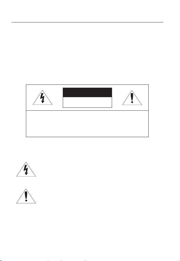
WARNING
TO REDUCE THE RISK OF FIRE OR ELECTRIC SHOCK, DO NOT EXPOSE
THIS PRODUCT TO RAIN OR MOISTURE. DO NOT INSERT ANY METALLIC
OBJECT THROUGH THE VENTILATION GRILLS OR OTHER OPENNINGS
ON THE EQUIPMENT.
Apparatus shall not be exposed to dripping or splashing and that no objects
filled with liquids, such as vases, shall be placed on the apparatus.
CAUTION
CAUTION
RISK OF ELECTRIC SHOCK.
DO NOT OPEN
CAUTION
REFER SERVICING TO QUALIFIED SERVICE PERSONNEL.
: TO REDUCE THE RISK OF ELECTRIC SHOCK.
DO NOT REMOVE COVER (OR BACK).
NO USER SERVICEABLE PARTS INSIDE.
EXPLANATION OF GRAPHICAL SYMBOLS
The lightning flash with arrowhead symbol, within an
equilateral triangle, is intended to alert the user to the
presence of “dangerous voltage” within the product’s
enclosure that may be of sufficient magnitude to constitute a
risk of electric shock to persons.
The exclamation point within an equilateral triangle is intended
to alert the user to the presence of important operating
and maintenance (servicing) instructions in the literature
accompanying the product.
4_ overview

Class construction
An apparatus with CLASS construction shall be connected to a MAINS
socket outlet with a protective earthing connection.
Battery
Batteries(battery pack or batteries installed) shall not be exposed to excessive
heat such as sunshine, fire or the like.
Disconnection Device
Disconnect the main plug from the apparatus, if it’s defected. And please call
a repair man in your location.
When used outside of the U.S., it may be used HAR code with fittings of
an approved agency is employed.
CAUTION
These servicing instructions are for use by qualified service personnel only.
To reduce the risk of electric shock do not perform any servicing other than
that contained in the operating instructions unless you are qualified to do so.
The BNC Out terminal of the product is provided for easier installation, and is
not recommended for monitoring purposes.
If you keep the BNC cable connected, a risk of lightening may cause damage
or malfunction to the product.
Please use the input power with just one camera and other devices must not
be connected.
● OVERVIEW
English _5

overview
Please read the following recommend safety precautions carefully.
Do not place this apparatus on an uneven surface.
Do not install on a surface where it is exposed to direct sunlight, near
heating equipment or heavy cold area.
Do not place this apparatus near conductive material.
Do not attempt to service this apparatus yourself.
Do not place a glass of water on the product.
Do not install near any magnetic sources.
Do not block any ventilation openings.
Do not place heavy items on the product.
User’s Manual is a guidance book for how to use the products.
The meaning of the symbols are shown below.
Reference : In case of providing information for helping of product’s usages
Notice : If there’s any possibility to occur any damages for the goods and
human caused by not following the instruction
Please read this manual for the safety before using of goods and keep it in
the safe place.
6_ overview

CONTENTS
OVERVIEW
3
INSTALLATION &
CONNECTION
13
NETWORK CONNECTION
AND SETUP
21
3 Important Safety Instructions
9 Product Features
9 Recomended PC Specifications
10 Recomended
Memory Card Specifications
10 What’s Included
11 At a Glance
13 Installation
16 Inserting/Removing an SD
Memory Card
18 Memory Card Information
(Not Included)
18 Connecting with other Device
21 Connecting the Camera Directly
to Local Area Networking
22 Connecting the Camera Directly
to a DHCP Based DSL/Cable
Modem
23 Connecting the Camera Directly
to a PPPoE Modem
24 Connecting the Camera to a
Broadband Router with the
PPPoE/Cable Modem
25 Buttons used in IP Installer
26 Static IP Setup
30 Dynamic IP Setup
31
Port Range Forward (Port Mapping)
Setup
33 Connecting to the Camera from a
Shared Local PC
33 Connecting to the Camera from a
Remote PC via the Internet
Micro SD/SDHC
● OVERVIEW
English _7

overview
WEB VIEWER
34
SETUP SCREEN
44
APPENDIX
71
34 Connecting to the Camera
35 Login
36 Installing ActiveX
37 Installing Silverlight Runtime
39 Using the Live Screen
41 Playback (Event)
42 Playback (Time)
44 Setup
44 Video Setup
52 Network Setup
59 Event Setup
66 System Setup
71 Specification
75 Product Overview
76 Troubleshooting
78 Open Source Announcement
80 GPL/LGPL Software License
8_ overview

PRODUCT FEATURES
• Multi-Streaming
This network camera can display videos in different resolutions and qualities
simultaneously using different CODECs.
• Web Browser-based Monitoring
Using the Internet web browser to display the image in a local network environment.
• Alarm
If an event occurs, the event-related video will be transferred to the email specified by the
user, or saved to the SD memory.
• Video Motion Detection
Detects a motion from the video before triggering an event.
• Face Detection
Recognizes a face from the camera input video, or transfers a clearer image of your specified
area.
• Auto Detection of Disconnected Network
Detects network disconnection before triggering an event.
• ONVIF Compliance
For more information, refer to www.onvif.org.
RECOMENDED PC SPECIFICATIONS
• CPU : Intel(R) Core(TM)2 2.4 GHz or higher
• Operating System : Windows XP, VISTA, 7
• Resolution : 1280X1024 pixels or higher
• RAM : 2GB or higher
• Web Browser :
Safari 4.0 or later
Neither a beta test version unlike the version released in the company website nor the developer version will
be supported.
It is recommended to connect to IPv6 in Windows 7.
Mac OS
Internet Explorer 7.0 or later, Firefox 3.0 or later, Chrome 8.0 or later,
● OVERVIEW
English _9
overview
• Video Memory : 256MB or higher
If the driver of the video graphic adapter is not installed properly or is not the latest version, the
J
video may not be played properly.
For a multi-monitoring system involving at least 2 monitors, the playback performance can be
deteriorated depending on the system.
RECOMENDED MICRO SD/SDHC MEMORY CARD
SPECIFICATIONS
• 2GB ~ 32GB
• To ensure proper recording of video data, it is recommended you use a memory card that
supports at least read/write speed 10Mbps and Class 6.
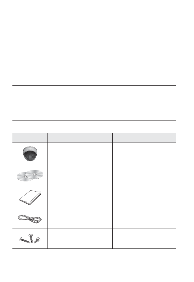
WHAT’S INCLUDED
Please check if your camera and accessories are all included in the product package.
Appearance Item Name Quantity Description
Camera 1
User Manual,
Installer S/W CD,
CMS S/W DVD
Quick Guide 1
2
10_ overview
Cable for the testing monitor 1
Iron Screw 3 Used for fixing to an iron plate
Used to test the camera connection to a
portable display device
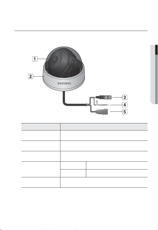
AT A GLANCE
Appearance
Item Description
Dome Cover Dome cover for the lens and unit protection.
Main unit Main unit includes the lens, switch board, PCB boards and screws.
b
Power Port Used to plug the power cable.
c
Alarm Input Port
● OVERVIEW
BROWN = Alarm IN Used to connect the alarm input sensor.
BLACK = GND Used for earth-grounding.
Network Port Used to connect a PoE or LAN cable.
English _11
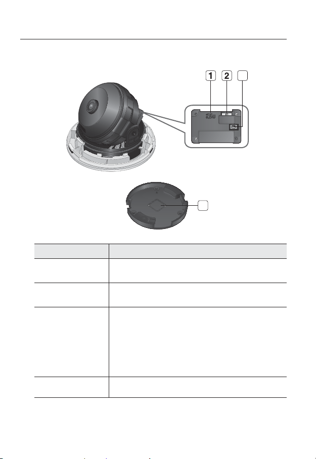
overview
RESETRESET
VIDEO
OUT
Components
Item Description
Micro SD Memory
Card Compartment
Monitor Out
b
Reset Button
c
3
FRONT
4
Compartment for the
Using the test monitor cable, you can connect to a mobile display for camera
(for installation)
test.
Resets the camera settings to the default.
Press and hold for about 5 seconds to reboot the system.
If you reset the camera, the network settings will be adjusted so that
J
DHCP can be enabled. If there is no DHCP server in the network, you
must run the IP Installer program to change the basic network settings
such as IP address, Subnet mask, Gateway, etc., before you can
connect to the network.
Micro SD memory card.
Wiring Cover Arrange the cables through this hole.
12_ overview
installation & connection
INSTALLATION
Precautions before installation
Ensure you read out the following instructions before installing the camera:
• Select an installation site (ceiling or wall) that can endure at least 5 times of the camera
weight.
• Stuck-in or peeled-off cables can cause damage to the product or a fire.
• For safety purposes, keep anyone else away from the installation site.
And put aside personal belongings from the site, just in case.
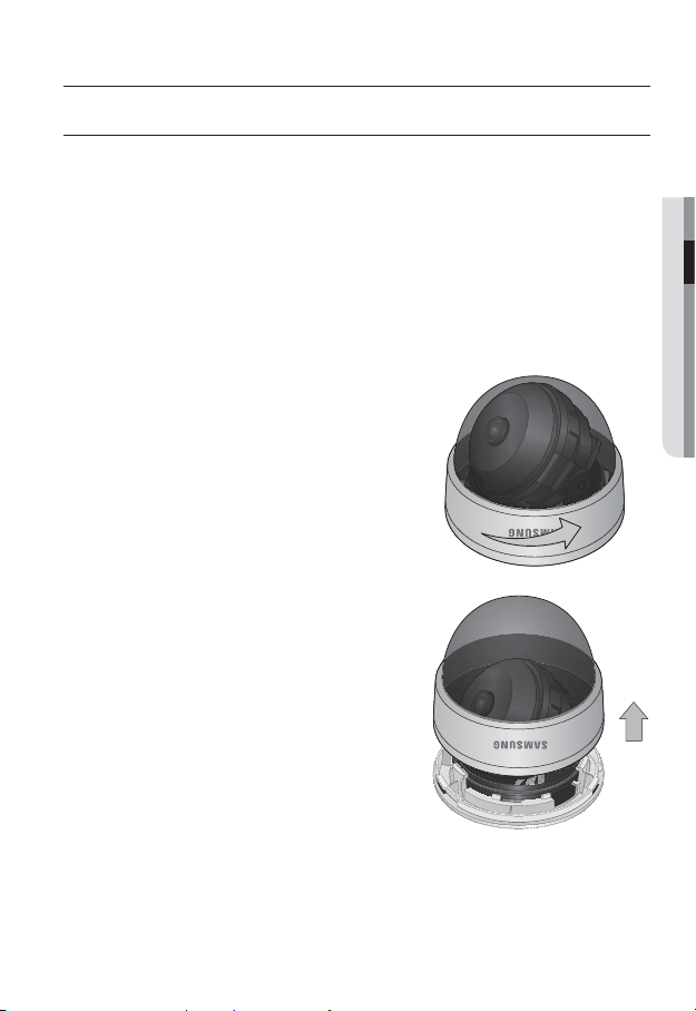
Installing the camera
1. Use one hand to hold the camera’s bottom
part and turn the cover counterclockwise
with another hand to separate it.
Removing the cover reveals the main unit.
● INSTALLATION & CONNECTION
English _13
installation & connection
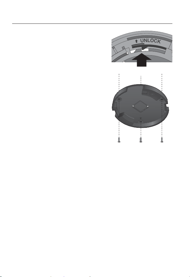
2.
Turn the bracket counterclockwise while pressing
the locker ratchet outwards to separate it.
3. Use the provided screws (x3) to fix the bracket
to a desired position (ceiling or wall).
Ensure that the <FRONT> label on the bracket faces
the direction for camera monitoring.
4. Arrange the cables through the bracket to
the ceiling or wall.
If you intend to drill a hole in the installation
site for the wiring purpose, remove the wiring
cover by force to reveal a hole. Arrange the
cables through the hole. If you intend to
arrange the cables without drilling a hole, use
the empty area opposite to the <FRONT>
label side for the wiring purpose.
5. Mount the main unit onto the bracket.
Align the marking hole of the main unit with
FRONT> label of the bracket, and turn
the <
the unit in the <LOCK> direction.
6. Adjust the lens in a desired direction.
For adjusting the lens direction, refer to
“Adjusting the monitoring direction for the camera”. (page 15)
7. Fix the cover to the main unit.
Fit the protruding part inside the cover into the corresponding hole of the main unit,
and turn the cover to fix it.
Wiring Cover
FRONT
14_ installation & connection
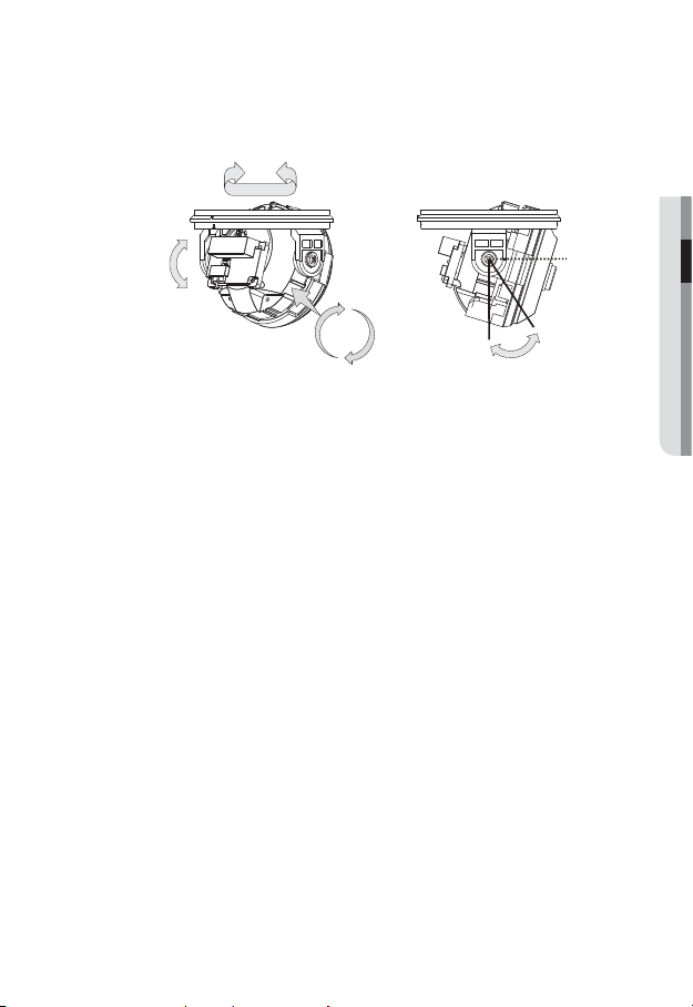
Adjusting the monitoring direction for the camera
Panning
● INSTALLATION & CONNECTION
Tilting
Lens rotation
❖Adjusting the monitoring direction
You can adjust the camera direction only when the camera is fixed on the ceiling.
Then, turning the camera to the left or right is referred to as “Panning”, while tilting the
angle is “Tilting”. For panning, the panning limit is
counterclockwise, a total of
- Adjust the panning angle so that the camera settles in the right horizontal position.
You can adjust the panning up to
direction, a total of
- Adjust the tilting angle so that the camera settles in the right vertical position. You can
adjust the tilting between
- The total rotation range is 355°. You can make adjustment in one direction up to
125°, and 230° in the other direction.
❖Methods of adjustment
• The case of wall installation
①
After mounting the camera on the wall, adjust the panning angle so that the camera
faces a desired direction when tilting.
②
Adjust the Rotate position to fit the video to the screen borders.
③
Then, adjust the tilting angle so that the camera faces the monitoring direction.
• The case of ceiling installation
①
After mounting the camera on the ceiling, adjust the panning angle according to
the monitoring direction. You should adjust the panning angle lest that the video be
displayed upside down on the monitor.
②
Adjust the Rotate position to fit the video to the screen borders.
③
Then, adjust the tilting angle so that the camera faces the monitoring direction.
For smoother Rotate adjustment, set the Tilt position between 60° ~ 80°.
J
352° enabled; further rotation is stopped by the stopper.
176° in each one direction, and 176° in the other
352°.
0° and 90°.
176° for the clockwise, and 176° for the
0˚
0˚ ~ 90˚
English _15
installation & connection
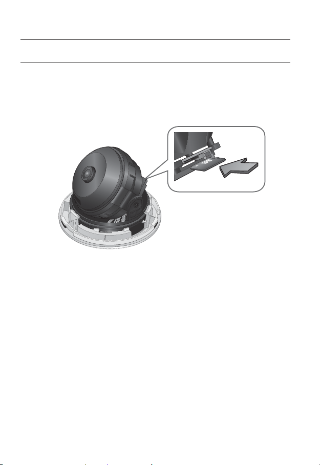
INSERTING/REMOVING AN SD MEMORY CARD
Disconnect the power cable from the camera before inserting the SD memory card.
J
Inserting an SD Memory Card
Push the SD memory card in the direction of the arrow shown in the diagram.
Do not insert the SD memory card while it’s upside down by force. Otherwise, it may damage the
J
SD memory card.
16_ installation & connection
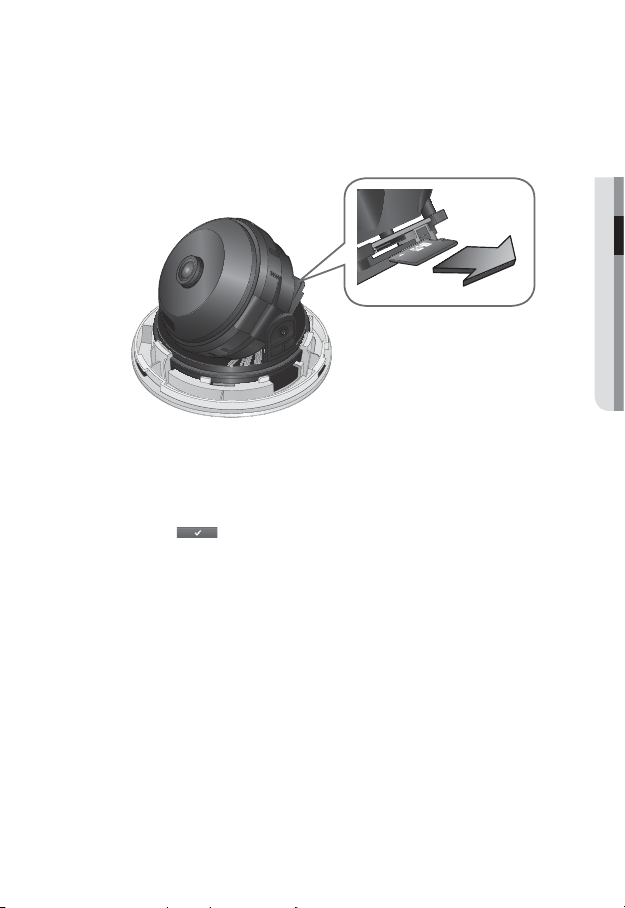
Removing an SD Memory Card
Gently press down on the exposed end of the memory card as shown in the diagram to
eject the memory card from the slot.
Pressing too hard on the SD memory card can cause the card to shoot out uncontrollably from the
J
slot when released.
To remove the SD memory card, set <Record> to <Off> from <SD record> and press
[Apply (
If you have saved data in the SD memory card, removing the SD memory card prior to setting
record to OFF will cause damage to the data stored in the card.
)]. (page 60)
● INSTALLATION & CONNECTION
English _17
installation & connection
RESETRESET
VIDEO
OUT
MEMORY CARD INFORMATION (NOT INCLUDED)
What is a memory card?
The memory card is an external data storage device that has been developed to offer an
entirely new way to record and share video, audio, and text data using digital devices.
Selecting a memory card that’s suitable for you
Your camera supports Micro SD/SDHC memory cards.
You may, however, experience compatibility issues depending on the model and make of
the memory card.
For your camera, we recommend you use a memory card from the following
manufacturers:
Micro SD/SDHC Memory Card : Sandisk, Transcend
Playback performance can be affected depending on the speed of memory card, so use
the high-speed memory card.
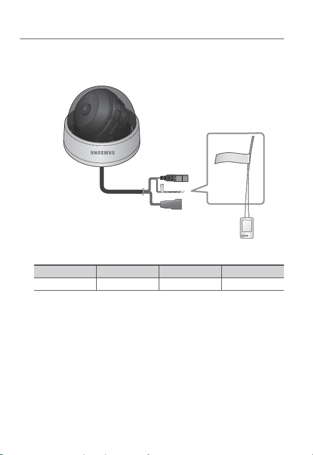
CONNECTING WITH OTHER DEVICE
Monitor Out
The BNC Out terminal of the product is provided for easier installation, and is not recommended
J
for monitoring purposes.
If you keep the BNC cable connected, a risk of lightening may cause damage or malfunction to
the product.
18_ installation & connection
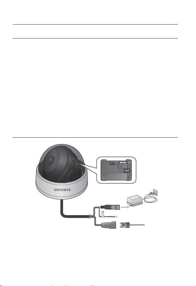
Power
Ethernet
Ethernet Connection
Connect the Ethernet cable to the local network or to the Internet.
Power Supply
Use the screwdriver to connect each line (+, –) of the power cable to the corresponding
power port of the camera.
Be careful not to reverse the polarity when you connect the power cable.
J
You can also use a router featuring PoE (Power over Ethernet) to supply power to the camera.
If both PoE and DC 12V are supplied, the product will operate with the first-applied power source.
Please make sure the monitor and camera are turned off when connecting them.
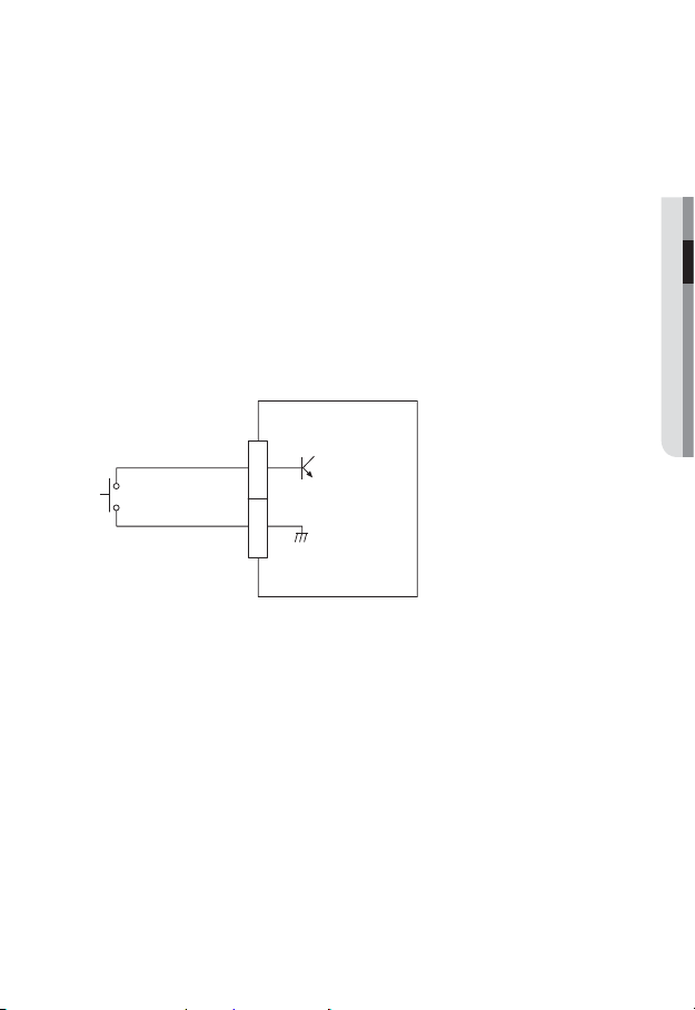
Alarm input Wiring Diagram
● INSTALLATION & CONNECTION
ALARM IN
GND
1
2
(5mA sink)
English _19
installation & connection
To connect to the alarm input port
Connect the alarm input signal to the cable input port.
=
A
N
l
a
r
W
m
O
I
N
R
B
=
G
N
K
D
C
A
L
B
SENSOR
Port Description Port Description
ARM-IN
To connect the alarm input signal
Connect one strand of each signal line (2-strand) of the sensors to the [ARM-IN] port, and
connect the other strand to the [GND] port.
Alarm Input Sensor Port
GND
Earth-grounding Port
20_ installation & connection
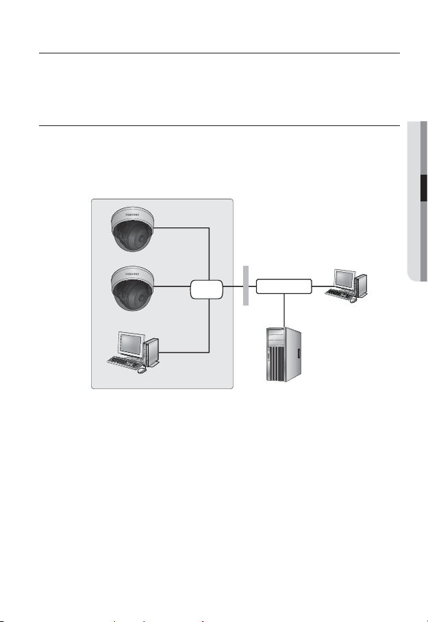
network connection and setup
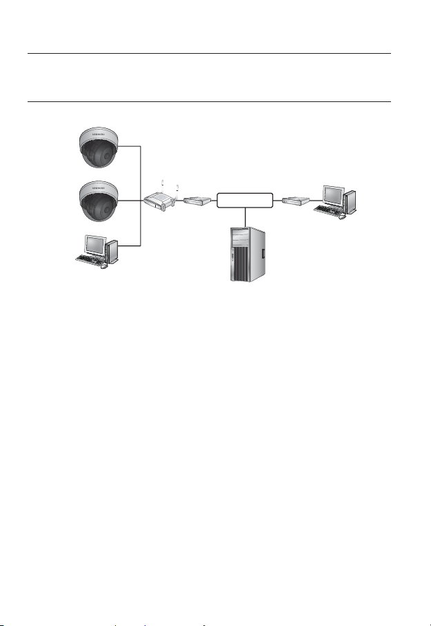
You can set up the network settings according to your network configurations.
CONNECTING THE CAMERA DIRECTLY TO LOCAL AREA
NETWORKING
Connecting to the camera from a local PC in the LAN
1. Launch an Internet browser on the local PC.
2. Enter the IP address of the camera in the address bar of the browser.
Camera
●
NETWORK CONNECTION AND SETUP
Firewall
INTERNET
External Remote PC
DDNS Server
(Data Center, KOREA)
26)
Switch
Camera
Local PC
<Local Network>
A remote PC in an external Internet out of the LAN network may not be able to connect to the
M
camera installed in the intranet if the port-forwarding is not properly set or a firewall is set.
In this case, to resolve the problem, contact your network administrator.
By factory default, the IP address will be assigned from the DHCP server automatically. If there is
no DHCP server available, the IP address will be set to 192.168.1.100.
To change the IP address, use the IP Installer.
For further details on IP Installer use, refer to “Static IP Setup”. (Page
English _21
network connection and setup
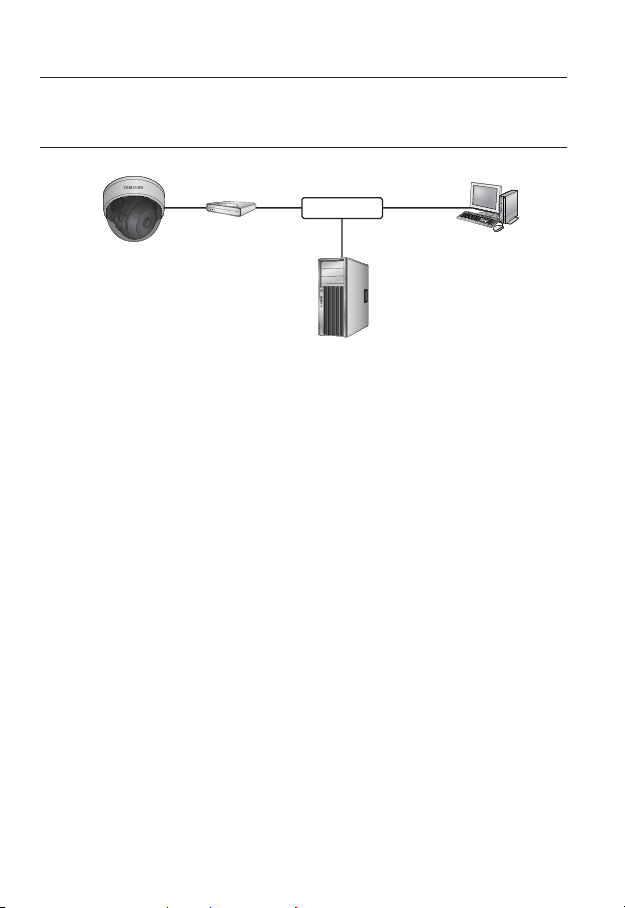
CONNECTING THE CAMERA DIRECTLY TO A DHCP
BASED DSL/CABLE MODEM
DSL/Cable
Camera
1. Use the cross LAN cable to connect the network cable directly to your PC.
2. Run the IP Installer and change the IP address of the camera so that you can use
the web browser on your desktop to connect to the Internet.
3. Use the Internet browser to connect to the camera.
4. Move to [Setup] page.
5. Move to [Network] – [DDNS] and configure the DDNS settings.
6. Move to [Network] – [Interface], and set the network type to [DHCP].
7. Connect the camera, which was removed from your PC, directly to the modem.
8. Restart the camera.
For registering the DDNS settings, refer to “Registering with DDNS”. (page 54)
M
For configuring the DDNS settings, refer to “DDNS”. (page 53)
For setting the network type, refer to “Interface”. (page 52)
Modem
INTERNET
DDNS Server
(Data Center, KOREA)
External Remote PC
22_ network connection and setup
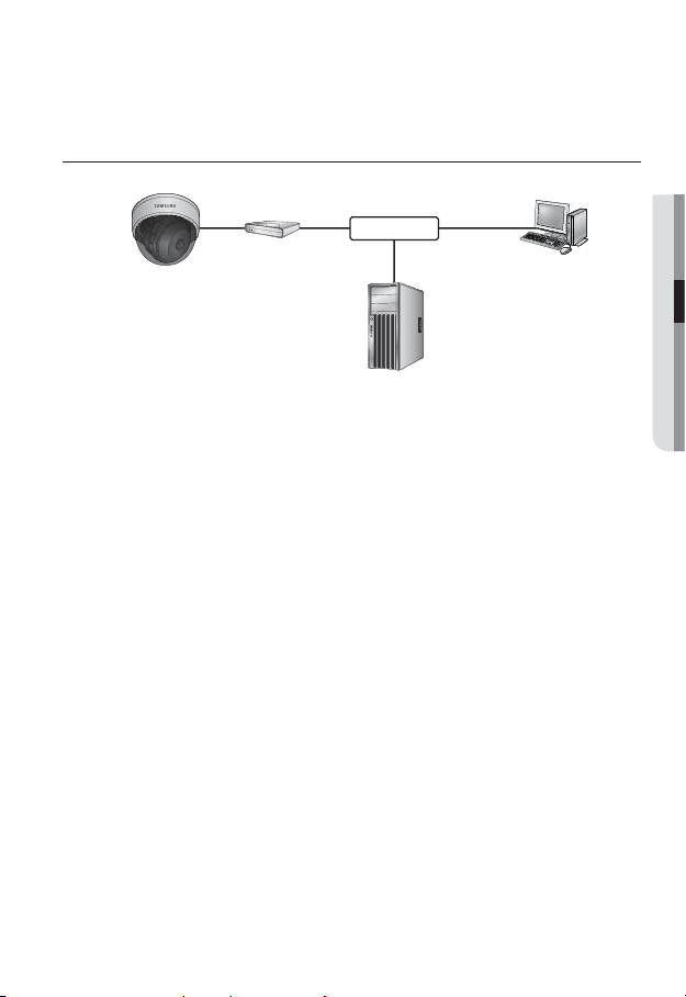
CONNECTING THE CAMERA DIRECTLY TO A PPPoE
MODEM
PPPoE Modem
Camera
1. Use the cross LAN cable to connect the network cable directly to your PC.
2. Run the IP Installer and change the IP address of the camera so that you can use
the web browser on your desktop to connect to the Internet.
3. Use the Internet browser to connect to the camera.
4. Move to [Setup] page.
5. Move to [Network] – [DDNS] and configure the DDNS settings.
6. Move to [Network] – [Interface], and set the network type to [PPPoE].
7. Connect the camera, which was removed from your PC, directly to the modem.
8. Restart the camera.
For registering the DDNS settings, refer to “Registering with DDNS”. (page 54)
M
For configuring the DDNS settings, refer to “DDNS”. (page 53)
For setting the network type, refer to “Interface”. (page 52)
INTERNET
DDNS Server
(Data Center, KOREA)
External Remote PC
●
NETWORK CONNECTION AND SETUP
English _23
network connection and setup
CONNECTING THE CAMERA TO A BROADBAND ROUTER
WITH THE PPPoE/CABLE MODEM
This is for a small network environment such as homes, SOHO and ordinary shops.
Camera
INTERNET
PPPoE or
Cable Modem
DDNS Server
(Data Center, KOREA)
External Remote
PC
Camera
Local PC
Broadband
Router
PPPoE or
Cable Modem
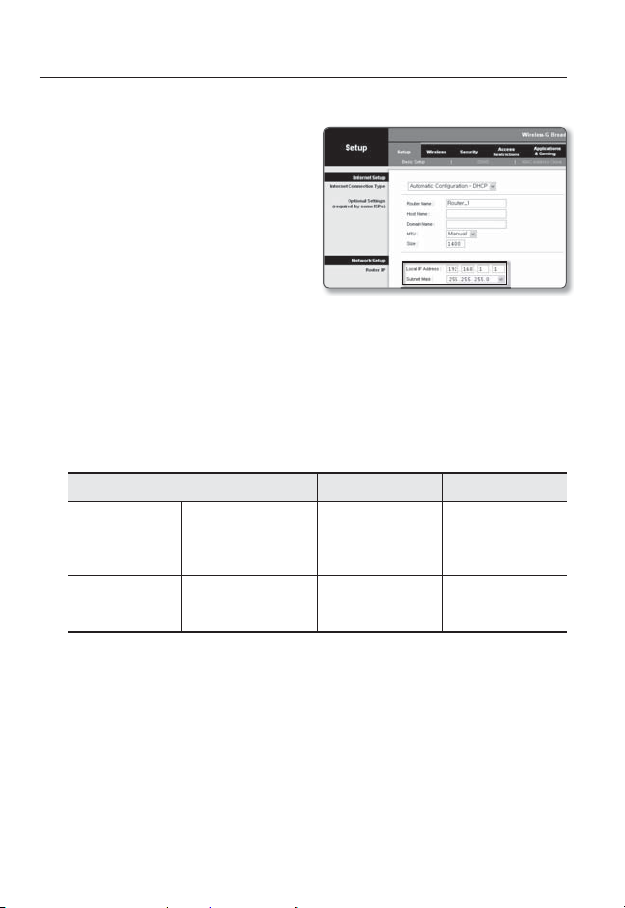
Configuring the network settings of the local PC connected to a
Broadband Router
Configuring the network settings of the local PC connected to a Broadband Router, follow
the instructions below.
• Select : <Network Neighborhood> <Properties> <Local Area Connection>
<Properties> <General> <Internet Protocol (TCP/IP)> <Properties>
<Obtain an IP address automatically> or <Use the following IP address>.
• Follow the instructions below if you select <Use the following IP address>:
ex1) If the address (LAN IP) of the Broadband Router is 192.168.1.1
IP address : 192.168.1.100
Subnet Mask : 255.255.255.0
Default Gateway : 192.168.1.1
ex2) If the address (LAN IP) of the Broadband Router is 192.168.0.1
IP address : 192.168.0.100
Subnet Mask : 255.255.255.0
Default Gateway : 192.168.0.1
ex3) If the address (LAN IP) of the Broadband Router is 192.168.xxx.1
IP address : 192.168.xxx.100
Subnet Mask : 255.255.255.0
Default Gateway : 192.168.xxx.1
For the address of the Broadband Router, refer to the product’s documentation.
M
Refer to the “Port Range Forward (Port Mapping) Setup” section of the Broadband Router’s
documentation. (Page
31)
24_ network connection and setup
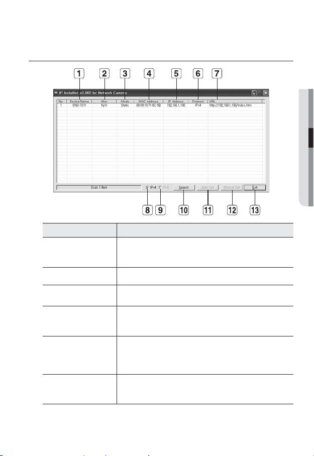
BUTTONS USED IN IP INSTALLER
Item Description
Device Name
Alias This function is not currently implemented.
b
Mode
c
MAC(Ethernet)
Address
IP Address
Protocol
Model name of the connected camera.
Click the column to sort the list by model name.
However, search will be stopped if clicked during the search.
Displays either <Static> or <Dynamic> for the current network connection
status.
Ethernet address for the connected camera.
Click the column to sort the list by Ethernet address.
However, search will be stopped if clicked during the search.
IP address.
Click the column to sort the list by IP address.
However, search will be stopped if clicked during the search.
The factory default is “192.168.1.100”.
Network setting for the camera.
The factory default is “IPv4”.
Cameras with the IPv6 setting will be displayed “IPv6”.
●
NETWORK CONNECTION AND SETUP
English _25

network connection and setup
Item Description
URL
IPv4 Scans for cameras with the IPv4 setting.
IPv6
Search
Auto Set The IP Installer automatically configures the network settings.
Manual Set You should configure the network settings manually.
Exit Exits the IP Installer program.
m
For the IP installer, use only the installer version provided in the installation CD or use the
M
latest one if available. You can download the latest version from the Samsung web site (www.
samsungipolis.com).
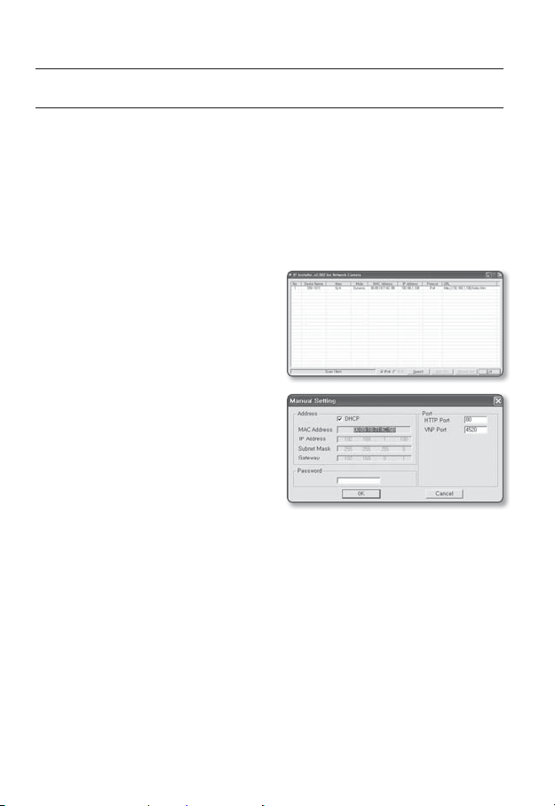
STATIC IP SETUP
Manual Network Setup
Run <IP Installer_vX.XX.exe> to display the camera search list.
At the initial startup, both [Auto Set] and [Manual Set] will be grayed out.
For cameras found with the IPv6 setting, these buttons will be grayed out as the cameras do not
M
support this function.
1. Select a camera in the search list.
Find the MAC (Ethernet) address
labeled on the rear of the camera.
Both the [Auto Set] and [Manual Set]
buttons will be activated.
2. Click [Manual Set].
The Manual Setting dialog appears.
The default values of <IP Address>,
<Subnet Mask>, <Gateway>, <HTTP Port> and <VNP Port> of the camera will
be displayed.
DDNS URL address enabling access from the external Internet.
However, this will be replaced with the <IP Address> of the camera if
DDNS registration has failed.
Scans for cameras with the IPv6 setting.
Activated in an IPv6 compliant environment.
Scans for cameras that are currently connected to the network.
However, this button will be grayed out if neither IPv4 nor IPv6 is checked.
26_ network connection and setup
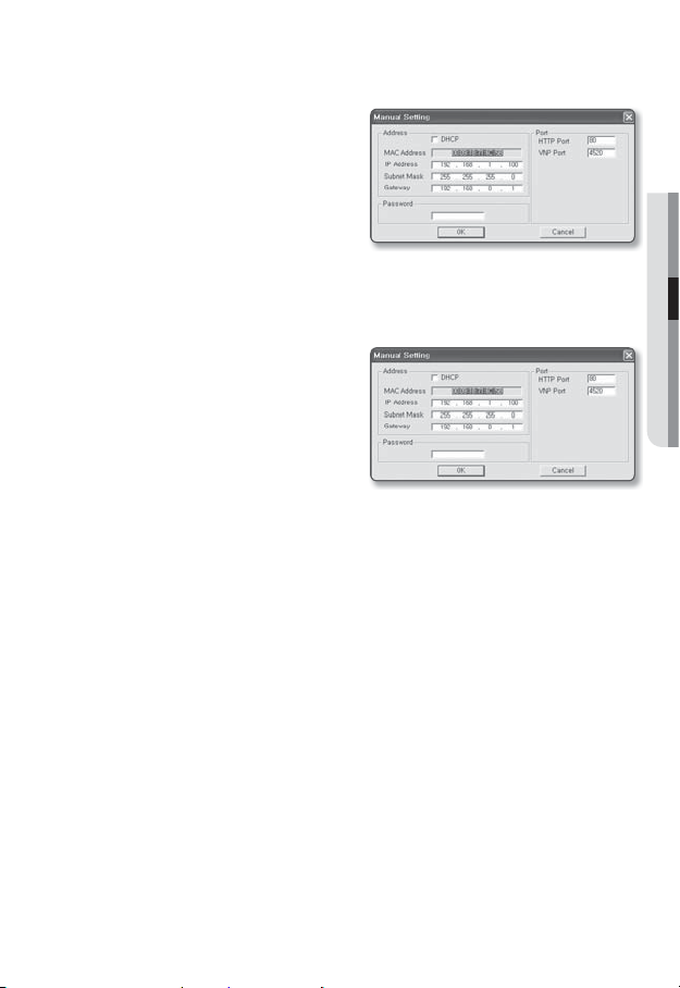
3. In the <Address> pane, provide the
necessary information.
• MAC (Ethernet) Address : The MAC
(Ethernet) address of the applicable
camera will be set automatically so
you don't need to input it manually.
You can configure the static IP settings
M
only if the DHCP checkbox is unchecked.
If not using a Broadband Router
For setting <IP Address>, <Subnet Mask>, and <Gateway>, contact your network administrator.
4. In the <Port> pane, provide
necessary information.
• HTTP Port : Used to access the
camera using the Internet browser,
defaulted to 80. Use the spin button
to change the HTTP Port value.
• VNP Port : Used to control the video
signal transfer, defaulted to 4520.
5. Enter the password.
This is the login password for the “admin” user who accesses the camera.
The default password is “4321”.
The default password can be exposed to a hacking thread so it is recommended to change the
J
password after installing the product.
Note that the security and other related issues caused by the unchanged password shall be
responsible for the user.
6. Click [OK].
Manual network setup will be completed.
●
NETWORK CONNECTION AND SETUP
English _27
network connection and setup
If using a Broadband Router
• IP Address : Enter an address falling in
the IP range provided by the Broadband
Router.
ex) 192.168.1.2~254,
192.168.0.2~254,
192.168.XXX.2~254
• Subnet Mask : The <Subnet Mask>
of the Broadband Router will be the
<Subnet Mask> of the camera.
• Gateway : The <Local IP Address> of
the Broadband Router will be the <Gateway> of the camera.
The settings may differ depending on the connected Broadband Router model.
M
For more information, refer to the user manual of the applicable router.
Refer to the “Port Range Forward (Port Mapping) Setup” section of the Broadband Router’s
documentation. (Page
If the Broadband Router has more than one camera connected
Configure the IP related settings and the Port related settings distinctly with each other.
31)
Category Camera #1 Camera #2
IP related settings
Port related settings
If the <HTTP Port> is set other than 80, you must provide the <Port> number in the address bar
M
of the Internet browser before you can access the camera.
ex) http://IP address : HTTP Port
28_ network connection and setup
IP Address
Subnet Mask
Gateway
HTTP Port
VNP Port
http://192.168.1.100:8080
192.168.1.100
255.255.255.0
192.168.1.1
8080
4520
192.168.1.101
255.255.255.0
192.168.1.1
8081
4521
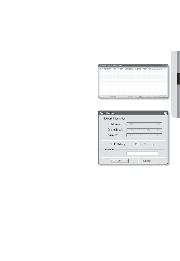
Auto Network Setup
Run <IP Installer_vX.XX.exe> to display the camera search list.
At the initial startup, both [Auto Set] and [Manual Set] will be grayed out.
For cameras found with the IPv6 setting, these buttons will be grayed out as the cameras do not
M
support this function.
1. Select a camera in the search list.
Find the MAC (Ethernet) address
labeled on the rear of the camera.
Both the [Auto Set] and [Manual Set]
buttons will be activated.
2. Click [Auto Set].
The Auto Setting dialog appears.
The <IP Address>, <Subnet Mask>,
and <Gateway> will be set automatically.
3. Enter the password.
This is the login password for the
“admin” user who accesses the
camera. The default password is
“4321”.
The default password can be exposed to
a hacking thread so it is recommended to
change the password after installing the
product.
Note that the security and other related issues
caused by the unchanged password shall be
responsible for the user.
4. Click [OK].
Auto network setup will be completed.
●
NETWORK CONNECTION AND SETUP
English _29
network connection and setup
DYNAMIC IP SETUP
Dynamic IP Environment Setup
• Example of the Dynamic IP environment
- If a Broadband Router, with cameras connected, is assigned an IP address by the
DHCP server
- If connecting the camera directly to modem using the DHCP protocols
- If IPs are assigned by the internal DHCP server via the LAN
Checking the Dynamic IP
1. Run the IP Installer on the user’s local
machine to display cameras allocated
with <Dynamic IP> addresses in the
list.
2. Select a camera in the list, and click
[Manual Set] to check the <Dynamic
IP> of the camera.
If you uncheck <DHCP>, you can
change IP to <Static>.
30_ network connection and setup
 Loading...