

Samsung CLP-770ND Service Manual
Service Manual
■ Speed : 32 / 32 ppm (A4)
■ Resolution : up to 9600 X 600 dpi effective output.
■ 7K/7K Black/Color toner
(Initial : 3.5K/3.5K)
■ Machine Life : 300K or 5 Years
■ Paper handling
: Maximum 1,600 Sheets Paper Capacity
: 500sh cassette, 500sh SCF x 2 EA
: 100 MP
The keynote of Product
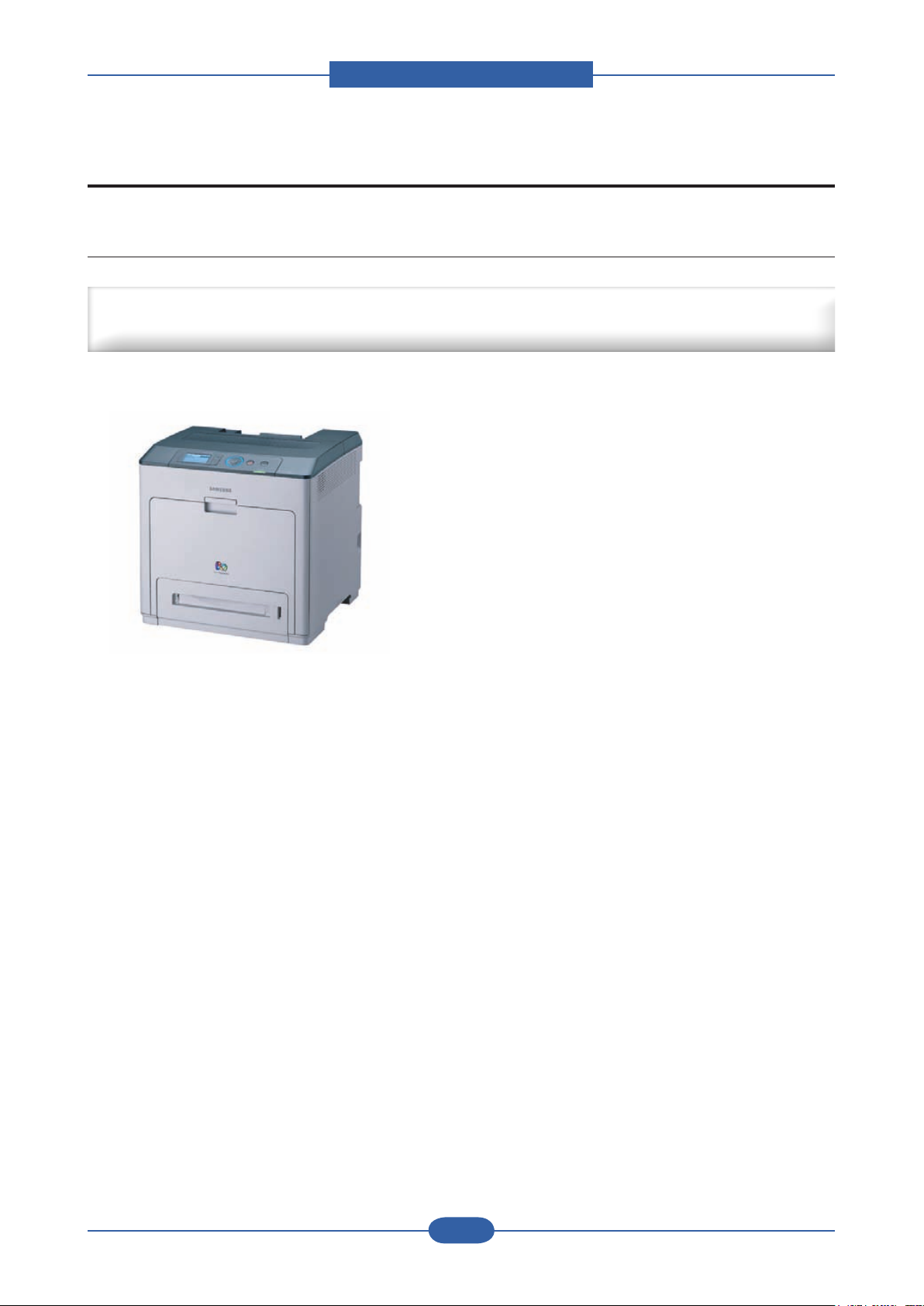
Color Laser Printer
CLP-770ND
■ 80 GB HDD (Option)
■ Memory : 256 MB (Max. 768 MB)
■ Duplex printing
■ N/W, USB 2.0, EDI, Wireless option
■ 4 Line LCD

GSPN (Global Service Partner Network)
North America : service.samsungportal.com
Latin America : latin.samsungportal.com
CIS : cis.samsungportal.com
Europe : europe.samsungportal.com
China : china.samsungportal.com
Asia : asia.samsungportal.com
Mideast & Africa : mea.samsungportal.com
ⓒ
Samsung Electronics Co.,Ltd. March. 2009
Printed in Korea.
VERSION NO. : 1.00 CODE : 0770-00000E

chapter 1 Precautions
1.1 Safety Warning …………………………………………………… 1-1
1.2 Caution for safety ………………………………………………… 1-2
1.3 ESD Precautions ………………………………………………… 1-5
chapter 2 Product Overview
2.1 Product Summary ………………………………………………… 2-1
2.2 Sepcications …………………………………………………… 2-2
2.2.1 General Print Engine ……………………………………… 2-2
2.2.2 Controller & S/W …………………………………………… 2-3
2.2.3 Paper Handling ……………………………………………… 2-4
2.2.4 Reliability & Service ………………………………………… 2-5
2.2.5 Environment ………………………………………………… 2-6
2.2.6 Packing & Accessory ……………………………………… 2-6
2.2.7 Consumables ………………………………………………… 2-7
2.2.8 Option ……………………………………………………… 2-8
2.3 Model Comparison Table ………………………………………… 2-9
2.4 Product Conguration …………………………………………… 2-11
Contents
2.4.1 Main PBA …………………………………………………… 2-15
2.4.2 SMPS Board ………………………………………………… 2-19
2.4.3 HVPS Board ………………………………………………… 2-21
2.4.4 HVPS_Sub Board ………………………………………… 2-23
2.4.5 Fuser Drive Board ………………………………………… 2-24
2.4.6 OPE Board ………………………………………………… 2-25
2.4.7 Feeding Section …………………………………………… 2-26
2.4.8 LSU ( Laser scanning unit ) ………………………………… 2-27
2.4.9 Fuser Unit …………………………………………………… 2-28
2.4.10 PTB(Paper Transfer Belt) Unit …………………………… 2-29
2.4.11 Motors ……………………………………………………… 2-29
2.4.12 Sensors …………………………………………………… 2-30

chapter 3 Maintenance and Disassembly
3.1 Precautions when replacing parts ……………………………… 3-1
3.1.1 Precautions when assembling and disassembling ……… 3-1
3.1.2 Preautions when handling PBA …………………………… 3-1
3.1.3 Releasing Plastic Latches ………………………………… 3-1
3.2 Replacing a Maintenance Parts ……………………………… 3-2
3.2.1 Fuser Unit …………………………………………………… 3-2
3.2.2 Pick up roller ………………………………………………… 3-2
3.3 General Disassembly …………………………………………… 3-3
3.3.1 Cover Unit …………………………………………………… 3-3
3.3.2 Front Cover Unit …………………………………………… 3-6
3.3.3 OPE Unit……………………………………………………… 3-7
3.3.4 HVPS Board ………………………………………………… 3-8
3.3.5 Main PBA …………………………………………………… 3-9
3.3.6 SMPS Board ………………………………………………… 3-9
3.3.7 Fuser Control Board ………………………………………… 3-10
3.3.8 HVPS sub board(AC Board) ……………………………… 3-10
3.3.9 LSU Unit ……………………………………………………… 3-11
3.3.10 SOLENOID and CLUTCH-FEED ………………………… 3-12
Contents
chapter 4 Alignment & Troubleshooting
4.1 Alignment and Adjustments ……………………………………… 4-1
4.1.1 Control Panel ………………………………………………… 4-1
4.1.2 Understanding The Status LED …………………………… 4-2
4.1.3 Menu Overview ……………………………………………… 4-3
4.1.4 Tech Mode …………………………………………………… 4-7
4.1.5 Firmware Upgrade ………………………………………… 4-13
4.2 Troubleshooting…………………………………………………… 4-19
4.2.1 Procedure of Checking the Symptoms …………………… 4-19
4.2.2 Display Meassage Troubleshooting ……………………… 4-20
4.2.3 Feeding Problems and solutions ………………………… 4-29
4.2.4 Image Quality Problems and solutions …………………… 4-36
4.2.5 Common Problems and solutions ………………………… 4-42
4.2.6 Network problems and soltutions ………………………… 4-43

chapter 5 System Diagram
5.1 Main PBA (SPGPXm) Block Diagram ………………………… 5-1
5.2 OPE PANEL Block Diagram …………………………………… 5-2
5.3 Connection Diagram……………………………………………… 5-3
chapter 6 Reference Information
6.1 Tools for Troubleshooting ……………………………………… 6-1
6.2 Acronyms and Abbreviations …………………………………… 6-2
6.3 Select a location for the printer ………………………………… 6-4
6.4 A4 ISO 19752 Standard Pattern ………………………………… 6-5
Contents
attached Parts Catalog
Power Cord ………………………………………………………… 2
Harness Connection Table ………………………………………… 3
Used Screw List …………………………………………………… 5
Maintenance parts and Option unit ……………………………… 7
Thumbnail …………………………………………………………… 8
1. MAIN ……………………………………………………………… 9
2. COVER …………………………………………………………… 11
3. TOP COVER …………………………………………………… 13
4. FRONT COVER ………………………………………………… 15
5. FRAME …………………………………………………………… 17
6. FUSER_BLDC_MAIN ………………………………………… 19
7. FRAME_BOTTOM_MAIN ……………………………………… 21
8. FRAME LEFT ASS’Y …………………………………………… 23
9. FRAME RIGHT ASS’Y ………………………………………… 25
10. FEED DRIVE …………………………………………………… 27
11. FUSER ………………………………………………………… 29
12. CASSETTE …………………………………………………… 32
13. SCF ……………………………………………………………… 34
14. CASSETTE-SCF ……………………………………………… 36
Precautions
1. Precautions
In order to prevent accidents and to prevent damage to the equipment please read the precautions listed
below carefully before servicing the printer and follow them closely.
1.1 Safety Warning
(1) Only to be serviced by appropriately qualied service engineers.
High voltages and lasers inside this product are dangerous. This printer should only be serviced by a
suitably trained and qualied service engineer.
(2) Use only Samsung replacement parts
There are no user serviceable parts inside the printer. Do not make any unauthorized changes or
additions to the printer, these could cause the printer to malfunction and create electric shock or re haz-
ards.
(3) Laser Safety Statement
The Printer is certied in the U.S. to conform to the requirements of DHHS 21 CFR, chapter 1 Subchapter
J for Class 1(1) laser products, and elsewhere, it is certied as a Class I laser product con-forming to the
requirements of IEC 825. Class I laser products are not considered to be hazardous. The laser system
and printer are designed so there is never any human access to laser radiation above a Class I level
during normal operation, user maintenance, or prescribed service condition.
Warning >> Never operate or service the printer with the protective cover removed from Laser/
Scanner assembly. The reected beam, although invisible, can damage your eyes.
When using this product, these basic safety pre-cautions should always be followed to
reduce risk of re, electric shock, and injury to persons.
Service Manual
1-1
Samsung Electronics

Precautions
Service Manual
1-2
Samsung Electronics
1.2 Caution for safety
1.2.1 Toxic material
This product contains toxic materials that could cause illness if ingested.
(1) If the LCD control panel is damaged it is possible for the liquid inside to leak. This liquid is toxic. Contact
with the skin should be avoided, wash any splashes from eyes or skin immediately and contact your
doctor. If the liquid gets into the mouth or is swallowed see a doctor immediately.
(2) Please keep Drum cartridge and Toner Cartridge away from children. The toner powder contained in the
Drum cartridge and Toner Cartridge may be harmful and if swallowed you should contact a doctor.
1.2.2 Electric Shock and Fire Safety Precautions
Failure to follow the following instructions could cause electric shock or potentially cause a re.
(1) Use only the correct voltage, failure to do so could damage the printer and potentially cause a re or
electric shock.
(2) Use only the power cable supplied with the printer. Use of an incorrectly specied cable could cause the
cable to overheat and potentially cause a re.
(3) Do not overload the power socket, this could lead to overheating of the cables inside the wall and could
lead to a re.
(4) Do not allow water or other liquids to spill into the printer, this can cause electric shock. Do not allow
paper clips, pins or other foreign objects to fall into the printer these could cause a short circuit leading to
an electric shock or re hazard.
(5) Never touch the plugs on either end of the power cable with wet hands, this can cause electric shock.
When servicing the printer remove the power plug from the wall socket.
(6) Use caution when inserting or removing the power connector. The power connector must be inserted
completely otherwise a poor contact could cause overheating possibly leading to a re. When removing
the power connector grip it rmly and pull.
(7) Take care of the power cable. Do not allow it to become twisted, bent sharply round corners or other
wise damaged. Do not place objects on top of the power cable. If the power cable is damaged it could
overheat and cause a re or exposed cables could cause an electric shock. Replace a damaged power
cable immediately, do not reuse or repair the damaged cable. Some chemicals can attack the coating on
the power cable, weakening the cover or exposing cables causing re and shock risks.
(8) Ensure that the power sockets and plugs are not cracked or broken in any way. Any such defects should
be repaired immediately. Take care not to cut or damage the power cable or plugs when moving the
machine.
(9) Use caution during thunder or lightening storms. Samsung recommend that this machine be disconnected
from the power source when such weather conditions are expected. Do not touch the machine or the
power cord if it is still connected to the wall socket in these weather conditions.
(10) Avoid damp or dusty areas, install the printer in a clean well ventilated location. Do not position the
machine near a humidier. Damp and dust build up inside the machine can lead to overheating and
cause a re.
(11) Do not position the printer in direct sunlight. This will cause the temperature inside the printer to rise
possibly leading to the printer failing to work properly and in extreme conditions could lead to a re.
(12) Do not insert any metal objects into the machine through the ventilator fan or other part of the casing, it
could make contact with a high voltage conductor inside the machine and cause an electric shock.

Precautions
Service Manual
1-3
Samsung Electronics
1.2.3 Handling Precautions
The following instructions are for your own personal safety, to avoid injury and so as not to damage the
printer
(1) Ensure the printer is installed on a level surface, capable of supporting its weight. Failure to do so could
cause the printer to tip or fall.
(2) The printer contains many rollers, gears and fans. Take great care to ensure that you do not catch your
ngers, hair or clothing in any of these rotating devices.
(3) Do not place any small metal objects, containers of water, chemicals or other liquids close to the printer
which if spilled could get into the machine and cause damage or a shock or re hazard.
(4) Do not install the machine in areas with high dust or moisture levels, beside on open window or close to a
humidier or heater. Damage could be caused to the printer in such areas.
(5) Do not place candles, burning cigarettes, etc on the printer, These could cause a re.
1.2.4 Assembly / Disassembly Precautions
Replace parts carefully, always use Samsung parts. Take care to note the exact location of parts and also
cable routing before dismantling any part of the machine. Ensure all parts and cables are replaced correctly.
Please carry out the following procedures before dismantling the printer or replacing any parts.
(1) Check the contents of the machine memory and make a note of any user settings. These will be erased if
the mainboard or network card is replaced.
(2) Ensure that power is disconnected before servicing or replacing any electrical parts.
(3) Disconnect printer interface cables and power cables.
(4) Only use approved spare parts. Ensure that part number, product name, any voltage, current or
temperature rating are correct.
(5) When removing or re-tting any parts do not use excessive force, especially when tting screws into
plastic.
(6) Take care not to drop any small parts into the machine.
(7) Handling of the OPC Drum
- The OPC Drum can be irreparably damaged if it exposed to light.
Take care not to expose the OPC Drum either to direct sunlight or to uorescent or incandescent
room lighting. Exposure for as little as 5 mins can damage the surface? photoconductive properties
and will result in print quality degradation. Take extra care when servicing the printer. Remove the
OPC Drum and store it in a black bag or other lightproof container. Take care when working with the
covers(especially the top cover) open as light is admitted to the OPC area and can damage the OPC
Drum.
- Take care not to scratch the green surface of OPC Drum Unit.
If the green surface of the Drum Cartridge is scratched or touched the print quality will be compromised.

Precautions
Service Manual
1-4
Samsung Electronics
1.2.5 Disregarding this warning may cause bodily injury
(1) Be careful with the high temperature part.
The fuser unit works at a high temperature. Use caution when working on the printer. Wait for the fuser to
cool down before disassembly.
(2) Do not put nger or hair into the rotating parts.
When operating a printer, do not put hand or hair into the rotating parts (Paper feeding entrance, motor,
fan, etc.). If do, you can get harm.
(3) When you move the printer
- The equipment weighs approximately 30 Kg (including consumables), therefore pay attention when
handling it.
- Be sure not to hold the movable parts or units (e.g. the control panel, DADF) when transporting the
equipment.
- Be sure to use a dedicated outlet with 110V/220Vpower input.
- The equipment must be grounded for safety.
- Select a suitable place for installation. Avoid excessive heat, high humidity, dust, vibration and direct
sunlight.
- Provide proper ventilation since the equipment emits a slight amount of ozone.
- The equipment shall be installed near the socket outlet and shall be accessible.
- Be sure to x and plug in the power cable securely after the installation so that no one trips over it.

Precautions
Service Manual
1-5
Samsung Electronics
1.3 ESD Precautions
Certain semiconductor devices can be easily damaged by static electricity. Such components are commonly
called “Electrostatically Sensitive (ES) Devices” or ESDs. Examples of typical ESDs are: integrated circuits,
some eld effect transistors, and semiconductor “chip” components.
The techniques outlined below should be followed to help reduce the incidence of component damage
caused by static electricity.
Caution >>Be sure no power is applied to the chassis or circuit, and observe all other safety precautions.
1. Immediately before handling a semiconductor component or semiconductor-equipped assembly, drain
off any electrostatic charge on your body by touching a known earth ground. Alternatively, employ a
commercially available wrist strap device, which should be removed for your personal safety reasons prior
to applying power to the unit under test.
2. After removing an electrical assembly equipped with ESDs, place the assembly on a conductive surface,
such as aluminum or copper foil, or conductive foam, to prevent electrostatic charge buildup in the vicinity
of the assembly.
3. Use only a grounded tip soldering iron to solder or desolder ESDs.
4. Use only an “anti-static” solder removal device. Some solder removal devices not classied as “anti-static”
can generate electrical charges sufcient to damage ESDs.
5. Do not use Freon-propelled chemicals. When sprayed, these can generate electrical charges sufcient to
damage ESDs.
6. Do not remove a replacement ESD from its protective packaging until immediately before installing it. Most
replacement ESDs are packaged with all leads shorted together by conductive foam, aluminum foil, or a
comparable conductive material.
7. Immediately before removing the protective shorting material from the leads of a replacement ESD, touch
the protective material to the chassis or circuit assembly into which the device will be installed.
8. Maintain continuous electrical contact between the ESD and the assembly into which it will be installed,
until completely plugged or soldered into the circuit.
9. Minimize bodily motions when handling unpackaged replacement ESDs. Normal motions, such as
the brushing together of clothing fabric and lifting one’s foot from a carpeted oor, can generate static
electricity sufcient to damage an ESD.
Product spec and feature
2. Product spec and feature
2.1 Product Summary
High performance CLBP at a Low Cost of Printing
Large Workgroup (SMB/Corp) & Tender Biz
■ Speed : 32 / 32 ppm (A4)
■ Resolution : up to 9600 X 600 dpi effective output.
■ 7K/7K Black/Color toner (Initial : 3.5K/3.5K)
■ Machine Life : 300K or 5 Years
■ Paper handling
: Maximum 1,600 Sheets Paper Capacity
: 500sh cassette, 500sh SCF x 2 EA
: 100 MP
■ 80 GB HDD (Option)
■ Memory : 256 MB (Max. 768 MB)
■ Duplex printing
■ N/W, USB 2.0, EDI, Wireless option
■ 4 Line LCD
Service Manual
2-1
Samsung Electronics
Product spec and feature
Service Manual
2-2
Samsung Electronics
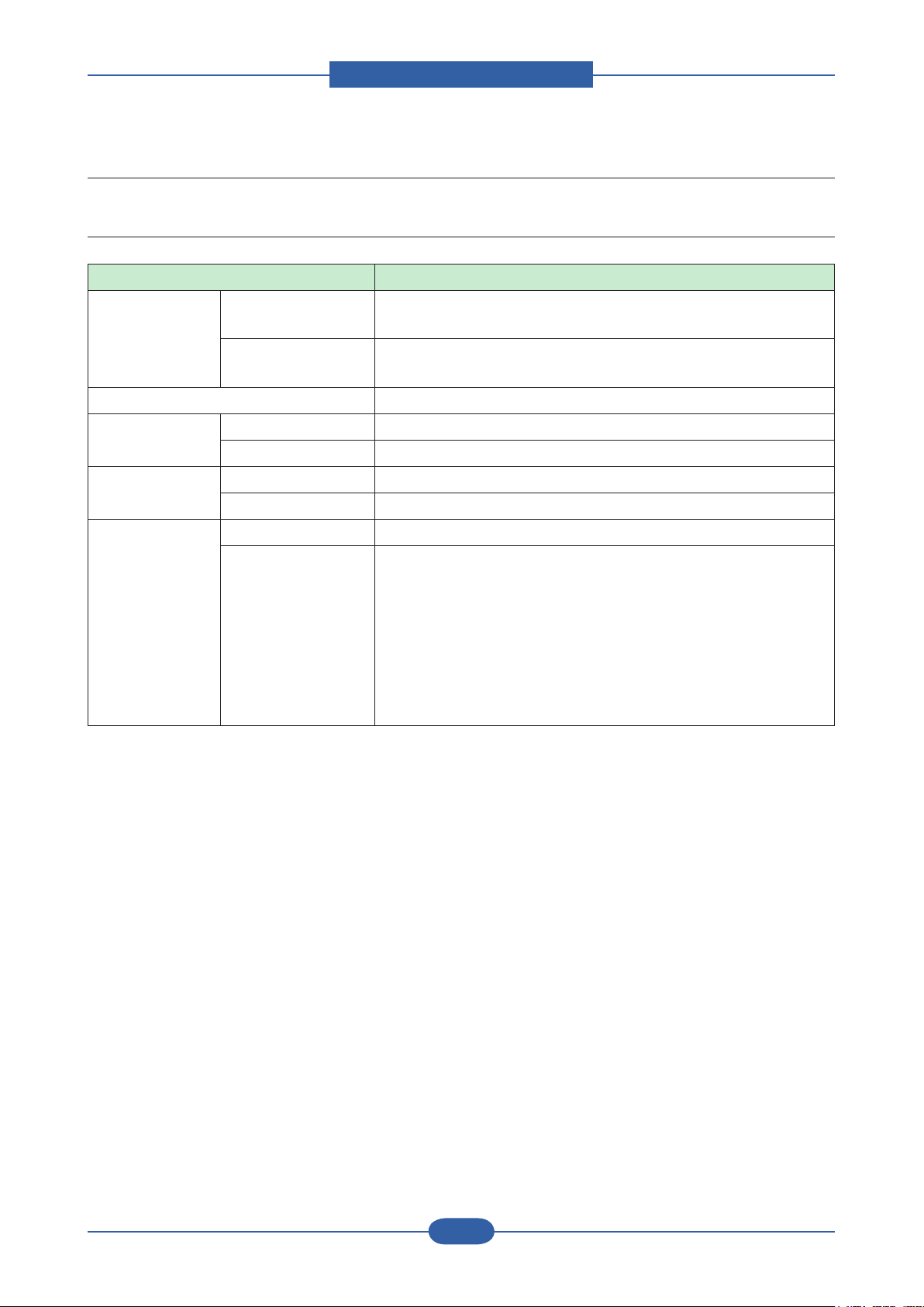
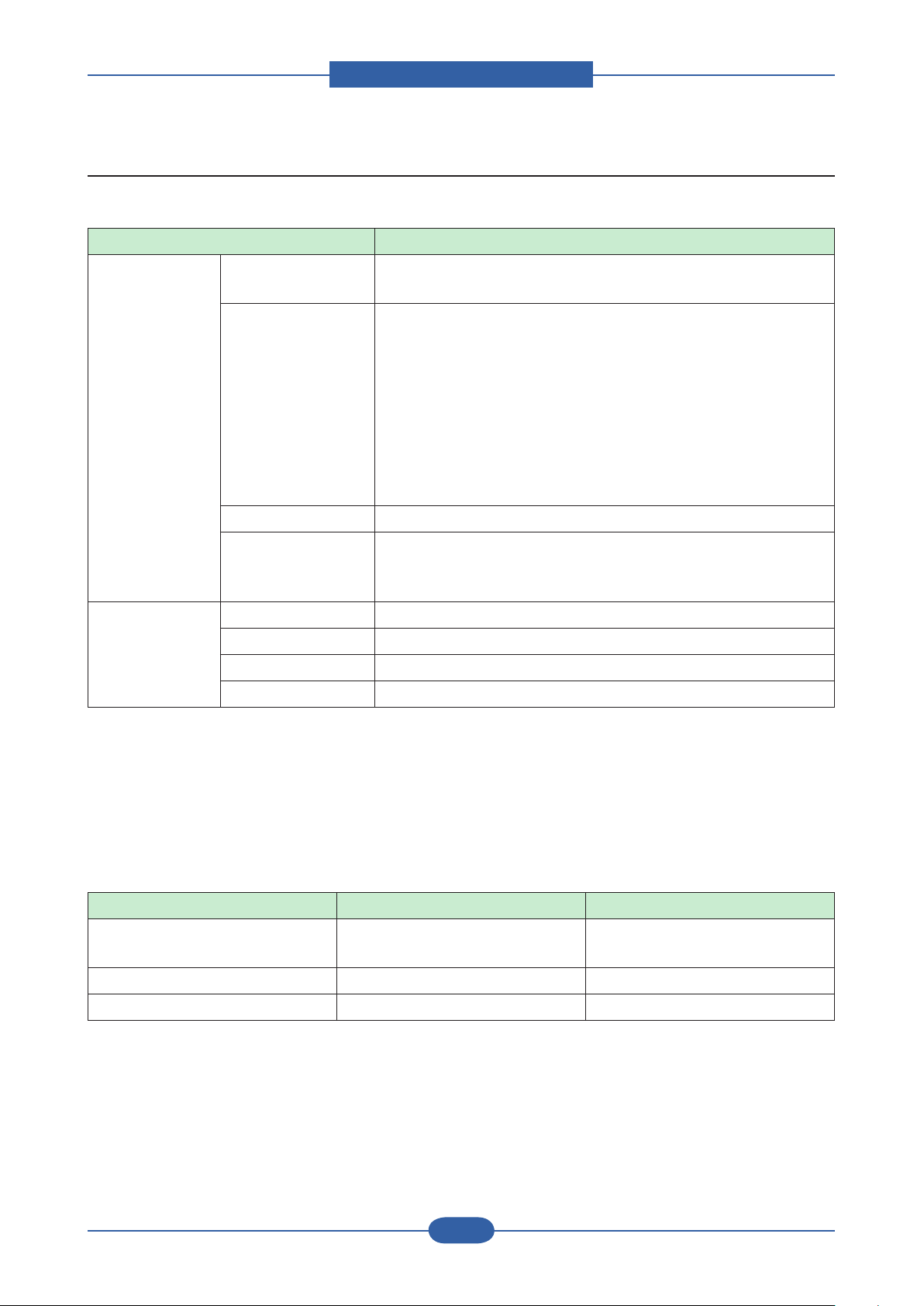
2.2 Sepcications
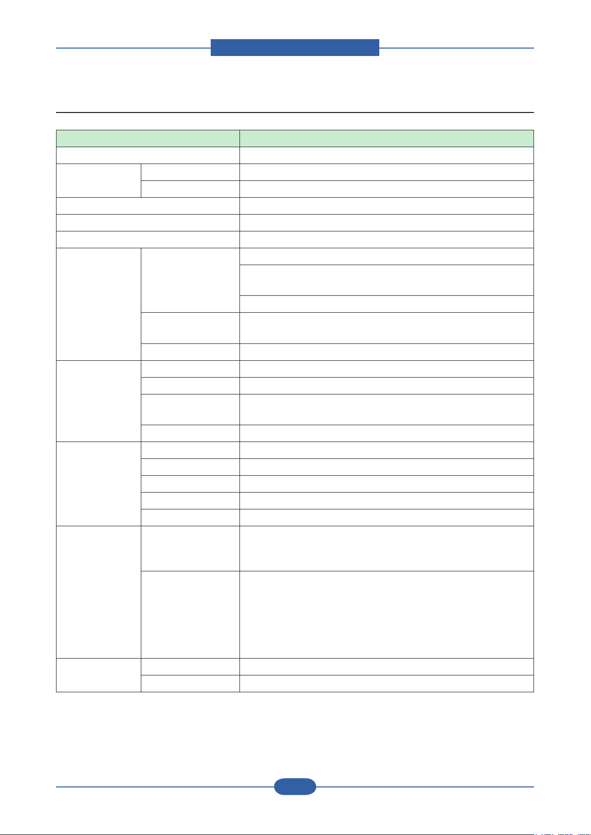
2.2.1 General Print Engine
Item Description
Engine Speed Simplex B&W : Up to 32 ppm in A4
Color : Up to 32 ppm in A4
Duplex B&W : Up to 16 ipm in A4
Color : Up to 16 ipm in A4
Warmup time Less than 25 sec
FPOT (B&W) From Ready Less than 10 sec
From Idle Less than 28 sec
FPOT (Color) From Ready Less than 11 sec
From Idle
Resolution Optical 600 x 600 dpi
Support ■ PCL 6
Less than 30 sec
Best : up to 9,600 x 600 effective output
Normal : up to 2,400 x 600 dpi
Draft : up to 600 x 600 dpi
■ PostScript 3
Best : up to 9,600 x 600 effective output
Normal : up to 1,200 x 600 dpi
Draft : up to 600x600 dpi
Product spec and feature
Service Manual
2-3
Samsung Electronics
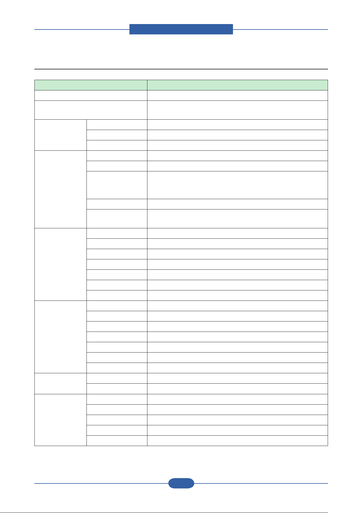
2.2.2 Controller & S/W
Item Description
MPU 800 MHz
Memory Std. 256 MB
Max. 768 MB
Memory Expansion 1 Slot
Printer Languages PostScript 3, PCL5c, PCL6
Fonts 93 scalable and 1 bitmap PCL and 136 PS
Driver Supporting OS Windows 2000/XP/2003/Vista/Server 2003/Window Server 2008
Various Linux including Red Hat 8.0~9.0, Mandrake 9.2~10.1,
SuSE 8.2~9.2 and Fedora Core 1~4
Mac OS 10.1 ~10.5 and Universal Mac
Default Driver
WHQL Windows 2000/XP/2003/Vista
Application Printer Setting Utility USB
Smart Panel Yes (USB / Network, Install Default)
Network
Management
SmarThru4 N/A
Interface Parallel N/A
USB USB 2.0
Network Ethernet 10/100 Base TX
Wireless LAN Option
EDI Yes
Network
Interface
Protocol TCP/IPv4/v6, SNMPv2/v3, HTTP(S), DHCP/BOOTP, DNS,
Network OS Windows 2000/XP(32/64bit)/2003/Server(32/64bit)/Vista
- PCL6
- including Mono Only Driver
Set IP, SyncThru Web Admin Service 4.0 (SWAS 4.0)
(Windows: IExplorer 5.5 or higher, Linux/Mac: not supported)
WINS, mDNS, SLP, UPnP, Standard TCP/IP Printing/IPP(S)/
SMTP/ LDAP
NetWare 5.x, 6.x
Mac OS 10.3~10.5 - TCP/IP Only
Various Linux OS including Red Hat 8.0~9.0, Fedora Core 1~4,
Mandrake 9.2~10.1, and SuSE 8.2~9.2
HP-UX, Solaris, SunOS, SCO UNIX
User Interface LCD & Button 4 Line LCD
LED 1 LED for status (Green/Red)
Product spec and feature
Service Manual
2-4
Samsung Electronics
2.2.3 Paper Handling
Item Description
Standard Capa. 500-sheet Cassette Tray, 100 MP
Max. Capa. 1600 sheets @ 80g/㎡ (500-sheet CST, 500-sheet SCFx2,
100MP)
Printing Max. Size 216 x 356mm (8.5” x 14”)
Min. Size 76 x 127 mm (3” x 5”)
Margin(T/B/L/R) 4 mm, 4 mm, 4 mm, 4 mm
Multi-purpose
tray
Standard
Cassette
Tray
Optional
Cassette Tray
Capacity 100 sheets @ 75g/
Media sizes A4 148.5x210 ~ Legal 216x356 (8.5”x14”)
Media type Printer Default, Plain Paper, Thick, Thin, Cotton, Archive Paper,
Bond, Card Stock, Labels, Preprinted, Color Paper, Envelope,
Recycled
Media weight 16~58lb (60 to 220g/㎡)
Sensing Empty sensing
No size sensor
Capacity 500 sheets @ 80g/
Media sizes 76 x 127 mm (3” x 5”) ~ 216 x 356mm (8.5” x 14”)
Media types Plain paper
Media weight 16~28lb (60 to 105g/㎡)
Size sensor Paper size sensor
User Interface Indicator
Sensing Paper empty sensor
Capacity 500 sheets @ 75g/
Media sizes A5 148.5 x210mm ~ Legal 216 x 356mm (8.5" x 14")
Media types Plain paper
㎡
㎡
㎡
Media weight 16~28lb (60 to 105g/㎡)
Size sensor Paper size sensor
User Interface Indicator
Sensing Empty sensing
Output Stacking Capacity 250 sheets @ 80g/
Output Full sensing Yes
Duplex Supporting Std.
Throughput N/A
Media sizes A4, Letter, Legal, Ocio, Folio
Media types Palin paper only
Media weight 16~32lb (60 to 120g/㎡)
㎡
Product spec and feature
Service Manual
2-5
Samsung Electronics
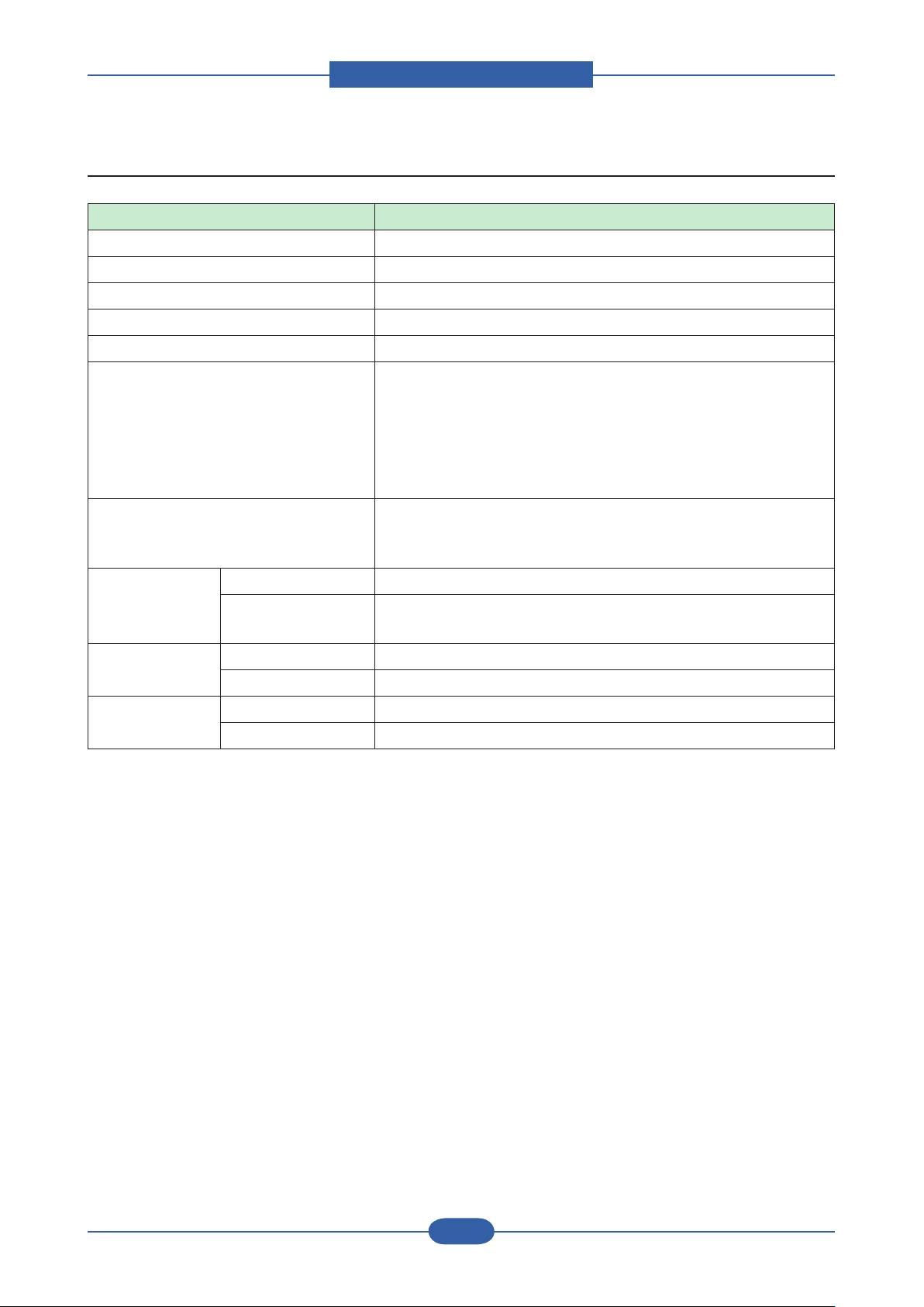
2.2.4 Reliability & Service
Item Description
Printing Volume(AMPV) 1433 page ( B&W : 573 page, Color : 860 pages)
Max Monthly Duty 120,000 pages
MPBF 100,000 pages
MTTR <30 min.
SET Life Cycle 300,000 image or 5 years whitchever comes rst
System-record Total page count (color/mono)
Fuser life
Transfer belt life
Toner Life(CMYK)
Tray pickup-Roller life
First operation date
Test Print Conguration Sheet
Menu Map Sheet
Demo Sheet
RDC Comm. Mode USB & NW
Operation TBD(Status report F/W reset/writing NV-RAM operation Record
tracking Administration alert)
Temperature Operating 15~32.5 ℃ (50~90.5℉)
Storage -20~40℃ (-4~104℉ )
Humidity Operating 10~80%RH
Storage 0~90%RH
Product spec and feature
Service Manual
2-6
Samsung Electronics
2.2.5 Environment
Item Description
Acoustic Noise
Level(Sound /
Pressure)
Input Voltages 110-127 VAC, 50/60Hz
Power
Consumption
Dimension
(W x D x H)
Weight Set (with consumables) 30 kg ( 66.14 lbs)
Printing Less than 54 dBA
Standby Less than 35 dBA
Sleep Background noise level
220-240 VAC,50/60Hz
Power Switch
Ready Less than 100W
AVG. Less than 750W
Max/Peak Less than 1900W
Sleep Less than 17W
Set 472 x 478 x 543 mm (18.4" x 18.5" x 25.4")
2.2.6 Packing & Accessory
In-Box Machine
Initial Toner cartridge (CMYK : 3.5K)
Power cord
USB cable (China, Korea, CIS, India, XSS)
Set-up CD
QIG(Quick installation Guide sheet)
Warranty book
Manual Book: Domestic/Turkey Only
Product spec and feature
Service Manual
2-7
Samsung Electronics
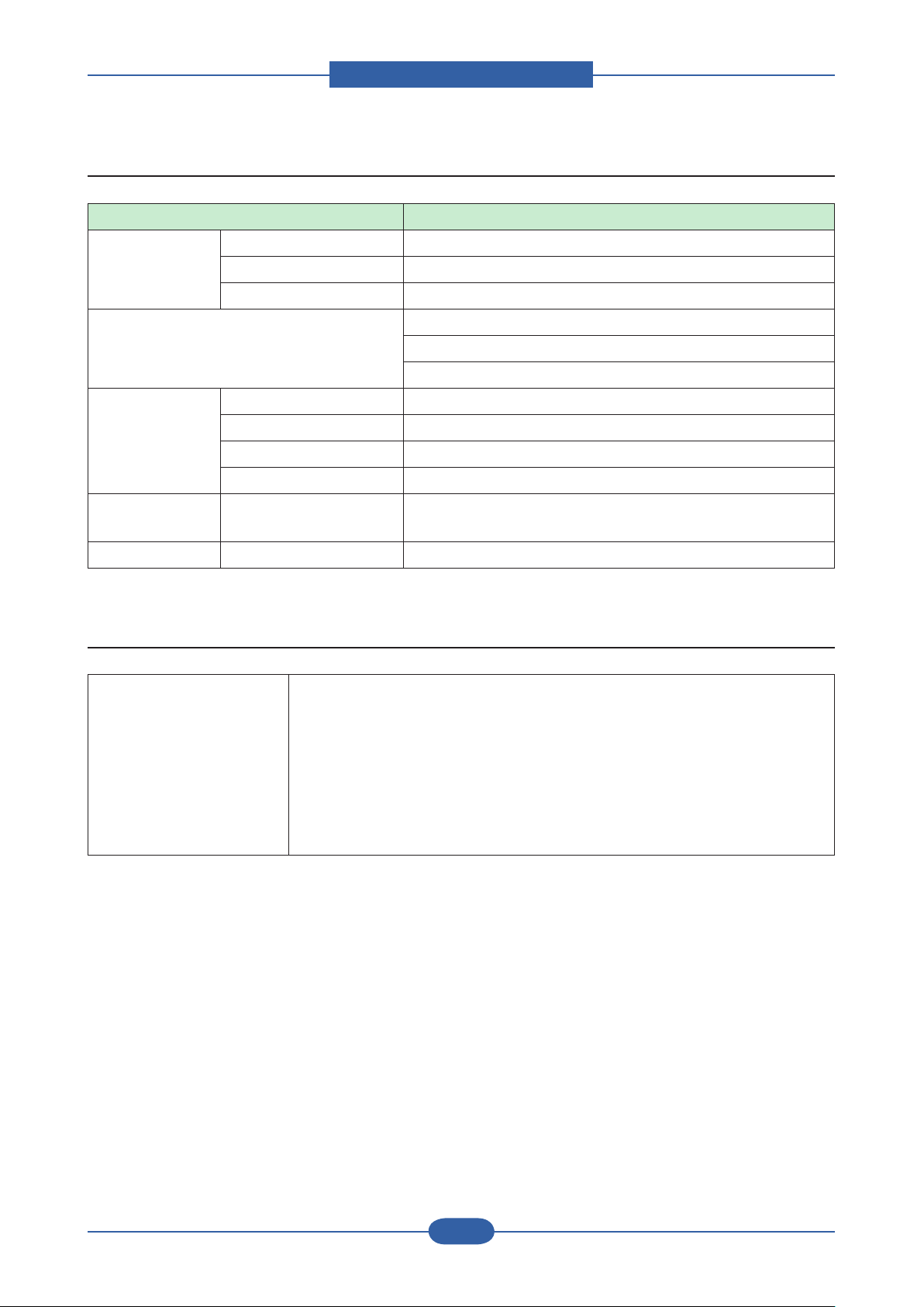
2.2.7 Consumables
■ CRU
Item Description
Toner Cartridge Yield Initial : 3,500 standard pages
Sales : 7,000 standard parge
Part Name CLT-C609S(Cyan)
CLT-M609S(Magenta)
CLT-Y609S(Yellow)
CLT-K609S(Black)
**Region:
CLT-C6092S (Cyan)
CLT-M6092S (Magenta)
CLT-Y6092S (Yellow)
CLT-K6092S (Black)
Key Unique, Electronic key(s-Chip V2.0)
Life detect Life detect Sensor (None), Traced via software
90% exhausted: Low message
100% exhausted: Empty message
Paper Transfer
Belt
* Declared yield value in accordance with ISO/IEC 19798
** Albania, Austria, Belgium, Bosnia, Bulgaria, Croatia, Cyprus, Czech Republic, Denmark, Finland, France,
Germany, Greece, Hungary, Italy, Macedonia, Netherlands, Norway, Poland, Portugal, Romania, Serbia,
Slovakia, Slovenia, Spain, Sweden, Switzerland, UK.
Yield 50K
Part Name CLT-T609
Key Unique, Electronic key(s-Chip V1.1)
Sensor None, that would be traced via software
■ FRU
Item Part_Code Life
Fuser JC96-05454A(110V)
JC96-05455A (220V)
Pick-up Roller JC90-00932A 100K
100K
Friction Pad(CST) JC97-03467A 100K

Product spec and feature
Service Manual
2-8
Samsung Electronics
2.2.8 Option
Item Part Name Description
Memory ML-MEM160
ML-MEM170
Optional Tray 2/3 CLP-S770A 500- sheet Cassette
Jscribe Enabler Kit SCX-KIT10J
Wireless LAN* ML-NWA30L
Hard Disk ML-HDK420 80GB
Stand ML-DSK20S
* Depending on your country, wireless LAN cards may not be available. Contact your local Samsung dealer
or the retailer where you bought your printer.
256 MB
512 MB
Product spec and feature
Service Manual
2-9
Samsung Electronics
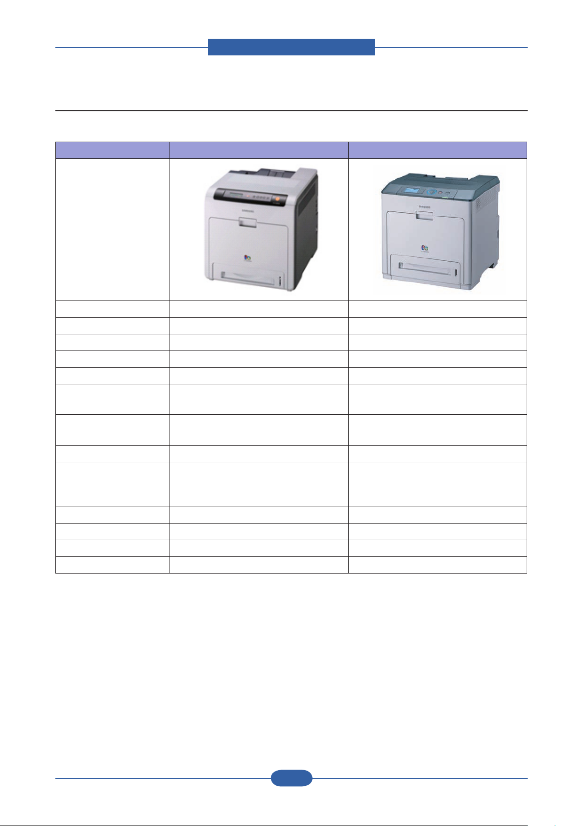
2.3 Model Comparison Table
■ Samsung Model
Dali (CLP- 660ND) Cezanne (CLP- 770ND)
Image
Speed (A4) 24/24 ppm (A4) 32/32 ppm (A4)
Resolution 2,400 x 600 dpi up to 9600 X 600 dpi effective output.
Emulation PDL PDL
Warm-up 30 sec 25 sec
FPOT (Sleep) 44 sec (Color/Mono) 30sec (Color) / 28sec (Mono)
Memory 128 MB
(Max.640 MB)
Interface N/W, USB 2.0 N/W, USB 2.0, EDI
Duplex Standard Standard
Paper Capacity 250 CST, 100 MP
500 SCF x 1
(Max. 850 sh)
Toner 5.5K/5K 3.5K / 7K
Max.Duty 85,000 120,000
Set life 200,000 300,000
HDD N/A HDD option
256 MB
(Max.768 MB)
Wireless Opt.
500 CST, 100 MP
500 SCF x 2
(Max. 1,600 sh)
Product spec and feature
Service Manual
2-10
Samsung Electronics
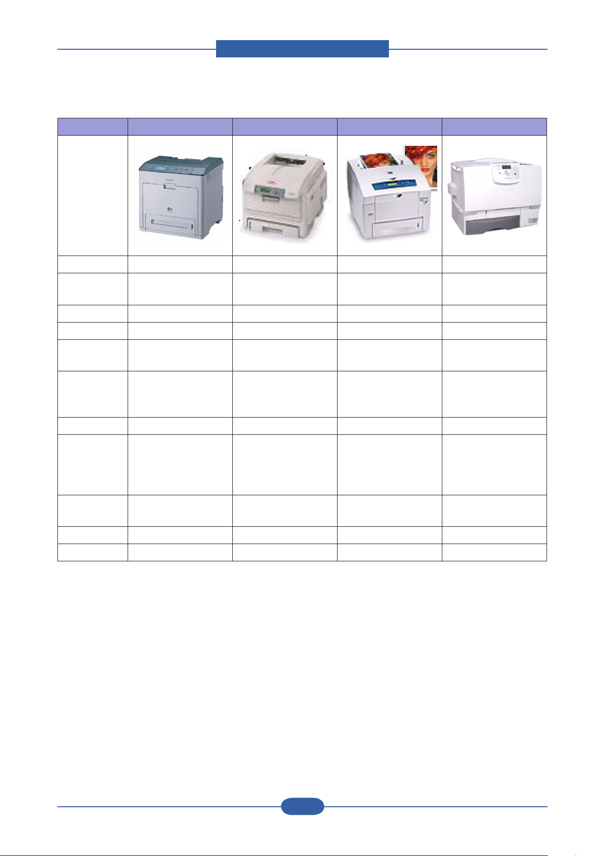
■ Competitor Model
CLP- 770ND OKI C6100N Xerox P8560DN Lexmark C780N
Image
Speed(A4) 32/32 ppm 32/26 ppm 30/30 ppm 33/29 ppm -
Resolution
Up to 9600 x 600
effective output
1,200 x 600 dpi Up to 4,800 dpi Up to 4,800 dpi
Emulation PDL PDL PDL PDL
FPOT 11/10sec
Memory
Interface
256 MB
(Max.768 MB)
N/W, USB 2.0, EDI
Wireless Opt.
11/9 sec 5/5 sec
256 MB
(Max.768 MB)
N/W, USB 2.0
Wireless Opt.
(Max.1GB)
N/W, USB 2.0
600 MB
11/13 sec
256 MB
(Max.768 MB)
N/W, USB 2.0, Direct
USB
Wireless Opt.
Duplex Standard Standard Standard Standard
300 CST, 100 MP
530 SCF
(Max. 930 sh)
Paper
Capacity
500CST, 100 MP
500 SCF x 2
(Max. 1,600 sh)
Toner 3.5K/ 7K 6K/5K 6.8K/3.4K
525 CST, 100 MP
525 SCF x 2
(Max. 2,200 sh)
500 CST, 100 MP
500 SCF
(Max. 1,150 sh)
6K/6K
10K/10K
Max. Duty 120,000 60,000 85,000 120,000
HDD HDD option HDD option HDD option HDD option
Product spec and feature
Service Manual
2-11
Samsung Electronics
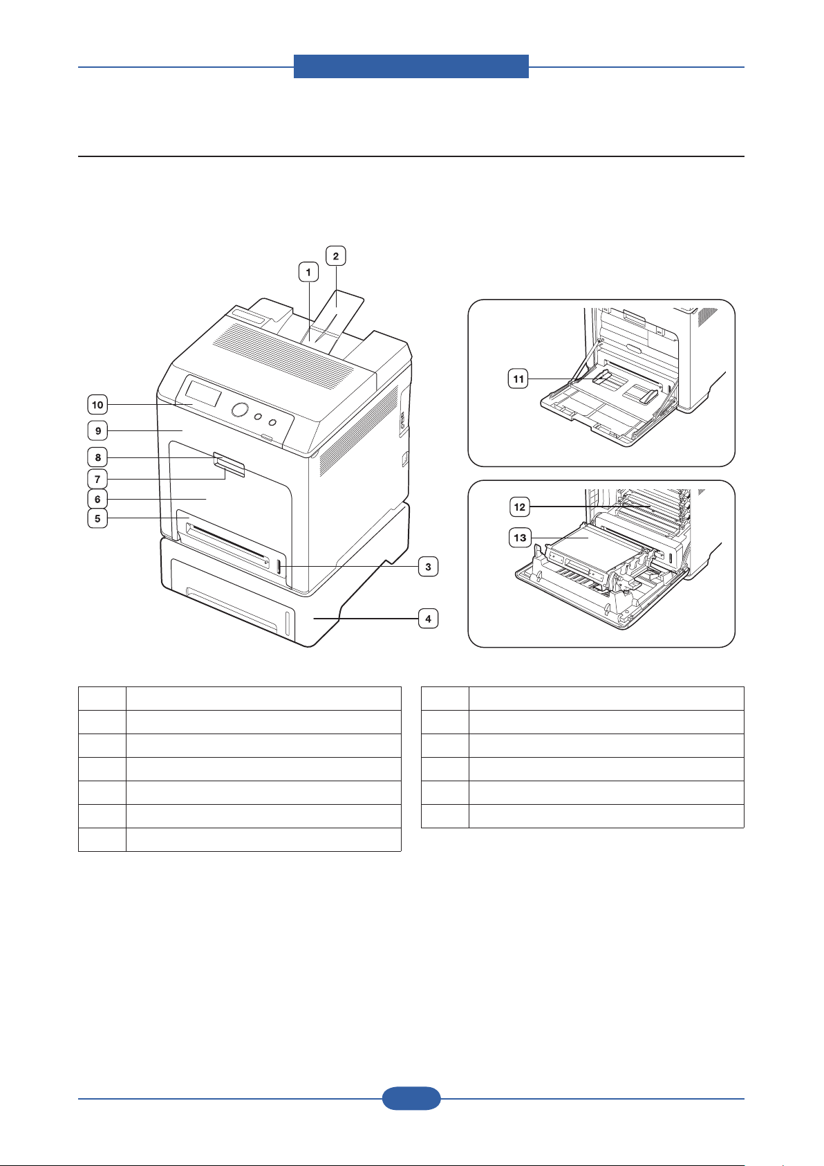
2.4 Product Conguration
■ Front View
1 Output tray
2 Output support
3 Paper level indicator
4 Optional tray
a
5 Tray 1
6 Multi-purpose tray
7 Multi-purpose tray handle
8 Front cover handle
9 Front cover
10 Control panel
11 Multi-purpose tray paper width guides
12 Toner cartridge
13 Paper transfer belt
a.The symbol a is a mark for the optional device.
Product spec and feature
Service Manual
2-12
Samsung Electronics
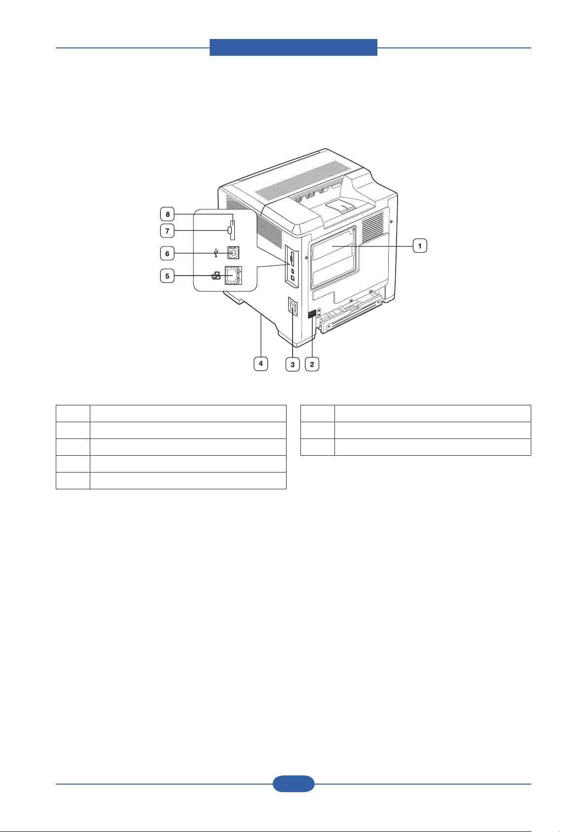
■ Front View
1 Control board cover
2 Power receptacle
3 Power-switch
4 Handle
5 Network port
6 USB port
7 External device interface (EDI)
8 IEEE 802.11 b/g Wireless LAN
a. External device interface for Samsung and third party
solutions.
b.The symbol a is a mark for the optional device.
a
b
Product spec and feature
Service Manual
2-13
Samsung Electronics
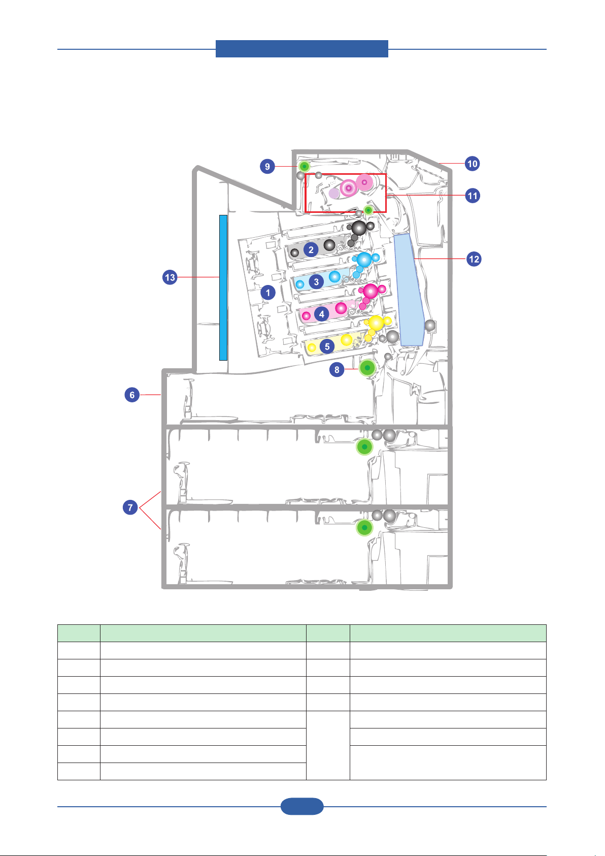
■ System Layout
No. Item No. Item
1 LSU Unit 9 Exit Roller
2 Toner (K) 10 OPE Unit
3 Toner (C) 11 Fuser Unit
4 Toner (M) 12
5 Toner (Y) 13 Main PBA
6 CASSETTE Unit SMPS PBA
7 SCF Unit (Optional Tray) FDB (Fuser Drive Board) PBA
8 Pick up Roller
PTB Unit
Product spec and feature
Service Manual
2-14
Samsung Electronics
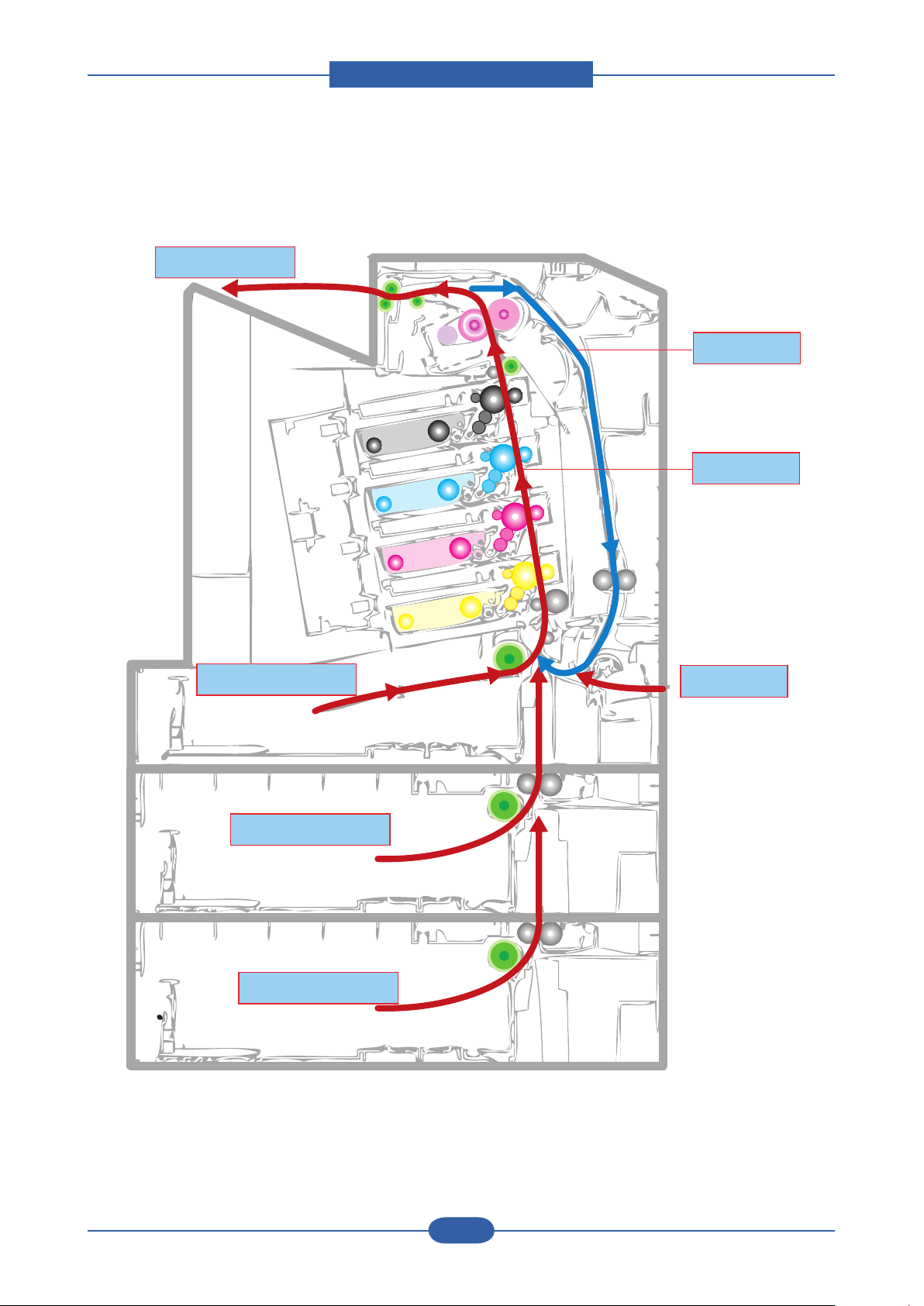
■ Paper Path
Cassette Feed
SCF1 Feed
SCF2 Feed
SimplexPass
Duplex Pass
Exit Pass
MP Feed
Cassette Feed
SCF1 Feed
SCF2 Feed
SimplexPass
Duplex Pass
Exit Pass
MP Feed
Cassette Feed
SCF1 Feed
SCF2 Feed
Cassette Feed
SCF1 Feed
SCF2 Feed
SimplexPass
Duplex Pass
Exit Pass
MP Feed
SimplexPassSimplexPass
Duplex Pass
Exit Pass
MP Feed
Duplex PassDuplex Pass
Exit Pass
MP Feed
Exit Pass
MP Feed
Product spec and feature
Service Manual
2-15
Samsung Electronics
20
1
11
2
12
10
3
9
8
4
7
6
5
13
14
151617
18
19
21
23
22
24
25
26
27
28
29 30
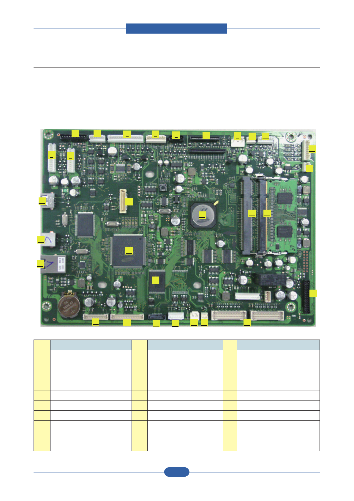
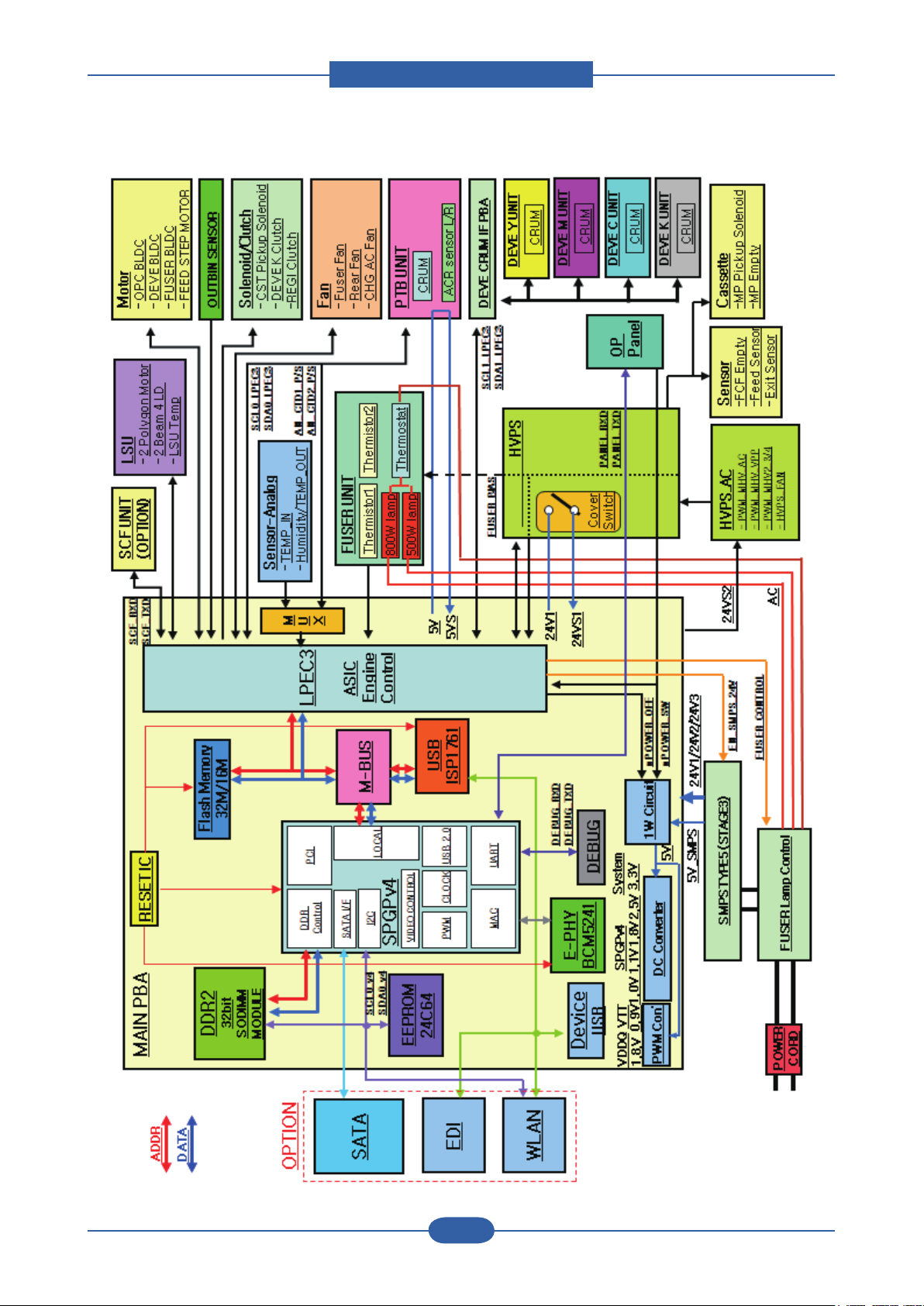
2.4.1 Main PBA
The CLP-770ND system controller consists of a main controller and an engine controller in one-board. The
main controller uses a ARMS core chip as main processors, which are dedicated for printing several internal
operating blocks through system programs stored in Flash Memory. The engine controller has an engine
control SoC, which includes motor drivers, PWM drivers, LSU drivers, sensors, high-voltage drivers, and
other driving units for mechanical parts.
NO. Connector NO. Connector NO. Connector
1 BLDC DEVE, 12pin 11 FUSER TEERMISTOR, 6pin 21 SCF_HVPS I/F, 13pin
2 BLDC OPC, 10pin 12 PTL, 8pin 22 ETHERNET JACK,3722-002376
3 PTB, 14pin 13 REAR FAN, 3pin 23 USB DEVICE JACK, 3722-002303
4
5 BLDC FUSER, 15pin 15 DUAL BEAM LSU, 25 USB WLAN
6 SENSER TEMP, 8pin 16 LSU TEMP, 2pin 26 SPGPV4
7 DEVE CRUM, 7pin 17 SATA POWER CON., 2pin 27 LPEC3
8 HVPS 18 FUSER HEAT CONTROL, 6pin 28 Flash ROM (32MB)
9 COVER ON/OFF, 2pin 19 SATA I/F 29 DDR2 SOCKET(EXTEND)
10 OUT BIN SENSER, 3pin 20 SCF I/F, 18pin 30 DDR2 SOCKET(BASE)
STEP FEED + REGI CLUTCH, 6pin
14 SMPS TYPE5, 28pin 24 USB HOST JACK, 3722-001051
Product spec and feature
Service Manual
2-16
Samsung Electronics
1) Main PBA (SPGPV4) Block Diagram

Product spec and feature
Service Manual
2-17
Samsung Electronics
2) Main PBA Specication
• CPU
- ARM v5TE compliant core 800MHz (I-Cache : 32KB, D-Cache : 32KB)
• Memory Interface
> ROM
- Nor Flash used (32MB)
- Interface With SPGPXV4 ROM Controller
> SDRAM
- Size : CLP-770ND(DDR2) : Default 256MB (Option 256MB/512MB)
> EEPROM
- Size : 512kb
- Interface With SPGPV4 I2C Controller
> CRUM
- Size : 256Byte
- Interface With LPEC3I2C Controller via Deve Crum IF B’D
• I/O Interface
> USB
- DEVICE : High Speed USB 2.0 (High speed 480Mbps)
- Host : J-SCRIBE Enabler Kit (Full speed 12Mbps)
> N/W Embedded
- SPGPV4 With MII Interface
- Active LED(Yellow) / Link LED(Green)
> PWM
- High Voltage Control With Duty
- Main Motor Clock
> I2C Interface
- NVRAM (system information + network information)
- CRUM
Product spec and feature
Service Manual
2-18
Samsung Electronics
HVPS_MAIN
MAIN BOARD
LPEC3
SMPS Type5
PTB
ACR sensor
5V
5V_SMPS
24V2
24V1
5VS
Cover open
Switch
relay
24V1
24VS1
24V2
24VS2
5VL 5VLSU
24VS1
24VS2
3.3V_CRUM
3.3V
24V_ENABLE
Fuser BLDC
MP clutch
LSU_MOTOR
24V2
DEV CRUM
LSU LD,BD
FDB (FUSER_ON)
BLDC DEV
FEED STEP
SCF
clutch Dev K
CST Pick UP
REGI Clutch
FAN_FUSER
FAN_REAR
24V1
5V 5VS
PANEL
5V
V4
nPower_OFF
nCRUM_Power
drawer
HVPS_SUB
FAN_HVPS
OPC BLDC
24V3
24V3
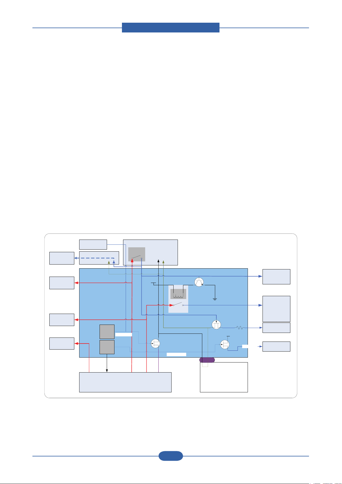
3) Power Flow
Main PBA
- Supply From SMPS +5V
- Power Supply with Regulator (3.3V & 1.8V & 1.1V & 1.0V & 0.9V : Switching Regulator)
- 3.3V : I/O Operating (Digital & Analog)
- 1.8V : DRAM & Video I/F Voltage
- 1.1V : SPGPV4 CPU Voltage
- 1.0V : SPGPV4 Core Voltage
HVPS
- High Voltage Source for EP Condition
- Supply From SMPS +24V
- Controlled By PWM Pulse & I/O
SMPS
- Type 5 (stage 3 type)
- +24V : For use Mechanical Part (Motor & Actuator (Solenoid, Clutch))
- +5V : Logic, Analog, Sensor,
Product spec and feature
Service Manual
2-19
Samsung Electronics
Varistor
1
2
24V Fuse
5V Fuse
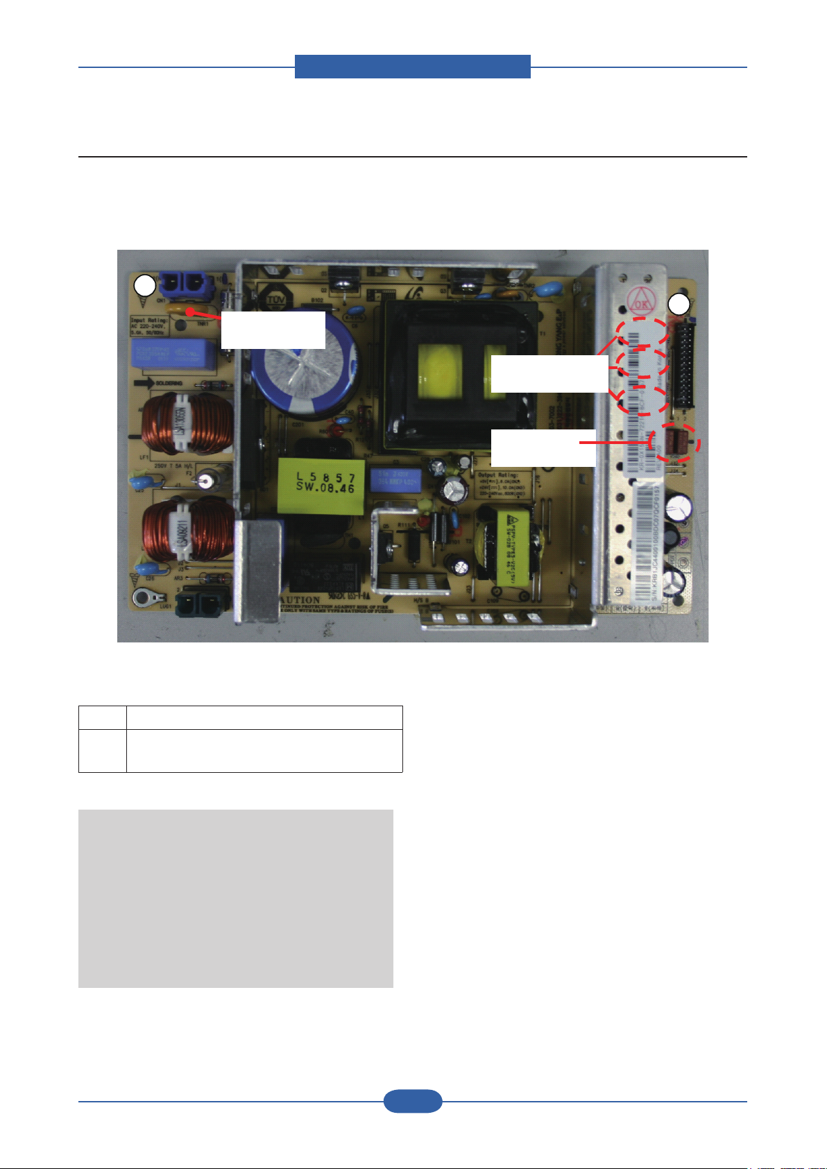
2.4.2 SMPS Board
SMPS( Switching Mode Power Supply ) Board supplies electric power to a Main Board and other boards
through a Main Controller by +5V,+24V from 110V/220V power input. It has safety protection modes for over
current and load.
■ Connection
1 INPUT_AC (from Fuser Drive Board)
2 OUTPUT_5V , 24V (to Main PBA)
INPUT_24V_Control (from Main PBA)
SPECIFICATION
General Input/Output Voltage
1) AC 110V (90V ~ 135V)
2) AC 220V (180V ~ 270V)
3) Output Power: 192W / Max. 270W
DC 5V: 24W ~ 30W
DC 24V: 168W ~ 240W
Product spec and feature
Service Manual
2-20
Samsung Electronics
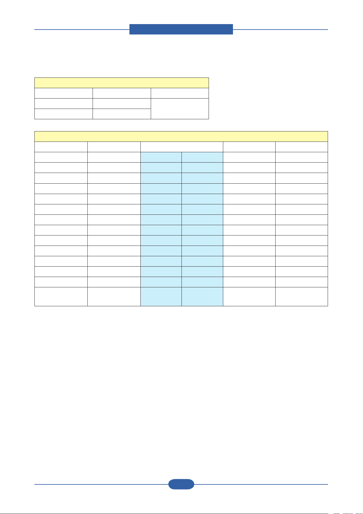
Input / Output connector
◆
AC Input Connector( CN1 )
PIN ASSIGN PIN NO Description
1 AC_L
2 AC_N
AC Input Connector( CN1 )
Description PIN NO PIN ASSIGN PIN NO Description
Power +24V1 1 2 GND 24V Ground
Power +24V1 3 4 +24V1 Power
24V Ground GND 5 6 GND 24V Ground
Power +24V2 7 8 GND 24V Ground
Power +24V2 9 10 +24V2 Power
24V Ground GND 11 12 GND 24V Ground
Power +24V3 13 14 GND 24V Ground
Power +24V3 15 16 GND 24V Ground
5V Ground GND 17 18 GND 5V Ground
Power +5V1 19 20 GND 5V Ground
Power +5V1 21 22 +5V1 Power
5V Ground GND 23 24 GND 5V Ground
AC Input
Power +5V2 25 26 +5V2 Power
Signal Standby 27 28 reserved
Signal
(reserved)
 Loading...