

Page 1
7
7
7-1
Samsung Electronics
Alignment & Adjustments
Service Manual
7. Alignment and Adjustments
This chapter describes some of the main service procedures including:
Using the EDC mode; Clearing paper jam and test patterns.
Much of this chapter is also included in the user's guide.
7.1. Paper path and Paper jam
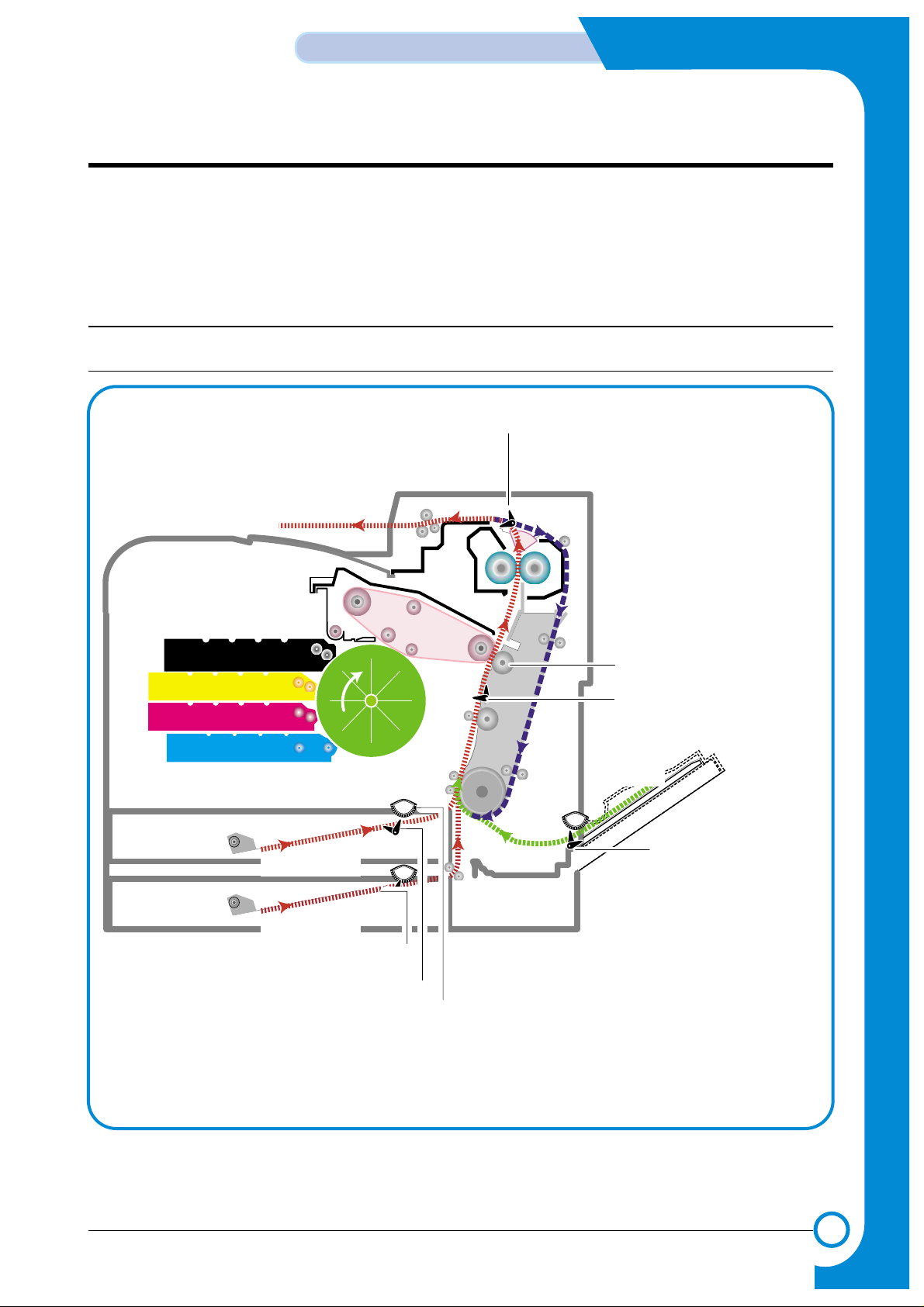
7.1.1 Paper path
DEV. - Black
DEV. - Yellow
Pick-up
Roller
DEV. - Magenta
DEV. - Cyan
CASSETTE
Feeder
DUPLEX
Fuser Unit
EXIT Ass’y
MPF Path
Duplex PathDuplex Path
MPFMPT
DEV. - Black
DEV. - Yellow
OPCOPC
DEV. - Magenta
DEV. - Cyan
SCF
SCF
FCF
ITBITB
Feeder
DUPLEX
Fuser Unit
EXIT Unit
SCF Path
Transfer Roller
Exit Sensor
Paper Pick-Up Roller
Paper Empty Sensor(FCT)
Paper Empty Sensor(SCT)
Paper Empty Sensor(MPT)
Feed Sensor
SCT Path
FCT Path
MPT Path
Page 2
7-2
Alignment & Adjustments
Samsung Electronics
Service Manual
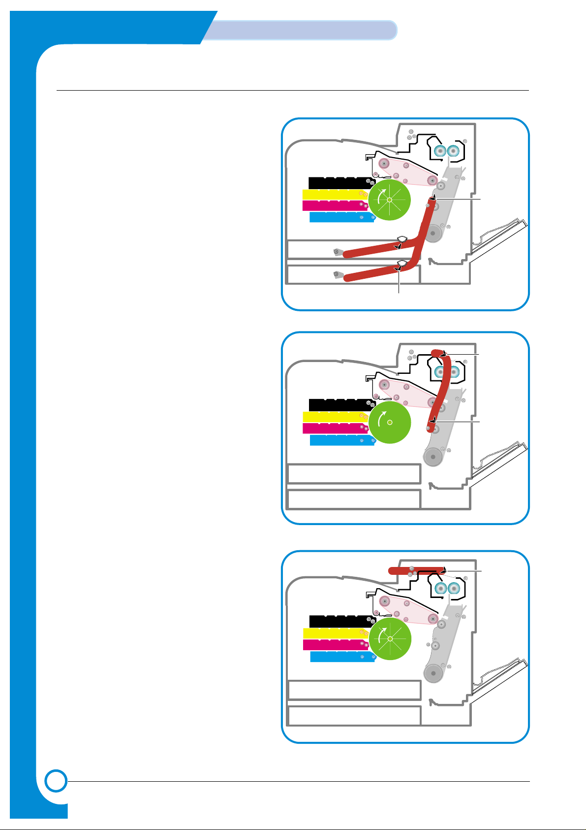
7.1.2 Jams
1) Jam0 (Jam in feed area)
* After a page was picked up, it was not fed.
* Paper does not reach the feed sensor in a
certain time.
* Feed sensor is faulty and does not detect
paper.
- FCF pickup error: When a paper is not
picked up in the 1st cassette.
- SCF pickup error: When a paper is not
picked up in the 2nd cassette.
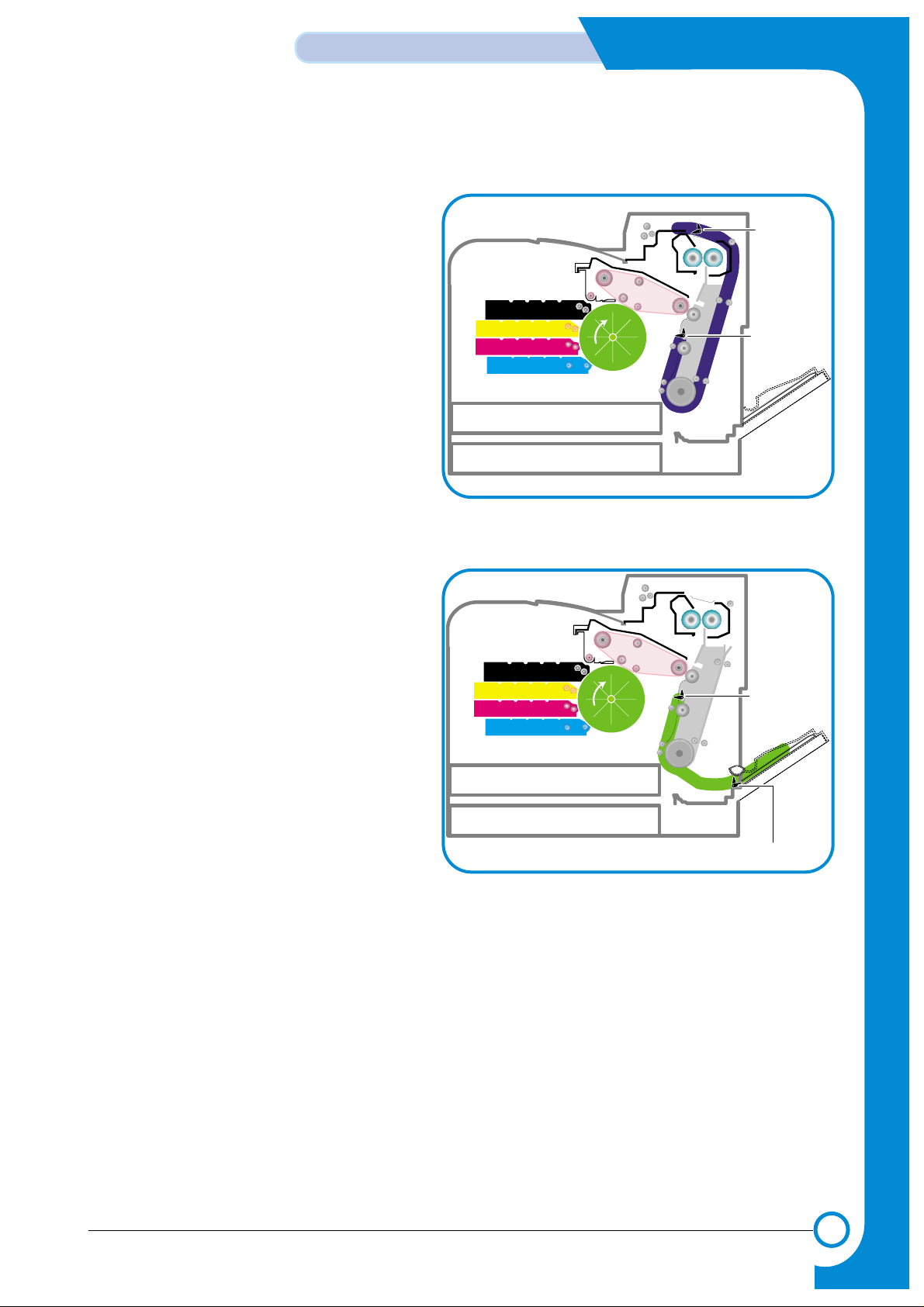
2) Jam1 (Jam inside printer)
* After the leading edge of the paper has
reached the feed sensor, the feed sensor
doesn't turn off (fails to detect the trailing edge
of the paper) in a certain time
* After the leading edge of the paper has
passed the feed sensor, it doesn't reach the
exit sensor in a certain time.
* Exit senor is faulty and does not detect paper.
3) Jam2 (Jam in exit area)
* After the leading edge of the paper has
passed, the trailing edge of the paper has not
passed the exit sensor within a certain time
* The paper drive motor has been driving for
longer than the time needed for the longest
paper size and the exit sensor is not off.
Pick-up
Roller
Feed Sensor
Paper Empty Sensor
Exit Sensor
Feed Sensor
Exit Sensor
Page 3
7-3
Samsung Electronics
Alignment & Adjustments
Service Manual
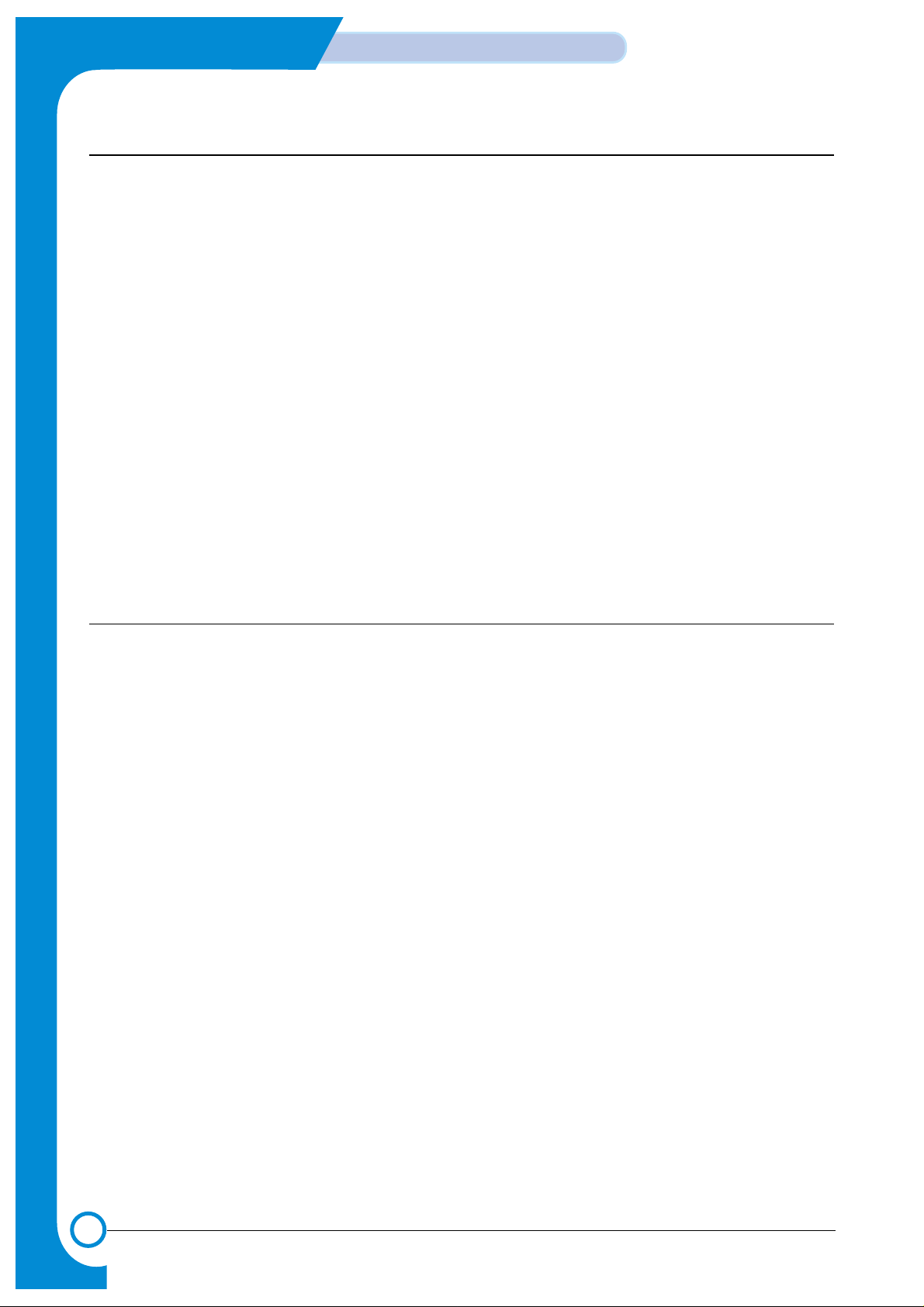
4) Jam duplex (Jam in duplex area)
* Jam duplex occurs when printing the reverse
side of the paper during duplex printing. After
printing the front side the duplex solenoid must
operate in order to feed the paper back into the
duplex path. If the solenoid fails paper may be
stuck in the exit roller and is not fully elected
into the exit tray
* If the duplex solenoid operates paper is fed
back into the machine. If the leading edge of
the paper does not reach the feed sensor in a
certain time then Jam Duplex occurs.
- This can be cause by paper being jammed
in the duplex path area.
5) Jam MPF
* Paper could not be picked up from the MPF tray.
* After pickup, a paper has been fed, but it
doesn't reach the feed sensor in a certain time.
* Feed sensor is faulty and does not detect paper.
Exit Sensor
Feed Sensor
CASSETTE
SCF
SCF Path
MP Empty Sensor
Feed Sensor
Page 4
7-4
Alignment & Adjustments
Samsung Electronics
Service Manual
7.2 Jam Removal
When a jam occurs while printing a jam message is displayed on the control panel.
* Jam0 In Tray 1:
Paper jam in the main cassette.
* Jam0 In MP Tray:
Paper jam in the MP tray
* Jam0 Tray2:
Paper jam in the SCT (Second cassette tray)
* Jam Inside Printer:
Jam 1, Paper is jammed inside the printer.
* Jam In Exit Area:
Jam2, Paper is jammed in the exit area when ejecting paper.
* Jam In Duplex Path:
While duplex printing, paper is jammed in the duplex unit.
CAUTION: When removing jammed paper, always pull it firmly and evenly without any sudden jerks. If
at all possible, remove the paper as a single sheet. If the paper tears ensures ALLpaper
fragments are removed. Any fragments left inside the machine will cause it to jam again.
7.2.1 Factors that cause paper to jam
- Too much paper is loaded in the cassette.
- Paper in not loaded correctly in the cassette.
- Duplex cover opened while printing.
- Cassette removed while printing.
- Incorrect thickness of paper used.
- Incorrect size of paper used.
- Cassette paper guides not correctly set (loose or too tight).
- Foreign object or other contamination of internal paper path and paper guide ribs.
- Badly damaged or folded leading or trailing edges of the paper.
Page 5
7-5
Samsung Electronics
Alignment & Adjustments
Service Manual
7.2.2 Tips for Avoiding Paper Jams
By selecting the correct paper types, most paper jams can be avoided. If a paper jam occurs, follow the
steps outlined below:
• Ensure that the adjustable guides are positioned correctly.
• Do not overload the tray. Ensure that the paper is below the paper capacity mark on the right
inside the tray.
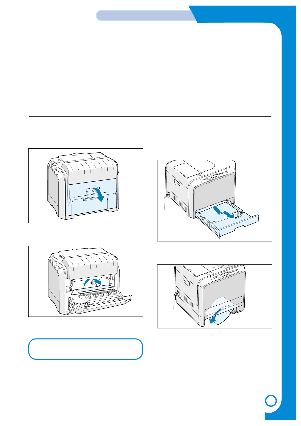
7.2.3 Jam 0 In Tray 1
If paper is jammed in the paper feed area,'Jam0 In Tray1 ' appears on the display.
1. Using the handle open the right cover.
2. Carefully remove the misfed paper in the
direction as shown.
3. Close the right cover .The printer resumes printing.
4. Pull the tray open. After you pull it all the way
out lift up the front part of the tray slightly to
release the tray from the machine.
5. Remove the jammed paper by gently pulling it
straight out.
6. To replace the tray lower the rear edge, align it
to the slot and slide it into the printer.
7. Close the right cover .The printer resumes printing.
If there is any resistance, and the paper
does not move immediately when you pull,
stop pulling and go to step 4.
Page 6
7-6
Alignment & Adjustments
Samsung Electronics
Service Manual
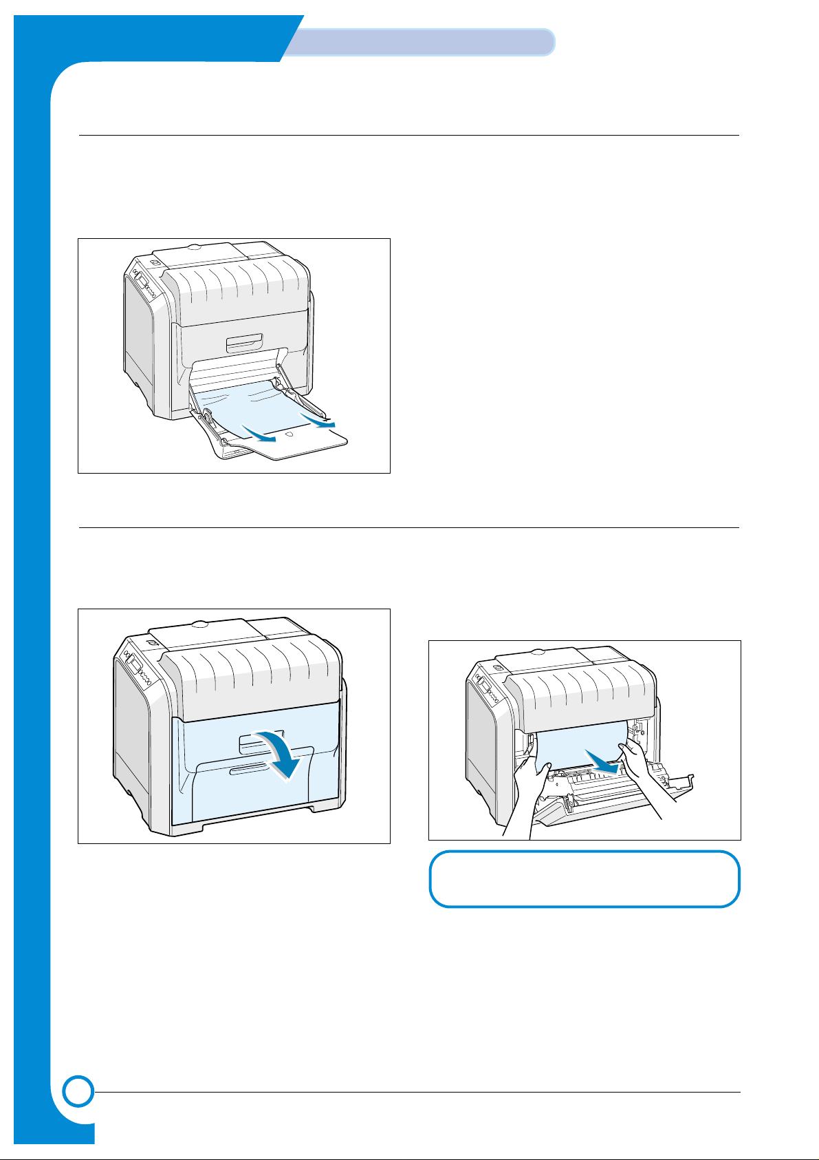
1. If the paper is not feeding properly pull the
paper out of the machine..
2. To resume printing, open and close the right
cover.
7.2.4 Jam 0 in MP Tray 1
'Jam0 In MP Tray' appears on the display when you are printing using the Multi-purpose Tray and the printer detects either there is no paper or the paper is improperly loaded.
1. Using the handle open the right cover. 2. Remove the jammed paper in the direction
shown. To avoid the paper tearing pull it out
gently and slowly.
3.Close the right cover. The printer resumes
printing.
7.2.5 Jam Inside Printer : Jam1
‘If paper is jammed inside the printer 'Jam Inside Printer' appears on the display.
NOTE : If the paper tears make sure that
all of the paper fragments are
removed from the printer.
Page 7
7-7
Samsung Electronics
Alignment & Adjustments
Service Manual
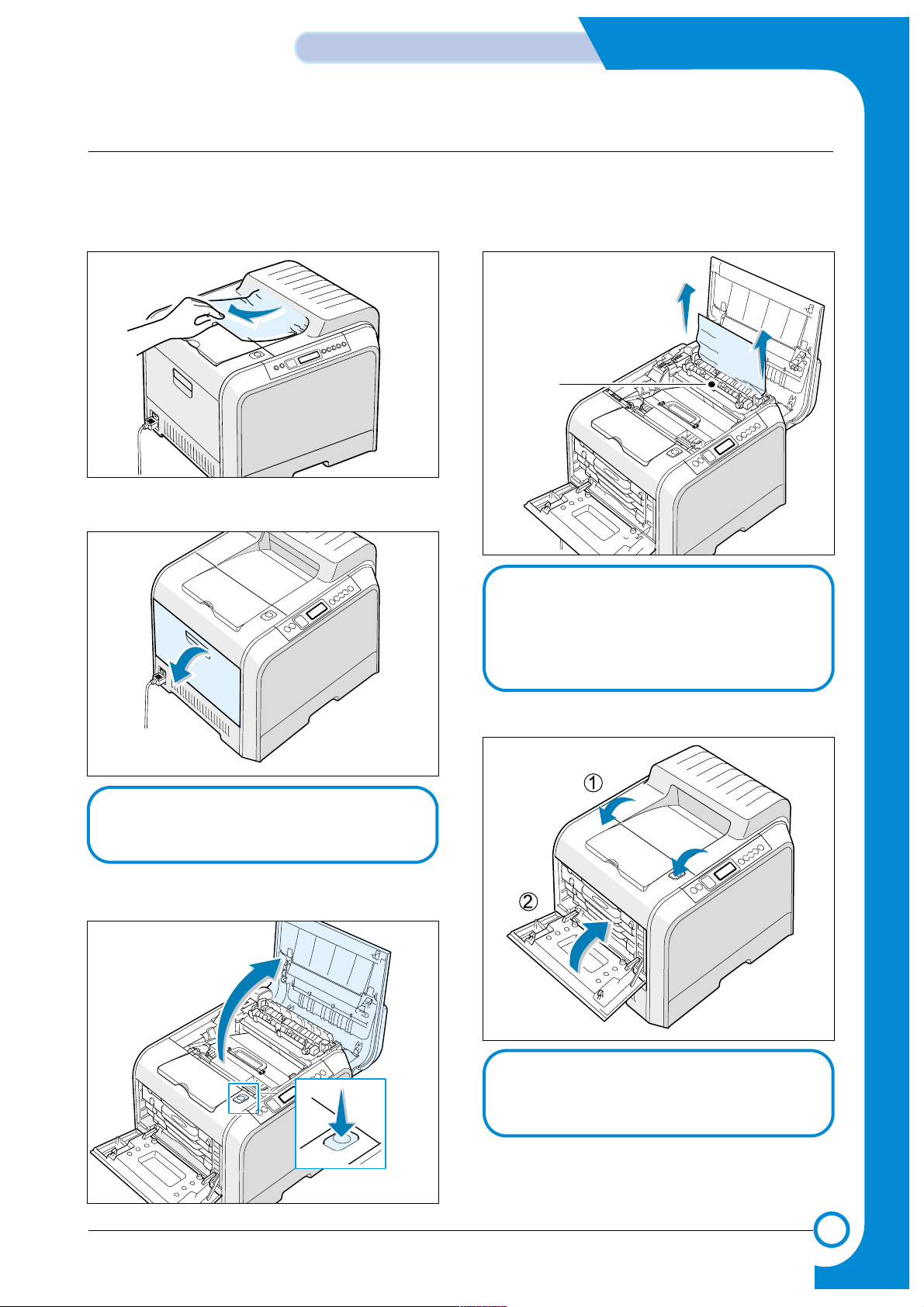
7.2.6 Jam In Exit Area : Jam2
If paper is jammed in the paper exit area 'Jam In Exit Area ' appears on the display.
1. If a long portion of the paper is visible pull it
straight out. If not continue to step 2.
2. Using the handle open the left cover completely.
3. Press the top cover release button to unlatch
the top cover and open it all the way.
4. Carefully take the jammed paper out of the
printer.
5. Close the top cover and the left cover firmly
6. Open and close the right cover to resume printing.
CAUTION : If the left cover is not completely
open the top cover release button
will not press.
Fuser
CAUTION : Do not touch the fuser it is hot and
could cause burns! The fuser's
operating temperature is 180 °C
(356 °F). Take care when removing
paper from the machine.
CAUTION : Do not try to close the top cover with
the left cover closed. This may cause
damage to the machine.
Page 8
7-8
Alignment & Adjustments
Samsung Electronics
Service Manual
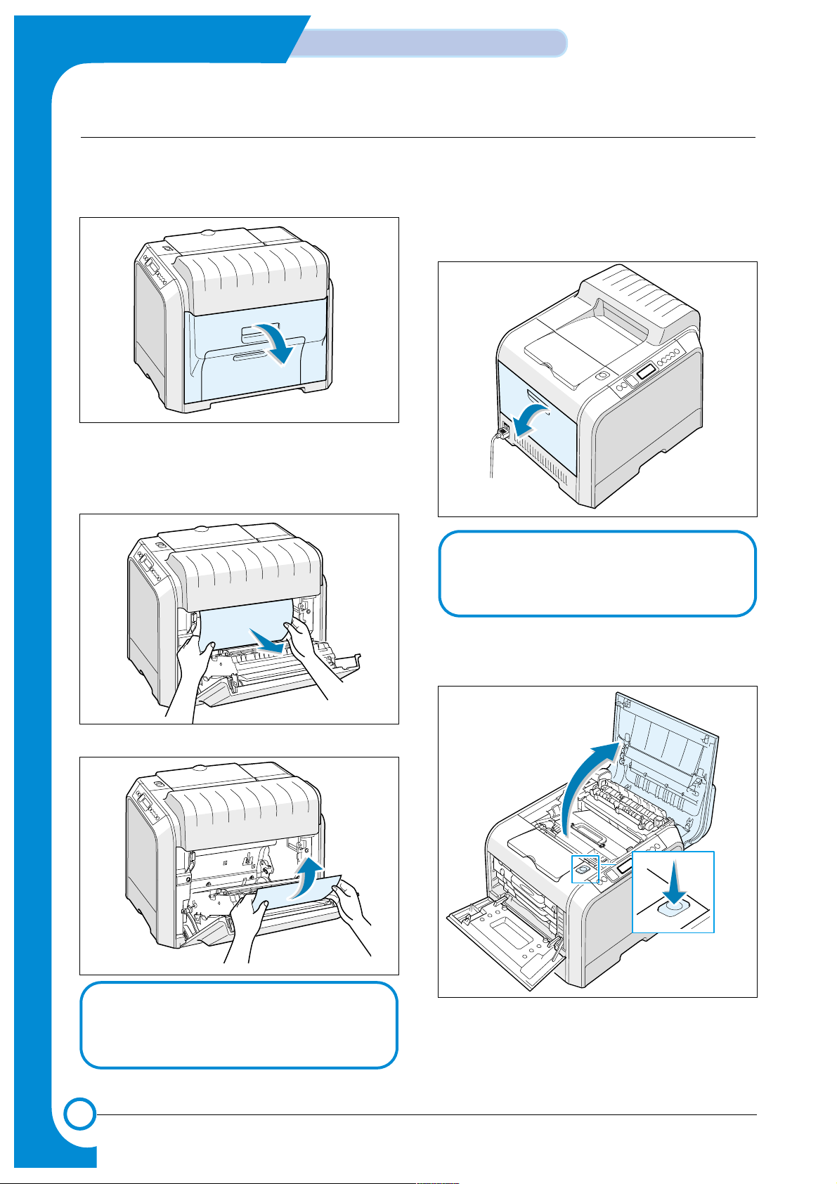
7.2.7 Jam In Duplex Path : Jam Duplex
If paper is jammed in the duplex area 'Jam In Duplex Path' appears on the display.
1. Using the handle open the right cover.
2. Locate the jammed paper and then pull it out
gently and slowly to avoid the paper tearing.
Close the right cover. The printer resumes printing.
or
3. If you cannot find the jammed paper or there is
any resistance removing the paper go to step 4.
4. Using the handle open the left cover completely.
5. Press the top cover release button to unlatch
the top cover and open it all the way.
CAUTION : If the left cover is not completely
open the top cover release button
will not press.
Note : If the paper tears make sure that all of the
paper fragments are removed from the
printer.
Page 9

7-9
Samsung Electronics
Alignment & Adjustments
Service Manual
6. Locate the jammed paper and then carefully
take it out of the printer.
7. Close the top cover and the left cover firmly
Fuser
CAUTION : Do not touch the fuser it is hot and
could cause burns! The fuser's
operating temperature is 180 °C
(356 °F). Take care when removing
paper from the machine.
CAUTION : Do not try to close the top cover
with the left cover closed. This may
cause damage to the machine.
Page 10

7-10
Alignment & Adjustments
Samsung Electronics
Service Manual
7.2.8 Jam In the Optional Second Tray
1. Using the handle open the right cover.
2. Remove the jammed paper in the direction
shown. To avoid the paper tearing pull it out
gently and slowly.
3. Close the right cover. The printer resumes
printing.
4. If you cannot find the jammed paper in the
machine open the Tray2 outer jam cover.
5. Open the inner cover of Tray 2.
6. Pull the jammed paper out in the direction
shown. To avoid the paper tearing pull it out
gently and slowly. If there is any resistance, and
paper does not move immediately when you
pull, stop pulling and continue to step 8.
Page 11

7-11
Samsung Electronics
Alignment & Adjustments
Service Manual
7. Close the two jam covers. Go to step 11.
8.Pull the optional tray, Tray 2, out of the printer.
9. If you see the jammed paper remove the paper
from the machine by gently pulling it straight out.
10. Slide the tray back into the printer and close
the two jam covers.
11. Open and close the right cover. The printer
resumes printing.
Page 12

7-12
Alignment & Adjustments
Samsung Electronics
Service Manual
7.3 Sample Pattern
This product provides several printable test patterns for maintenance purposes. These patterns can be used to aid the
diagnosis of print quality problems.
7.3.1 Printing a Demo Page
Print a demo page to make sure that the printer is operating correctly.
1. Press the Menu button on the control panel until you see “Information ” on the bottom line of the display..
2. Press the Enter button to access the Menu.
3. Press the scroll button until you see “Demo Page ” on the bottom line.
4. Press the Enter button .
A demo page showing the printer ’s features and capabilities prints out.
7.3.2 Printing a Configuration Page
Print a demo page to make sure that the printer is operating correctly.
1. Press the Menu button on the control panel until you see “Information ” on the bottom line of the display..
2. Press the Enter button to access the Menu.
3. Press the scroll button until you see “Configuration ” on the bottom line.
4. Press the Enter button .
A demo page showing the printer ’s features and capabilities prints out.
Page 13

7.4 Checking the Remaining Toner and Others
7.4.1 Checking the Remaining Toner
You can check the level of toner left in each cartridge.
1. In ready mode press the Menu button on the control panel several times until you see ‘Setup ’on the bottom line
of the display.
2 Press the Enter button to access the menu.
3 Press the scroll button until ‘Maintenance ’ displays on the bottom line.
4 Press the Enter button
5 When ‘Check Toner ’displays on the bottom line,,press the Enter button .
6 Press the scroll button until the color of the toner cartridge you want to check displays on the bottom line.
7 Press the Enter button The display shows the percentage of the remaining toner.
8. Press the Upper Level button to return to step 6 and select a different cartridge.
9. To return to the Ready condition press the Upper Level button several times until 'Ready' appears in the display
7.4.2 Checking the Remaining Others
You can check the level of each item.
1. In ready mode press the Menu button on the control panel everal times until you see ‘Setup ’on the bottom line
of the display.
2 Press the Enter button to access the menu.
3 Press the scroll button until ‘Maintenance ’ displays on the bottom line.
4 Press the Enter button
5 When ‘Check Others ’ displays on the bottom line,,press the Enter button .
6 Press the scroll button until the item you want to check displays on the bottom line.
7 Press the Enter button The display shows the percentage of item.
8. Press the scroll button display either 'Image Count' or 'Reset'
9a. Choose 'Reset' and press enter to reset the counter after replacing a consumable item
or
9b Choose Image count to display the counter.
10. Press the Upper Level button to return to step 7 and select a different choice or press it a second time to return to step
6 and choose a different item.
11. To return to the Ready condition press the Upper Level button several times until 'Ready' appears in the display.
7-13
Samsung Electronics
Alignment & Adjustments
Service Manual
Page 14

7-14
Alignment & Adjustments
Samsung Electronics
Traninung Manual
7.5 Understanding the Control Panel
The control panel on the top right side of your printer has a display and seven buttons.
7.5.1 Display
Buttorns
Status Map Display : dispaly the printer
status and job in progress.
Message Description
Ready •The printer is on-line and ready to print.
•If you press On Line/Continue ,the printer switches to off-line.
Offline •The printer is off-line and cannot print.
•If you press On Line/Continue ,the printer switches to on-line.
Processing... •The printer is printing.
•If you want to cancel printing,press Cancel .
Sleeping... •The printer is in Power Save mode, using less power.When a print job is
received from the computer or if any button is pressed,the printer switches to
on-line.
•To deactivate the Power Save mode or change the power-saving time.
Page 15

7-15
Samsung Electronics
Alignment & Adjustments
Service Manual
Message Description
When an error occurs,a lamp turns on at the corresponding location on the Status map.An error
message appears on the display so that you can locate the error.
•Press to switch between on-line and off-line.
•In menu mode,press to return to ready mode.
The color of the On Line/Continue button indicates the status of the printer.
• Press to enter menu mode.
• In menu mode,press to scroll through the menus.
In menu mode,press to select the displayed submenu item or confirm the changed setting.The
selected item is marked with an *.
In menu mode,press to scroll through submenu items or setting options.Pressing • moves you to
the next option and pressing • sends you back to the previous option.
• Press to cancel the current print job.
• In menu mode,press to return to ready mode.
In menu mode,press to go back to the upper menu level.
•The printer is off-line and cannot print.
•The printer is in Power Save mode. When data is received,it switches to on-line.
Green
Orange
Off
On
Blanking
On
Blanking
Status map
The printer is on-line and can receive data from the computer.
• When the backlight blinks slowly,the printer is receiving data from
the computer.
• When the backlight blinks quickly,the printer is receiving and printing data.
The printer stops printing due to a major error.Check the display
message.
A minor error has occured and the printer is waiting for the error to
be cleared.Check the display message.When the problem is
cleared,the printer resumes printing.If you want to ignore this warning,press this button.
7.5.2 Buttons
Page 16

7-16
Alignment & Adjustments
Samsung Electronics
Service Manual
7.5.3 Using Control Panel Menus
A number of menus are available to make it easy for you to change the printer settings.
You can configure your printer from the printer’s control panel.You can also use the control panel menus while the printer
is in use.
1. In ready mode press the Menu button until you see the menu you want on the bottom line of the display.
2. Press the Enter button to access the menu.
3. Press the scroll button until the menu item you want displays on the bottom line.
4. Press the Enter button to confirm the selected item.
5. If the menu item has submenus, repeat steps 3 and 4.
6. Press the scroll button until the setting option you want displays on the bottom line or enter the required value.
7. Press the Enter button to save your input or selection.
- An asterisk (*) appears next to the selection on the display, indicating that it is now the default.
8. To exit the menu, press the Upper Level button repeatedly, or the Cancel button .
- After 60 seconds of inactivity (no key has been pressed), the printer automatically returns to ready mode.
NOTE: Print settings made from the printer driver override the settings on the control panel.
Informa tion Paper Layout Graphics Printer
Configuration Tray Source Orientation
Resolution Default Set
Menu Map Media Size Duplex Current Job
Demo Page Width Duplex Margin
PS3 Font List Custom
Custom
Height Simplex Margin
PCL Font List Media Type Copies
Network PostScript PCL Setup Color
Config. Network Print PS Error Typeface LCD Language Calibration
Reset Network
Symbol
Emulation
Custom Color
Default Set Lines Power Save
Print Net CFG Pitch Auto Continue
Jam Recovery
Altitude Adj.
Auto CR
Job Time Out
Maintenance
Page 17

7-17
Samsung Electronics
Alignment & Adjustments
Service Manual
7.6 Periodic Defective Image
If an image defects appears at regular intervals on the printed-paper, it is due to a faulty or damaged roller.
Refer to the table below and check the condition of the appropriate roller.
No Roller Defective image Typical defect
1 OPC Drum same position in each page white spot on black image or black spot
2 Charge Roller 43.96 mm black spot
3 Supply Roller 31.41 mm light or dark horizontal image band
4 Developing Roller 35.34 mm horizontal image band
5 ITB(T1) same position in each page black spot
6 Transfer Roller(T2) 75.36 mm ghost
7 Heat Roller 109.9 mm Black spot and ghost, printing backside pollution
Page 18

7-18
Alignment & Adjustments
Samsung Electronics
Service Manual
7.7 How to use EDC (Engine Diagnostic Control) Mode
7.7.1 EDC Establishment
EDC Mode is feature that allows the engineer to check the condition of the print engine. It can check the operating condition of the motors, sensors, solenoids and clutches, measure the High Voltage from the HVPS and check the operation of
the fuser and LSU.
7.7.1.1 How to enter the EDC Mode
a) Turn on the printer while pressing the "Enter" key. Hold the key until 'Select Test mode' appears in the display.
b) Press the direction key until "<EDC Test>" is displayed.
c) Press the "Enter" key.
d) <Enter Access Key> appears in the display. Press the cancel key twice.
Note. There are a number of other test modes. Only EDC Test and Panel Tests should be used by service engineers, all
other functions are for factory use only.
7.7.1.1 Functions of the keys on the Panel and how to use them.
Key Function Description
On Line Not used
Cancel Not used
Menu Menu Display Top Menu of EDC Mode
Left/Right Arrow Find Menu Move Menu
Confirm Run/Select Run run the Function / Select Menu
Upper Menu Stop/Move Stop Stop the selected Function or go to Upper Menu.
7.7.1.2 LCD Function and Directions
Upper Line : Upper Line messages mainly show the current test menu or sub-menu.
[Main Menu] or [Function] is displayed.
Lower Line : Lower Line messages mainly the current test and status.
Buttorns
Status Map Display : dispaly the printer
status and job in progress.
Page 19

7-19
Samsung Electronics
Alignment & Adjustments
Service Manual
7.7.2 EDC Whole Menu
Motor Test
Main Motor
Dev Motor
Waste Motor
SCF Motor
Fan Motor
HVPS Test
Solenoid Test
Y Clutch
M Clutch
C Clutch
K Clutch
Y Solenoid
M Solenoid
C Solenoid
K Solenoid
Feed Clutch
T2 Solenoid
FCF Solenoid
MPF Solenoid
SCF Solenoid
ITB Solenoid
Duplex Solenoid
Feed Sensor
Exit Sensor
FCF Empty Sensor
MPF Empty Sensor
SCF Empty Sensor
SCF Cover Sensor
Waste Box Sensor
Cover Check
Sensor Test
LSU Motor
Laser Diode
Fuser
LSU & Fuser Test
Charger
T1
T2
Dev DC
Dev AC
Test Print
Select Tray
Select Pattern
Print Pattern
Print Menu Map
Interface Test
SCF Interface
Page 20

7-20
Alignment & Adjustments
Samsung Electronics
Service Manual
7.7.2.1 Motor Test
This function allows the operation of the various motors to be checked.
<How to operate>
a) Press the "<" or ">" key until "Motor Test" is displayed.
b) Press the "Enter" key to select this function.
c) Press the "<" or ">" key until you see the name of the motor you wish to test.
d) Press the "Enter" key to run the test. The test is stopped by pressing the "Upper Level" key.
e) Pressing the "Upper Level" key when the test is already stopped will return to step 'c' above.
f) Pressing the "Upper Level" key again will return to the EDC main menu.
Item Description Remarks
Main Motor Operates Main Motor Displays "Succeed" if Motor Lock Signal is Normal, "Failed" otherwise.
Dev Motor Operates Dev Motor Displays "Succeed" if Motor Lock Signal is Normal, "Failed" otherwise.
Waste Motor Operates Waste Motor Display motor status - "On" or "Off".
SCF Motor Operates SCF Motor Display motor status - "On" or "Off".
Fan Motor Operates Fan Motor Display motor status - "On" or "Off".
Page 21

7-21
Samsung Electronics
Alignment & Adjustments
Service Manual
7.7.2.2 Solenoid Test
This function allows the operation of various solenoids and clutches to be checked.
<How to operate>
a) Press the "<" or ">" key until "Solenoid Test" is displayed.
b) Press the "Enter" key to select this function.
c) Press the "<" or ">" key until you see the name of the clutch or solenoid you wish to test.
d) Press the "Enter" key to run the test. The test is stopped by pressing the "Upper Level" key.
e) Pressing the "Upper Level" key when the test is already stopped will return to step 'c' above.
f) Pressing the "Upper Level" key again will return to the EDC main menu.
Item Description Remarks
Y Clutch Operates Yellow Developer Clutch Displays clutch status - "On" or "Off".
M Clutch Operates Magenta Developer Clutch Displays clutch status - "On" or "Off".
C Clutch Operates Developer Clutch Displays clutch status - "On" or "Off".
K Clutch Operates Black Developer Clutch Displays clutch status - "On" or "Off".
Y Solenoid Operates Yellow Developer Solenoid Displays solenoid status - "On" or "Off".
M Solenoid Operates Magenta Developer Solenoid Displays solenoid status - "On" or "Off".
C Solenoid Operates Cyan Developer Solenoid Displays solenoid status - "On" or "Off".
K Solenoid Operates Black Developer Solenoid Displays solenoid status - "On" or "Off".
Feed Clutch Operates Feed Clutch Displays clutch status - "On" or "Off".
T2 Solenoid Operates T2 Clutch Solenoid Displays solenoid status - "On" or "Off".
FCF Solenoid Operates FCF pick-up Displays solenoid status - "On" or "Off".
MPF Solenoid Operates MPF pick-up Displays solenoid status - "On" or "Off".
SCF Solenoid Operates SCF pick-up (Only if SCF is fitted) Displays solenoid status - "On" or "Off".
ITB Solenoid Operates ITB cleaning Solenoid Displays solenoid status - "On" or "Off".
Duplex Solenoid OperateS Duplex Solenoid Displays solenoid status - "On" or "Off".
Page 22

7-22
Alignment & Adjustments
Samsung Electronics
Service Manual
7.7.2.3 Sensor Test
This function allows the operation of various sensors to be checked
<How to operate>
a) Press the "<" or ">" key until "Sensor Test" is displayed.
b) Press the "Enter" key to select this function.
c) Press the "<" or ">" key until you see the name of the sensor you wish to test.
d) Press the "Enter" key to display the sensor status. If the sensor actuator is moved the displayed status will change to
reflect the new sensor position..
e) Pressing the "Upper Level" key will return to step 'c' above.
f) Pressing the "Upper Level" key again will return to the EDC main menu.
Item Description LCD indication
Feed Feed Sensor Status "With Paper" is displayed when Paper is detected,
"Without paper" is displayed when paper is not detected.
Exit Exit Sensor Status "With Paper" is displayed when Paper is detected,
"Without paper" is displayed when paper is not detected.
FCF Empty FCF Empty Sensor status "With Paper" is displayed when Paper is detected,
"Without paper" is displayed when paper is not detected.
MPF Empty MPF Empty Sensor Status "With Paper" is displayed when Paper is detected,
"Without paper" is displayed when paper is not detected.
SCF Empty SCF Empty Sensor Status "With Paper" is displayed when Paper is detected,
"Without paper" is displayed when paper is not detected.
SCF Cover SCF Cover Sensor Status "Cover Opened" or "Cover Closed" is displayed.
Waste Box Waste Toner Sensor Status "Not Installed" is displayed when either the Waste toner tank is not installed or
it is full.
"Installed" is displayed when the Waste Toner tank is installed and is not full.
Cover Left or Right Cover Sensor Status "Cover Opened" or "Cover Closed" is displayed.
Page 23

7-23
Samsung Electronics
Alignment & Adjustments
Service Manual
7.7.2.4 LSU & Fuser Test
This function allows the Fuser, LSU Motor and Laser Diode to be tested.
<How to operate>
a) Press the "<" or ">" key until "LSU & Fuser Test" is displayed.
b) Press the "Enter" key to select this function.
c) Press the "<" or ">" key until you see the name of part you wish to test.
d) Press the "Enter" key to run the test. The test is stopped by pressing the "Upper Level" key.
e) Pressing the "Upper Level" key when the test is already stopped will return to step 'c' above.
f) Pressing the "Upper Level" key again will return to the EDC main menu.
• The LSU Motor Lock Time is a maximum 15 seconds depending on the environment. It may take over 15 seconds until
the <Succeed> or <Failed> message is displayed.
• For safety - after printing a test pattern if you need to return to EDC mode turn the printer off and then re-enter EDC.
Item Description Remarks
LSU Motor Operates LSU Motor The LSU motor must come into lock within 6 seconds. After 7 secs the
status is displayed either:
"Succeed" if lock is successful within the time limit
"Failed" if lock is not achieved
LD Operates Laser Diode
Fuser Heats the Fuser Repetitive cycle (10secs) - Lamp on for 500msec then off again.
7.7.2.5 Interface Test
This function tests communications between the Main PBAcontroller and the SCF controller.
<How to operate>
a) Press the "<" or ">" key until "Interface Test" is displayed.
b) Press the "Enter" key to select and run this function.
c) "Succeed" or "Failed" is displayed..
d) Pressing the "Upper Level" key again will return to the EDC main menu.
Page 24

7-24
Alignment & Adjustments
Samsung Electronics
Service Manual
7.7.2.6 Test Print
This function allows you to test the overall function of the print engine. You can select either a 4 * 4 color bar pattern or a
solid color pattern. If the solid pattern is selected 4 pages are printed - one for each color. You can also print the EDC
Mode Menu Map.
<How to operate>
a) Press the "<" or ">" key until "Test Print" is displayed.
b) Press the "Enter" key to select this function.
c) Press the "<" or ">" key until "Select Tray" is displayed.
d) Press the "Enter" key to select this function.
e) Press the "<" or ">" key until required tray is displayed and then press the "Enter Key"
f) Press the "Upper Level" key.
g) Press the "<" or ">" key until "Select Pattern" is displayed.
h Press the "Enter" key to select this function.
i) Press the "<" or ">" key until required pattern is displayed and then press the "Enter Key"
j) Press the "Upper Level" key.
k) Press the "<" or ">" key until "Print Pattern" is displayed.
l) Press the "Enter" key to print the pattern.
For safety - after printing a test pattern if you need to return to EDC mode turn the printer off and then re-enter EDC
Mode by turning power on whilst holding in the "Enter" key.
Page 25

7-25
Samsung Electronics
Alignment & Adjustments
Service Manual
7.7.2.7 HVPS Test
This function allows the HVPS to be tested
<How to operate>
a) Press the "<" or ">" key until "HVPS Test" is displayed.
b) Press the "Enter" key to select this function.
c) Press the "<" or ">" key until you see the name of the voltage you wish to test.
d) Press the "Enter" key to select the test.
e) Press the "<" or ">" key to select the appropriate Duty Cycle and press "Enter" to start the test
The test is stopped by pressing the "Upper Level" key.
The display shows the acceptable range for this setting (column 4 in the table below)
The mid range (nominal) voltage is shown in column 3 in the table below.
e) Pressing the "Upper Level" key when the test is already stopped will return to step 'c' above.
f) Pressing the "Upper Level" key again will return to the EDC main menu.
Item Description
Lower Menu & Input
LCD Indication
V oltage
Charger Supply Voltage to the Charger Duty 50% : -1262V Duty 50% : -1224V ~ -1300V
Duty 80% : -2037V Duty 80% : -1976V ~ -2098V
T1 Supply Voltage to T1 Duty 50% : 1174V Duty 50% : 1139V ~ 1209V
Duty 90% : 2080V Duty 90% : 2018V ~ 2142V
T2 Supply Voltage to T2 Duty 30% : 1800V Duty 30% : 1746V ~ 1854V
Duty 80% : 4540V Duty 80% : 4404V ~ 4676
Reverse Bias : -900V Reverse Bias : -800V ~1200V
Dev DC Supply DC Voltage to Dev Duty 45% : -370V Duty 45% : -359V ~ -381V
Dev AC Supply AC Voltage to Dev Duty 35% : -2200V Duty 35% : -2134V ~ -2266V
* The allowed tolerance is commonly +/- 3%, this is the value Displayed, in case of "Dev AC", it is the value of Vpp.
* T2 Reverse Bias.(Tolerance : +/-20%)
Page 26

7-26
Alignment & Adjustments
Samsung Electronics
Service Manual
MEMO
 Loading...