

Page 1
5
5
5-1
Samsung Electronics
System Outline
Service Manual
5 System Outline
This chapter describes the functions and operating principals of the main components.
5.1 CLP (Color Laser Printing) Process
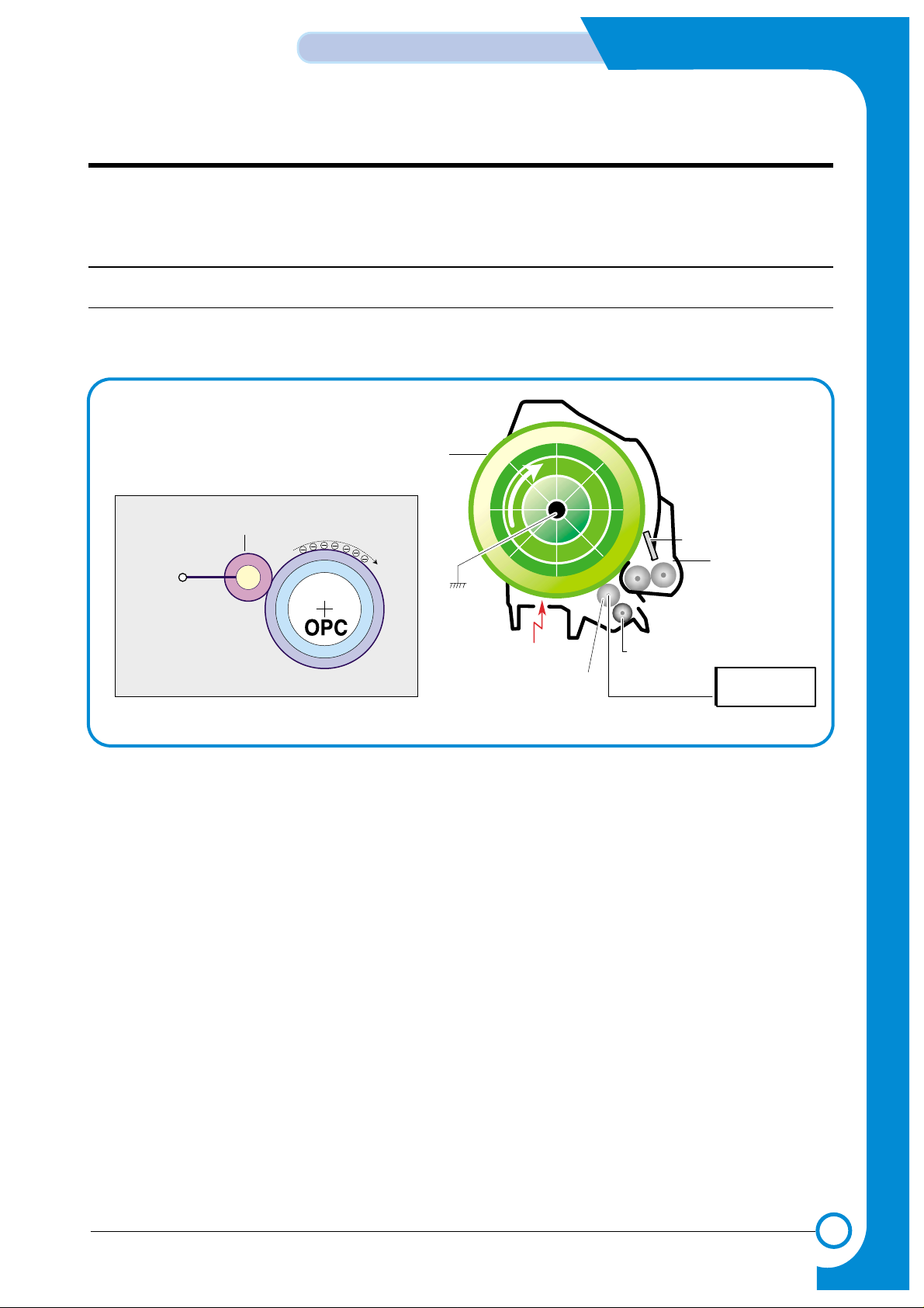
5.1.1 OPC Drum Unit (Charge Section)
The OPC Unit is the image formation unit and it consists of the OPC drum, waster toner assembly, charge
roller assembly, etc. (see diagram below).
LSU
Charge Bias
Waste Toner Tank
Cleaning Roller
Cleaning Blade
Charge Roller
OPC Drum
-1000V ~ -1500V
Charge Roller
HVPS
1) Structure
* OPC drum: The laser light coming from the LSU forms an latent electric image on the surface of
the OPC drum.
* Cleaning Blade: Removes remaining unwanted toner from the OPC drum.
* Waste toner tank: Collects and stores the waste toner.
* Charge roller: The charge roller is charged to a negative high voltage (-1KV~1.5KV) It is in con-
tact with the OPC drum and produces a uniform (-) voltage on its surface of approximately -500~-
800V.
2) Type
* Life span: 50K Images (Color 12.5K)
* Waste toner removal: Transferred to a user replaceable tank
* Waste tank sensors: LED type, detects tank present and tank full
* OPC drum diameter: 120mm
* Power: Main motor (BLDC)
* Charging method: Charge roller
* Eraser method: LED lamp (+5V/2Pin)
* PTL: LED lamp (+5V/2Pin)
Page 2
5-2
System Outline
Samsung Electronics
Service Manual
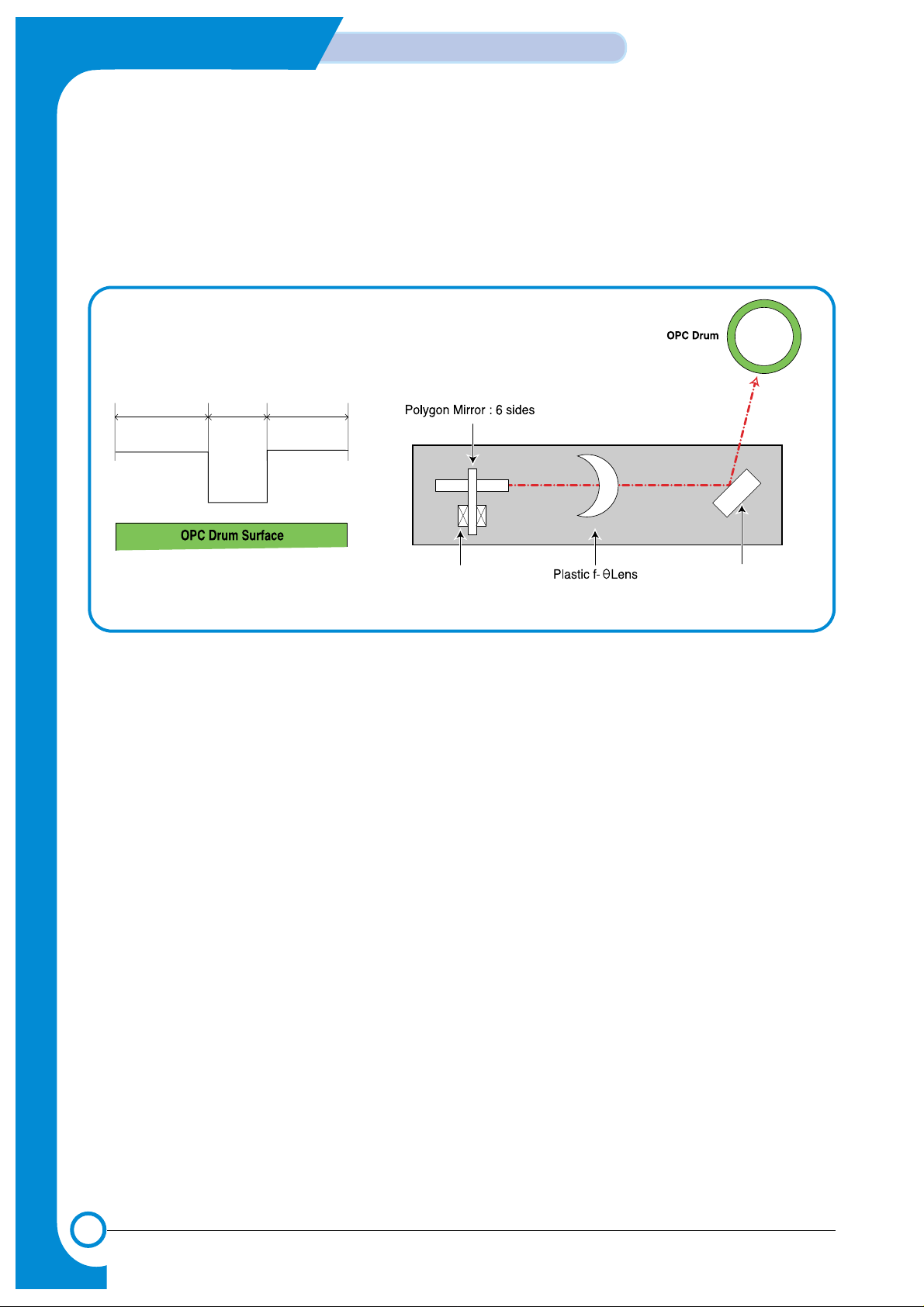
5.1.2 LSU (Exposure)
The bitmap image data stream is used to switch the LSU data beam. Where white paper is
required the beam is off, where ink is required the beam is turned on. When the laser is on
and the beam strikes the OPC drum surface the charge is reduced to -50V, where the beam is
switched off the charge on the OPC surface remains at -600V. In consequence a latent image is
formed on the drum surface.
-600V -600V
-50V
Reflecting MirrorPolygon Motor
(30,000rpm)
Unexposed Expesed Unexposed
Page 3
5-3
Samsung Electronics
System Outline
Service Manual
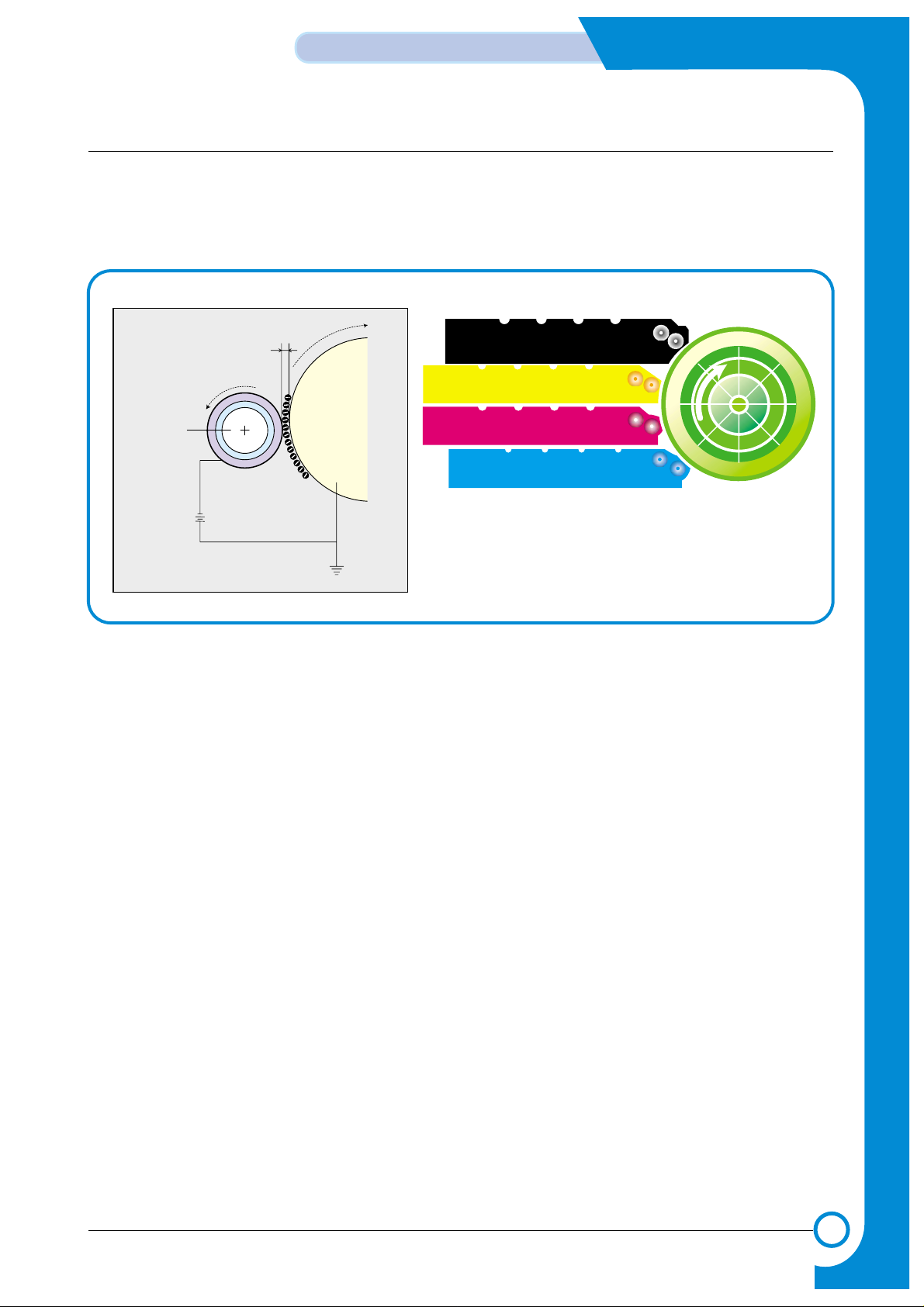
5.1.3 Toner Cartridge (Development Section)
In the development stage toner particles are transferred from the toner cartridge onto the surface
of the OPC drum. The OPC drum and the developer roller rotate in opposite directions. Toner on
the developer roller is charged to the developing voltage (-370V ± 3%). Toner is attracted to the
OPC drum in those areas where the OPC drum surface charge is -50V. Toner is not attracted to
those areas of the surface carrying a -600V charge.
1) Type
* Developing method: Non-magnetic, Mono-component developing system.
* Toner cartridge order: K, Y, M, C from top.
* Developing sequence: Y, M, C, K
* Life span: 7K(K) / 5K(C, M, Y)
* Power: DEVE motor (BLDC)
* Power transmission: Electric clutch
* Dot counting method
DEV . - Black
DEV . - Yellow
DEV . - Magenta
DEV . - Cyan
DEV . - Black
DEV . - Yellow
OPC
DEV . - Magenta
DEV . - Cyan
OPC
Drum
OPC
Dev Roller
Developing
Voltage
Dev Gap
Page 4
5-4
System Outline
Samsung Electronics
Service Manual
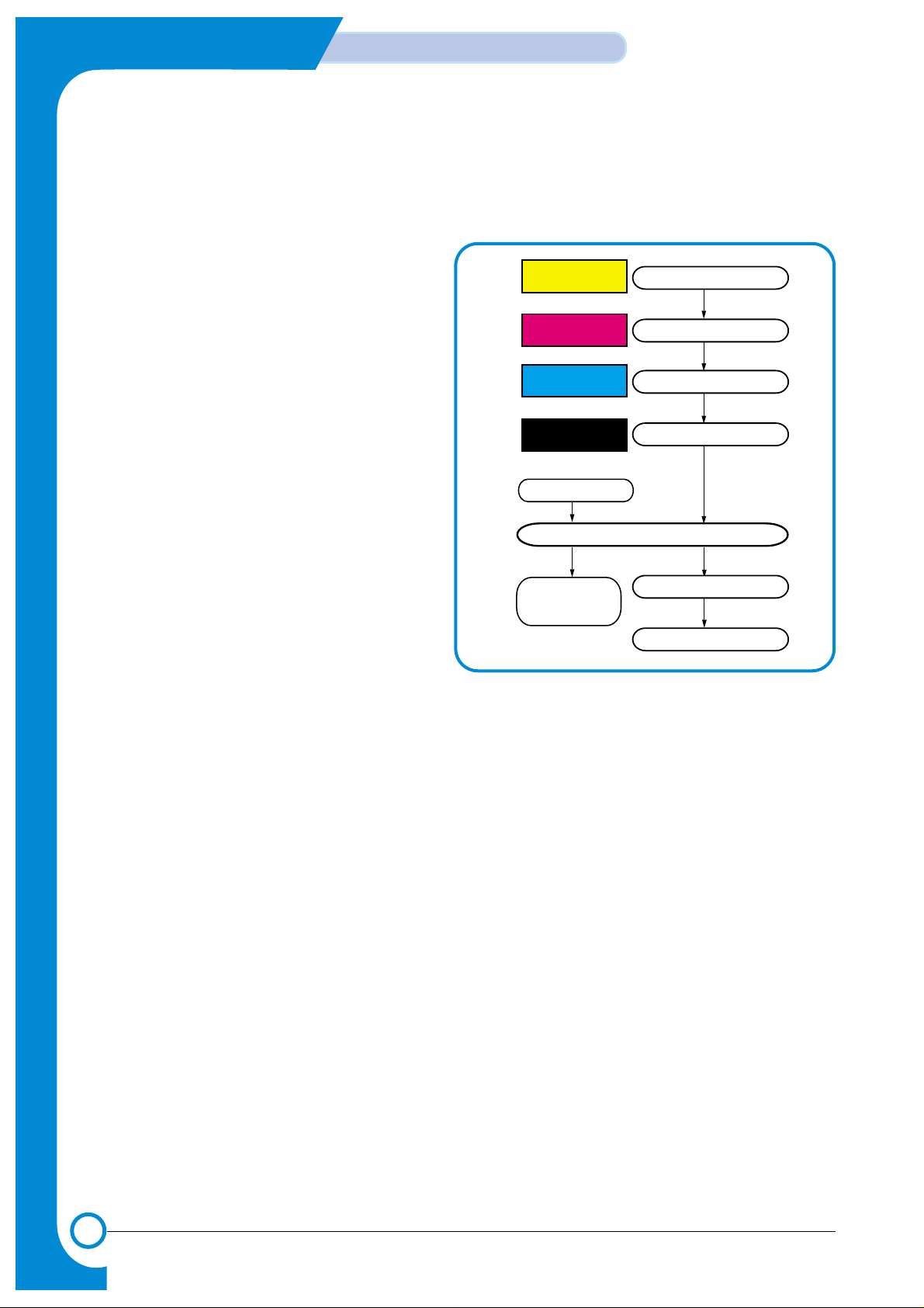
2) Developing state of color
The page image is built up from each of the 4 colors and transferred to the paper as described below.
> Developing sequence: Y, M, C, and K
1) A latent image containing only yellow toner is
created on the OPC drum and then transferred
onto the ITB.
2) A latent image containing only magenta toner
is created on the OPC drum and then transferred onto the ITB to add to the yellow image
already in the ITB.
3) A latent image containing only cyan toner is
created on the OPC drum and then transferred
onto the ITB, adding to the 2 colors already
present on the ITB
4) A latent image containing only black toner is
created on the OPC drum and then transferred
onto the ITB, creating an image on the ITB
consisting of the 4 colors.
5) The Image on the ITB is secondly transferred
onto paper using the T2 transfer roller.
6) The image on the page is then fused and the
paper is ejected into the output tray.
3) Toner cartridge empty detection
Software Dot count.
Developing and Image Transfer
Developing and Image Transfer
Developing and Image Transfer
Paper Take-up
Fusing
Cleaning of
Image Transfer Belt
Paper Exit
Image Transfer to page
Developing and Image Transfer
Yellow ColorYellow Color
Magenta ColorMagenta Color
Cyan ColorCyan Color
Blacl BolorBlack Color
Page 5
5-5
Samsung Electronics
System Outline
Service Manual
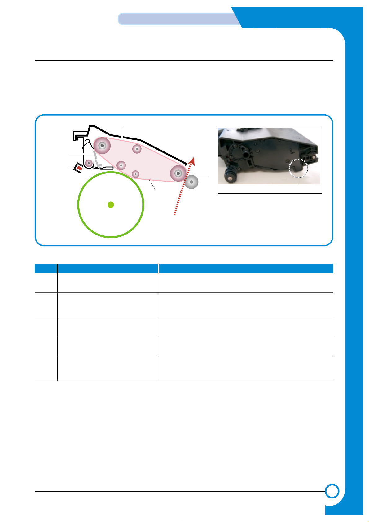
5.1.4 Image Transfer Section
The toner image formed on the OPC drum is transferred to the ITB (Image Transfer Belt), this is called the
primary image transfer. When the final image has been built on the ITB it is transferred onto paper, this is
called the secondary image transfer.
1) Structure
DUPLEX
OPC DRUM
1
2
3
5
4
Paper Path
NO. Name Description
1. Image Transfer Belt Used to build up the 4 color image from the OPC drum.
Colors are transferred in the order Y, M, C, K
2. Image Transfer Belt cleaner After the final image is transferred onto paper any waste
toner is removed from the transfer belt using this cleaning
blade
3. PTL (Pre-Transfer Lamp) Reduce the electric potential of OPC Drum surface before
primary image transfer the image on the OPC Drum.
4. Image Transfer Roller (T2 Roller) This transfers the final toner image on the image transfer belt
to paper.
5. ITB Home Sensor This sensor is used to ensure that each of the 4 color
images starts at exactly the same point on the ITB. It works
by detecting a fixed point on the belt.
ITB Home Sensor
Page 6
5-6
System Outline
Samsung Electronics
Service Manual
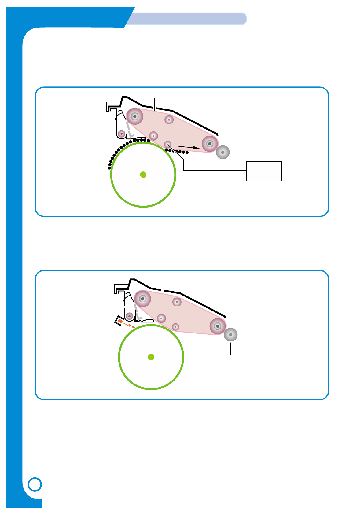
2) Primary Image Transfer
A colored page is split into 4 component color parts and developed one color at a time in turn on
the OPC (in the order Y, M, C, K). The final image is built up on the ITB by transferring these separate color images from the OPC drum.
DUPLEX
OPC DRUM
Primary Image Transfer Bias
Image Transfer Belt
Image Transfer Roller
HVPS
3) PTL (Pre-Transfer Lamp)
It is arrayed LED on PCB Board. Main function is improving the T1 utility factor by reducing the
adhesive strength of OPC and Toner by irradiation on the OPC Drum formatted the image.
DUPLEX
OPC DRUM
(LED)
PTL
Image Transfer Belt
Image Transfer Roller
Page 7
5-7
Samsung Electronics
System Outline
Service Manual
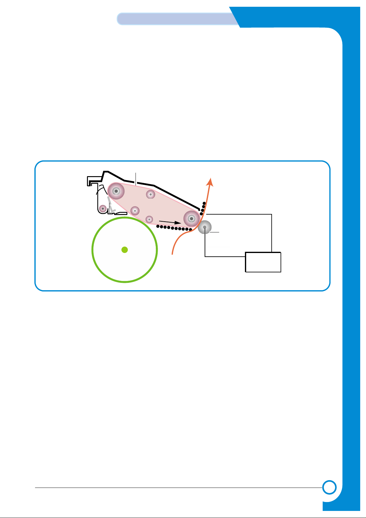
4) Secondary Image Transfer
The image is built up on the ITB (primary image transfer). This image is then transferred onto paper
using the T2 transfer roller (roller transfer system) this process is known as the secondary image
transfer.
* The HVPS applies the Image Transfer Bias voltage to the Image Transfer Roller (T2), this
transfers the image from the belt onto the paper.
* When the image is to be transferred from the ITB to the paper the image transfer roller
pressure contact solenoid is activated and this activates a cam which moves the T2 roller
into contact with the belt.
*After the transfer has taken place any remaining charge on the paper is removed by
applying a charge removal bias (generated in the HVPS) to a charge removal plate
>T ype
* Transfer method: Semi-conductive roller contact method
* Effective transferring range: 218mm (i.e. maximum image length)
OPC DRUM
Paper
Image Transfer Bias
Charge Removal Bias
Image Transfer Belt
Image Transfer Roller
HVPS
Page 8
5-8
System Outline
Samsung Electronics
Service Manual
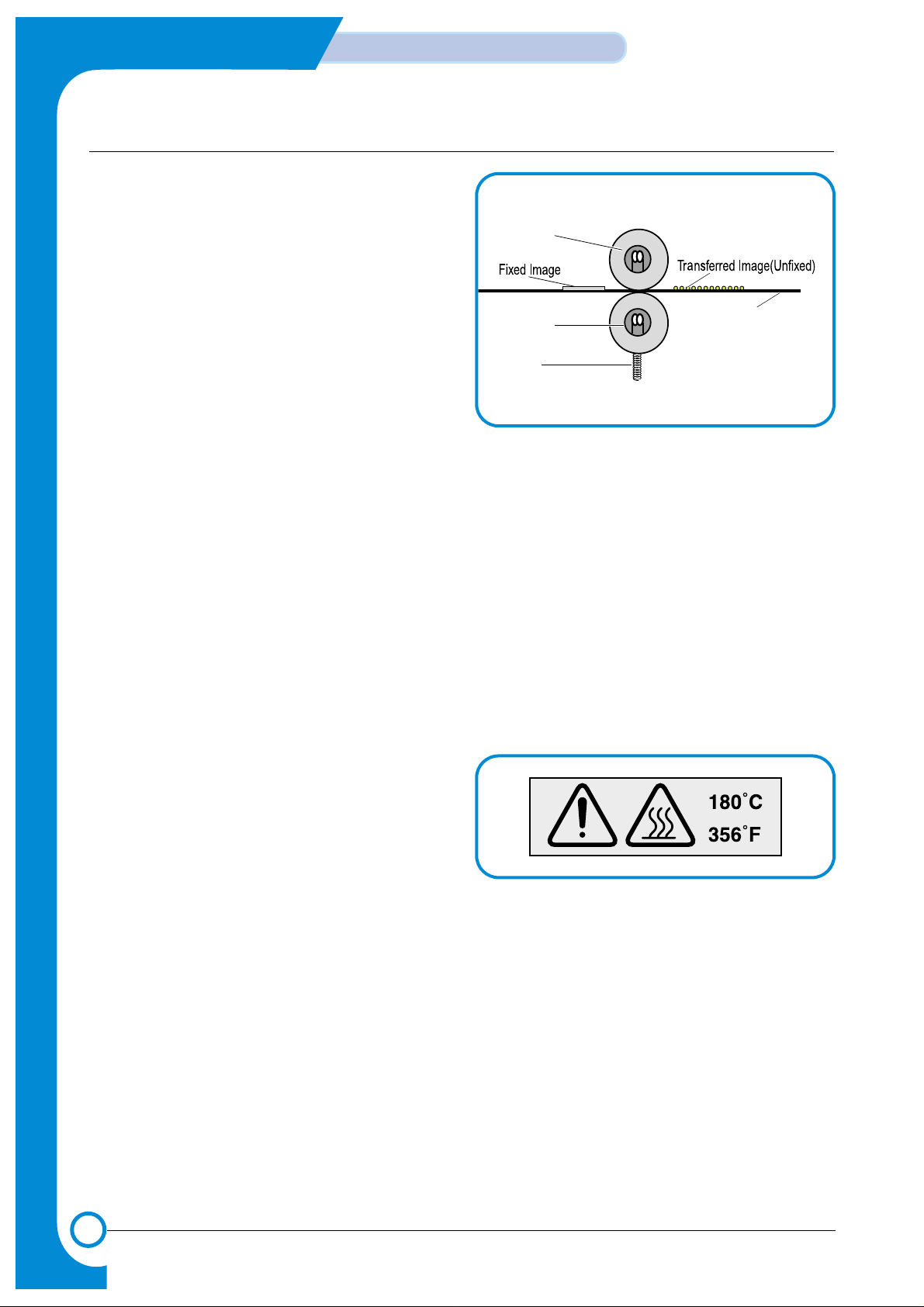
5.1.5 Fuser (Fusing Section)
Toner that has been through the primary and
secondary image transfer processes is fixed,
semi-permanently, to the paper.
The fuser unit consists of heat lamps (2 ea), heat
rollers (2 ea), thermistor, and thermostats (2 ea). It
melts the toner onto the paper using pressure and
high temperature to complete the printing process.
1) Thermostat (2pieces)
If the heat lamps or heat rollers overheat the
thermostat turns off power to the lamps in the
fuser unit to prevent fire. It is a temperature
cut-off device.
2) Thermistor
The thermistor detects the temperature of the heat roller's surface, and feedbacks the information
to the main processor which uses this information to control power to the fuser lamps in order to
maintain the heat roller at a steady temperature.
3) Heat Roller (2pieces)
Halogen lamps are used to heat the heat rollers. The heat rollers have a special Teflon surface
which ensures that any melted toner which comes into contact with the heat roller surface does not
stick. Paper passes between the two rollers which evenly heat the paper from both sides to melt
the toner and semi-permanently fix it to the paper.
4) Safety Information
> Overheat protection
* 1st level protection: Print engine is stopped if overheat is detected
* 2nd level protection: Software turns off lamp power if overheat is detected.
* 3rd level protection: Thermostat turns off lamp power if overheat is detected.
> Protecting device
* Fuser unit power is turned off when
the duplex cover or the toner
cartridge door is open.
* This machine keeps the surface
temperature of the fuser unit cover
under 80°C, and it has a caution
label attached inside the exit cover
where it can be easily seen by the user.
Heat Roller
Heat Roller
Heat Lamp
(500W)
Heat Lamp
(300W)
Paper
Spring
Page 9
5-9
Samsung Electronics
System Outline
Service Manual
5.1.6 Exit
After passing through the fuser paper is ejected into the paper exit tray. Any static electrical charge
is removed by static discharge brushes.
When operating in duplex print mode, after printing the front side of the page, the paper exit roller
reverses to feed the paper back into the machine in order to print the second side of the page.
5.1.7 Waste Toner Collection Process
Waste toner on the OPC drum and on the image transfer belt is collected into the waste toner tank.
* After transferring the toner image on the OPC drum to the ITB, a cleaning blade scrapes waste
toner from the OPC drum, and the waste toner is collected into a waste toner tank.
* An Image Transfer Belt cleaner scrapes waste toner from the image transfer belt, and the waste
toner is collected into a waste toner tank.
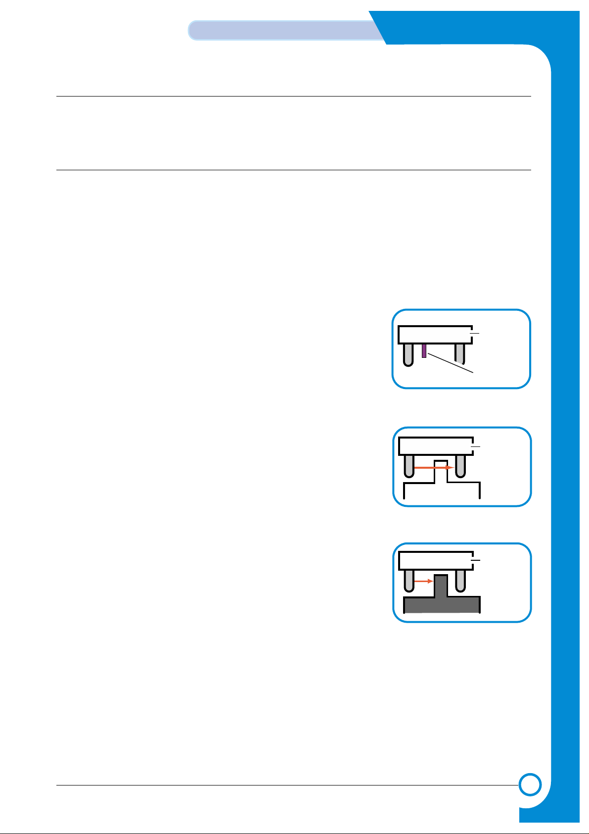
1) Waste toner tank sensor
A waste toner sensor detects the presence of the waste toner tank and also detects if the tank is full.
This is an On / Off detection. Do not operate the printer without a waste toner tank.
> No waste toner tank
When the waste toner tank is not installed the waste toner senor
actuator blocks light from the senor LED.
> A little waste toner
When the sensor LED light reaches the photo sensor passing
through the waste toner tank this indicates that the tank is not full.
> Waste toner tank full
When the waste toner tank is full to the level of the waste toner
sensor, the senor LED light is blocked by waste toner indicating
that the tank is full.
Waste Toner Sensor Actuator
Waste Toner Sensor
Waste Toner T ank
Waste Toner Sensor
Waste Toner TankWaste Toner T ank
Waste Toner Sensor
Page 10

5-10
System Outline
Samsung Electronics
Service Manual
5.2 Outline of Engine Firmware
The CLP 510/510N use 4 different colored toners (Yellow, Magenta, Cyan, Black) and it is a laser color
printer. Engine firmware controls the print processes, driving the print engine, paper feed, developer, fuser,
and paper discharge systems. It has both color and mono printing modes. The printer process sequence is
as follows:
System Initialization
When power to the system is turned on all system values are
initialized
Print Printer performs the actual printing job.
Post-Print
The finishing state of printing job. The printer puts all systems back
into a state ready to start the next job and then enters the Ready state.
Warm-Up Each part of system is activated and the system automatically
checks its status and all systems are prepared to accept a job for printing.
Pre-Print As soon as a printing order is inputted from host, the printer checks
the status of each part before performing the printing job.
Ready The normal state of the printer, waiting to receive a command from
a host to start a job. After a predefined length of time in the Ready
state if no print jobs are received the Power Save mode is entered.
Page 11

5-11
Samsung Electronics
System Outline
Service Manual
5.2.1 System Initialization
The system initialization process is carried out immediately after power on. The following tasks are performed.
1) Initialize ASIC
2) Initialize system variables
3) Initialize a virtual timer
4) Initialize fuser control
5) Initialize ADC
6) Set-up ITB HOME interrupt
5.2.2 Warm-Up
In the warm-up stage, the following tasks are performed.
1) Self Test
* System error check
* Cover open check
* Device (ITB, OPC, DEVE cartridge) check
* Heating error check
* Motion of motor and jam & paper empty check
* Check Feed and exit sensors. If paper is detected it is ejected. If the paper detection does not
clear a jam recovery is carried out and the paper drive unit is instructed to drive for the maximum
permitted paper length.
2) Heat Control
The heater control unit separately manages the temperature of the heat lamps.
* Target temperature (165°C)
* Temperature below 130°C - heat unit fully on,
* Temperature above 135°C temperature is controlled by reading the temperature value
every 10msec.
3) Cleaning
Transfer rollers, OPC and ITB are electrically and mechanically cleaned.
Page 12

5-12
System Outline
Samsung Electronics
Service Manual
5.2.3 Ready
1) Host interface is monitored for print commands
2) Heat control
* Target temperature (165°C)
* Every 40 seconds, temperature value for the previous 250ms is read and a proportional control
process is carried out
3) This is the standby mode entered after warm-up or after completing a print job.
4) System Error check
5) Power save state is entered after timeout
> Wakeup condition
* When a "wakeup" order is received
* When a cover is opened and then closed
* When the level of the paper empty sensor changes.
> Heat lamp is off
5.2.4 Pre-Print
This is the preparation stage before processing a printing job and after receiving a print command from a host.
1) Start LSU
* Run Scanning motor
* Check motor ready
* Turn LD on
2) Start BLDC motor, Eraser/PTL on
* Run main motor
* Check lock signal
* Run developer roll motor
* Check lock signal
3)Turn High Voltage On
* Charger on
* Developer high voltage off
4) Cleaning
* OPC cleaning (Mechanical motion)
* ITB cleaning
5) Jam check
6) Motor Unlock Check
7) Check and Set a High Voltage Condition (T1, T2, Charger)
8) Initialize Printing Parameters
* Paper size, copies, cassette ...
* Image pixels, image times, y-offset, x-offset
* Flags
9) Check Print mode
* Color print mode:
- Except legal & OHP/Legal/OHP
- Simplex/Duplex
* Mono pint mode: Simplex/Duplex/OHP
Page 13

5-13
Samsung Electronics
System Outline
Service Manual
5.2.5 Print
After sensing the ITB home position the following tasks are performed,
Send Psync signal to controller -> Operates virtual timer for each color(Vdata) -> Forms latent
image on OPC drum -> Supplies toner on OPC drum -> Transfers image to ITB (T1 ) -> Pickups a
paper -> Transfers image to a paper (T2)
1)Check ITB Home (Treated by Home interrupt): It is designed to detect ITB HOME every 3 seconds.
a) ITB Home sensing
b) If a test mode is set up, a test pattern is printed.
c) Acounter value is set up that addresses the timing to turn on page sync.
d) The virtual timer for each color (Y, M, C, and K) is set up
e) If Home is not detected every 3 seconds, an error is reported.
2)Paper path and print
a) Printing paper from cassette, MPT and SCT is picked up
b) Control paper path
* Stop when the leading edge of a piece of paper reaches the feed sensor.
* If the leading edge doesn't reach the feed sensor, it is an error.
* While transferring the last color to the ITB, re-feed the paper.
* Checks if the paper reaches the exit sensor in certain time. If it reaches too soon, or it doesn't
reach, it is an error.
* Checks that the paper passes the exit sensor or not.
c) Jam check
* Check reaching time and passing time for the paper reaching and passing the feed and exit
sensors. If time exceeds a certain time, it is an error.
d) Duplex control
* After passing the exit sensor, the duplex clutch is operated to mechanically change the direction
of the paper flow in order to print the other side.
e) Printing sequence and motion for each color
* Use a virtual timer for printing the colors in sequence. (Yellow, Magenta, Cyan, Black)
> What is a Virtual Timer?
A virtual timer is a mathematical function for creating regular action at fixed time intervals. The standard setting is for a 5msc timer interrupt.
5.2.6 Post-Print
This is the last stage of the printing process. Its functions are described below.
a) Clean transfer rollers
b) Stop all virtual timers
c) Initialize parameters used in the printing process.
d) Stop motors
Page 14

5-14
System Outline
Samsung Electronics
Service Manual
MEMO
 Loading...