

Page 1
4
4
4-1
Samsung Electronics
Summary of product
Service Manual
4. Summary of Product
This chapter describes the functions and operating principles of the main components.
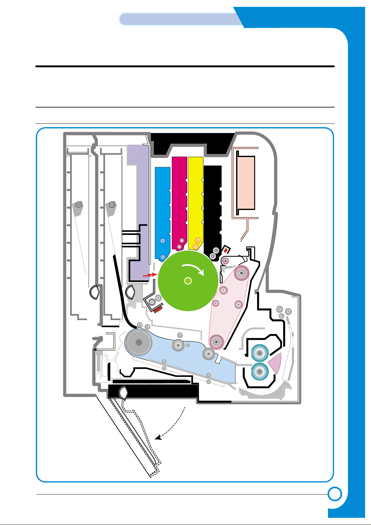
4.1 System Structure
4.1.1 Main Parts of System
HVPS
Eraser LampEraser Lamp
HVPS
DEV. - Black
DEV. - Yellow
OPC
Pick-up
Roller
DEV. - Magenta
DEV. - Cyan
CASSETTE
LSU
ITB Unit
Feeder
DUPLEX
T2 Roller
Fuser Unit
EXIT Unit
MPF Path
MPFMPT
DEV. - Black
DEV. - Yellow
OPC
Pick-up
Roller
DEV. - Magenta
DEV. - Cyan
SCF
SCT
FCT
LSU
Deve CoverDeve Cover
ITB Unit
Feeder
DUPLEX
T2 Roller
Fuser Unit
EXIT Unit
PTL
PTL
SCF Path
Pick-up
Roller
Pick-up
Roller
Pick-up
Roller
Pick-up
Roller
Page 2
4-2
Summary of Product
Samsung Electronics
Service Manual
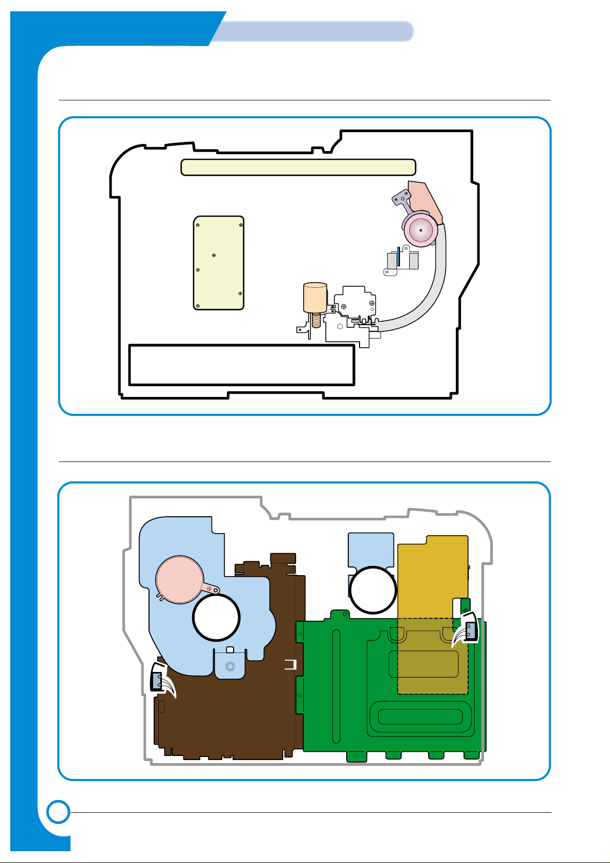
>> Front View
Deve OEM
PBA
Panel PBA
Waster Toner Sensor
Waster Toner Motor
SMPSSMPS
Main DriveMain Drive
Fan Fan
Deve DriveDeve Drive
Deve Drive PBADeve Drive PBA
Duplex Cover
Open S/W
Duplex Cover
Open S/W
Deve Cover
Open S/W
Deve Cover
Open S/W
Main Conrtoller PBAMain Conrtoller PBA
>> Rear View
Page 3

4-3
Samsung Electronics
Summary of product
Service Manual
1) OPC Unit
Images are created on the OPC unit using an electro-photographic process. The unit consists of:* OPC Drum
* Waste Toner Ass'y used to collect waste toner remaining on the OPC drum,
* Charge Roller Assy
2) ITB Unit
ITB stands for Image Transfer Belt. An image developed on the OPC Drum is transferred first to the
ITB. This is called the T1 Transfer (Primary Image Transfer).
Images are built up in layers on the ITB.
First the Yellow (Y) colour image is created on the OPC and transferred to the ITB
Next the Magenta (M) colour image is created on the OPC and transferred to the ITB
Followed by the Cyan (C) and Black (K) images.
3) Transfer Roller
Once the complete, full colour, image, has been built up on the ITB the Transfer Roller is used to
transfer the image onto paper. This is called the T2 Transfer (Secondary Image Transfer)
4) FCT (First Cassette Tray)
It stores and automatically feeds print paper.
Pick-up Roller picks up paper, controls drive, feeds paper, removes static electricity, and so on.
> Spec.
* Paper arrange way : Side Registration
* Paper Direction : FISO (Front-in, Side-Out)
* Cassette Type : A4, Ltr
* Paper Discharge : Separation Claw
* Capacity : 250 Sheets (Standard paper 75mg/m? 20lb)
* Paper Size : A4, Letter
* Paper Weight (average) : 60~90g/m2(16~24lbs)
* Paper Type : General Printing Paper
* Additional Function : Paper Empty Sensor
5) SCT (Second Cassette Tray)
This additionally stores and automatically feeds printing paper. Its function is the same as the FCT
(First Cassette Tray)
> Spec.
* Paper arrangement : Side Registration
* Paper Direction : FISO (Front-in, Side-Out)
* Cassette Type : A4, Ltr
* Paper Discharge : Separation Claw
* Capacity : 500 Sheets (Standard paper 75mg/m220lb)
* Paper Size : A4, Letter
* Paper Weight (average) : 60~90g/m2(16~24lbs)
* Paper Type : General Printing Paper
* Additional Function : Paper Empty Sensor
Page 4

4-4
Summary of Product
Samsung Electronics
Service Manual
6) MPT (Multi Purpose Tray)
The Multi-Purpose Tray not only feeds general printing paper but is also used for many other kinds
of paper such as those paper sizes not supported by the cassette, envelopes, OHP, etc.
> Spec.
* Capacity : Cut Sheet : 100 Sheets (Standard paper 75mg/m220lb)
* OHP : 300 Sheets
* Envelope & Label & Card Stock : 10 Sheets
* Paper Arrangement : Side Registration
* Power : Main Motor (BLDC)
* Driving Management : Solenoid
* Paper Discharge : Friction Pad Method
* Paper Size : Legal, Folio, A4, Letter, Executive, JIS B5, A5, A6
* Paper Weight (Average) : 60~163g/m
2
* Paper Type : General, Label, Post Card, Transparency, Envelope, Card Stock (Tracing
Paper is not served)
* Additional Function : Paper Empty Sensor
7) Feeder
* Paper Arrangement : Side Registration.
* Power : Main Motor (BLDC)
* Paper Management : Solenoid
8) Duplex Unit
The Duplex Unit is used to reverse feed paper when printing on the second side (known as Double
sided or Duplex printing). The Duplex Unit is not an optional extra, it is built-in at manufacturing
time and is integral with the Transfer Roller.
> Spec.
* Power : Main Motor (BLDC)
* Paper Reverse Function: After the front side of the original document is printed, it is transferred
to the duplex unit in order to print the reverse side of original document. The motor drives
the exit roller in the reverse direction to feed the paper back into the machine.
9) Exit Unit
The Exit Unit guides paper that is just about to leave the print engine. Printed-paper is discharged
by the Exit Roller and Kicker into the Output Tray.
> Spec.
* Capacity : 250 sheets (Standard A4, 75g/m2)
* Paper Direction : Face Down
* Exit Drive Roller : It is driven by Main Motor (BLDC), and it rotates clockwise for normal
feed and antic-clockwise when reverse feeding for duplex printing.
* Bin Full Sensor : There is no Bin Full sensor fitted on this model.
10) Toner Cartridge
There are four toner cartridges, each containing a different colour ink : C (Cyan), M (Magenta), Y
(Yellow) , and K (Black).
Each one of these toner cartridge is independent and can be changed independently.
11) Fuser Unit
This unit consists of 2 Heat Lamps, 2 Heat Rollers, 2 Thermostats and a Thermister. It melts and
fuses the toner, transferred by the transfer roller onto the paper, by applying pressure and high
temperature to complete printing job.
12) LSU
This is a core part of LBP. It forms a latent image on the surface of OPC drum using a static
charge.
* Resolution: Real 600 dpi
Page 5

4-5
Samsung Electronics
Summary of product
Service Manual
13) Main Drive Unit
This motor drives, by way of a gearbox, the OPC unit, ITB unit, feeder unit, fuser unit, exit unit and
duplex unit.
> Spec.
* Power : 20W Max (24V)
* Drives : OPC unit, ITB unit, Fuser, Feeder, Duplex unit, Exit unit
14) DEVE Drive Unit
This motor drives, by way of a gearbox, the toner cartridges and ITB cleaning cam.
> Spec.
* Power : 20W Max (24V)
* Drives : DEV (4 Color)/ITB Cleaning)
15) SMPS (Switching Mode Power Supply)
This power supply uses the AC supply voltage to generate the DC voltages used by the system.
The SMPS has 4 output channels (+3.3V, +5V, +24V, +24VF).
The AC Heater Control Unit that supplies power to the fuser is also located on the SMPS.
16) HVPS (High Voltage Power Supply)
The HVPS creates the high voltages (Charger, Supply, T1, T2, Developer) used for the electro
photographic process. The high voltage is created from the 24V line from the SMPS. High Voltage
output is supplied to the toner cartridge, OPC drum unit, ITB unit, and Transfer roller.
17) Main Controller PBA
The Main controller PBA is very important as it is the heart of printer. It has several major function
blocks.
* CPU and SPGPm Block: This manages the printing order from the host, creates bitmap data for
the engine to print and controls various devices that are needed to operate the printer.
*Engine Control Block: This manages images and controls various kinds of I/O
* Memory Block : The operating system uses this to store video data and printing orders given by host.
* ROM Block : The printer OS and PDL Interpreter are stored here.
* In addition there are USB 2.0 Block, IEEE 1284 Block, Option Block, OPE Panel, etc.
18) DEVE Drive PBA
Each toner cartridge requires the HV Supply only when that colour image is being processed. This
unit takes its HV source from the HVPS and using 4 solenoids selects which cartridge is to receive
the Supply voltage. This section also contains the DEVE motor, DEVE clutch, and DEVE solenoid
drives. These are activated in sequence as required by the printing process.
19) DEVE OEM PBA
This detects new or used toner cartridges and also checks that cartridges are approved parts. If a
toner cartridge is not suitable for the machine an error message is displayed.
20) Waste Toner Ass’y
A cleaner blade on the OPC unit cleans waste toner from the OPC drum after every image is
transferred to the ITB. Once the complete image is transferred from the ITB onto paper the ITB
Cleaning Solenoid activates and a cleaning blade removes waste toner from the ITB. Waste toner
is transferred to the waste toner tank.
The error message "Waste Toner Tank Full/ Not Install" is indicated on the LCD Panel. Replace the
Waste Toner Tank immediately or the printer may be damaged
Page 6
4-6
Summary of Product
Samsung Electronics
Service Manual
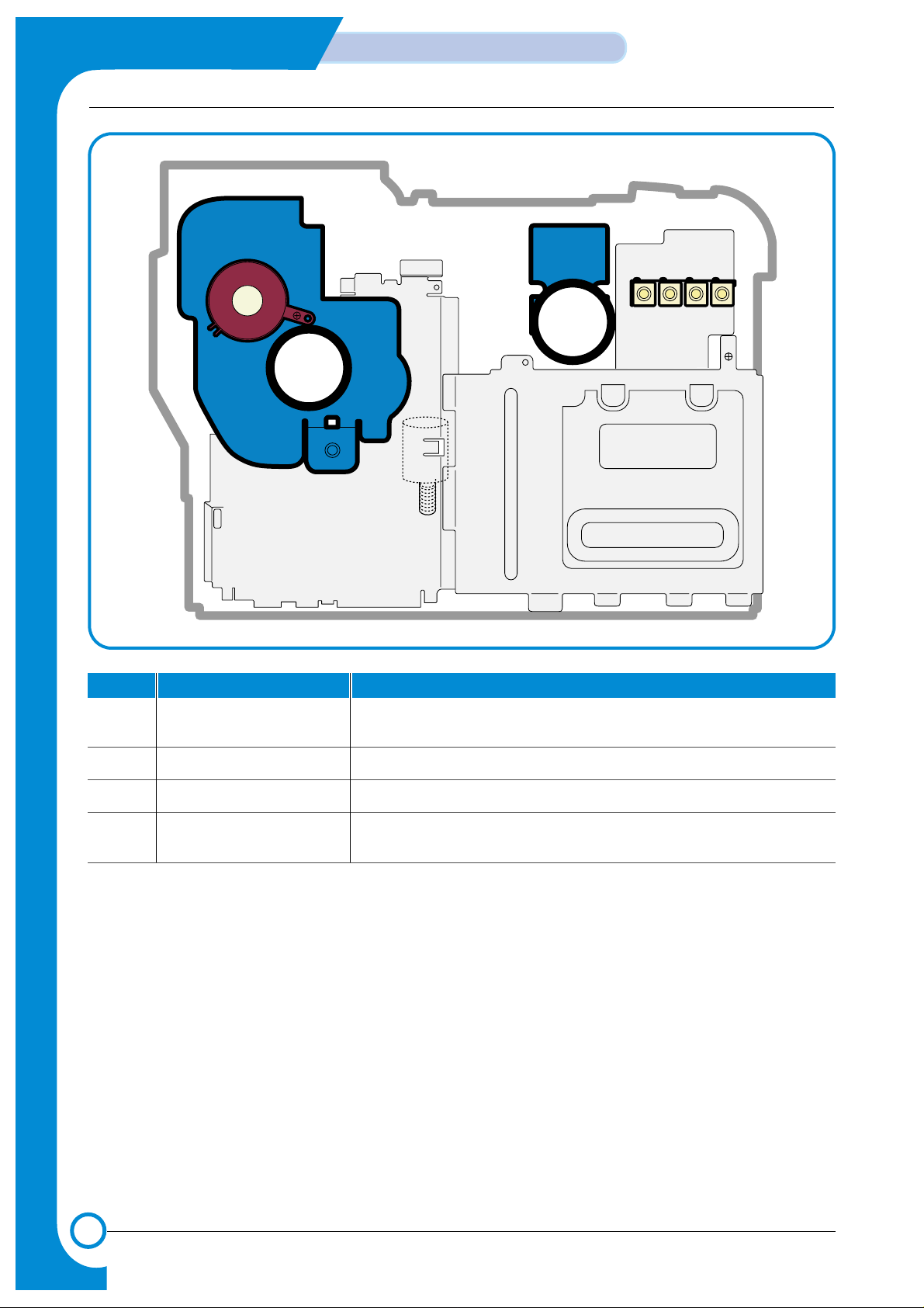
4.1.2 Motor & Fan Layout
Fan
1. Main Motor
2. DEVE Motor
4. Waste Toner Motor
Fan
1. Main Motor
2. DEVE Motor
4. Waste Toner Motor
NO. Name Description
1 Main Motor Drives the OPC unit, ITB unit, feeder unit, fuser unit, exit unit and
duplex unit.
2. DEVE Motor Drives C, M, Y and K toner cartridges and ITB cleaning cam.
3. Fan Forces cold air into the printer and takes out heat from the fuser.
4. Waste Toner Motor Transfers collected waste toner from the OPC drum and ITB to the
waste toner tank. (Refer to front view picture on 4-2 page)
Page 7

4-7
Samsung Electronics
Summary of product
Service Manual
14.1.3 Clutch & Solenoid Layout
>>Solenoid
Cartridge Solenoid(C, M, Y, K)
Duplex Solenoid
ITB Cleaning
Solenoid
Black Deve
Clutch
Black Deve
Clutch
Yellow Deve Clutch
Magenta Deve Clutch
Cyan Deve Clutch
Cartridge Solenoid(C, K, Y, M)
Yellow Deve Clutch
Magenta Deve Clutch
Cyan Deve Clutch
T2 Home SolenoidT2 Home Solenoid
MP Pick_up
Solenoid
MP Pick_up
Solenoid
Feed Regi
Clutch
Pick_up Solenoid
NO. Name Description
1. C DEVE solenoid Controls the High Voltage supply to the cyan cartridge.
2. K DEVE solenoid Controls the High Voltage supply to the black cartridge.
3. Y DEVE solenoid Controls the High Voltage supply to the yellow cartridge..
4. M DEVE solenoid Controls the High Voltage supply to the magenta cartridge.
5. Pick-up solenoid Controls the pick-up roller drive.
6. MP Pick-up solenoid Controls the MP pick-up roller drive.
7. Duplex solenoid When operating in duplex print mode, this reverses the direction
of paper feeding to feed paper into the duplex unit.
8. T2 Home solenoid This forces the transfer roller into contact with the ITB unit.
9. ITB cleaning solenoid This brings the cleaning blade into contact with the ITB unit
Page 8

4-8
Summary of Product
Samsung Electronics
Service Manual
>>Clutch
NO. Name Description
1. Yellow DEVE clutch Controls Yellow color toner cartridge drive
2. Magenta DEVE clutch Controls Magenta color toner cartridge drive
3. Cyan DEVE clutch Controls Cyan color toner cartridge drive
4. Black DEVE clutch Controls Black color toner cartridge drive
5. Feed Regi. Clutch Controls the location of picked-up paper
4.1.4 Sensor & Micro S/W Layout
NO. Name Description
1. Paper Empty Sensor(FCT) This sensor detects paper in the first (main) cassette.
2. Paper Empty Sensor(SCT) This sensor detects paper in the second (optional) cassette.
3. Paper Empty Sensor(MPT) This sensor detects paper in the multi-purpose tray.
4. Feed Sensor This sensor must operate within a certain time after paper pick-
up otherwise a JAM is detected
5. ITB Home Sensor This detects the position of the image transfer belt, and in
dicates the start location for image writing. It is used to ensure
that all 4 colour images are correctly registered.
6. Waste Toner Sensor This detects whether the waste toner tank is mounted or not and
the amount of waste toner in the tank.
7. Exit Sensor This detects whether printing paper is discharged or not.
8. DEVE Cover Open S/W This detects the open/closed status of the DEVE Cover.
9. Duplex Cover Open S/W This detects the open/closed status of the Duplex Cover.
Note: * ITB Home Sensor is located in the ITB unit. If it develops a fault replace the ITB unit.
* Please, refer to the Chap. 7 Arrangement and Adjustment, "Paper Path diagram", for the location
of the paper empty sensor, feed sensor, and exit sensor.
* Please, refer to page 4-2 for the location of the waste toner sensor, DEVE cover open S/W, and
duplex cover open S/W.
Page 9

4-9
Samsung Electronics
Summary of product
Service Manual
4.1.5 Main Controller PBA
USB
CN24
CN27
CN28
CN29
CN30
CN31
CN32
CN33
DUPLEX
CN26
T2 HOME
BLDC1
TH1
FUSER_FAN
SMPS
MP_EMPT
MP SOL
FEED
CN25
PICK_UP
CN23
CLT_FEED
CN21
EMPT
CN1
CN16
SCF
CN12
LSU
CN6
OPC KEY
CN5
DEVE_DRIVERDEVE_DRIVER
CN14
LSU SW
CN17
WASTE TONER & EXIT
CN15
TH3
CN4
PANEL
LAN
CN7
HVPS
CN11
PTL & TH4
CN35
SOL_ITB_CLN
CN38
BLDC2
CN37
OEM_CONN
For Test
CN10
ITB
CN9
NIC
Option : NIC
Page 10

4-10
Summary of Product
Samsung Electronics
Service Manual
RAM
DIMM
SPGPm
Main Control
FLASH MEMORY
OSC2 12MHz
(Reserved)
OSC1
12MHz
LPEC1
(ENGINE CONTROL)
OSC3
23.8807368MHz
U36
(Counter Memory)
Page 11

4-11
Samsung Electronics
Summary of product
Service Manual
USB 2.0
SDRAM
64MB
EEPROM
4k bit
Flash Memory
2MB
NPC / (W-LAN)
Opti onal
Full Function
Engine
Control
Block
LPEC1
SDRAM DIMM
34MB~128MB
SPGPm
Panel
16x2 LCD
5pinUART
1) CPU BLOCK
This is the heart of the machine. A120MHz - 32bit RISC processor is used to manage commands
and data supplied by the host. This is converted into a bitmap image which is passed to the engine
block for printing. The CPU is also used to control various other devices e.g. the USB 2.0 Interface
chip.
2) SPGPm overview
* Package
- 272 pins PBGA
* Power
- 1.8V(Core), 3.3V(IO) power operation
- P1284 inputs : 5V tolerant
* Speed
- 120MHz core(ARM946ES) operation, 60MHz bus operation
- Supportable Engine Speed : under 30ppm
* Dual bus architecture for bus traffic distribution
- AMBAHigh performance Bus (AHB)
- System Bus with SDRAM
* Integrated ARM946ES
- 32-bit RISC embedded processor core
- 16KB instruction cache and 16KB data cache
- No Tightly Coupled Memory
- Memory Protection Unit & CP15 control program
Page 12

4-12
Summary of Product
Samsung Electronics
Service Manual
* Direct connection up to 4 Flash ROM banks
- Burst capability
- Programmable timing per bank
- Up to 16MB address per bank (Limited to 8MB per bank when nDREQ0 is enabled)
* Direct connection up to 6 I/O banks & 4 DMA I/O banks
- Programmable timing per bank
- Programmable recovery timing per bank for slow devices
- Up to 16MB address per bank (Limited to 8MB per bank when nDREQ0 is enabled)
* Direct connection up to 5 SDRAM arrays
- SDRAM controller supports PC-66, PC-100 and PC-133 SDRAMs running at 60MHz
- Up to 128MB per array, up to 512MB totally
- Wide support of various SDRAM configurations, including programmable band and column
address
- Programmable SDRAM refresh time interval
* 4 General Purpose DMA controllers
- Extensible architecture allows peripheral devices such as scan devices to have access to SDRAM
arrays through DMA channels
- 8bits, 16bits and 32bits Data Transfer Modes are supported
- IO to Memory, Memory to IO, Memory to Memory transfer support
* IEEE1284 compliant parallel port interface
- Compatible ECP communications are supported
- Direct support for IEEE1284 compliant data transceivers
* RSH
- Fully Hardware Rotator, Scaler and Halftoner support
- Variable Image Scaler and Image Halftoning Unit for PCL6
- Pattern & Gamma Table Memory : 1024 x 8, 256 x 8 x 4
* Graphic Execution Unit for Banding support of Printer Languages
- Support up to 256 Bit Block Transfer
- Scan Line Transfer
- Polygon Filling
- Enhanced Graphic Order
* Compression / Decompression
- CODEC : Simplified JBIG algorithm for band compression / decompression
- HCT : Halftone Compression Technology (Byte Run-Length Type)
- Independent use of both Codec, but enabling only one Codec is desirable for bus traffic
* UART
- 3 Independent Full Duplex UART channels
- Max 16 bytes FIFO to handle SIR Bit Rate Speed
- DMA support for RX and TX of Channel0
* Printer Video Controller for LBP engines
- 20MHz video rate are targeted
- Two different kinds of Printer Video Controller (Selected by Software)
- PVC : Printer Video Controller without RET Algorithm
- HPVC : Printer Video Controller with RET algorithm
(Line Memory & Lookup Table Memory : 512 x 8 , 4096 x 16)
- High performance DMA based Interface to Printer Engine
- Engine Controller
- Motor Control Unit
- Motor Speed Lookup Table Memory (128 x 16 x 2)
- Pulse Width Modulation Unit
- 4 Channels are supported
- ADC Interface Unit
- 3 ADC Channels are available
- ADC Core (ADC8MUX8) maximum clock frequency : 3 MHz
- Coversion time : 4.3us (@3MHz)
- LSU Interface Unit
Page 13

4-13
Samsung Electronics
Summary of product
Service Manual
* Timer
- 3 Independent Programmable Timers
- Watch Dog Timer for S/W Trap and Tone Generator for MFP Application
* Up to 5 External Interrupts support
- High active interrupt signals
- FIQ/IRQ Interrupt mode selectable
* Ethernet Controller (MAC)
- Full compliance with IEEE standard 802.3, 802.3u specification
- Support 10/100 Mbps data transfer rates
- DMA engine with burst modes (4 words burst and 8 words burst are supported)
* USB 2.0 interface
- USB 1.1 backward compatible
- UDC(USB Device Controller) block and USB Physical block are integrated
- Both of High Speed(480Mbps) and Full Speed(12Mbps) are supported
- 2 DMA channels support : one RX Channel and one TX Channel
- Interrupt transfer support up to 6 Endpoints
- EP0 In/Out (Control transfer), EP1 In/Out (Bulk transfer), EP2 In/Out (Bulk transfer)
* Debug support
- Only MultiICE logic support from ARM9 series
- 5 JTAG connections : TCK, TnRST, TMS, TDI, TDO
- Internal logic for synchronizing TCK and high speed CLK
- Maximum TCK frequency : 20MHz (CLK x 1/6)
Page 14

4-14
Summary of Product
Samsung Electronics
Service Manual
3) Memory Block
The operating program runs from memory (see below). It is used to store video data and printing
jobs from the host. Standard factory fitted memory is 64MB, and can be expanded using a DIMM
module mounted in the SODIMM connector. This is a user fit option, DIMMs from 64Mb - 256MB
can be used giving a total of up to 320MB of memory. DIMM modules are non standard - only
Samsung product should be used.
The memory controller is located in the SPGPm controls the SDRAM memory connected using a
32 bit 60 MHz bus.
4) ROM Block
An 8MB flash ROM is used to store the OS. The ROM controller is contained in the SPGPm
processor. When initializing after power on the contents of ROM are downloaded into memory and
the OS is run from within memory.
5) USB 2.0 Block
A Netchip Co. NET2270 is used to provide support for USB2.0 and is capable of interface speeds
up to 480Mbps. Under control of the SPGPm chip DMA is used to transfer incoming data directly
into memory.
6) IEEE 1284 Block - Korea, Russia and Asia Only
An IEEE 1284 controller is controlled directly by the SPGPm processor. ECP mode is supported.
7) Option Block
An Ethernet card can be attached using the 100 pin connector. It is connected directly to the
SPGPm processor and communicates using a 16bit bus.
8) OPE Panel
The OPE panel is controlled by a UART Block located in the SPGPm and it displays printer status
and helps the user to setup the printer. Various data is transferred using a serial interface between
a Mycom located in the OPE panel and the UART in the SPGPm.
9) Memory
There are two types of memory, program memory that uses flash and a working memory that uses
SDRAM. When printing working memory is used as band memory.
10) Sensor
Various sensors are used to detect various conditions during the printing process. These include
paper empty sensor, feed sensor, exit sensor, ITB sensor, etc.
11) Actuator Control
This section drives the various motors and clutches that are required for the paper feed and printing process. These include DEVE cartridge clutches (4 off), Feed Regi clutch, DEVE solenoids (4
off), Pick solenoids (2 off), Duplex solenoid, ITB and T2 solenoids.
12) ADC
Recognize the current of T1/T2 roll, Recognize the fixing temperature, Recognize the Waste Toner
tank, Recognize the current of Waste agitator DC Motor,Recognize the OPC/ITM key, Recognize
the Developer(Y.M.C.K) key, Recognize the set temperature.
Page 15

4-15
Samsung Electronics
Summary of product
Service Manual
4.1.6 SMPS (Switching Mode Power Supply) PBA
The SMPS unit supplies DC power for driving the whole system, it also contains an AC heater control unit
that supplies power to the fuser.
1) DC output
- Main controller PBA, OP panel, SCF, Developer driver PBA
2) AC output
-Fuser unit (Heat lamp, Thermostat)
3) Output voltage
NO Item CH1 CH2 CH3 CH4
1 Channel name +3.3V +5V +24.0V +24.0VF
2 Rated outputting voltage 3.3V ± 4% +5V ± 4% +24V + 15%/-10% +24V + 15%/-10%
3 Rated outputting crrunt 2.5A 0.5A 1A 2A
4 Uses MICOM,CMOS MICOM,CMOS MOTOR,F AN MOTOR,F AN
LOGIC LOGIC
CON4
CON3
CON1 CON2
CON4
CON3
CON4
CON3
CON1
Fuse
CON2
Page 16

4-16
Summary of Product
Samsung Electronics
Service Manual
4.1.7 HVPS (High Voltage Power Supply) PBA
The HVPS PBA uses the 24V created by the SMPS to generate the high voltages used by the charger,
supply, T1,T2 and DEVE processes. For bests quality images these high voltages must be ,
controlled accurately to maintain the print quality. The high voltages produced are supplied to toner,
OPC cartridge, ITB unit, and transfer roller.
CHARGER (RED)
T1
(BLACK)T2(RED)
SUPPLY (BLACK)
CN1
CN2
T1
T2
SUPPLYSUPPLY
T1
T2
CHARGERCHARGER
CN1CN1
CN2CN2
Page 17

4-17
Samsung Electronics
Summary of product
Service Manual
1) Charging Voltage: Charger
* Function : This high voltage is used to charge the surface of the OPC to about -500volt~800volt.
* Output voltage : -200V~-2.0KV DC +/- 3% (Duty is changeable, no loading)
* Error type :If MHV was not present, the surface of the OPC is not charged. As a result, toner on
the developer roller is transferred over to the OPC drum: therefore, black paper could
be printed out.
2) Transfer high voltage: T1(+)
* Function : This high voltage is used to transfer toner from the OPC drum to the ITB unit.
* Output voltage : +400V~ +3.5KV DC +/- 3% (Duty is changeable, no loading)
* Error type : If T1 was not present, it is not possible to transfer toner from the OPC drum to the
ITB. As a result, printer output could be faint.
3) Transfer High Voltage: T2 (+)
* Function : this high voltage is use to transfer toner from the ITB to the paper.
* Output voltage : +400V~ +5KV DC +/- 3% (Duty is changeable, no loading)
* Error type : If T2 was not present, it is not possible to transfer toner from the ITB to the paper. As
a result, printing output could be faint
4) Cleaning voltage: T2 (-)
* This high voltage is used to transfer (-)toner, remains on transfer roller, from the Transfer Roller
to the ITB unit.
* Output voltage : There is no feedback control, and it outputs a fixed voltage (-900V).
* Error type : Toner contamination occurs on the reverse side of the printed-paper.
5) Supplying voltage: Supply
* Function : Supply the duplicated (AC+DC) voltage from the HVPS to the Deve Drive Board.
* Output voltage
AC Voltage f : 1 KHz ~ 3KHz (Duty is changeable)
AC Voltage V
p-p
: 1KV ~ 3KV
DC : -100V ~ -1000V
* Error type: 1. If this voltage is GND, print density is extremely low.
2. If this voltage is floating due to unstable contact point at the HV terminal, density
becomes so low as that printing results are not visible to the naked eye.
Page 18

4-18
Summary of Product
Samsung Electronics
Service Manual
MEMO
 Loading...