

Page 1
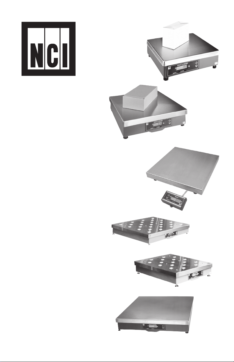
Model
7800
Family
Weight
7820
7880
Classifiers
User’s
Manual
7885
7829
7840
7824
Page 2
CAUTION
Risk of electrical shock. Do not remove cover. No user serviceable
parts inside. Refer servicing to qualified service personnel.
Weigh-Tronix reserves the right to change
specifications at any time.
10/10/05 7800_U.P65 PN 7424-15170i e2 Printed in USA
2
Model 7800 Family Weight Classifiers User’s Manual
Page 3

Table of Contents
Specifications ....................................................................... 4
Initial Setup .......................................................................... 7
Operation ............................................................................. 9
Diagnostics Mode ............................................................... 15
Configuration Mode ............................................................ 20
Calibration Mode ................................................................ 24
Gravity Mode ...................................................................... 27
Re-Calibration Mode .......................................................... 28
Review/Test Scale Settings ................................................ 29
Communication .................................................................. 31
Error Codes ........................................................................ 34
Troubleshooting ................................................................. 35
Spare Parts Listing ............................................................. 37
Model 7800 Family Weight Classifiers User’s Manual
3
Page 4
Specifications
Description
Capacity/Resolution
Agency
Certificates
of Conformance
The NCI 7800 models are digital electronic parcel
bench scales specifically designed for shipping
applications and are Legal-for-Trade. The scales
have built-in intelligence that enables them to be
easily interfaced with a computer or other dataprocessing device.
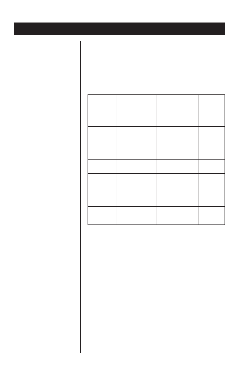
Model Capacity (lb) Capacity (kg) n(max)
7820-50 100 x 0.02 lb 50 x 0.01 kg 5000d
7820-70 150 x 0.05 lb 60 x 0.02 kg 3000d
7820-75 150 x 0.02 lb 75 x 0.01 kg 7500d
7880-50 100 X 0.02 lb 50 x 0.01 kg 5000d
7880-75 150 x 0.05 lb 75 x 0.02 kg 3750d
7880-125 250 x 0.05 lb 100 x 0.02 kg 5000d
7880-150 300 x 0.1 lb 150 x 0.05 kg 3000d
7885-75 150 x 0.05 lb 75 x 0.02 kg 3750d
7829-125 250 x 0.05 lb 100 x 0.02 kg 5000d
7840-125 250 x 0.05 lb 100 x 0.02 kg 5000d
7840-150 300 x 0.1 lb 150 x 0.05 kg 3000d
7824-125 250 x 0.05 lb 100 x 0.02 kg 5000d
7824-150 300 x 0.1 lb 150 x 0.05 kg 3000d
Model 7820
United States: NTEP #95-070
Canada: Ministry of Industry #AM-5076
For use as a Class III device from +5°C through
+40°C
If unit is to be
used as a
commercial
device, all local
reporting and
registration
requirements
must be followed.
4
Model 7800 Family Weight Classifiers User’s Manual
Model 7885
United States: NTEP #02-069
Canada: Ministry of Industry (#AM-5507)
For use as a Class III device from +5°C through
+40°C
Models 7824, 7829, 7840, 7880
United States: NTEP #95-121
Canada: Ministry of Industry #AM-5099
For use as a Class III device from +5°C through
+40°C
Page 5

Dimensions
Model 7820: 14" L x 12.5" W x 4.1" H
Model 7880: 18" L x 18" W x 4.6" H
Model 7885: 18" L x 18" W x 3.0" H
Model 7829: 20" L x 20" W x 5.3" H
Model 7840: 18" L x 24" W x 4.6" H
Model 7824: 24" L x 24" W x 4.6" H
Power Supply
Frequency
Power Requirements
Operating Temperature
Construction
UL/CSA approved in-line power supply with 6’
line cord. (7885 uses wallmount style)
Input: 120 VAC +10%-15%, Standard 3 wire w/
ground
Output: 15 VDC @.3 Amps DC
60 Hz Standard
0.1 amp maximum
42ºF – 104ºF (5ºC – 40ºC)
10% to 95% RH (non-condensing)
Model 7820: Die cast aluminum base with a
stainless steel weigh platter.
Overload protection: Adjustable center stop, fixed
corner stops.
Model 7885: Painted mild steel base with
stainless steel weigh platter.
Overload protection: Fixed center and corner
stops.
Models 7824, 7829, 7840, 7880: Painted mild
steel base with stainless steel weigh platter.
Overload protection: Adjustable center and
corner stops.
Display
½" high, six-digit LCD. Internal display standard
on all models except 7885 (remote only)
Key panel with ZERO and TEST keys.
Optional remote display with 7 ft. cable.
Scale Leveling
Level bubble located under weigh platter. Adjustable feet in each corner to level the scale.
Model 7800 Family Weight Classifiers User’s Manual
5
Page 6

Zero Window
Initial automatic zero setting is ±10% of maximum capacity—active at power up. Manual zero
setting range is ±2% of maximum capacity—
active using the ZERO key.
Under Capacity Limits
Over Capacity Limits
Sealing
Internal Counts
Under capacity indication will be given with
dashes appearing on the bottom line of the
display whenever the display is more than 2
percent below the initial zero value.
Over capacity indication will be given with dashes
appearing in the upper line of the display whenever the weighed item exceeds 9 divisions over
the rated capacity of the unit. The scale will use
the Initial zero value for reference for over
capacity determination.
Access to the calibration switch can be secured
with a lead wire or pressure sensitive security
seal. The remote and primary indicators have no
metrological features that require the use of a
security seal.
The scale has 100,000 internal counts.
Dynamic Response
6
The time from when weight is applied to the scale
until a stable weight display is displayed:
0–1000d 1.5 seconds
1000d+ 2.0 seconds
maximum mean average
Model 7800 Family Weight Classifiers User’s Manual
Page 7

Communications
Initial Setup
Factory default settings: 9600 baud, 7 data bits,
even parity, 1 stop bit.
Standard 9-pin pass through RS-232 interface
cable included. Not a null modem.
RS-232 bidirectional, configurable 1200 to 19.2K
baud. Transmits weight and scale status whenever ASCII “W” <CR> is sent by a remote device.
Unpacking the Scale
Installing the Scale
1. Remove contents of the shipping container.
2. Inspect the scale for evidence of shipping
damage. Immediately report any damage to
the shipper.
1. Mount the scale on a stable, level surface
that is free from air currents and vibration. Be
sure the scale platter does not touch any
adjacent surfaces.
2. To install the scale surface flush with a
countertop, use the dimensions on the
following page to guide construction.
Model 7800 Family Weight Classifiers User’s Manual
7
Page 8

Model 7820
Scale Dimensions Min. Cut-Out Dimensions
D 12.5 in. (31.7 cm) 13.25 in. (33.7 cm)
W 14 in. (35.6 cm) 14.75 in. (37.5 cm)
H 4.1 in. (10.4 cm)*
*Adjustable to 4.6 in. (11.7 cm)
Model 7880
Model 7885
Model 7829
Model 7840
Model 7824
Scale Dimensions Min. Cut-Out Dimensions
D 18 in. (45.7 cm) 18.75 in. (47.6 cm)
W 18 in. (45.7 cm) 18.75 in. (47.6 cm)
H 4.6 in. (11.6 cm)*
*Adjustable to 5.1 in. (12.9 cm)
Scale Dimensions Min. Cut-Out Dimensions
D 18 in. (45.7 cm) 18.75 in. (47.6 cm)
W 18 in. (45.7 cm) 18.75 in. (47.6 cm)
H 3.0 in. (7.6 cm)*
*Adjustable to 3.5 in. (8.9 cm)
Scale Dimensions Min. Cut-Out Dimensions
D 20 in. (50.8 cm) 20.75 in. (52.7 cm)
W 20 in. (20.8 cm) 20.75 in. (52.7 cm)
H 5.3 in. (13.5 cm)*
*Adjustable to 5.8 in. (14.7 cm)
Scale Dimensions Min. Cut-Out Dimensions
D 24 in. (61.0 cm) 24.75 in. (62.9 cm)
W 18 in. (45.7 cm) 18.75 in. (47.6 cm)
H 4.6 in. (11.7 cm)*
*Adjustable to 5.1 in. (12.9 cm)
Scale Dimensions Min. Cut-Out Dimensions
D 24 in. (61.0 cm) 24.75 in. (62.9 cm)
W 24 in. (61.0 cm) 24.75 in. (62.9 cm)
H 4.6 in. (11.7 cm)*
*Adjustable to 5.1 in. (12.9 cm)
3. Loosen the collars or jam nuts on the leveling
feet. Level the scale by using the level bubble
under the scale platter as a guide. Be sure all
four feet are in firm contact with the counter,
then tighten all collars and jam nuts.
4. Make sure all power cords, remote display
cables, etc., are not touching the live weighing surface.
5. Plug the unit into an appropriate voltage
outlet that is properly grounded.
8
Model 7800 Family Weight Classifiers User’s Manual
Page 9

Operation
Power Up Test Sequence
If RAM or ROM error
is reported, you must
press the TEST key to
acknowledge the
condition. See Error
Codes section.
Performing a Normal
Weighment
When first powered
on, if the scale is
outside the ± 10% zero
window, center dashes
are displayed. “- - - -”
If necessary, reapply
power to reset the
initial zero setting.
Refer to the Trouble-
shooting section if the
problem persists.
When the scale is first powered on, it will perform
a test sequence. During this sequence, the
display will show the following:
• The model number and the software
revision level.
• A numeric counting test for all segments of
the display. During this test, a test of
Random Access Memory (RAM) and a test
of Read Only Memory (ROM) is performed.
If everything is OK, the display will show zero
weight and the scale is ready for use.
1. With the scale powered on, make sure the
scale platter is empty and the display is at
zero. If it is not, press the ZERO key...
0.00 is displayed.
2. Place an item to be weighed on the scale
platter...
The scale will display the gross weight.
3. Remove the item from the scale platter.
Model 7800 Family Weight Classifiers User’s Manual
9
Page 10
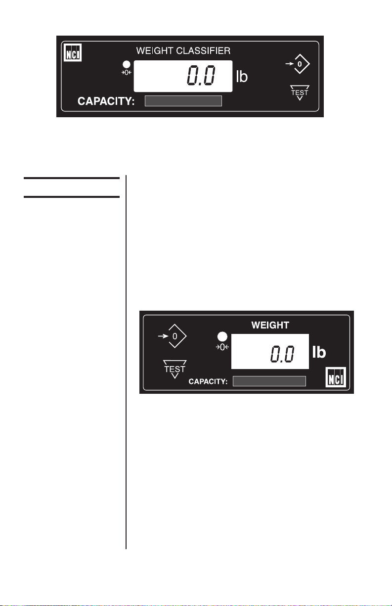
7820, 7880, 7829, 7840 and 7824 resident display
Operation Controls
7885 or Optional
Remote Display
ZERO Key – The ZERO key will zero the scale if
weight is stable, and acts as the NO or SCROLL
key in the Menu Mode and as the INCREASE
key in the Gravity Mode.
TEST Key – The TEST key can be used to
perform the initial power-up test sequence, recall
diagnostic routines, or view the configuration
information. This key also functions as YES or
ACCEPT in the Menu Mode and as the DECREASE key in the Gravity Mode.
All NCI 7800 bench scales, except the 7885, can
have an optional remote display. If a remote
display with keyboard is used, then Switch 3
(shown in Figure 1) determines which display
keyboard is funcitional.
10
Switch 3 Settings:
Closed= internal display keys operational
Open= external display keys operational
The remote display must be connected to the
RJ45 port (DISPLAY) prior to power up to
operate properly.
Model 7800 Family Weight Classifiers User’s Manual
Page 11
Accessing the
Menu Mode
The 7800 models power up ready for weighing
operations. Access the Menu mode by setting
Switch 1 shown in Figure 1 or 2 to the OPEN or
Menu mode position.
Accessing the
Gravity Mode
Figure 1
7820 Switch
Location
Access the Gravity setting mode by setting
Switch 2, shown in Figure 1 or 2, to the OPEN or
Gravity mode position.
Top View of 7820 Scale with Platter Removed
Model 7800 Family Weight Classifiers User’s Manual
11
Page 12

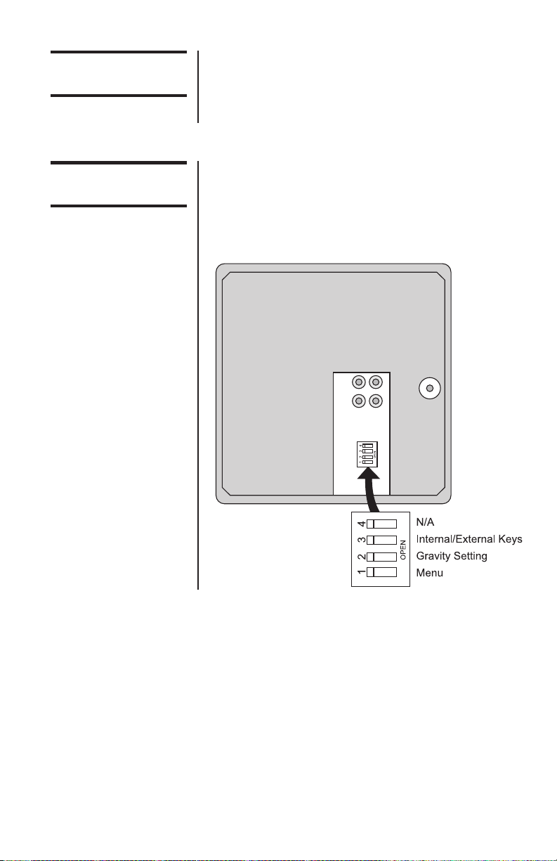
Figure 2
7824, 7829, 7840,
7880, 7885 Switch
Location
Bottom View of Models 7824, 7829, 7840,
7880 and 7885
Menu Mode
Gravity Mode
With Switch 1 in the Menu mode or OPEN
position, there are four modes available to you.
They are as follows:
DIAG (Diagnostic Mode) – To test areas of
the scale’s function
CONF (Configuration Mode) – To configure
the scale for your application
CAL (Calibration Mode) – To calibrate the
scale
RE-CAL (Recalibration Mode) – To change
resolution and rounding type
The structure for these menus is shown in Figure
3. Specific information about each mode followed
by step-by-step instructions for accessing them
are described in the following pages.
With Switch 2 in the Gravity Mode or OPEN
position, you may increase the local gravity value
by pressing the ZERO key, or decrease the value
by pressing the TEST key.
12
Model 7800 Family Weight Classifiers User’s Manual
Page 13

Figure 3
Menu Structure
Model 7800 Family Weight Classifiers User’s Manual
13
Page 14

Alternative Calibration
Points
The NCI 7800 bench scales allow calibration
using less than full capacity weights. See Table 1
for alternative weights that can be used to
calibrate your scale for its designated capacity.
Table 1
Alternative
Calibration Points
Baud Rate and Parity
Options
Table 2
Baud Rate and
Parity Options
The databits and stop
bits default values are
7 data bits and 1 stop
bit. These are not
configurable.
Alternative
Capacity Calibration Weights
100 x .02 lb 10, 50, 100 lb
50 x .01 kg 10, 25, 50 kg
150 x .05 lb 10, 50, 150 lb
60 x .02 kg 10, 30, 60 kg
150 x .02 lb 10, 50, 150 lb
75 x .01 kg 10, 50, 75 kg
75 x .02 kg 10, 50, 75 kg
250 x .05 lb 50, 100, 250 lb
100 x .02 kg 10, 50, 100 kg
300 x .1 lb 50, 100, 300 lb
150 x .05 kg 10, 50, 150 kg
Display Baud Parity
12 E 1200 Even
24 E 2400 Even
48 E 4800 Even
96 E 9600 Even
*
19.2 E 19.2K Even
12 o 1200 Odd
24 o 2400 Odd
48 o 4800 Odd
96 o 9600 Odd
19.2 o 19.2K Odd
12 n 1200 None
48 n 4800 None
96 n 9600 None
19.2 n 19.2K None
14
*Default Factory Settings
Model 7800 Family Weight Classifiers User’s Manual
Page 15

Diagnostics Mode
Diagnotic (DIAG) Mode
Tip: Quickly and easily
gain access to the
Diagnostic mode
directly from the front
panel without opening
the scale or setting
switches as follows:
Press and hold the
TEST key. The display
will flash 78--, the
program version, and
then “_ _ _ _.” Now
release the TEST key.
To exit the Diagnostic
mode press the ZERO
key until DONE is
displayed, then press
the TEST key to return
to normal weighing
mode.
IMPORTANT: Internal
rocker switches will be
ignored until you exit
this special mode or
power reset the scale.
The Diagnostic (DIAG) Mode menu allows
testing of specific areas of the scale’s function
and viewing of current configuration settings.
Areas to test the scale’s function are:
DISPLAY (DISP) – Shows the version and
revision of the software, followed by a display
segment test.
RAM (RA) – Performs a non-destructive test of
RAM in the processor. Displays PASS or FAIL.
ROM (RO) – Performs a checksum of all locations of ROM in the processor. Displays PASS or
FAIL.
INPUT/OUTPUT (I/O) – Data is output by the
scale and through the use of a loopback connector. The data is immediately read back into the
receive channel and verified against what was
sent. PASS or FAIL is displayed. Requires a
jumper (short) between transmit and receive data
lines.
DIVISION TEST, w/AZT (DIV-A) – Weight data
is normalized to 100,000 counts of displayed
resolution. AZT is enabled.
DIVISION TEST, w/o AZT (DIV-N) – Weight data
is normalized to 100,000 counts of displayed
resolution. AZT is disabled.
Areas to view current configuration settings are:
Filter, Protocol, Baud, Capacity, Type, Units,
Prtout and Gravity Setting.
Model 7800 Family Weight Classifiers User’s Manual
15
Page 16

If you encounter any
failure in these tests,
contact your local
Weigh-Tronix dealer.
Follow these steps to access the tests in the
DIAG menu.
1. From normal weighing mode, move Switch 1
to the MENU Mode or OPEN position. (See
Figure 1 or 2).
DIAG is displayed.
2. Press the TEST key...
DISP is displayed. This stands for
display.
3. Press the TEST key to perform the display
test described earlier...
Display test is performed and the display
shows DISP after the test is completed.
4. Press the ZERO key...
RA is displayed. This stands for the RAM
test.
Press the ZERO key to
scroll through lists of
selections.
Press the TEST key to
make a selection.
To skip a test, press
the ZERO key to scroll
to the next test.
16
Model 7800 Family Weight Classifiers User’s Manual
5. Press the TEST key to perform the RAM
test...
PASS or FAIL is displayed briefly; then
RA.
6. Press the ZERO key...
RO is displayed. This stands for the
ROM test.
7. Press the TEST key to perform the ROM
test...
PASS or FAIL is displayed briefly; then
RO.
8. Press the ZERO key...
I/O is displayed. This stands for the
INPUT/OUTPUT test. .
Page 17

DIAG will flash every
15 seconds during the
high resolution test as
a reminder that you
are doing a test and
not seeing normal
weight readings.
9. With a loopback connector in place, press
the TEST key to perform the I/O test...
PASS or FAIL is displayed briefly, then
I/O.
10. Press the ZERO key . . .
DIV-A is displayed. This stands for the
high resolution DIVISION TEST W/ AZT
enabled.
11. Press the TEST key to perform this test...
The display shows the weight on the
scale at a resolution of 100,000 counts.
12. Press the TEST key to stop the test...
DIV-A is displayed.
13. Press the ZERO key...
DIV-N is displayed. This stands for the
high resolution DIVISION TEST w/o AZT
enabled.
The remaining
selections are for
viewing current
settings only. You can
scroll through the
menu to verify the
settings, but to make
changes, you must
enter configuration or
calibration.
Model 7800 Family Weight Classifiers User’s Manual
14. Press the TEST key to perform this test...
The display shows the weight on the
scale at a resolution of 100,000 counts.
15. Press the TEST key to stop the test...
DIV-N is displayed.
16. Press the ZERO key...
FILT is displayed. This stands for filter-
ing.
17. Press the TEST key...
The current filter setting, FAST or SLO,
is displayed.
17
Page 18

18. Press the ZERO key...
PROT is displayed. This stands for
protocol.
19. Press the TEST key...
The current serial protocol selection is
displayed.
20. Press the ZERO key...
BAUD is displayed. This stands for baud
rate.
21. Press the TEST key...
The current baud rate and parity selection is displayed.
22. Press the ZERO key...
CAP is displayed. This stands for capac-
ity.
23. Press the TEST key...
18
The current capacity/resolution selection
is displayed.
24. Press the ZERO key...
TYPE is displayed. This stands for
rounding type (classifier or scale).
25. Press the TEST key...
The current rounding type, SCALE for
standard rounding or CLASS for classifier rounding, is displayed.
26. Press the ZERO key...
UNITS is displayed. This stands for unit-
of-measure.
Model 7800 Family Weight Classifiers User’s Manual
Page 19

27. Press the TEST key...
The current unit-of-measure LBS (for
pounds) or 1000G (for kilograms), is
displayed.
28. Press the ZERO key...
PRTOUT is displayed. This stands for
output print format.
29. Press the TEST key...
The current output print format is displayed. See Table 3 for details.
30. Pres the ZERO key. . .
LOC-GR is displayed. This stands for
local gravity.
31. Press the TEST key. . .
The current local gravity setting is
displayed.
32. Press the ZERO key . . .
CAL-GR is displayed. This stands for
calibration gravity.
33. Press the TEST key. . .
The current calibration gravity settings is
displayed.
34. When you are finished, press the ZERO key,
until DONE is displayed, then press the
TEST key to return to the top menu level...
DIAG is displayed.
Or close Switch 1 to return to normal weighing mode.
Model 7800 Family Weight Classifiers User’s Manual
19
Page 20

Configuration Mode
The Configuration (CONF) mode menu allows
scale configuration for your specific application
needs. The items you can configure are as
follows:
FILTERING (FILT) – Choose between FAST and
SLO filtering. SLO should be chosen in areas
susceptible to vibration. Choose FAST filtering
for more stable conditions.
Baud (BAUD) – Choose a baud and parity from
Table 2.
Protocol (PROT) – Select the RS-232 communication protocol.
NCI – NCI standard
8213 – 8213 compatible (Mettler-Toledo)
3835 – NCI 3835
SMA – Scale Manufacturing Association
AUTO-1 – Auto print operation (Type-1)
20
AUTO-2 – Auto print operation (Type -2)
PRINT – Manual print operation
PRTOUT – Choose an output data format from
Table 3 for use with AUTO-1, AUTO-2 or PRINT
protocol selection.
Access the menu mode as described in Access-
ing the Menu Mode.
1. From the DIAG display, press the ZERO key
until CONF is displayed, or from the normal
weighing mode, move Switch 1 to the Menu
ode or the OPEN position; then press the
ZERO key until CONF is displayed.
Model 7800 Family Weight Classifiers User’s Manual
Page 21

2. Press the TEST key...
FILT is displayed.
3. Press the TEST key...
The current setting, FAST or SLO, is
displayed.
4. Use the ZERO key to toggle between the
two choices. Press the TEST key when
the choice you want is displayed. The
choice is accepted and the display shows
FILT.
5. Press the ZERO key...
BAUD is displayed.
6. Press the TEST key...
The current baud and parity choice is
displayed.
7. Use the ZERO key to scroll the choices
found in Table 2. When the choice you
want is displayed, press the TEST key...
See “Print Modes” for
a description of the
available autoprint and
manual print modes of
operation.
Model 7800 Family Weight Classifiers User’s Manual
The choice is accepted, and the
display shows BAUD.
8. Press the ZERO key until...
PROT is displayed.
9. Press the TEST key...
The current RS-232 communication
protocol is displayed.
10. Press the ZERO key to scroll through the
choices. When the choice you want is
displayed, press the TEST key...
The choice is accepted and the
display shows PROT.
21
Page 22

The PRTOUT configuration selection (in the
CONF menu) allows
you to select the
format of the data
string that is transmitted during autoprint
(AUTO-1 or AUTO-2)
or the manual print
(PRINT) modes. This
does not apply to the
other protocol modes.
11. Press the ZERO key...
PRTOUT is displayed. This stands for
printout.
12. Press the TEST key...
The current printout format is displayed.
13. Press the ZERO key to scroll through the
choices. When the choice you want is
displayed, press the TEST key...
Your choice is accepted and the display
shows PRTOUT.
Table 3
OUTPUT PRINT FORMATS
Formatted Output Data String Selection Display
<LF> WWW.WW uu <CR> <LF> LFuuLF*
<LF> WWW.WW uu <CR> LFuu—
<LF> WWW.WW <CR> <LF> LF—LF
<LF> WWW.WW <CR> LF——
WWW.WW uu <CR> <LF> —uuLF
WWW.WW uu <CR> —uu—
WWW.WW <CR> <LF> ——LF
WWW.WW <CR> ———
*Default factory setting
Where: <LF> ...... Represents the line feed character (ØA hex)
W ........... Represents a weight digit character
uu .......... Represents the unit-of-measure characters (lb or kg)
<CR> ..... Represents the carriage return character (ØD hex)
14. When finished configuring your scale, press
the ZERO key until DONE is displayed; then
press the TEST keys, or close Switch 1 to
return to the normal weighing mode.
22
Model 7800 Family Weight Classifiers User’s Manual
Page 23

Print Modes
The 78XX provides three options for transmitting
displayed weight without requiring a remote
device to initiate the request for weight to the
scale. These options are selectable in the CONF
setup menu PROT and are as follows:
AUTO-1:
To avoid potential
erroneous weight
values from being
transmitted, create
enough instantaneous
motion on the platform
to avoid a recapture of
a stable weight that
might occur if the item
were removed slowly.
AUTO-2:
PRINT:
Weight is automatically transmitted after weight
is removed from the scale platform. The last
“stable” weight prior to removing the item will be
“sent,” as soon as the displayed weight returns to
within five display divisions (i.e. 5d). This option
is normally used in applications where items are
added to a box already placed on the scale, but
where only one weight data transaction is to
occur. See note at left.
Weight is automatically transmitted when the
item is placed on the scale and the weight
stabilizes. This option is normally used in an
application where the item placed on the scale is
sealed and ready for the shipment weight to be
registered. The minimum stable weight required
to trigger an auto SEND is set at five display
divisions (i.e. 5d).
Weight is transmitted only when the TEST button
on the display panel is pressed. The TEST button
is redefined as a SEND key when in the normal
weight mode only. See Note 2 below. On some
specially modified units, the serial port connector
or an additional internal connection to the display
TEST button can also be utilized for a remote
push button to initiate the manual send sequence.
Model 7800 Family Weight Classifiers User’s Manual
23
Page 24

NOTES:
(1) The output print formats for AUTO-1, AUTO-
(2) The TEST button will retain its test function
3) While in AUTO-1, AUTO-2, or manual print
Calibration Mode
The Calibration (CAL) Mode menu lets you
calibrate your scale. The items in the calibration
menu are as follows:
2 and manual print operation are defined in
Table 3 and set in the PRTOUT setting of the
CONF menu.
(i.e. will not be redefined as a SEND key)
when displayed weight is at zero as indicated
when the Center-Zero indicator is on.
modes, scale will not respond to external
serial commands.
24
POUNDS/KILOGRAMS (LBS or 1000 Gr) –
Selects the unit of measure of your calibration
test weights (lb or kg).
SCALE or CLASS – Selectable only when
calibrated in LBS (lb) mode. Selection of SCALE
rounds weight at 0.5 divisions. Selection of
CLASS sets device up as a weight classifier
rounding at 0.9 divisions.
Model 7800 Family Weight Classifiers User’s Manual
Page 25

Step-by-Step
Insutructions for CAL
Mode
CAPACITY (100.02, 150.05, 250.05, 300.1, etc.)
– Select the capacity of the scale.
Follow these steps to calibrate the scale. Refer to
Figure 3 on Page 18.
1. From the DIAG display, press the ZERO key
until CAL is displayed, or from the normal
weighing mode, move Switch 1 to the Menu
mode or OPEN position. Press the ZERO
key until CAL is displayed.
2. Press the TEST key...
LBS (lb) or 1000G (kg) is displayed.
3. Press the ZERO key to toggle between the
choices. When the choice you want is
displayed, press the TEST key to accept...
The choice is accepted.
If LBS (lb) was selected, the scale will
display CLASS.
If 1000G (kg) was selected, scale
displays the present capacity setting.
Proceed to Step 5.
4. Press the ZERO key to toggle between
SCALE and CLASS. When the choice you
want is displayed, press the TEST key...
That choice is accepted and a scale
capacity is displayed.
Example: 100.02
If a different capacity selection is desired,
press the ZERO key to scroll through the
choices.
Model 7800 Family Weight Classifiers User’s Manual
25
Page 26

The capacity selected
must correlate with the
rated capacity of the
scale noted on the
serial tag.
5. When the desired capacity is displayed,
press the TEST key...
That choice is accepted and LOAD 0 is
displayed.
6. Clear all weight from the scale platter and
press the TEST key...
After a brief wait LOAD xx is displayed.
Alternate calibration points can be
chosen using the ZERO key to scroll
between choices (see Table 1).
If this procedure is
attempted without any
calibration weights
applied, the scale will
abort the process and
retain the original
calibration data.
7. Place the appropriate calibration weights on
the scale and press the TEST key. After a
brief wait...
DONE is displayed.
8. Remove all calibration weights from scale.
9. Press the TEST key...
DIAG is displayed, or return Switch 1 to
the closed position. The scale returns to
normal weighing mode.
The scale is now tested, configured, and calibrated. It is ready for use in your application.
26
Model 7800 Family Weight Classifiers User’s Manual
Page 27

Gravity Mode
The CAL-GR and
LOC-GR values may
be viewed anytime.
See Review/Test
Scale Setting section.
Warning: Using this
feature in “sealed”
applications may be
subject to approval by
the appropriate
governing agency
at the end-users site.
Gravity value roles
‘over’ at 9.8400 and
rolls ‘under’ at 9.7700.
The Gravity Mode feature provides a means of
adjusting the scale’s internal calibration factors to
compensate for variations in acceleration due to
gravity at different geographic locations. These
differences can cause a given mass to indicate a
slightly different weight at an end-user’s (local)
site than it did at the Calibration (CAL) site.
To make the adjustment, you must know the
value of the gravity constant for the local site.
This value is expressed in meters per second,
per second (i.e., m/s2). It is not necessary to
calibrate the scale, therefore, no calibration
weights are needed to make this adjustment.
The scale maintains two gravity setting values.
The first is the “calibration-site” value known as
CAL-GR. The second is the end-user or “localsite” value and is known as LOC-Gr. When the
scale was originally calibrated at the factory, the
CAL-GR and LOC-GR values were both set to
9.8040 which is the gravity constant for the
manufacturing site.
To adjust the displayed weight value, you must
enter the local gravity value.
To enter the Gravity Mode, set Switch 2 to the
OPEN position. The display will indicate the
current “local” gravity value. Press the ZERO key
to increment the value or the TEST key to
decrement the value. The gravity value will
change in steps of .0002. When the correct value
is displayed, simply return Switch 2 to the
CLOSED position. The scale will now use this
new relationship between calibration and local
gravity for its weight calculations.
Model 7800 Family Weight Classifiers User’s Manual
27
Page 28

Re-Calibration Mode
The re-calibration RE-CAL mode menu lets you
change the scale resolution (150lb / 75kg capacities only) or rounding method without using any
calibration weights. If you want to change the unit
of measure operation, you must perform a full
calibration using test weights.
For a scale originally calibrated in the lb. mode,
you may also change rounding methods (i.e.,
Step-by-Step Instructions
for RE-CAL mode
Return to normal
operating mode
by pressing the
SW-1 switch
scale or classifier).
Follow these steps to re-configure your scale
(without weights). Refer to Figure 3.
1. From the normal weighing mode, move
Switch 1 to the Menu mode or OPEN position...
2. Press the ZERO key until...
3. Press the TEST key...
DIAG is displayed.
RE-CAL is displayed.
28
ROUND is displayed.
To change the weight rounding method,
press the TEST key. The current rounding method is displayed.
4. Press the ZERO key to toggle between
SCALE and CLASS.
5. When the choice you want is displayed,
press the TEST key.
6. To change the capacity/resolution, press the
ZERO key until RESO is displayed.
7. Press the TEST key. The current capacity/
resolution setting is displayed.
Model 7800 Family Weight Classifiers User’s Manual
Page 29

8. Press the ZERO key until desired capacity/
resolution is displayed.
9. Press the TEST key to select a new capacity/
resolution.
10. Close Swtich 1 to return to normal weighing
mode.
Review/Test Scale Settings
The TEST key located on the front panel lets you
perform some basic system diagnostics, as well
as review the current system settings without
having to access switches inside the scale.
If you press and release the TEST key, the
display will show the scales model number,
version-revision, and performs a display
test. To review the current system settings,
press and hold the TEST key until the
display shows, “
Model 7800 Family Weight Classifiers User’s Manual
- - - - - - - -
“.
29
Page 30

Press the ZERO key
to move to the next
item in the menu
Press the TEST key
to select the displayed item to run or
view.
IMPORTANT:
Internal rocker
switches will be
ignored until you exit
this special mode or
power reset the
scale.
30
When finished running tests or viewing the
settings, press the ZERO key until DONE is
displayed. Then press the TEST key to return to
normal (i.e., weighing) mode of operation.
Model 7800 Family Weight Classifiers User’s Manual
Page 31

Communication
The NCI 7800 family scales come factory configured as a serial RS-232 interface device.
There is one 9-pin DE type female connector
accessible at the rear of the unit. The functional
pinout of this connector is compatible with a
standard PC with a pass through cable.
Communications Enabled
Interface Cable
Specifications
JMP 1 Pins 1, 4 and 6,
and JMP 2 Pins 7 and
8 are internally
jumpered inside the
scale.
Serial commands will be responded to only when
the scale is in the normal operating mode and
Switch 1 on the main board is in the CLOSED
position.
DE-9 Female Scale DE-9 Male Host
Pin Name Direction Pin Name Direction
1. JMP 1 - 1. DCD IN
2. TXD OUT 2. RXD IN
3. RXD IN 3. TXD OUT
4. JMP 1 - 4. DTR OUT
5. SG - 5. GRD -
6. JMP 1 - 6. DSR IN
7. JMP 2 - 7. RTS OUT
8. JMP 2 - 8. CTS IN
9. NC - 9. RI IN
Model 7800 Family Weight Classifiers User’s Manual
31
Page 32

NCI Serial
Communications
Protocol
SYMBOL KEY:
<ETX> End of text character (Ø3 hex)
<LF> Line feed character (ØA hex)
<CR> Carriage return character (ØD hex)
<SP> Space (2Ø hex)
x Character from display including
minus sign.
hh Two status bytes
uu Unit of measure (lb, kg, oz, g, etc.
using ANSI standard abbreviations)
Standard Commands
W<CR>
Scale Response
<LF>xxxx.xxuu<CR>
<LF>hh<CR><ETX>
Results
Returns decimal weight with units plus scale
status.
S<CR>
Scale Response
<LF>hh<CR><ETX>
Results
Returns to scale status.
Z<CR>
Scale Response
<LF>hh<CR><ETX>
Results
Scale is zeroed, returns status.
32
Model 7800 Family Weight Classifiers User’s Manual
Page 33

Optional Commands
H<CR>
Scale Response
<LF>xxxx.xxxuu<CR>
<LF>hh<CR><ETX>
Results
Returns decimal wt in 10x with units plus scale
status.
d<CR> (for factory diagnostics only)
Scale Response
xxxxxx (div-A) <CR>
or
xxxxxx (div-n) <CR>
Results
Returns weight normalized to 100,000 division
with AZT on/off. Protocol must be set for NCI and
the scale must be in the “DIAG” (diagnostics)
sub-menu. Otherwise, the scale will respond with
the unrecognized command response.
All other commands
Scale Reponse
<LF>?<CR><ETX>
Results
Unrecognized command
Contact Customer Service for protocol details or
visit our website at www.wt-nci.com
Model 7800 Family Weight Classifiers User’s Manual
33
Page 34

Error Codes
Any system errors detected by the scale will be
displayed as the letter E followed by a two-digit
error code. Press the TEST key to continue
operation. If a calibration error occurs, the only
way to clear it is by recalibrating the scale.
The error codes are broken down into two
hexadecimal numbers, with each bit defining a
single error condition. The error codes are
defined as follows:
34
Model 7800 Family Weight Classifiers User’s Manual
Page 35

Troubleshooting
Perform the following steps in the order presented until the described problem is corrected. If
the problem cannot be corrected, contact your
Weigh-Tronix service provider.
No Power (Display is Blank)
1. Check that the primary side of the cord is
plugged into the AC outlet, and the secondary side is properly connected to the power
jack on the back of the scale.
2. Replace the power supply.
3. Replace the display board.
4. Replace the main board.
Missing or extra segments on display
1. Replace the display board.
2. Replace the main board.
Scale will not return to zero, or incorrect
weight is displayed
1. Press the ZERO key.
2. Check for interference of weighing platform.
3. Power off, remove all items from the platter,
and then power on the scale.
4. Recalibrate the scale.
5. Replace the load cell.
6. Replace the main board.
Display shows unrecognized characters
1. Check software PROM for proper insertion.
2. Check display cables for the proper connection.
3. Replace PROM.
4. Replace the display board.
5. Replace the main board.
Model 7800 Family Weight Classifiers User’s Manual
35
Page 36

Display shows under “_ _ _ _” dashes
(Indicates that the scale is below zero or under
capacity.)
1. Verify that weigh platter is on the scale.
2. Press the ZERO key.
3. Power off, remove any items from the platter,
and then power on the scale.
4. Recalibrate the scale.
5. Replace the load cell.
6. Replace the main board.
Display shows center“
_ _ _ _
” dashes
(Indicates that the scale is outside zero capacity
of ±2%.)
1. Verify that weigh platter is on the scale.
2. Press the ZERO key.
3. Power off, remove any items from the platter,
and then power on the scale.
4. Recalibrate the scale.
5. Replace the load cell.
6. Replace the main board.
Display shows upper “
_ _ _ _
“ dashes
(Indicates the scale is over capacity.)
1. Remove all items from the scale.
2. Press the ZERO key.
3. Power off, and then power on the scale.
4. Recalibrate the scale.
5. Replace the load cell.
6. Replace the main board.
Scale is not transmitting data to the host
device
1. Check cable connection at both the rear
of the scale and the host device.
2. Check communication setting and baud rate
on both scale and software.
3. Perform I/O loopback test.
36
Model 7800 Family Weight Classifiers User’s Manual
Page 37

4. Replace the cable.
5. Replace the main board.
The ZERO key and the TEST key do not
function
1. Open display enclosure and verify that the
2. Verify internal/external switch setting. See
2. Replace the display panel.
3. Replace the display PCB.
4. Replace the display cable.
5. Replace the main PCB.
Spare Parts Listing
DESCRIPTION PART NUMBER
Keyboard Panel 1163-13204
Display PCB 7405-15465
Main PCB 7405-14704-2
Power Supply - in-line 1148-15536
Power Supply - wallmount 1148-15535
(7885)
RS-232 Cable 1140-13842
7820-50 Loadcell 7154-16335-50
7820-70 Loadcell 7154-16333-100
7820-75 Loadcell 7154-16335-100
7880-50 Loadcell 7154-16365-75
7880-75 Loadcell 7154-16365-100
7885-75 Loadcell 7154-16335-100
7880-125, 150 Loadcell 7154-16365-150
7829-125 Loadcell 7154-16365-150
7840-125, 150 Loadcell 7154-16365-150
7824-125, 150 Loadcell 7154-16365-150
Remote Display Kit 7300-16577-01
7820 Feet 7075-15475-02
7880, 29, 40, 24, 85 Feet 7075-13082
keypad cable is still installed correctly.
Operation Controls section.
Model 7800 Family Weight Classifiers User’s Manual
37
Page 38

Notes
38
Model 7800 Family Weight Classifiers User’s Manual
Page 39

Model 7800 Family Weight Classifiers User’s Manual
39
Page 40

1000 Armstrong Drive
Fairmont, MN 56031
Telephone: 507-238-4461
Facsimile: 507-238-4195
E-Mail: service@wt-nci.com
www.wt-nci.com
 Loading...