

Page 1
Model 7600
Family
Postal Weight Classifiers
Model 7620
Model 7680
User’s Manual
Page 2
CAUTION
Risk of electrical shock. Do not remove cover. No user serviceable
parts inside. Refer servicing to qualified service personnel.
Weigh-Tronix reserves the right to change
specifications at any time.
November 29, 2006 7600_U.P65 PN 7424-15384H e2 Printed in USA
2
Model 7600 Family PWC User’s Manual
Page 3

Table of Contents
Description .......................................................... 4
Specifications...................................................... 4
Initial Setup ......................................................... 9
Operation .......................................................... 10
7600 Menu Structure......................................... 14
7600 Menu Structure - Glossary ....................... 15
Diagnostics Mode.............................................. 18
Configuration Mode........................................... 21
Calibration Mode ............................................... 23
Re-Calibration Mode ......................................... 26
Gravity Mode..................................................... 28
Review Scale Settings....................................... 30
Communications ............................................... 31
Error Codes....................................................... 33
Troubleshooting ................................................ 34
Spare Parts Listing............................................ 37
Model 7600 Family PWC User’s Manual
3
Page 4

Description
Specifications
The NCI 7600 models are digital electronic letter
and parcel bench scales specifically designed for
mail manifest and shipping applications. They are
fast, accurate and reliable. All models use the
Quartzell® transducers for true digital signal
response for increased throughput capabilities
for weighing letters, flats and parcels using one
scale.
Capacity/
Resolution
Default for 100 lb
scale
Now an approved
Weights & Measures
resolution
7620-32 70 lb/30 kg
0-10 lb x 0.05 oz 10-70 lb x 0.2 oz
0-10 lb x 0.002 lb 10-70 lb x 0.02 lb
0-5 kg x 0.001 kg 5-30 kg x 0.005 kg
n1-5000 n2-6000
7620-50 100 lb/50 kg (100L Mode low res)
0-10 lb x 0.1 oz 10-100 lb x 0.5 oz
0-10 lb x 0.01 lb 10-100 lb x 0.05 lb
0-5 kg x .005 kg 5-50 kg x 0.02 kg
n1-1600 n2-5000
7620-50 100 lb/50 kg (100H Mode high res)
0-10 lb x 0.05 oz 10-100 lb x 0.5 oz
0-10 lb x 0.005 lb 10-100 lb x 0.02 lb
0-5 kg x .002 kg 5-50 kg x 0.01 kg
n1-3200 n2-5000
7620-75 150 lb/75 kg
0-10 lb x 0.1 oz 10-150 lb x 0.5 oz
0-10 lb x 0.005 lb 10-150 lb x 0.02 lb
0-5 kg x 0.005 kg 5-75 kg x 0.01 kg
n1-2000 n2-7500
4
Model 7600 Family PWC User’s Manual
Page 5

7680-75 150 lb/75 kg
0-10 lb x 0.1 oz 10-150 lb x 0.5 oz
0-10 lb x 0.005 lb 10-150 lb x 0.02 lb
0-5 kg x 0.005 kg 5-75 kg x 0.01 kg
n1-2000 n2-7500
The 7600 family of bench scales can be used for
general weighing applications when configured
as a scale, or for postal and shipping applications when configured as a weight classifier.
Agency
Certificates of
Conformance
Dimensions
Power Supply
Frequency
Model 7620 is approved as legal for trade:
United States - NTEP COC #95-071
Canada - Ministry of Industry #AM 5074
Europe - EEC (OIML) #UK 2476
For use as a Class III device from +5º to 40ºC
Model 7620:
14" L x 12.5" W x 4.2" H
356 mm L x 318 mm W x 107 mm H
Model 7680:
18" L x 18" W x 4.6" H
457 mm L x 457 mm W x 117 mm H
UL/CSA approved inline power supply with 6'
long standard wire line cord with ground
Input: 120 VAC + 10% - 15%
Output: 15 VDC @ .3 Amps
60 (±3) Hz Standard
Model 7600 Family PWC User’s Manual
5
Page 6

Power Requirements
0.1 amp maximum
Operating Temperature
Construction
Overload Protection
Display
42º F - 104º F
+5º C to + 40º C
10% to 95% RH (non-condensing)
Model 7620:
Die cast aluminum base and load bridge.
Plastic ABS or stainless steel weigh platter.
Aluminum quartz digital load cell
Model 7680:
Painted mild steel base with stainless steel
weigh platter. Aluminum quartz digital load cell
Model 7620:
Adjustable center stop
Fixed corner stops
Model 7680:
Adjustable center stop
Adjustable corner stops
400% static loading
200% dynamic loading
Internally mounted 1/2" high seven-digit LCD
Key panel with ZERO and UNITS function keys
Optional remote display with 7ft cable
Scale Leveling
Zero Window
6
Level bubble under weigh platter
Adjustable feet in each corner
Automatic zero setting is ±10% of maximum
capacity—active at power up. Manual zero
setting range is ± 2% of maximum capacity—
active using the ZERO key.
Model 7600 Family PWC User’s Manual
Page 7

Under Capacity Limits
Under capacity indication will be given with
dashes appearing on the bottom line of the
display whenever the display is more than 10
division below the initial zero value.
Over Capacity Limits
Sealing
Internal Resolution
Dynamic Response
Communications
Over capacity indication will be given with dashes
appearing in the upper line of the display whenever the weighed item exceeds 9 divisions over
the rated capacity of the unit. The scale will use
the initial zero value for reference for over
capacity determination.
Access to the calibration switch can be secured
with a lead wire or pressure sensitive security
seal. The remote and primary indicators have no
metrological features that require the use of a
security seal.
1 part in 2,000,000
The time interval of weight applied to scale until a
stable weight:
Transmitted Displayed
0 - 1000d 500 msec 1200 msec
1000d+ 750 msec 1400 msec
Maximum mean average
Factory default settings: 9600 baud, 7 data bits,
even parity, 1 stop bit.
Standard 9-pin pass through RS-232 interface
cable included, (not a null modem).
RS-232 bidirectional configurable 1200 to 19.2 K
baud. Transmits weight and scale status whenever ASCII “W” <CR> is sent by a remote device.
Model 7600 Family PWC User’s Manual
7
Page 8

8
Model 7600 Family PWC User’s Manual
Page 9

Initial Setup
Unpacking the Scale
Installing the Scale
1. Check container for any obvious evidence of
damage.
2. Remove contents of the shipping container.
3. Inspect the scale for shipping damage.
Immediately report any damage to the
shipper.
1. Mount the scale on a stable, level surface
free from air currents and vibration. Be sure
the scale platter does not touch any adjacent
surfaces.
2. To install the scale surface flush with a
countertop, use these dimensions to guide
construction:
Platform Minimum Cutout
Dimensions Dimensions
7620 14" W 14.75" W
12.5" D 13.25" D
4.2" Min Ht.
7680 18" W 18.75" W
18" D 18.75" D
4.6" Min Ht.
3. Loosen the plastic collars (7620) or jam nut
(7680) on the leveling feet. Level the scale by
using the level bubble under the scale platter
as a guide. Be sure all four feet are in firm
contact with the counter, then tighten all
collars (nuts).
Model 7600 Family PWC User’s Manual
9
Page 10

Operation
4. Make sure all power cords, remote display
cables, etc. are not touching the live weighing
surface.
5. Plug the unit into an appropriate (properly
grounded) voltage outlet.
Power Up
Test Sequence
If RAM or ROM error
is reported, you must
press the UNITS key
to acknowledge the
condition.
Performing a Normal
Weighment
If the scale is outside
the ±10% zero
window, center dashes
are displayed.“
Reapply power to
reset the initial zero
setting.
_ _ _ _
When the unit is first powered on it will perform a
test sequence. During this sequence the display
will show the following:
• The model number and software revision
level
• A numeric counting test of all segments of
the display
• A test of Random Access Memory (RAM)
• A test of Read Only Memory (ROM)
If everything is OK, the display will show zero
weight and the scale is ready for use.
1. With the scale powered on, make sure the
scale platter is empty and the display is at
zero. If it is not, press the ZERO key…
0.000 is displayed.
”
2. Place an item to be weighed on the scale
platter…
The scale will display the gross weight.
10
3. Remove the item from the scale platter.
Model 7600 Family PWC User’s Manual
Page 11
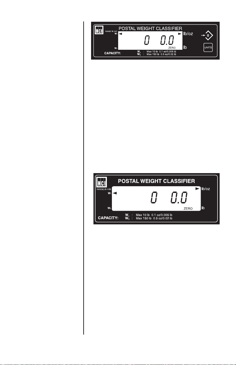
Model 7620 or 7680 Resident Display
Operational Controls
ZERO Key – The ZERO key will zero the scale if
weight is stable, functions as the NO or SCROLL
key in the Menu mode, and as the INCREASE
key in the Gravity mode.
UNITS Key – The UNITS key can be used to
change the scale unit of measure or to recall the
scale configuration information during the initial
power-up test sequence. This key also functions
as YES or ACCEPT in the Menu mode, and as
the DECREASE key in the Gravity mode.
Remote Display
All NCI 7600 bench scales can have an optional
remote display (shown above with no keyboard
function). If a remote display with keyboard is
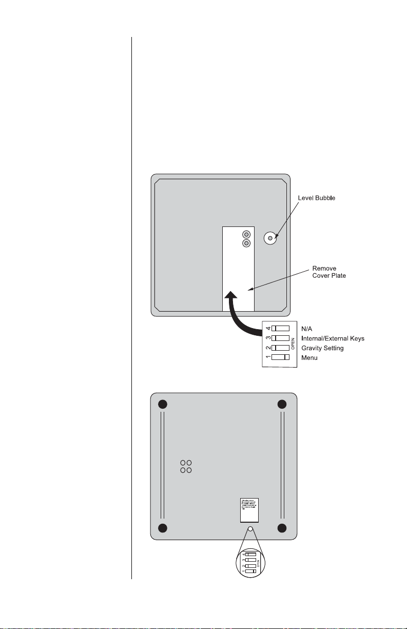
used, then Switch 3 (shown in Figure 1) determines which display keyboard is functional.
Switch 3 Settings
Closed= internal display keys operational
Open = external display keys operational
The remote display must be connected to the
RJ45 port (“DISPLAY”) on power up to operate
properly.
Model 7600 Family PWC User’s Manual
11
Page 12
Accessing the
Menu Mode
The 7600 family powers up in normal weighing
mode ready for weighing operations. You can
access the Menu mode by setting Switch 1
shown in Figure 1 to the OPEN or Menu mode
position.
Accessing the Gravity
Setting Mode
Figure 1
7620 Switch Location
Bottom View
of Model 7680
Access the Gravity setting mode by setting
Switch 2 shown in Figure 1 to the OPEN or
Gravity mode position.
12
Model 7600 Family PWC User’s Manual
Page 13

Menu Mode
There are four modes available to you with
Switch 1 in the Menu mode or OPEN position.
They are as follows:
1. DIAG Mode – To test areas of the scale’s
function
2. CONFIG Mode – To configure your scale for
your application
3. CAL Mode – To calibrate the scale
4. Re-CAL Mode – To change specific calibra-
tion parameters without having to re-calibrate
the scale.
Gravity Mode
With Switch 2 in the Gravity mode or OPEN
position, you may increase the “Local” gravity
value by pressing the ZERO key or decrease the
value by pressing the UNITS key.
The structure for these menus is shown in Figure
2. Specific information about each mode and
step-by-step instructions for accessing them
follow.
Model 7600 Family PWC User’s Manual
13
Page 14

Figure 2
7600 Menu Structure
14
Notes:
(1) The ‘re-calibration values displayed will be the same
as those of the original ‘calibration units of measure.
(2) Will flash “can’t” if originally calibrated for a non-
switching kg capacity/resolution.
(3) Will flash can’t if originally calibrated for a non-
switching lb capacity/resolution.
(4) To change the ‘Local’ gravity setting, press (and hold)
the ZERO key to increase the value, or press (and
hold) the TEST key to decrease the value. When
done, set Switch 2 back to the CLOSED position.
Model 7600 Family PWC User’s Manual
Page 15

7600 Menu Structure - Glossary
Table 1
Table 2
Table 3
30 Calibrates your scale for 30 kilogram
capacity.
50L Calibrates your scale for 50 kilogram
capacity, low resolution.
50H Calibrates your scale for 50 kilogram
capacity, high resolution.
75 Calibrates your scale for 75 kilogram
capacity.
70 Calibrates your scale for 70 pound
capacity.
100L Calibrates your scale for 100 pound
capacity, low resolution.
100H Calibrates your scale for 100 pound
capacity, high resolution.
150 Calibrates your scale for 150 pound
capacity.
Unit on Choosing this option enables the
units key. The units key allows you to
switch between the chosen modes of
measurement during calibration.
Unit Off Choosing this option disables the
units key.
Model 7600 Family PWC User’s Manual
15
Page 16

Table 4
lb kg With "unit on" option enabled,
pressing the UNITS key switches
between decimal pounds and
kilograms.
lb-oz kg With "unit on" option enabled,
pressing the UNITS key switches
between pounds- ounces and
kilograms.
lb-oz lb With "unit on" option enabled,
pressing the UNITS key switches
between pounds- ounces and
decimal pounds.
1000 g With "unit off" option enabled, the
scale displays weight in kilograms
when calibrated for Kg.
lb ounce With "unit off" option enabled, the
scale displays weight as pound/
ounce when calibrated as a scale or
classifier. Example: (1 lb .05 oz)
Dec lb With "unit off" option enabled, the
scale displays weight in decimal
pounds when calibrated as a scale or
classifier.
16
Model 7600 Family PWC User’s Manual
Page 17

Table 5
RNG ON Choosing this function activates the
multi-ranging function of the scale.
Display returns to higher resolution
mode only after returning to a stable
zero (0.00). For TYPE APPROVED
applications.
RNG OFF Choosing this function places the
scale in the high resolution through
capacity of the scale. For NONTYPE APPROVED applications only.
INT ON Choosing this function activates the
multi-interval function of the scale.
Display returns to higher resolution
mode immediately at multi-ranging
weight value. For TYPE APPROVED
applications.
Alternate Span
Calibration Points
Table 6
The NCI 7600 bench scales allow calibration
using less than full capacity weights. Below are
the alternative weights that can be used to
calibrate your scale for its designated capacity.
Alternative Span
Capacity Calibration Weights
lbs
70 10/50/70
100 10/50/100
150 10/50/150
kgs
30 10/20/30
50 10/25/50
75 10/50/75
Model 7600 Family PWC User’s Manual
17
Page 18

Diagnostics Mode
Diagnostics (DIAG )
Mode
The Diagnostic (Diag) mode menu lets you test
specific areas of the scale’s function.
These areas are:
Display (DISPLAY) – Shows the version and
revision of the software, followed by a display
segment test.
RAM (RA) – Performs a nondestructive test of
RAM in the processor. Displays PASS or FAIL.
ROM (RO) – Performs a checksum of all locations in ROM in the processor. Displays PASS or
FAIL.
Input/Output (I-O) – Data is output by the scale
and through the use of a loopback connector the
data is immediately read back into the receive
channel and verified against what was sent.
PASS or FAIL is displayed. Requires a jumper
(short) between transmit (Pin 2) and receive (Pin
3) data lines.
Division, test w/AZT (DIV-A) – Weight data is
normalized to 1,000,000 counts of displayed
resolution. AZT is enabled (Auto Zero Tracking).
18
Division, test w/o / AZT (DIV-N) – Weight data
is normalized to 1,000,000 counts of displayed
resolution. AZT is disabled.
Raw Counts (RA CNTS) – Non-normalized QDT
cell data (no zero tracking).
Model 7600 Family PWC User’s Manual
Page 19

Step-by-Step Instruc-
tions for DIAG Mode
Press the ZERO key to
scroll through lists of
selections.
Press the UNITS key
to make a selection
Follow these steps to access the tests in the
DIAG menu (Refer to Figure 2).
1. From normal weighing mode, move Switch 1
to the Menu mode or OPEN position.
DIAG is displayed.
2. Press the UNITS key…
DISPLAY is displayed.
3. Press the UNITS key to perform the display
test described earlier…
Display test is performed and shows
DISPLAY after the test is completed.
4. Press the ZERO key…
RA is displayed. This stands for the RAM
test.
5. Press the UNITS key to perform the RAM
test…
PASS or FAIL is displayed briefly. If the
test fails, the unit may have a RAM
memory failure. Try the test a second
time and if FAIL is displayed, contact
your local Weigh-Tronix dealer for
service.
6. Press the ZERO key…
RO is displayed. This stands for the
ROM test.
7. Press the UNITS key to perform the ROM
test…
PASS or FAIL is displayed briefly. If the
test fails, the unit may have a program
memory failure. Try the test second time,
and if FAIL is displayed, contact your
local Weigh-Tronix dealer for service.
Model 7600 Family PWC User’s Manual
19
Page 20

8. Press the ZERO key…
I-O is displayed. This stands for the
Input/Output test.
9. With a loopback connector in place, press
the UNITS key to perform the I/O test…
PASS or FAIL is displayed. If the test
fails, the unit may have a serial interface
failure. Check your connections and/or
contact your local Weigh-Tronix dealer
for service.
10. Press the ZERO key…
DIV-A is displayed. This stands for the
high resolution test with AZT enabled.
11. Press the UNITS key to perform this test…
The display shows the weight on the
scale at a resolution of 1,000,000 counts.
DIAG will flash every
10 seconds during the
high resolution test to
remind you that you
are doing a test and
not seeing normal
weight readings.
20
12. Press the UNITS key to stop the test…
13. Press the ZERO key…
DIV-N is displayed. This stands for the
high resolution test without AZT enabled.
14. Press the UNITS key to perform this test…
The display shows the weight on the
scale at a resolution of 1,000,000 counts.
15. Press the UNITS key to stop the test…
16. Press the ZERO key…
RA CNTS is displayed. This stands for
raw counts.
17. Press the UNITS key to perform this test…
The display shows non normalized cell
data.
Model 7600 Family PWC User’s Manual
Page 21

18. Press the UNITS key to stop the test.
19. When you are finished with the test, press
the ZERO key, until DONE is displayed.
Press the UNITS key, or place Switch 1 back
to normal mode to return to normal weighing
mode.
Configuration Mode
Configuration (CONFIG)
Mode
The Configuration (CONFIG) mode menu lets
you configure your scale to your specific application needs. The items you can configure are as
follows:
Filter (FILTER) – Choose from FLTR ON OR
FLTR OFF. Default is FLTR ON. In a stable,
vibration free location, the FLTR OFF setting
could be used if quicker display response is
desired.
Baud (BAUD) – Choose one of the following
baud rates: 1200, 2400, 4800, 9600, and 19200.
Default is 9600.
Parity (PARITY) – Choose from: NONE, EVEN,
or ODD. Default is EVEN.
Protocol (Prot) – Choose communication
protocol: NCI STD for standard NCI protocol, NCI
SMA for Scale Manufacturers’ Association
Standard for Scale Serial Communications,
AS350d for Detecto emulation, or PS6L for
Mettler emulation. Default is NCI STD.
Model 7600 Family PWC User’s Manual
21
Page 22

Step-by-Step
Instructions for
CONFIG Mode
Follow these steps to access and configure the
items in the CONFIG menu. Refer to Figure 2.
1. From the DIAG display press the ZERO key,
or from normal weighing mode, move Switch
1 to Menu mode or OPEN position, then
press the ZERO key…
CONFIG is displayed.
Press the ZERO key to
scroll through lists of
selections.
Press the UNITS key
to make a selection
Tip: Quickly and easily
view current scale
configuration directly
from the front panel
without opening the
scale or setting
switches as follows:
During the display
segment test on
power-up, press the
UNITS key. The
display will prompt
ABORT followed
by BAUD. Press the
ZERO key to scroll
through the choices, or
press the UNITS
key to view a current
scale configuration.
When you are done,
press the ZERO key
until DONE is displayed. Press the
UNITS key to return to
the normal weighing
mode.
2. Press the UNITS key…
FILTER is displayed.
3. Press the UNITS key…
The current setting is displayed. Use the
ZERO key to toggle between FLTR ON
and FLTR OFF
4. Press the UNITS key…
Filter selection is stored.
5. Press the ZERO key…
BAUD is displayed.
6. Press the UNITS key…
The current setting is displayed. Use the
ZERO key to toggle between the five
choices: 1200, 2400, 4800, 9600, or
19200 baud
7. Press the UNITS key…
Baud rate selection is stored.
8. Press the ZERO key…
PARITY is displayed.
9. Press the UNITS key…
The current setting is displayed. Use the
ZERO key to toggle between the three
choices: EVEN, ODD, NONE.
22
Model 7600 Family PWC User’s Manual
Page 23

10. Press the UNITS key.
Parity selection is stored.
11. Press the ZERO key…
PROT is displayed.
12. Press the UNITS key…
The current setting is displayed. Use the
ZERO key to toggle between the four
choices: NCI STD, NCI SMA, AS350D,
PS6L.
13. Press the UNITS key…
Protocol selection is stored.
14. When finished configuring your scale, press
the ZERO key until the display shows DONE,
then press the UNITS key.
Or, move Switch 1 to CLOSED position for
normal weighing mode.
Calibration Mode
Calibration (CAL) Mode
Warning! Entering into
this mode can erase
the calibration already
saved. You need
approved calibration
weights to use
calibration mode.
Note: If this procedure
is attempted without
proper calibration
weights applied, the
scale will abort the
process and retain the
original calibration
data.
The calibration (CAL) mode menu lets you
calibrate your scale. The items in the calibration
menu are as follows:
Pounds/Kilograms (LB or 1000g)
Scale or Classifier
Model 7600 Family PWC User’s Manual
Selects the unit of measure of your calibration test weights.
When calibrating the scale for LB, you are
able to calibrate the unit as a scale or as a
classifier (weight classifier).
23
Page 24

Unit On or Unit Off
When configured for UNIT ON, the scale will
allow you to switch between the selected
units of measure using the UNITS key.
Capacity (100, etc.)
Select the capacity of your scale.
Step -by-Step
Instructions for
CAL Mode
Follow these steps to calibrate your scale. Refer
to Figure 2.
1. From normal weighing mode, move Switch 1
to the Menu Mode or OPEN position…
DIAG is displayed. Press the ZERO key
until CAL is displayed. This stands for
calibration.
2. Press the UNITS key to start calibration…
LBS or 1000g (kg) is displayed.
3. Press the ZERO key to toggle between the
choices of units of measure (lb or kg). When
the choice you want is displayed, press the
UNITS key to accept…
If LBS was chosen for calibration, the
scale will display the current setting.
Press the ZERO key to toggle between
SCALE and CLASSIFIER. Calibrating as
SCALE = .5 division rounding. Calibrating
as CLASSIFIER = .9 division rounding.
Press UNITS key to accept.
24
4. The current capacity is displayed. Press the
ZERO key to toggle between scale capacity
selections. Press the UNITS key to accept…
That choice is accepted and UNIT ON or
UNIT OFF is displayed.
Model 7600 Family PWC User’s Manual
Page 25

Close Switch 1 or
unplug scale NOW if
you don’t have correct
calibration weights.
5. Press the ZERO key to toggle between the
choices UNIT ON or UNIT OFF. Once your
choice is displayed, press the UNITS key…
See above for the definitions of calibrating the scale using UNIT ON or UNIT
OFF.
6. Press the ZERO key to toggle between the
choices. When the choice you want is
displayed, press the UNITS key…
The scale prompts RNG ON, INT ON, or
RNG OFF. See Table 5 in 7600 Menu
Structure - Glossary, for definitions of
multi-range functions.
7. Press the ZERO key to toggle between
choices.
8. Press the UNITS key to accept…
The scale then prompts LOAD O.
9. Clear all weight from the scale platter and
press the UNITS key…
After a brief wait LOAD 100 (span
weight) is displayed. Alternate calibration
points can be chosen using the ZERO
key to toggle between choices. See
Table 6 in 7600 Menu Structure - Glos-
sary,
10. Place chosen (alternate) calibration weight
on the scale and press the UNITS key…
After a brief wait, DONE is displayed.
The scale then displays CAL.
11. Remove the calibration weight and return
Switch 1 to the closed position…
The scale returns to normal weighing
mode.
The scale is now tested, configured and calibrated. It is ready for use in your application.
Model 7600 Family PWC User’s Manual
25
Page 26

Re-Calibration
Re-Calibration
(RE-CAL) Mode
Step-by-Step
Instructions
for RE-CAL mode
The re-calibration RE-CAL mode menu lets you
change the scale resolution, rounding method,
units and range or interval method without using
any calibration weights.
For a scale originally calibrated in the lb mode,
you may also change rounding methods (i.e.
scale or classifier).
Follow these steps to re-configure your scale
(without weights). Refer to Figure 2.
1. From the normal weighing mode, move
Switch 1 to the Menu mode or Open position…
DIAG is displayed.
2. Press the ZERO key until…
RE-CAL is displayed.
3. Press the UNITS key…
ROUND is displayed.
Can’t will be displayed
if originally calibrated
for a non-switching
capacity/resolution.
26
To change the weight rounding method,
press the UNITS key. The current
rounding method is displayed.
4. Press the ZERO key to toggle between
SCALE and CLASS.
5. When the choice you want is displayed,
press the UNITS key.
6. To change the capacity/resolution, press the
ZERO key until RESO is displayed.
Model 7600 Family PWC User’s Manual
Page 27

7. Press the UNITS key. The current capacity/
resolution setting is displayed.
8. Press the ZERO key until desired capacity/
resolution is displayed.
9. Press the UNITS key to select a new
capacity/resolution.
10. Press the ZERO key…
UNITS is displayed. To change the
UNITS key status or the current unit of
measure, press the UNITS key, the
current choice is displayed.
11. Press the ZERO key to toggle between UNIT
ON and UNIT OFF.
12. Press the UNITS key to select the UNITS key
status and to display unit selections. To
change units, press the ZERO key to toggle
between the choices.
13. When the choice you want is displayed,
press the UNITS key.
14. Press the ZERO key…
RNG-INT is displayed. To change
RANGE operation, press the UNITS key.
The current setting is displayed.
15. Press the ZERO key to toggle between RNG
ON and RNG OFF or INT ON.
Model 7600 Family PWC User’s Manual
27
Page 28

Gravity Mode
16. When the choice you want is displayed,
press the UNITS key.
17. Press the ZERO key.. .
DONE is displayed.
18. Close Switch 1 to return to normal weighing
mode.
The CAL-GR and
LOC-GR values may
be viewed anytime.
See Review Scale
Setting section.
Using this feature in
sealed applications
may be subject to
approval by the
appropriate governing
agency at the endusers site.
Gravity value roles
‘over’ at 9.8400 and
rolls ‘under’ at 9.7700.
The Gravity mode feature provides a means of
adjusting the scale’s internal calibration factors to
compensate for variations in acceleration due to
gravity at different geographic locations. These
differences can cause a given mass to indicate a
slightly different weight at an end-user’s (local)
site than it did at the Calibration (CAL) site.
To make the adjustment, you must know the
value of the gravity constant for the local site.
This value is expressed in meters per second,
per second (i.e., m/s2). It is not necessary to
calibrate the scale, therefore, no calibration
weights are needed to make this adjustment.
The scale maintains two gravity setting values.
The first is the “calibration-site” value known as
CAL-GR. The second is the end-user or “localsite” value and is known as LOC-Gr. When the
scale was originally calibrated at the factory, the
CAL-GR and LOC-GR values were both set to
9.8040 which is the gravity constant for the
manufacturing site.
To adjust the displayed weight value, you must
enter the local gravity value.
28
Model 7600 Family PWC User’s Manual
Page 29

To enter the Gravity mode, set Switch 2 to the
OPEN position. The display will indicate the
current “local” gravity value. Press the ZERO key
to increment the value or the UNITS key to
decrement the value. The gravity value will
change in steps of .0001. When the correct value
is displayed, simply return Switch 2 to the
CLOSED position. The scale will now use this
new relationship between calibration and local
gravity for its weight calculations.
When the scale is calibrated using calibration
weights, the CAL-GR value is automatically set
equal to the LOC-GR setting. Therefore, it is
recommended that you verify the local gravity
setting is accurate before doing a full calibration.
Model 7600 Family PWC User’s Manual
29
Page 30

Review Scale Settings
Press the ZERO key to
move to the next item
in the menu.
Press the UNITS key
to select the display
item to view.
Pushing the UNITS key during the segment test
on power-up, will allow you to view current scale
setup.
30
When finished viewing the settings, press the
ZERO key until DONE is displayed. Then press
the UNITS key to return to normal weighing
mode of operation.
Model 7600 Family PWC User’s Manual
Page 31

Communications
The NCI 7600 family scales come factory configured as a serial RS-232 interface device. There
is one 9-pin DE type female connector accessible
at the rear of the unit. The functional pinout of
this connector is compatible with a standard PC
pass-through cable.
Interface Cable
* Jmp1 and Jmp2 pins
are connected
internally on the scale
PCB connector.
NCI STD
Communications
Protocol
DE-9 Female Scale DE-9 Male Host
Pin Name Direction Pin Name Direction
1. JMP 1 - 1. DCD IN
2. TXD OUT 2. RXD IN
3. RXD IN 3. TXD OUT
4. JMP 1 - 4. DTR OUT
5. SGND - 5. GND -
6. JMP 1 - 6. DSR IN
7. JMP 2 - 7. RTS OUT
8. JMP 2 - 8. CTS IN
9. NC - 9. RI IN
The scale uses a DE-9 connector.
This standard is used by all NCI bench scale
products.
Symbol key:
<ETX> End of Text character (03
hexadecimal).
<LF> Line Feed character (0A hex).
<CR> Carriage Return character (0D hex).
<SP> Space (20 hex).
x Character from display including
minus sign.
hhh Three status bytes.
uu Unit of measure using ANSI standard
abbreviations
Model 7600 Family PWC User’s Manual
31
Page 32

Standard
Commands
Optional
Commands
Hi Resolution
Weight
Status
Zero
W<CR>
Scale Response
<LF>xxxx.xxuu<CR>
<LF>hhh <CR><ETX> Returns decimal lb
or kg weight, units
and scale status
or
<LF>xx lb<sp>xx.x oz<CR>
<LF> hhh <CR> <ETX> Returns lb-oz
weight, units and
scale status
S<CR>
Scale Response
<LF>hhh <CR><ETX> Returns scale
status
Z<CR>
Scale Response
<LF>hhh <CR><ETX> Scale is zeroed,
returns status
H<CR>
Scale Response
<LF>xxxx.xxxuu<CR>
<LF>hhh <CR><ETX> Returns decimal lb
or kg weight in 10X
format with units
or and scale status
32
<LF>xx lb<sp>xx.xx oz<CR>
<LF>hhh<CR><ETX> Returns lb-oz
Units
U <CR>
Scale Response
<LF> uu <CR>
<LF> hhh<CR><ETX> Changes unit of
Model 7600 Family PWC User’s Manual
weight in 10X
format with units
and scale status
measure and
returns new unit
and status
Page 33

Raw Counts
M<CR>
Scale Response
<LF>xxxxxxxMM<CR>
<LF>hhh <CR><ETX> Returns normalized
raw counts and
status
All other commands
Scale Response
<LF>?<CR><ETX> Unrecognized
command
NCI SMA, AS350D or
PS6L Communications
Protocol
Error Codes
Contact your Weigh-Tronix service provider or
the Weigh-Tronix customer service department
for protocol.
Any system errors detected by the scale will be
displayed as the letter E followed by a two-digit
error code. Press the UNITS key to continue
operation. If a calibration error occurs, the only
way to clear it is by recalibrating the scale.
The error codes are broken down into two
hexadecimal numbers, with each bit defining a
single error condition. The error codes are
defined as follows:
Model 7600 Family PWC User’s Manual
33
Page 34

Troubleshooting
Perform the following steps in the order presented until the described problem is corrected. If
the problem cannot be corrected, contact an
authorized Weigh-Tronix service provider.
No Power (Display is Blank)
1. Check that the primary side of the cord is
plugged into the AC outlet, and the secondary side is properly connected to the power
jack on the back of the scale.
2. Replace the power supply.
3. Replace the display board.
4. Replace the I/O board.
5. Replace the QDT load cell.
Missing or extra segments on display
1. Replace the display board.
2. Replace the QDT load cell.
34
Model 7600 Family PWC User’s Manual
Page 35

Scale will not return to zero, or incorrect
weight is displayed
1. Press the ZERO key.
2. Check for interference of weighing platform.
3. Power off, remove all items from the platter,
and then power on the scale.
4. Recalibrate the scale.
5. Replace the QDT load cell.
Display shows unrecognized characters
1. Check software PROM for proper insertion.
2. Check display cables for the proper connection.
3. Replace the display board.
4. Replace PROM.
5. Replace the QDT load cell.
Display shows under “_ _ _ _” dashes
(Indicates that the scale is below zero or under
capacity.)
1. Verify that weigh platter is on the scale.
2. Press the ZERO key.
3. Power off, remove any items from the platter,
and then power on the scale.
4. Recalibrate the scale.
5. Replace the QDT load cell.
Display shows center “
_ _ _ _
” dashes
(Indicates that the scale is outside zero capacity
of ±2%.)
1. Verify that weigh platter is on the scale.
2. Press the ZERO key.
3. Power off, remove any items from the platter,
and then power on the scale.
4. Recalibrate the scale.
5. Replace the QDT load cell.
Model 7600 Family PWC User’s Manual
35
Page 36

Display shows upper “
_ _ _ _
“ dashes
(Indicates the scale is over capacity.)
1. Remove all items from the scale.
2. Press the ZERO key.
3. Power off, and then power on the scale.
4. Recalibrate the scale.
5. Replace the QDT load cell.
Scale is not transmitting data to the host
device
1. Check cable connection at both the rear
of the scale and the host device.
2. Check communication setting and baud
rate on both the scale and host device.
3. Perform I/O loopback test.
4. Replace the cable.
5. Replace the I/O board.
6. Replace the QDT load cell.
36
The ZERO key and the UNITS key do no
function
1. Check the position of Switch 3. Closed for
internal display keypad active. Open for
external display keypad active.
2. Open display enclosure and verify that the
keypad cable is still installed correctly.
3. Replace the display panel.
4. Replace the display PCB.
5. Replace the display cable.
6. Replace the I/O PCB.
7. Replace the QDT load cell.
Model 7600 Family PWC User’s Manual
Page 37

Spare Parts Listing
DESCRIPTION PART NUMBER
Keyboard Panel 1163-13198
Display PCB 7405-15990-01
I/O PCB 7405-15550-02
Power Supply -115 VAC 1148-15536
Power Supply - 230 VAC 1148-15833
RS-232 Cable 1140-13842
Load Cell 70 lb 7153-15694-23
Load Cell 100 lb 7153-15694-50
Load Cell 150 lb 7620 7153-15694-80
7620 Feet 7075-15475-02
Shroud ABS Plastic 7620 1076-15256
Shroud SS 7620 1076-15767
Shroud Ball-top (BTS) 7620 7200-15145
Load Cell 150 lb 7680 7153-15694-110
Shroud SS 7680 1076-15050
Shroud BTS Kit 7680 7200-15196
7680 Feet 7075-13082
Model 7600 Family PWC User’s Manual
37
Page 38

38
Model 7600 Family PWC User’s Manual
Page 39

Model 7600 Family PWC User’s Manual
39
Page 40

1000 Armstrong Drive
Fairmont, MN 56031
T elephone: 507-238-4461
Facsimile: 507-238-4195
E-Mail: service@wt-nci.com
www .wt-nci.com
 Loading...