

Page 1
OPERATOR’S MANUAL
MANUEL D’UTILISATION
AUTO POWER OFF
MODE
RANGE
REL
MANUAL DEL OPERADOR
V
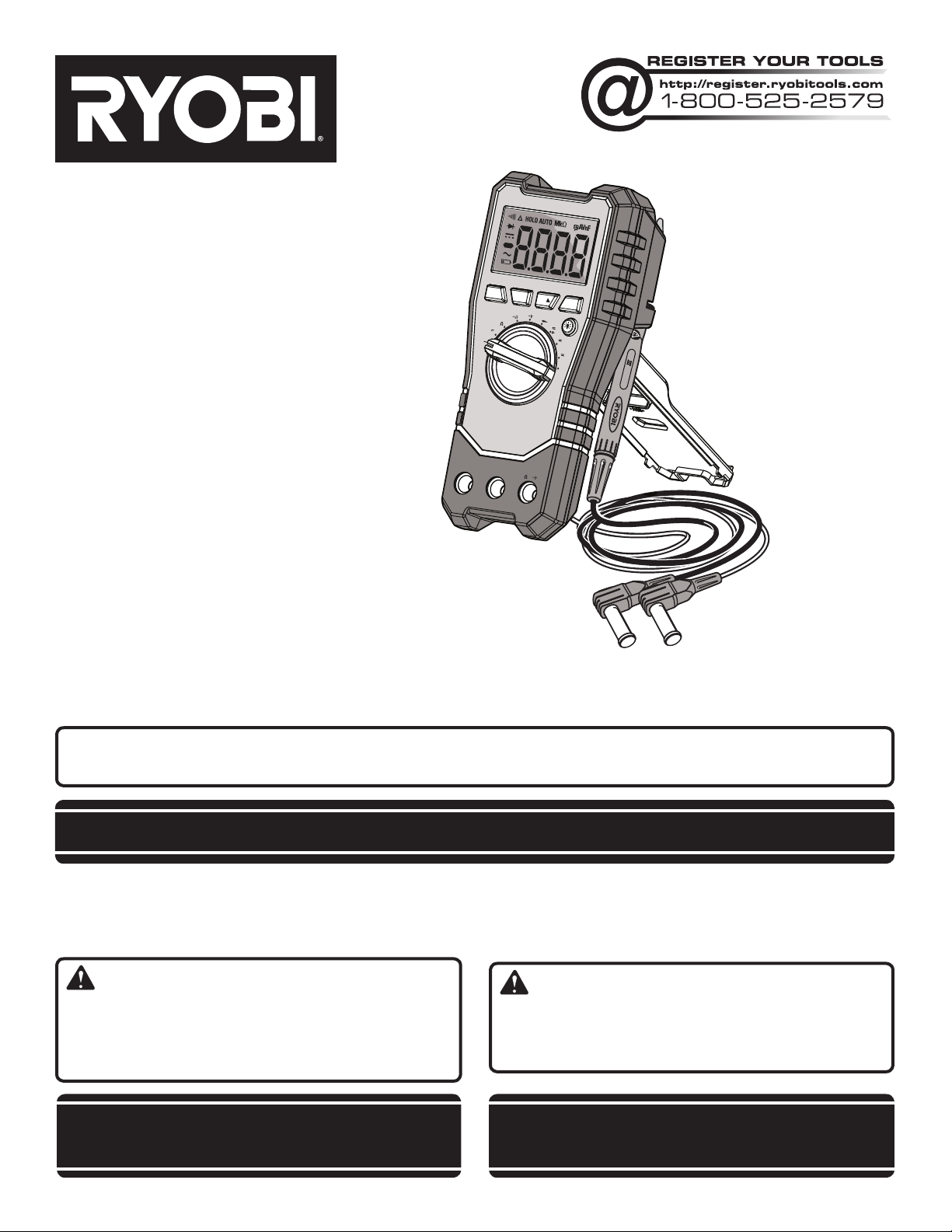
Tek4® DIGITAL MULTIMETER
MULTIMÈTRE NUMÉRIQUE
MULTÍMETRO DIGITAL
RP4020
Your multimeter has been engineered and manufactured to our high standard for dependability, ease of operation, and
operator safety. When properly cared for, it will give you years of rugged, trouble-free performance.
V
OFF
10A
COM
HOLD
I
I
A
mA
A
OFF
V I
CAT 600V 10A
CAUTION: To reduce the risk of injury or property damage, the user must read and understand the operator’s manual before
using this product. If you do not understand the warnings and instructions in the operator’s manual, do not use this product.
SAVE THIS MANUAL FOR FUTURE REFERENCE
Cette multimètre a été conçu et fabriqué conformément à nos strictes
normes de fiabilité, simplicité d’emploi et sécurité d’utilisation.
Correctement entretenu, cet outil vous donnera des années de
fonctionnement robuste et sans problème.
AVERTISSEMENT : Pour réduire les risques de
blessures, l’utilisateur doit lire et veiller à bien comprendre
le manuel d’utilisation avant d’employer ce produit. Si tous
les avertissements et toutes les consignes de sécurités et
instructions du manuel d’utilisation ne sont pas bien compris,
ne pas utiliser ce produit.
CONSERVER CE MANUEL POUR
FUTURE RÉFÉRENCE
Su multímetro ha sido diseñado y fabricado de conformidad
con nuestras estrictas normas para brindar fiabilidad, facilidad
de uso y seguridad para el operador. Con el debido cuidado, le
brindará muchos años de sólido funcionamiento y sin problemas.
ADVERTENCIA: Para reducir el riesgo de lesiones,
el usuario debe leer y comprender el manual del operador antes
de usar este producto. Guarde este manual del operador y
estúdielo frecuentemente para lograr un funcionamiento seguro
y continuo de este producto.
GUARDE ESTE MANUAL PARA
FUTURAS CONSULTAS
Page 2

TABLE OF CONTENTS
Introduction ..................................................................................................................................................................... 2
Warranty .......................................................................................................................................................................... 2
General Safety Rules .................................................................................................................................................... 3-4
Specific Safety Rules .................................................................................................................................................... 4-5
Symbols ........................................................................................................................................................................... 6
Features ........................................................................................................................................................................... 7
Assembly ......................................................................................................................................................................... 8
Operation .................................................................................................................................................................... 8-12
Maintenance .................................................................................................................................................................. 13
Figure numbers (illustrations) ........................................................................................................................................ 14
Parts Ordering / Service ................................................................................................................................... Back page
INTRODUCTION
This product has many features for making its use more pleasant and enjoyable. Safety, performance, and dependability
have been given top priority in the design of this product making it easy to maintain and operate.
WARRANTY
LIMITED TWO YEAR WARRANTY AND 90 DAY EXCHANGE POLICY
90-DAY EXCHANGE POLICY: During the first 90 days after date of purchasing this product, you may either request service
under this warranty or you may exchange it by returning it with proof of purchase and all original equipment packaged with
the original product to the dealer from which it was purchased. The replacement product will be covered by the limited
warranty for the balance of the two year period from the date of the original purchase.
LIMITED TWO YEAR WARRANTY. This product is warranted against all defects in workmanship or materials for a period
of two years from the date of purchase. The warranty on any accessories for this product, excluding batteries, is limited to
90 days from the date the accessory is purchased. To obtain warranty service, call Customer Service at 1-800-525-2579
for warranty return instructions. The product must be properly packaged and returned with all equipment that was included
with the original product. When you request warranty service, you must also present proof of purchase documentation,
which includes the date of purchase (for example, a receipt or a bill of sale). Defective products returned within the warranty period will be repaired or replaced, at our option, free of charge, within ninety (90) days or less. The cost of shipping
the product to us is your responsibility. This warranty only covers defects arising under normal usage and does not cover
any malfunction, failure or defects resulting from misuse, abuse, neglect, alteration, modification or unauthorized repairs.
It applies only to the original purchaser at retail, and may not be transferred. One World Technologies, Inc. makes no warranties, representations or promises as to the quality or performance of this product other than those specifically stated
in this warranty. Any implied warranties granted under state law, including warranties of merchantability or fitness for a
particular purpose, are limited to two years from the date of purchase. One World Technologies, Inc. is not responsible for
direct, indirect, or incidental damages Some states do not allow limitations on how long an implied warranty lasts, or the
exclusion or limitation of incidental or consequential damages, so the above limitations and exclusions may not apply to
you. This warranty gives you specific legal rights, and you may also have other rights which vary from state to state.
2 – English
Page 3

GENERAL SAFETY RULES
WARNING -
Read all instructions. Failure to follow all instructions
listed below may result in electric shock, fire and/or
serious injury. To reduce the risk of injury, user must read
instruction manual.
SAVE THESE INSTRUCTIONS
Keep work area clean and well lit. Cluttered or dark
areas invite accidents.
Avoid body contact with earthed or grounded surfaces
such as pipes, radiators, ranges and refrigerators.
There is an increased risk of electric shock if your body
is earthed or grounded.
Do not expose battery products to rain or wet
conditions. Water entering a battery product will increase
the risk of electric shock.
Do not abuse the leads. Never use the leads for car-
rying or pulling the battery product. Keep leads away
from heat, oil, sharp edges or moving parts. Damaged
or entangled leads increase the risk of electric shock.
Use battery only with charger listed.
MODEL BATTERY PACK CHARGER
RP4020 AP4001 AP4700, AP4500
Stay alert, watch what you are doing and use common
sense when operating a battery product. Do not use
a battery product while you are tired or under the
influence of drugs, alcohol or medication. A moment
of inattention while operating battery products may result
in serious personal injury.
Do not overreach. Keep proper footing and balance at
all times. Do not use on a ladder or unstable support.
Stable footing on a solid surface enables better control
of the battery product in unexpected situations.
Maintain this product. Check breakage of parts and
any other condition that may affect the product’s
operation. If damaged, have the product repaired
before use. Many accidents are caused by poorly
maintained products.
Dress properly. Do not wear loose clothing or jewelry.
Keep your hair, clothing and gloves away from leads
or moving parts. Loose clothes, jewelry or long hair can
be caught in moving parts.
Wear rubber-bottomed shoes or sneakers when
working with high-voltage equipment. Make sure
that the controls applied will prevent operation of the
equipment and that all hazardous energy, including
residual or stored energy, is blocked, discharged, or
relieved prior to starting work.
If you need to probe or otherwise touch circuits with
power off, discharge (across) large power supply filter
capacitors (at least 2 times). Monitor while discharging
and/or verify that there is no residual charge using the
multimeter.
If you must probe live, put electrical tape over all
but the last 1/16 in. of the test probes to avoid the
possibility of an accidental short, which could cause
damage to various components. Clip the reference end
of the meter or scope to the appropriate ground return
so that you need to only probe with one hand.
Never enter alone into an area containing exposed
electrical energy sources.
Use only the test instruments and insulated tools
rated for the voltage and current specified.
Store idle battery products out of the reach of children
and do not allow persons unfamiliar with the battery
product or these instructions to operate the product.
Battery products are dangerous in the hands of untrained
users.
Maintain battery products. Check for misalignment
or binding of moving parts, breakage of parts and
any other condition that may affect the product’s
operation. If damaged, have the product repaired
before use. Many accidents are caused by poorly
maintained products.
Use the product and accessories in accordance with
these instructions and in the manner intended for the
particular type of product, taking into account the
working conditions and the work to be performed.
Use of the product for operations different from those
intended could result in a hazardous situation.
BATTERY PRODUCT USE AND CARE
Ensure the switch is in the OFF position before
inserting battery pack. Inserting the battery pack into
products that have the switch on invites accidents.
Recharge only with the charger specified by the
manufacturer. A charger that is suitable for one type
of battery pack may create a risk of fire when used with
another battery pack.
Use battery products only with specifically designated
battery packs. Use of any other battery packs may create
a risk of injury and fire.
When battery pack is not in use, keep it away from
other metal objects like paper clips, coins, keys, nails,
screws, or other small metal objects that can make a
connection from one terminal to another. Shorting the
battery terminals together may cause burns or a fire.
Under abusive conditions, liquid may be ejected from
the battery, avoid contact. If contact accidentally
occurs, flush with water. If liquid contacts eyes,
additionally seek medical help. Liquid ejected from the
battery may cause irritation or burns.
When servicing a battery product, use only identical
replacement parts. Follow instructions in the
Maintenance section of this manual. Use of unauthorized
parts or failure to follow Maintenance instructions may
create a risk of shock or injury.
Know your battery product. Read operator’s manual
carefully. Learn its applications and limitations, as
well as the specific potential hazards related to this
product. Following this rule will reduce the risk of electric
shock, fire, or serious injury.
3 – English
Page 4

GENERAL SAFETY RULES
Battery products do not have to be plugged into
an electrical outlet; therefore, they are always in
operating condition. Be aware of possible hazards
when not using your battery product or when changing
accessories. Following this rule will reduce the risk of
electric shock, fire, or serious personal injury.
Do not place battery products or their batteries near
fire or heat. This will reduce the risk of explosion and
possibly injury.
Do not crush, drop or damage battery pack. Do not
use a battery pack or charger that has been dropped
or received a sharp blow. A damaged battery is subject
SPECIFIC SAFETY RULES
Before you use the meter, inspect the case. Pay particular
attention to the insulation surrounding the connectors.
Inspect the test leads for damaged insulation or exposed
metal. Check the test leads for continuity. Replace
damaged test lead before you use the meter.
Do not use the meter if it operates abnormally. Protection
may be impaired. When in doubt, have the meter
serviced.
Do not operate the meter in a place where flammable or
explosive gas (or dust) is present.
Do not apply more than the rated voltage, as marked on
the meter, between terminals or between any terminal
and earth ground.
When measuring current, turn off circuit power before
connecting the meter in the circuit. Remember to place
the meter in series with the circuit.
Use caution when working above 30V AC rms, 42V peak,
or 60V DC. Such voltages pose a shock hazard.
When using the probes, keep your fingers behind the
finger guards on the probes.
When making connections, connect the common test
lead before you connect the live test lead.
When you disconnect test leads, disconnect the live test
lead first.
Remove all test leads from the meter before you open
the battery cover or portion of the case.
Do not operate the multimeter with the battery door or
portions of the case loosened or removed.The battery
door should be securely closed before operating the
multimeter.
To avoid false readings, which could lead to possible
electric shock or personal injury, replace or charge the
battery as soon as the low battery indicator (
appears.
Use the meter only as specified in this manual; otherwise
the safety features of the meter may be impaired.
to explosion. Properly dispose of a dropped or damaged
battery immediately.
Batteries can explode in the presence of a source
of ignition, such as a pilot light. To reduce the risk of
serious personal injury, never use any cordless product
in the presence of open flame. An exploded battery can
propel debris and chemicals. If exposed, flush with water
immediately.
For best results, your battery product should be
charged in a location where the temperature is more
than 50°F but less than 94°F. To reduce the risk of serious
personal injury, do not store outside or in vehicles.
When in Relative mode or in Data Hold mode, caution
must be used because hazardous voltage may be
present.
Do not electrically connect yourself to ground. Use
extreme caution because you may ground yourself if you
are careless.
Do not operate this meter if your hand or the meter is
wet.
Adhere to local and national safety codes.
Use Individual protective equipment to prevent shock and
arc blast injury when working in an area where hazardous
live conductors are exposed.
Remaining endangerment: When an input terminal is
connected to dangerous live potential, it is to be noted
that this potential at all other terminals can occur!
CATIII - Measurement category III is for measurements
performed in the building installation. Examples are
measurements on distribution boards, circuit breakers,
wiring, including cables, bus-bars, junction boxes,
switches, socket-outlets in the fixed installation, and
equipment for industrial use and some other equipment, for
example, stationary motors with permanent connection to
fixed installation. Do not use the meter for measurements
within Measurement Categories IV.
Use the proper terminals, function and range for your
measurements.
Before measuring current, check the meter’s fuses and
turn off power to the circuit before connecting the meter
to the circuit.
Before rotating the mode selection dial to change
functions, disconnect test leads from the circuit under
test.
Be sure the test leads and switch are in the correct
)
position for the desired measurement.
Never measure resistance in a circuit when power is
applied.
4 – English
Page 5
SPECIFIC SAFETY RULES
DECLARATION OF CONFORMITY
We declare under our sole responsibility that this product is in
conformity with the following standards or standardized documents.
2006/95/EC
EN61010-1:2001
EN61010-031:2002
DECLARATION OF CONFORMITY
We declare under our sole responsibility that this product is in
conformity with the following standards or standardized documents.
2006/95/EC
EN61010-1:2001
EN61010-031:2002
DECLARATION OF CONFORMITY
We declare under our sole responsibility that this product is in
conformity with the following standards or standardized documents.
2006/95/EC
EN61010-1:2001
EN61010-031:2002
Never touch the probes to a voltage source when the test
leads are plugged into the 10A or 400mA input.
Before use, verify the meter’s operation by measuring a
known voltage.
To avoid possible damage to the meter or to the equipment
under testing, follow these guidelines:
• Disconnect circuit power and discharge all high-voltage
capacitors before testing resistance, continuity, or
diodes.
• Before measuring current, check the meter’s fuses and
turn power OFF to the circuit before connecting the
meter to the circuit.
We declare under our sole responsibility that this product is in conformity with the following standards or
standardized documents.
DECLARATION OF CONFORMITY
Save these instructions. Refer to them frequently and
use them to instruct others who may use this product.
If you loan someone this product, loan them these
instructions also.
CALIFORNIA PROPOSITION 65
WARNING:
This product may contain chemicals, including lead,
known to the State of California to cause cancer, birth
defects, or other reproductive harm. Wash hands after
handling.
2006/95/EC
EN61010-1:2001
EN61010-031:2002
Machine: 4V Digital Multimeter Type: RP4020
Name of company: TECHTRONIC INDUSTRIES CO. LTD.
Address: 24/F, CDW BUILDING
388 CASTLE PEAK ROAD
TSUEN WAN
HONG KONG
Web: www.ttigroup.com
Trademarks:
The use of the trademark Ryobi is pursuant to a license granted by Ryobi Limited.
Name/Title: Brian Ellis
Vice President - Engineering
Signature:
5 – English
Page 6
SYMBOLS
The following signal words and meanings are intended to explain the levels of risk associated with this product.
SYMBOL SIGNAL MEANING
DANGER:
WARNING:
CAUTION:
CAUTION:
Some of the following symbols may be used on this product. Please study them and learn their meaning. Proper interpretation of these symbols will allow you to operate the product better and safer.
Indicates an imminently hazardous situation, which, if not avoided, will result
in death or serious injury.
Indicates a potentially hazardous situation, which, if not avoided, could result
in death or serious injury.
Indicates a potentially hazardous situation, which, if not avoided, may result in
minor or moderate injury.
(Without Safety Alert Symbol) Indicates a situation that may result in property
damage.
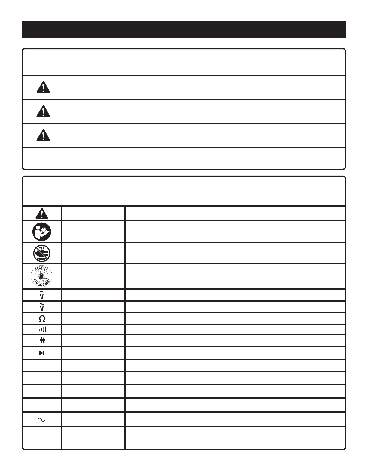
SYMBOL NAME DESIGNATION/EXPLANATION
Safety Alert Indicates a potential personal injury hazard.
Read The
Operator’s Manual
Wet Conditions
Alert
To reduce the risk of injury, user must read and understand operator’s manual
before using this product.
Do not expose to rain or use in damp locations.
This product uses lithium-ion (Li-ion) batteries. Local, state or federal laws may
Recycle Symbol
DC Volts Voltage
AC Volts Voltage
Ohms The unit of electrical resistance
Continuity Complete path for current flow
Capacitance Ability of a component to store an electrical charge
Diode A two electrode electron tube containing an anode and a cathode.
A Amperage The strength of an electric current expressed in amperes
Hz Hertz Frequency (cycles per second)
min Minutes Time
Direct Current Type or a characteristic of current
Alternating Current
.../min Per Minute Revolutions, strokes, surface speed, orbits etc., per minute
prohibit disposal of batteries in ordinary trash. Consult your local waste authority
for information regarding available recycling and/or disposal options.
Type of current
6 – English
Page 7

PRODUCT SPECIFICATIONS
FEATURES
Battery Voltage ................................................................4V
Display ....................................................... 3 3/4-digit LCD
Max. LCD reading ......................................................3999
Measurement category ............................................ CAT III
Maximum Voltage ........................................................600V
Maximum Current ......................................................... 10A
Sampling Rate .............................................. 2~3 times/sec
IP Rating ........................................................................ 54*
*IP Rating: Specifies the environmental protection the product enclosure provides. An IP Rating of 54 denotes protection against harmful
deposits of dust and protection against water sprayed from all directions. The water resistance rating applies only when the battery cap
is installed.
KNOW YOUR MULTIMETER
See Figures 1 - 3, page 14.
The safe use of this product requires an understanding of
the information on the product and in this operator’s manual.
Before use of this product, familiarize yourself with all operating features and safety rules.
This digital multimeter has been designed according to
IEC-61010 concerning electronic measuring instrument
with a measurement category III ( CAT III 600V ) and Pollution degree 2.
Operating Temperature................. 32°F - 94°F (0°C ~ 35°C),
<75%RH
Temperature Coefficient .......0.2 x (specified accuracy) / °F
(<64°F or 82°F)
0.2 x (specified accuracy) / °C
(<18°C or 28°C)
Storage Temperature ....................................... 14°F - 140
Operating Altitude ................................... 0 to 2000 meters
(-10°C ~ 60°C), <85%RH
°F
RANGE BUTTON
Switches the meter between autorange mode and manual
range mode, and also selects the desired manual range.
10A JACK
Plug-in connector for the red test lead for the current measurements between 400mA and 10A.
COM JACK
Plug-in connector for the black test lead for all measurements.
μA/mA JACK
DIGITAL LCD DISPLAY
The LCD display features easy to read digits for a variety
of functions.
MODE SELECTION DIAL
Used to select the desired function and turn the meter ON
or OFF.
BUILT IN PROBE STORAGE, KICK STAND,
AND CONVENIENCE HOOK
Keep the probes untangled, easily prop it up, and hang it
almost anywhere for one-handed operation
AUTO POWER OFF
The automatic power-off feature helps to conserve battery
power.
MODE BUTTON
Switches the meter between DC and AC current measurements.
Plug-in connector for the red test lead for all measurements
except the current measurements 400mA.
BACKLIGHT BUTTON
Turns the backlight on and off.
REL BUTTON
Used to enter Relative mode.
HOLD BUTTON
Used to enter Data Hold mode.
PROBE COVER STORAGE
When the black and red leads are in use, the probe covers
can be placed in the storage areas on the back of the unit.
ALLIGATOR CLIPS
Two covered alligator clips are included for securing the
probes to a circuit when you need to keep your hands
free.
7 – English
Page 8
ASSEMBLY
UNPACKING
This product has been shipped completely assembled.
Carefully remove the product and any accessories from
the box. Make sure that all items listed in the packing list
are included.
WARNING:
Do not use this product if it is not completely assembled
or if any parts appear to be missing or damaged. Use of
a product that is not properly and completely assembled
could result in serious personal injury.
Inspect the product carefully to make sure no breakage
or damage occurred during shipping.
Do not discard the packing material until you have care-
fully inspected and satisfactorily operated the product.
If any parts are damaged or missing, please call
1-800-525-2579 for assistance.
OPERATION
PACKING LIST
Multimeter
Leads/Probes
Alligator Clips
Operator’s Manual
WARNING:
If any parts are damaged or missing do not operate this
product until the parts are replaced. Use of this product
with damaged or missing parts could result in serious
personal injury.
WARNING:
Do not allow familiarity with products to make you careless. Remember that a careless fraction of a second is
sufficient to inflict serious injury.
WARNING:
Follow the General and Specific Safety Rules in this
manual when making electrical measurements and working with high voltages. Failure to follow standard safety
precautions could result in electric shock and serious
personal injury.
TO INSTALL/REMOVE THE BATTERY PACK
See Figure 2, page 14.
Make sure the mode selection dial is in the OFF position
before installing or removing the battery pack.
To remove the battery cover:
Use a small phillips screwdriver to loosen the screws and
remove the battery cover.
NOTE: The screws stay attached to the cover. There is
an o-ring in the slot in the housing. Make sure the o-ring
is fully seated in the slot.
Insert the battery pack in the direction shown.
Replace the battery compartment cover and reattach with
the screws.
Do not attempt to take readings unless the battery door
is securely closed.
8 – English
WARNING:
Always remove battery pack from your product when you
are assembling parts, making adjustments, cleaning, or
when not in use. Removing battery pack will prevent accidental starting that could cause serious personal injury.
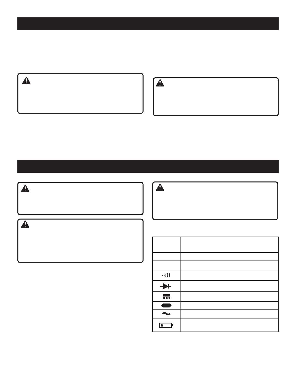
READING THE LCD DISPLAY
See Figure 3, page 14.
SYMBOL MEANING
AUTO
HOLD
Autorange mode is selected
Data hold is enabled
Relative mode is active
Continuity test is selected
Diode test is selected
DC
Negative sign
AC
Battery is low and should be recharged or
replaced immediately
Page 9
OPERATION
UNITS ON THE LCD DISPLAY
Voltage unit
mV, V
μA, mA,
A
Ω, k Ω,
MΩ
nF,
μF
mV: Millivolt ; V: Volt;
1V=103mV
Current unit
μA: Microamp; mA: Milliamp; A: Ampere;
1A=103mA=106μA
Resistance unit
Ω: Ohm; k Ω: Kilohm; MΩ: Megohm;
1M Ω =103k Ω =106 Ω
Capacitance unit
nF: Nanofarad; μF: Microfarad;
1F=106μF=109nF=1012pF
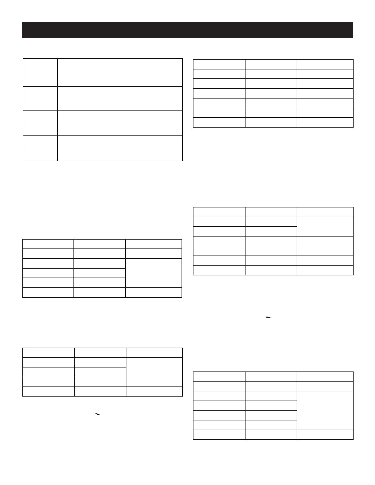
ACCURACY
Accuracy is specified for a period of one year after calibration
and at 64.4ºF to 82.4ºF (18ºC to 28ºC), with relative humidity < 75%. Except the ranges which are specified specially,
accuracy is specified from 8% to 100% of range.
Accuracy specifications take the form of:
± ([% of Reading]+[number of Least Significant Digits])
DC VOLTAGE
Range Resolution Accuracy
400mV 0.1mV ±(1.0%+5)
4V 0.001V
±(0.8%+3)40V 0.01V
400V 0.1V
600V 1V ±(1.0%+3)
Input Impedance: Range 400mV: >1000MΩ
The other ranges: 10MΩ
NOTE: The 600V range is specified from 20% to 100% of
range.
AC VOLTAGE
Range Resolution Accuracy
4V 0.001V
±(1.0%+5)40V 0.01V
400V 0.1V
600V 1V ±(1.2%+5)
Input Impedance: 10MΩ
Frequency Range: 40Hz 400 Hz
Response: Average, calibrated in rms of sine wave
NOTE: The 600V range is specified from 20% to 100% of
range.
DC CURRENT
Range Resolution Accuracy
400μA 0.1μA ±(1.2%+3)
4000μA 1μA ±(1.0%+3)
40mA 0.01mA ±(1.5%+3)
400mA 0.1mA ±(1.0%+3)
4A 0.001A ±(1.8%+3)
10A 0.01A ±(2.0%+5)
Overload Protection: Fuse 1: F 400mA, 690V
Fuse 2: F 10A, 600V/690V
Max. Input Current: 10A (For inputs > 2A : measurement
duration< 10 secs, interval >15 minutes)
Max. Measurement Voltage Drop: 200mV (for all DC current ranges except 10A range)
NOTE: The 10A range is specified from 20% to 100% of
range.
AC CURRENT
Range Resolution Accuracy
400μA 0.1μA
4000μA 1μA
40mA 0.01mA
400mA 0.1mA
4A 0.001A ±(2.0%+5)
10A 0.01A ±(2.5%+10)
Overload Protection: Fuse 1: F 400mA, 690V
Fuse 2: F 10A, 600V/690V
Max. Input Current: 10A (For inputs > 2A : measurement
duration < 10 sec, interval >15 minutes)
Frequency Range: 40Hz 400 Hz
Response: Average, calibrated in rms of sine wave
Max. Measurement Voltage Drop: 200mV (for all AC cur-
rent ranges except 10A range)
NOTE: The 10A range is specified from 20% to 100% of
range.
±(1.5%+5)
±(1.8%+5)
RESISTANCE
Range Resolution Accuracy
400Ω 0.1Ω ±(1.0%+5)
4kΩ 0.001kΩ
40kΩ 0.01kΩ
400kΩ 0.1kΩ
4MΩ 0.001MΩ
40MΩ 0.01MΩ ±(1.8%+5)
±(1.0%+3)
Overload Protection: 600V DC/AC rms
9 – English
Page 10
OPERATION
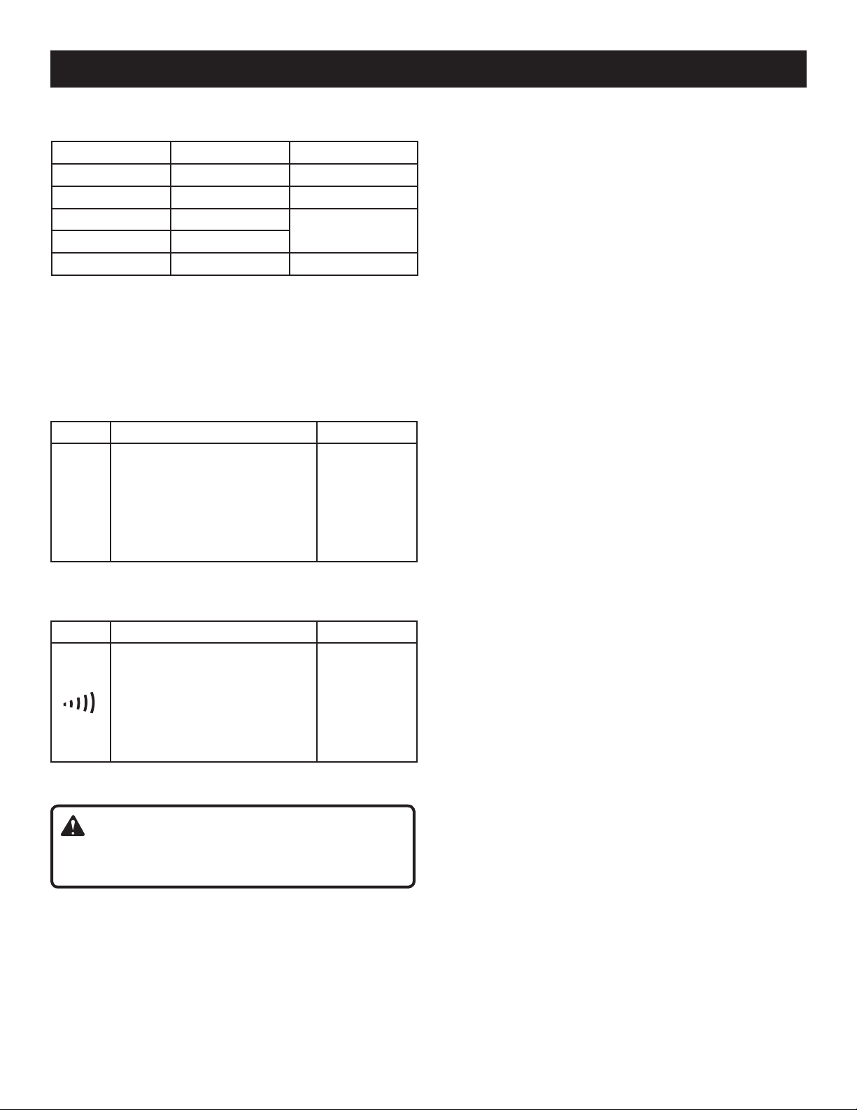
CAPACITANCE
Range Resolution Accuracy
40nF 0.01nF ±(4%+20)
400nF 0.1nF ±(3%+5)
4μF 0.001μF
40μF 0.01μF
100μF 0.1μF ±(8%+5)
Overload Protection: 600V DC/AC rms
NOTE: Accuracy does not include error caused by the
capacitance of test lead and the meter. To reduce the error,
use Relative mode.
For range 100μF, wait about 30 seconds for reading to
settle.
±(4%+5)
DIODE TEST
Range Introduction Remark
The approximate forward voltage drop of the diode will be
2V
Overload Protection: 600V DC/AC rms
displayed.
If the voltage drop is more than
2.0V, the display shows the overrange indicator "OL".
Open Circuit
Voltage:
about 2.4V
Short Circuit
Current:
< 0.6mA
CONTINUITY TEST
Range Introduction Remark
The built-in buzzer will sound if
the resistance is less than about
20Ω.
The buzzer will not sound if the
resistance is more than 150Ω.
Overload Protection: 600V DC/AC rms
Open Circuit
Voltage:
about 0.45V
WARNING:
Do not take readings unless the battery door is securely
closed.
USING RELATIVE MODE
See Figure 4, page 14.
Selecting Relative Mode stores the present reading as a
reference for subsequent measurements and sets the display to zero (0).
To enter Relative Mode, press the REL▵ button. The
symbol "" will appear on the LCD display.
When you perform a new measurement, the display
shows the difference between the first (reference) and
the new measurement.
Press REL▵ again to exit Relative mode and clear the
symbol.
NOTE: For capacitance measurements, the meter
remains in Autorange mode when you select Relative
mode. The actual capacitance to be measured must not
exceed 100μF even if you use Relative mode.
For other measurements which have both Autorange mode
and Manual Range mode, the meter changes to Manual
Range mode when you select Relative mode.
The actual value of the object under test must not exceed the
full-range reading of the selected range when you use Relative
mode. Use a higher measurement range if necessary.
MANUAL RANGING AND AUTORANGING
See Figure 4, page 14.
The meter defaults to Autorange mode in measurement
functions which have both Autorange mode and Manual
range mode. When the meter is in Autorange mode, AUTO
is displayed.
Press the RANGE button to enter the manual range mode.
The AUTO symbol will disappear.
Each press of the RANGE button increases the range.
When the highest range is reached, the meter wraps to
the lowest range.
To exit the manual range mode, press and hold down the
RANGE button for about 2 seconds. The meter will return
to Autorange mode and the symbol AUTO will appear.
NOTE: The RANGE button is disabled in diode, continuity
and capacitance measurement functions.
DATA HOLD MODE
See Figure 4, page 14.
Press the HOLD button to hold the present reading on
the display. The symbol HOLD will appear on the display
as an indicator.
Press the button again to exit Data Hold mode. The sym-
bol HOLD will disappear.
BUILT-IN BUZZER
When you press a button, the built-in buzzer will sound
a beep if the press is effective.
The buzzer will beep several times about 1 minute before
the meter turns off automatically, and give 1 long beep
before the meter turns off automatically.
10 – English
Page 11
OPERATION
ALLIGATOR CLIPS
See Figure 5, page 15.
A set of alligator clips is included with the multimeter, one
for the black lead, and another for the red lead. When you
want the meter to remain connected to a circuit, but want
to keep your hands free for other operations, the alligator
clips will hold the leads in place.
To use the clips:
Make sure the multimeter is turned off.
Insert the end of the red lead probe into the metal connec-
tion inside the alligator clip cover. Make sure it is securely
connected.
Repeat the above step with the black lead and black
alligator clip.
Connect the leads to the circuit using the alligator clips.
NOTE: Do not allow the multimeter to hang by its leads
when the clips are connected to a circuit. Always use the
kick stand or convenience hook, or place the multimeter
on a stable surface.
CAUTION:
To avoid damaging the meter or blowing the fuses, always
remove the test leads from the source or load before
turning the mode selection dial.
MEASURING DC VOLTAGE
See Figure 6, page 15.
NOTE: To avoid electric shock to you or damages to the
meter, do not attempt to measure DC voltage higher than
600V although readings may be obtained.
Connect the black test lead to the COM jack and the red
test lead to the μA/mA jack.
Set the mode selection dial to range.
Select autorange mode or manual range mode with the
RANGE button.
If you use manual range mode and don’t know the magnitude
of the voltage to be measured beforehand, select the highest
range and then reduce it range by range until satisfactory
resolution is obtained.
Connect the test leads across the source or load to be
measured.
Read the display. The polarity of the red lead connection
will be indicated as well.
Remove the test leads from the source or load before
turning the mode selection dial.
MEASURING AC VOLTAGE
See Figure 7, page 15.
NOTE: To avoid electric shock to you or damages to the
meter, do not attempt to measure AC voltage higher than
600V although readings may be obtained.
Connect the black test lead to the COM jack and the red
test lead to the μA/mA jack.
11 – English
Set the mode selection dial to range.
Select autorange mode or manual range mode with the
RANGE button.
If you use manual range mode and don’t know the magnitude
of the voltage to be measured beforehand, select the highest
range and then reduce it range by range until satisfactory
resolution is obtained.
Connect the test leads across the source or load to be
measured.
Read the display.
Remove the test leads from the source or load before
turning the mode selection dial.
MEASURING DC OR AC CURRENT
See Figure 8, page 15.
NOTE: If the magnitude of the current to be measured is not
known beforehand, select the highest range and then reduce
it range by range until satisfactory resolution is obtained.
Connect the black test lead to the COM jack. If the cur-
rent to be measured is less than 400mA, connect the red
test lead to the μA / mA jack. If the current is between
400mA and 10A, connect the red test lead to the 10A
jack instead.
Set the mode selection dial to , or position.
Press the MODE button to select DC or AC current
measurement, the display shows the corresponding
symbol.
Turn off power to the circuit you will measure. Discharge
all high voltage capacitors.
Break the circuit path to be measured, then connect the
test leads in series with the circuit.
Turn on power to the circuit, then read the display. For DC
current measurements, the polarity of the red test lead
connection will be indicated as well.
MEASURING RESISTANCE
See Figure 9, page 15.
NOTE: Before measuring in-circuit resistance, disconnect all
power to the circuit to be tested, and discharge all capacitors fully.
Connect the black test lead to the COM jack and the red
test lead to the μA/mA jack.
NOTE: The polarity of the red lead is positive ( + ).
Set the mode selection dial to Ω range.
Connect the test leads across the load to be measured.
Read the display.
NOTE: For measurements > 1M Ω , the meter may take
a few seconds to stabilize reading. This is normal for high
resistance measurements.
When the input is not connected, i.e. at open circuit, OL
will be displayed as overrange indication.
Page 12

OPERATION
CONTINUITY TEST
See Figure 10, page 15.
NOTE: Before continuity test, disconnect all power to the
circuit to be tested, and discharge all capacitors fully.
Connect the black test lead to the COM jack and the red
test lead to the μA/mA jack.
NOTE: The polarity of the red lead is positive ( + ).
Set the mode selection dial to position.
Connect the test leads across the circuit to be tested.
If the circuit resistance is less than about 20 Ω, the built-
in buzzer will sound.
DIODE TEST
See Figure 11, page 15.
NOTE: Before diode test, disconnect all power to the circuit
to be tested, and discharge all capacitors fully.
Connect the black test lead to the COM jack and the red
test lead to the μA/mA jack.
NOTE: The polarity of the red lead is positive ( + ).
Set the mode selection dial to position.
Connect the red test lead to the anode of the diode to
be tested, and the black test lead to the cathode of the
diode .
Read the approximate forward voltage drop of the diode
on the display.
If the connection is reversed, OL will be shown on the
display.
MEASURING CAPACITANCE
See Figure 12, page 15.
NOTE: Before measurement, make sure that the capacitor
to be measured has been discharged fully.
Connect the black test lead to the COM jack and the red
test lead to the μA/mA jack.
Set the mode selection dial to position.
If the display shows a reading other than zero, press the
REL▵ button.
NOTE: In low capacitance range, if the reading is not
stable, wait a while to let the reading stabilize, and then
press the REL▵ button.
Connect the test leads across the capacitor to be mea-
sured.
Wait until the reading is stable, then take the reading. For
high capacitance measurements, it may take about 30
seconds for reading to be stable.
AUTOMATIC POWER OFF
The display will go blank and the meter will go into Sleep
mode if you do not turn the mode selection dial or press
any button for about 15 minutes. Pressing any button
arouses the meter from Sleep.
To disable the automatic power-off feature, press and hold
down any button while rotating the mode selection dial from
OFF position.
12 – English
Page 13

MAINTENANCE
WARNING:
When servicing, use only identical replacement parts.
Use of any other parts may create a hazard or cause
product damage.
GENERAL MAINTENANCE
Avoid using solvents when cleaning plastic parts. Most
plastics are susceptible to damage from various types of
commercial solvents and may be damaged by their use. Use
clean cloths to remove dirt, dust, oil, grease, etc.
If the multimeter is not operating properly, check the battery
and the fuses. Then recheck the instructions in this manual
to verify correct operating procedures.
WARNING:
Do not at any time let brake fluids, gasoline, petroleumbased products, penetrating oils, etc., come in contact
with plastic parts. Chemicals can damage, weaken or
destroy plastic which may result in serious personal
injury.
CLEANING THE TERMINALS
Dirt or moisture in the terminals can affect readings.
To clean the terminals:
Set the mode selection dial to OFF position and remove
the test leads from the meter.
Remove battery cover and the battery pack. Reinstall the
battery cover.
Shake out any dirt which may exist in the terminals.
Soak a new swab with alcohol.
Work the swab around in each terminal.
To replace the fuses:
Disconnect the test leads.
Remove battery cover and the battery pack. Reinstall the
battery cover.
Remove the 6 Torx screws on the back cover.
NOTE: The screws are not all the same length. The
illustration shows the location of the longer and shorter
screws.
Replace the blown fuse with an identical fuse of the same
rating.
There are two posts on the circuit board and two springs
on the inside back cover of the unit. When replacing the
back cover, make sure the springs fit over the posts.
NOTE: Failure to correctly place the springs over the
posts can result in damage to the unit.
Reinstall the back cover and all the screws.
PRODUCT STORAGE
Before storing, always remove the battery pack from the
product.
BATTERY PACK PREPARATION FOR
RECYCLING
WARNING:
Upon removal, cover the battery pack’s terminals with
heavy-duty adhesive tape. Do not attempt to destroy or
disassemble battery pack or remove any of its components. Lithium-ion batteries must be recycled or disposed
of properly. Also, never touch both terminals with metal
objects and/or body parts as short circuit may result.
Keep away from children. Failure to comply with these
warnings could result in fire and/or serious injury.
REPLACING THE FUSE
See Figure 13, page 15.
To prevent damage or injury, install only replacement fuses
with the specified amperage, voltage, and interrupt ratings.
This meter uses two fuses:
Fuse 1:
F 400mA 690V, Fast, Min. Interrupt Rating 10000A,
ø10 x 38mm
Fuse 2:
F 10A, 600V/690V, Fast, Min. Interrupt Rating 10000A,
ø10 x 38 mm
NOTE: FIGURES (ILLUSTRATIONS) START ON PAGE 14 AFTER FRENCH AND
SPANISH LANGUAGE SECTIONS.
13 – English
Page 14

TABLE DES MATIÈRES
Introduction ..................................................................................................................................................................... 2
Garantie ........................................................................................................................................................................... 2
Règles de sécurité générales ....................................................................................................................................... 3-4
Règles de sécurité particulières ................................................................................................................................... 4-5
Symboles ......................................................................................................................................................................... 6
Caractéristiques .............................................................................................................................................................. 7
Assemblage ..................................................................................................................................................................... 8
Utilisation .................................................................................................................................................................... 8-12
Entretien ........................................................................................................................................................................ 13
Figure numéros (illustrations) ......................................................................................................................................... 14
Commande de pièces / réparation ................................................................................................................. Page arrière
INTRODUCTION
Cet produit offre de nombreuses fonctions destinées à rendre son utilisation plaisante et plus satisfaisante. Lors de la
conception de ce produit, l’accent a été mis sur la sécurité, les performances et la fiabilité, afin d’en faire un outil facile à
utiliser et à entretenir.
GARANTIE
GARANTIE LIMITÉE DE DEUX ANS ET POLITIQUE D’ÉCHANGE DE TRENTE (90) JOURS
POLITIQUE D’ÉCHANGE DE TRENTE (90) JOURS : Pendant les 90 premiers jours suivant la date d’achat, l’utilisateur peut
demander un entretien sous garantie ou échanger le produit en le retournant, accompagné d’une preuve d’achat ainsi que
de tout l’équipement d’origine emballé avec le produit d’origine, au détaillant chez qui l’achat a été effectué. Ce produit de
remplacement sera couvert par cette garantie limitée pendant le reste des deux ans suivant la date d’achat de l’outil original.
GARANTIE LIMITÉE DE DEUX ANS. Ce produit est garanti contre tout vice de fabrication ou de matériel, pour une période
de deux (2) ans à compter de la date d’achat. La garantie couvrant les accessoires de ce produit, à l’exception des piles, est
limitée à 90 jours à compter de la date d’achat de l’accessoire. Pour bénéficier d’un entretien sous garantie, communiquer
avec le service à la clientèle au 1-800-525-2579 pour connaître les instructions de retour sous garantie. Le produit doit être
emballé adéquatement et retourné avec tout l’équipement qui était inclus avec le produit d’origine. Lorsque l’utilisateur
demande un entretien sous garantie, il doit également présenter une preuve d’achat qui comprend la date d’achat (par
exemple, un reçu ou un acte de vente). Les produits défectueux retournés pendant la période de la garantie seront réparés
ou remplacés, à notre discrétion, sans frais, dans un délai de quatre-vingt-dix (90) jours ou moins. L’utilisateur doit assumer
les coûts liés à l’expédition du produit. La présente garantie couvre uniquement les défectuosités survenues lors d’une
utilisation normale. Elle ne couvre pas les défauts de fonctionnement, les pannes ou les défectuosités attribuables à une
mauvaise utilisation, à un usage abusif, à la négligence, à une modification ou à des réparations non autorisées. Cette
garantie s’applique uniquement à l’acheteur d’origine au détail et ne peut être transférée. One World Technologies Inc. ne
donne aucune garantie et ne fait aucune représentation ou promesse relativement à la qualité ou au rendement de ce produit
autres que celles mentionnées spécifiquement dans la présente garantie. Toutes les garanties implicites permises par la loi,
y compris les garanties de valeur marchande ou d’adéquation à un usage particulier, sont limitées à deux ans à compter
de la date d’achat. One World Technologies Inc. n’est pas responsable des dommages directs, indirects ou consécutifs.
Certains états et certaines provinces ne permettent pas d’exonération ou de réserve pour la couverture des dommages
directs ou consécutifs et pour la durée de toute garantie implicite; il se peut donc que l’exonération décrite précédemment
ne puisse s’appliquer. La présente garantie donne au consommateur des droits spécifiques, et il peut bénéficier d’autres
droits qui varient selon les états ou les provinces.
2 - Français
Page 15

RÈGLES DE SÉCURITÉ GÉNÉRALES
AVERTISSEMENT - Lire toutes les instructions.
Le non-respect de toutes les instructions ci-dessous
peut entraîner un choc électrique, un incendie et/ou des
blessures graves. Pour réduire les risques de blessures,
l’utilisateur doit lire le manuel d’utilisation.
CONSERVER CES INSTRUCTIONS
Garder le lieu de travail propre et bien éclairé. Les endroits
encombrés ou sombres sont propices aux accidents.
Éviter tout contact du corps avec des surfaces mises
à la terre, telles que tuyaux, radiateurs, cuisinières et
réfrigérateurs. Le risque de choc électrique est accru
lorsque le corps est mis à la terre.
Ne pas exposer les produits à piles à l’eau ou l’humidité.
La pénétration d’eau dans ces produits à piles accroît le
risque de choc électrique.
Ne pas malmener les fils. Ne jamais utiliser les fils
pour transporter ou tirer le produit à alimentation sur
piles. Garder les fils loin de la chaleur, de l’huile, des
rebords tranchants et des pièces en mouvement. Les fils
endommagés ou entremêlés augmentent le risque de
décharge électrique.
Ne recharger qu’avec l’appareil indiqué.
MODÈLE BLOC DE BATTERIES CHARGEUR
RP4020 AP4001 AP4700, AP4500
Rester attentif, prêter attention au travail et faire preuve
de bon sens lors de l’utilisation de tout produit. Ne pas
utiliser cet produit en état de fatigue ou sous l’influence
de l’alcool, de drogues ou de médicaments. Un moment
d’inattention pendant l’utilisation d’un produit peut entraîner
des blessures graves.
Ne pas travailler hors de portée. Toujours se tenir bien
campé et en équilibre. Ne pas utiliser produit sur une
échelle ou un support instable. Une bonne tenue et un
bon équilibre permettent de mieux contrôler produit en cas
de situation imprévue.
Entretenir cet produits. Vérifier qu’aucune pièce n’est
brisée et s’assurer qu’aucun autre problème ne risque
d’affecter le bon fonctionnement cet produit. En cas de
dommages faire réparer cet produit avant de l’utiliser
de nouveau. Beaucoup d’accidents sont causés par cet
produits mal entretenus.
Porter une tenue appropriée. Ne porter ni vêtements
amples, ni bijoux. Garder les cheveux, les vêtements et
les gants à l’écart des fils ou des pièces en mouvement.
Les vêtements flottants, les bijoux ou les cheveux longs
risquent d’être happés par les pièces en mouvement.
Porter des souliers ou des espadrilles à semelle en
caoutchouc au moment d’utiliser de l’équipement sous
haute tension. S’assurer que les commandes actionnées
empêchent produit de démarrer et que toute l’énergie
dangereuse, y compris l’énergie résiduelle et l’énergie
stockée, est bloquée, déchargée ou libérée avant d’amorcer
le travail.
S’il est nécessaire de sonder ou de toucher de quelque
autre façon des circuits hors tension, les décharger
entre de gros condensateurs de filtrage d’alimentation
(au moins deux fois). Surveiller l’opération de décharge et
s’assurer de l’absence de charge résiduelle en utilisant le
multimètre.
S’il est nécessaire de sonder un circuit sous tension,
appliquer du ruban isolant sur toute la surface des
branches de la sonde d’essai, hormis une section de
1,59 mm (1/16 po) à leur extrémité, pour éviter tout
risque de court-circuit, qui pourrait endommager divers
composants. Fixer l’extrémité de référence du compteur ou
de l’oscilloscope au circuit de retour par la terre approprié
afin de pouvoir sonder à l’aide d’une seule main.
Ne jamais entrer seul dans une zone qui renferme des
sources d’énergie électrique non protégées.
Utiliser uniquement les instruments d’essai et les outils
isolés conçus pour la tension et le courant spécifiés.
Ranger les outils motorisés hors de la portée des
enfants et ne laisser personne n’étant pas familiarisé
avec produit ou ces instructions utiliser produit. Dans
les mains de personnes n’ayant pas reçu des instructions
adéquates, les outils sont dangereux.
Entretenir les outils motorisés. Vérifier qu’aucune pièce
mobile n’est mal alignée ou bloquée, qu’aucune pièce
n’est brisée et s’assurer qu’aucun autre problème ne
risque d’affecter le bon fonctionnement de produit. En
cas de dommages faire réparer produit avant de l’utiliser
de nouveau. Beaucoup d’accidents sont causés par des
outils mal entretenus.
Utiliser produit et accessoires conformément à ces
instrutions pour les applications pour lesquelles ils sont
conçus, en tenant compte des conditions et du type de
travail à exécuter. L’usage d’un outil motorisé pour des
applications pour lesquelles il n’est pas conçu peut être
dangereux.
UTILISATION ET ENTRETIEN DES PRODUITS À
PILES
S’assurer que le commutateur est en position d’arrêt
avant d’insérer le bloc-piles. L’insertion du bloc-piles dans
un outil dont le commutateur est en position de marche peut
causer un accident.
Ne recharger qu’avec l’appareil spécifié par le fabricant.
Un chargeur approprié pour un type de batterie peut créer
un risque d’incendie s’il est utilisé avec un autre type de
batterie.
Utiliser exclusivement le bloc-pile spécifiquement
indiqué pour produit. L’usage de tout autre bloc peut créer
un risque de blessures et d’incendie.
Lorsque le bloc-piles n’est pas en usage, le garder à
l’écart d’articles tels qu’attaches trombones, pièces de
monnaie, clous, vis et autres petits objets métalliques
risquant d’établir le contact entre les deux bornes. La
mise en court-circuit des bornes de batteries peut causer
des étincelles, des brûlures ou un incendie.
En cas d’usage abusif, du liquide peut s’échapper des
batteries. Éviter tout contact avec ce liquide. En cas de
contact accidentel, rincer immédiatement les parties
atteintes avec de l’eau. En cas d’éclaboussure dans les
yeux consulter un médecin. Le liquide s’échappant des
batteries peut causer des irritations ou des brûlures.
Utiliser exclusivement des pièces identiques à celles
d’origine pour les réparations. Se conformer aux
instructions de la section Entretien de ce manuel.
L’usage de pièces non autorisées ou le non-respect des
instructions peut présenter des risques de choc électrique
ou de blessures.
Apprendre à connaître produit. Lire attentivement le
manuel d’utilisation. Apprendre les applications et les
3 - Français
Page 16

RÈGLES DE SÉCURITÉ GÉNÉRALES
limites de produit, ainsi que les risques spécifiques
relatifs à son utilisation. Le respect de cette consigne
réduira les risques d’incendie, de choc électrique et de
blessures graves.
Les
produits
d’être branchés sur une prise secteur, ils sont toujours en
état de fonctionnement. Tenir compte des dangers possibles
lorsque produit n’est pas en usage et lors du remplacement
des batteries. Le respect de cette consigne réduira les risques
d’incendie, de choc électrique et de blessures graves.
Ne pas placer les produits sans fil ou leurs batteries à
proximité de flammes ou d’une source de chaleur. Ceci
réduira les risques d’explosion et de blessures.
Ne pas écraser, faire tomber ou endommager le bloc de
batteries. Ne jamais utiliser un bloc de batteries ou un
fonctionnant sur batteries n’ayant pas besoin
RÈGLES DE SÉCURITÉ PARTICULIÈRES
Avant d’utiliser le multimètre, examiner le boîtier. Porter
une attention particulière à l’isolation entourant les
connecteurs.Examiner les fils d’essai afin de repérer
l’isolation endommagée ou le métal nu. Vérifier la
continuité des fils d’essai. Remplacer tout fil d’essai
endommagé avant d’utiliser le multimètre.
Ne pas utiliser le multimètre s’il fonctionne de façon
anormale. La protection peut être endommagée. En cas
de doute, faire réparer le multimètre.
Ne pas utiliser le multimètre en présence de gaz ou de
poussière inflammables ou explosifs.
Ne pas dépasser la tension indiquée sur le multimètre,
entre les bornes ou entre toute borne et toute prise de
terre.
Au moment de mesurer le courant, couper l’alimentation
du circuit avant de brancher le multimètre dans le circuit.
Il faut se souvenir de placer le multimètre en série avec
le circuit.
Faire preuve de prudence au moment de travailler
au-dessus de 30 V c.a. efficace, d’une crête de 42 V ou de
60 V c.c. Ces tensions présentent un risque de décharge
électrique.
Pendant l’utilisation, garder les doigts derrière les
protecteurs des sondes.
Au moment d’effectuer des connexions, brancher le fil
d’essai commun avant de brancher le fil d’essai sous
tension.
Au moment de débrancher les fils d’essai, débrancher
d’abord le fil d’essai sous tension.
Retirer tous les fils d’essai du multimètre avant d’ouvrir
le couvercle du compartiment des piles ou une section
du boîtier.
Ne pas utiliser le multimètre si la porte du compartiment
des piles ou des sections du boîtier sont desserrées ou
retirées. La porte du compartiment des piles doit être
bien fermée avant d’utiliser le multimètre.
4 - Français
chargeur qui est tombé, a été écrasé, a reçu un choc
violent ou a été endommagé de quelque façon que ce
soit. Une batterie endommagée risque d’exploser. Éliminer
immédiatement toute batterie endommagée, selon une
méthode appropriée.
Les batteries peuvent exploser en présence d’une source
d’allumage, telle qu’une veilleuse. Pour réduire les risques
de blessures graves, ne jamais utiliser un appareil sans fil,
quel qu’il soit, en présence d’une flamme vive. En explosant,
une batterie peut projeter des débris et des produits
chimiques. En cas d’exposition, rincer immédiatement les
parties atteintes avec de l’eau.
Pour un résultat optimal, le batteries de
être rechargées dans un local où la température est de
10 à 35 °C (50 à 94°F). Ne pas ranger produit à l’extérieur
ou dans un véhicule.
produits
doivent
Pour éviter les lectures erronées, qui peuvent entraîner
des décharges électriques ou des blessures, remplacer
ou charger la pile dès que l’indicateur de faible intensité
de pile (
) apparaît.
Utiliser uniquement le multimètre tel que spécifié dans
le présent manuel. Sinon, les fonctions de sécurité de
l’instrument risquent d’être endommagées.
Lorsque produit fonctionne en mode « Relative » (Relatif)
ou « Data Hold » (Retenue de données), agir prudemment,
car la tension peut être dangereusement élevée.
S’isoler du sol. Être extrêmement prudent afin d’éviter
une électrocution.
Ne pas utiliser le multimètre avec les mains mouillées ou
si l’appareil est mouillé.
Respecter les codes de sécurité locaux et nationaux.
Au moment de travailler dans un endroit renfermant des
conducteurs dangereux sous tension et non protégés,
porter de l’équipement de protection individuel pour
éviter toute blessure découlant d’une décharge ou de
l’explosion d’un arc électrique.
Danger toujours présent : Lorsqu’une borne d’entrée
est branchée à un potentiel sous tension dangereux, il
importe de noter que ce potentiel peut circuler par toutes
les autres bornes!
CATIII – La catégorie de mesure III convient aux mesures
effectuées lors d’une installation dans un bâtiment.
Par exemple, les mesures prises sur les tableaux de
distribution, les disjoncteurs, le câblage (ce qui inclut
les câbles, les barres omnibus, les boîtes de jonction,
les interrupteurs ainsi que les prises de courant des
installations fixes), ainsi que l’équipement utilisé à des
fins industrielles et quelques autres appareils comme les
moteurs stationnaires raccordés de façon permanente à
des installations fixes. Ne pas utiliser le multimètre pour
prendre des mesures qui se situent dans la catégorie de
mesure IV.
Page 17

DECLARATION OF CONFORMITY
We declare under our sole responsibility that this product is in conformity with the following standards or
standardized documents.
2006/95/EC
EN61010-1:2001
EN61010-031:2002
DECLARATION OF CONFORMITY
We declare under our sole responsibility that this product is in
conformity with the following standards or standardized documents.
2006/95/EC
EN61010-1:2001
EN61010-031:2002
DECLARATION OF CONFORMITY
We declare under our sole responsibility that this product is in
conformity with the following standards or standardized documents.
2006/95/EC
EN61010-1:2001
EN61010-031:2002
DECLARATION OF CONFORMITY
We declare under our sole responsibility that this product is in
conformity with the following standards or standardized documents.
2006/95/EC
EN61010-1:2001
EN61010-031:2002
RÈGLES DE SÉCURITÉ PARTICULIÈRES
Utiliser les bornes, les fonctions et les plages qui
conviennent aux mesures.
Avant de mesurer le courant, vérifier les fusibles du
multimètre et couper l’alimentation du circuit avant d’y
brancher le multimètre.
Avant de tourner le commutateur de plage pour changer
de fonction, débrancher les fils d’essai du circuit mis à
l’essai.
S’assurer que les fils d’essai et le commutateur sont
placés à la position appropriée pour obtenir la mesure
désirée.
Ne jamais mesurer la résistance d’un circuit sous tension.
Ne jamais toucher une source de tension avec les sondes
si les fils d’essai sont branchés dans une entrée de 10 A
ou de 400 mA.
Avant d’utiliser le multimètre, vérifier son fonctionnement
en mesurant une tension connue.
Éviter de travailler seul.
Pour éviter d’endommager le multimètre ou
l’équipement mis à l’essai, respecter les directives
suivantes :
• Couper l’alimentation du circuit et décharger tous les
condensateurs haute tension avant de mettre à l’essai
la résistance, la continuité ou les diodes.
• Avant de mesurer le courant, vérifier les fusibles du
multimètre et couper l’alimentation du circuit avant
d’y brancher le multimètre.
Conserver ces instructions. Les consulter fréquemment
et les utiliser pour instruire d’autres utilisateurs. Si
cet produit est prêté, il doit être accompagné de ces
instructions.
PROPOSITION 65 DE LA CALIFORNIE
AVERTISSEMENT :
Ce produit peut contenir des produits chimiques,
notamment du plomb, identifiés par l’état de Californie
comme causes de cancer, de malformations congénitales
et d’autres troubles de l’appareil reproducteur. Bien se
laver les mains après toute manipulation.
DÉCLARATION DE CONFORMITÉ
Nous déclarons, en assumant la responsabilité, que ce produit est conforme aux normes suivantes ou aux
documents normalisés.
2006/95/EC
EN61010-1:2001
EN61010-031:2002
Machine: 4V Digital Multimeter Type: RP4020
Multimètre numérique
Multimètre numérique
Nom de l’entreprise :
Name of company: TECHTRONIC INDUSTRIES CO. LTD.
Adresse :
Address: 24/F, CDW BUILDING
388 CASTLE PEAK ROAD
TSUEN WAN
HONG KONG
Web: www.ttigroup.com
Nom/titre :
Name/Title: Brian Ellis
Vice President - Engineering
Signature :
Signature:
Marques de commerce :
La marque Ryobi est utilisée sur le fondement d’une licence accordée par Ryobi Limited.
5 - Français
Page 18

SYMBOLES
Les termes de mise en garde suivants et leur signification ont pour but d’expliquer le degré de risques associé à
l’utilisation de ce produit.
SYMBOLE SIGNAL SIGNIFICATION
DANGER:
AVERTISSEMENT :
ATTENTION :
ATTENTION :
Certains des symboles ci-dessous peuvent être utilisés sur produit. Veiller à les étudier et à apprendre leur signification.
Une interprétation correcte de ces symboles permettra d’utiliser produit plus efficacement et de réduire les risques.
Indique une situation extrêmement dangereuse qui, si elle n’est pas évitée,
aura pour conséquences des blessures graves ou mortelles.
Indique une situation potentiellement dangereuse qui, si elle n’est pas évitée,
pourrait entraîner des blessures graves ou mortelles.
Indique une situation potentiellement dangereuse qui, si elle n’est pas évitée,
pourraît entraîner des blessures légères ou de gravité modérée.
(Sans symbole d’alerte de sécurité) Indique une situation pouvant entraîner
des dommages matériels.
SYMBOLE NOM DÉSIGNATION / EXPLICATION
Symbole d’alerte
de sécurité
Lire le manuel
d’utilisation
Avertissement concernant l’humidité
Indique un risque de blessure potentiel.
Pour réduire les risques de blessures, l’utilisateur doit lire et veiller à bien comprendre
le manuel d’utilisation avant d’utiliser ce produit.
Ne pas exposer à la pluie ou l’humidité.
Symbole d’alerte
de sécurité
DC V Tension
AC V Tension
Ohms L'unité de la résistance électrique
Continuité Chemin d'accès complet pour les flux de courant
Capacité Capacité d'un élément pour stocker une charge électrique
Diode
A Ampères Intensité
Hz Hertz Fréquence (cycles par seconde)
min
.../min
Minutes Temps
Courant continu Type ou caractéristique du courant
Courant alternatif Type de courant
Par minute Tours, coups, vitesse périphérique, orbites, etc., par minute
Ce produit utilise le piles de lithium-ion (Li-ion). Les réglementations locales ou
gouvernementales peuvent interdire de jeter les piles dans les ordures ménagères.
Consulter les autorités locales compétentes pour les options de recyclage et/ou
l’élimination.
Un tube électronique de deux électrodes contenant une anode et une
cathode.
6 - Français
Page 19

FICHE TECHNIQUE
CARACTÉRISTIQUES
Tension des batteries ......................................................4V
Écran ........... Écran ACL numérique de 95,25 mm (3 ¾ po)
Lecture maximale sur l’écran ACL ..............................3999
Catégorie de mesure ................................................ CAT III
Tension maximum ......................................................600 V
Courant maximal ......................................................... 10 A
Fréquence d’échantillonnage ................ 2 à 3 fois/seconde
*Taux d’étanchéité : Précise la protection environnementale dont profite le boîtier. Un taux d’étanchéité de 54 rend compte d’une protection
contre les dépôts dangereux de poussière et d’une protection contre toute pulvérisation d’eau (dans toutes les directions). Le taux de
résistance à l’eau spécifié s’applique uniquement si le couvercle du compartiment des piles est installé.
VEILLER À BIEN CONNAÎTRE LA
MULTIMÈTRE
Voir la figures 1 - 3, page 14.
La sécurité d’utilisation de ce produit exige la compréhension
des informations apposées sur produit et contenues dans ce
manuel d’utilisation. Avant d’utiliser ce produit, se familiariser
avec toutes ses fonctions et règles de sécurité.
Le présent multimètre numérique a été conçu conformément
à la norme 61010 de la Commission électrotechnique
internationale (CEI) concernant les instruments électroniques
de mesure appartenant à la catégorie de mesure III (CAT III,
600 V) et présentant un niveau de pollution 2.
ÉCRAN ACL NUMÉRIQUE
L’afficheur ACL comprend des chiffres faciles à lire pour
exécuter diverses fonctions.
CADRAN DE SÉLECTION DU MODE
Permet de choisir la fonction désirée ainsi que d’allumer ou
d’éteindre le multimètre.
RANGEMENT, BÉQUILLE DE SUPPORT ET
CROCHET PRATIQUE INTÉGRÉS
Pour empêcher la sonde de s’empêtrer, pour la soutenir
facilement et la suspendre pratiquement n’importe où à
l’aide d’une seule main.
Taux d’étanchéité .......................................................... 54*
Température de service ....................0°C ~ 35°C, <75%RH
Coefficient de température ..................................................
0.2 x (niveau de précision spécifié) / °C (<18°C or 28°C)
Température d’entreposage ......... -10°C ~ 60°C, <85%RH
Altitude d’exploitation ............................. 0 to 2000 meters
BOUTON « RANGE » (PLAGE)
Permet de passer du mode de plage automatique au mode
de plage manuel, en plus de sélectionner la plage manuelle
désirée.
CONNECTEUR FEMELLE DE 10 A
Prise du fil d’essai rouge pour les valeurs de courant situées
entre 400 mA et 10 A.
CONNECTEUR FEMELLE COMMUN
Prise du fil d’essai noir pour toutes les mesures.
ΜA/MA CONNECTEUR FEMELLE
Prise du fil d’essai rouge pour toutes les mesures, à l’exception
des valeurs de courant de 400 mA et plus.
BOUTON « BACKLIGHT »
(RÉTROÉCLAIRAGE)
Permet d’allumer et d’éteindre le rétroéclairage.
BOUTON « REL▵ » (RELATIF)
Permet de passer en mode « Relative ».
BOUTON « HOLD » (RETENUE)
Permet de passer en mode « Data Hold » (Retenue des
données).
RANGEMENT DU COUVERCLE DE LA SONDE
FONCTION D’ARRÊT AUTOMATIQUE
Nécessite moins de temps d’arrêt pour la charge de produit,
ce qui permet d’augmenter la productivité.
Lorsque les fils noir et rouge sont utilisés, le couvercle de la
sonde peut être placé dans le compartiment de rangement
situé à l’arrière de l’unité.
BOUTON « MODE »
Permet de passer de la mesure du courant c.c. à celle du
courant c.a.
7 - Français
PINCES CROCODILE
L’ensemble comprend deux pinces crocodile isolées
afin de permettre à l’utilisateur de fixer les sondes sur
un circuit lorsqu’il doit se libérer les mains.
Page 20

ASSEMBLAGE
DÉBALLAGE
Ce produit a été expédié complètement assemblé.
Avec précaution, sortir l’produit et les accessoires de la
boîte. S’assurer que toutes les pièces figurant sur la liste
de contrôle sont incluses.
AVERTISSEMENT :
Ne pas utiliser le produit s’il n’est pas complètement
assemblé ou si des pièces semblent manquantes ou
endommagées. Le fait d’utiliser un produit assemblé
de façon inadéquate ou incomplète peut entraîner des
blessures graves.
Examiner soigneusement l’produit pour s’assurer que rien
n’a été brisé ou endommagé en cours de transport.
Ne pas jeter les matériaux d’emballage avant d’avoir
soigneusement examiné l’produit et avoir vérifié qu’il
fonctionne correctement.
UTILISATION
Si des pièces sont manquantes ou endommagées,
appeler le 1-800-525-2579.
LISTE DE CONTRÔLE D’EXPÉDITION
Multimètre
Sondes
Pinces crocodile
Manuel d'utilisation
AVERTISSEMENT:
Si des pièces manquent ou sont endommagées, ne pas
utiliser cet produit avant qu’elles aient été installées.
Ne pas prendre cette précaution pourrait entraîner des
blessures graves.
AVERTISSEMENT:
Ne pas laisser la familiarité avec produits faire oublier la
prudence. Ne pas oublier qu’une fraction de seconde
d’inattention peut entraîner des blessures graves.
AVERTISSEMENT:
Respecter les règles de sécurité générales et spécifiques
décrites dans le présent manuel au moment de prendre
des mesures électriques et de travailler en présence
de tensions élevées. Ne pas respecter les mesures de
sécurité standards peut entraîner une électrocution et
des blessures graves.
RETRAIT / INSTALLATION DUE BLOC-PILES
Voir la figure 2, page 14.
S’assurer que le cadran de sélection du mode est réglé
à la position « Off » (Arrêt) avant d’installer ou de retirer
le bloc-piles.
Pour retirer le couvercle du compartiment des piles :
Utiliser un petit tournevis à pointe cruciforme pour
desserrer les vis et retirer le couvercle du compartiment
des piles.
NOTE : Les vis doivent demeurer fixées sur le couvercle.
Un joint torique occupe la rainure du logement. S’assurer
que le joint torique est complètement appuyé dans la
rainure.
Insérer le bloc-piles dans la direction indiquée.
Replacer le couvercle du compartiment des piles et le
fixer à l’aide des vis.
8 - Français
Ne pas tenter de prendre une lecture si la porte du
compartiment des piles n’est pas bien fermée.
AVERTISSEMENT :
Toujours retirer la pile de l’outil au moment d’assembler
des pièces, d’effectuer des réglages et de procéder au
nettoyage, ou lorsque l’outil n’est pas utilisé. Le fait de
retirer la pile permet d’empêcher un démarrage accidentel
pouvant entraîner des blessures graves.
LECTURE DE L’ÉCRAN ACL
Voir la figure 3, page 14.
SYMBOLE SIGNIFICATION
AUTO
HOLD
Le mode de plage automatique est
sélectionné
Le mode « Data Hold » (Retenue des
données) est activé
Le mode « Relative » est activé
L’essai de continuité est sélectionné
L’essai de la diode est sélectionné
DC
Symbole négatif
AC
La pile est faible et doit être rechargée ou
remplacée immédiatement
Page 21

UTILISATION
UNITÉS SUR L’ÉCRAN ACL
Unité de tension
mV, V
μA, mA,
A
Ω, k Ω,
MΩ
nF,
μF
mV : millivolt; V : volt;
1V=103mV
Unité de courant
µA : microampère; mA : milliampère; A : ampère;
1A=103mA=106µA
Unité de résistance
Ω : ohm; kΩ : kilohm; MΩ : mégohm;
1M Ω =103k Ω =106 Ω
Unité de capacité
nF : nanofarad; µF : microfarad;
1F=106µF=109nF=1012pF
PRÉCISION
La précision est garantie pour une période d’un an suivant
l’étalonnage, à une température située entre 18 ºC et 28 ºC
(64,4 ºF et 82,4 ºF) et à une humidité relative inférieure à
75 %. Excepté pour les plages spécialement spécifiées, le
degré de précision varie de 8 % à 100 %.
Les spécifications sur la précision prennent la forme
suivante :
± ([% de la lecture] + [nombre de chiffres les moins
significatifs])
TENSION C.C.
Plage Resolution Précision
400mV 0.1mV ±(1.0%+5)
4V 0.001V
±(0.8%+3)40V 0.01V
400V 0.1V
600V 1V ±(1.0%+3)
Impédance d’entrée : Plage de 400 mV : > 1 000 MΩ
Les autres plages : 10 MΩ
NOTE : La plage de 600 V comporte un degré de
précision de 20 % à 100%.
TENSION C.A.
Plage Resolution Précision
4V 0.001V
±(1.0%+5)40V 0.01V
400V 0.1V
600V 1V ±(1.2%+5)
Impédance d’entrée : 10MΩ
Plage de fréquence : 40Hz 400 Hz
Réponse : Moyenne, étalonnée en valeur efficace de
l’onde sinusoïdale.
NOTE : La plage de 600 V comporte un degré de
précision de 20 % à 100%.
.
9 - Français
COURANT C.C.
Plage Resolution Précision
400µA 0.1µA ±(1.2%+3)
4000µA 1µA ±(1.0%+3)
40mA 0.01mA ±(1.5%+3)
400mA 0.1mA ±(1.0%+3)
4A 0.001A ±(1.8%+3)
10A 0.01A ±(2.0%+5)
Protection contre les surcharges :
Fusible 1 : F 400mA, 690V
Fusible 2 : F 10A, 600V / 690V
Courant maximal à l’entrée : 10 A (pour les entrées > 2 A :
durée de la mesure < 10 sec, intervalle > 15 minutes)
Chute de tension maximale au moment de la mesure :
200 mV (à l’exception de la plage de 10 A)
NOTE : La plage de 10A comporte un degré de précision
de 20 % à 100%.
COURANT C.A.
Plage Resolution Précision
400µA 0.1µA
4000µA 1µA
40mA 0.01mA
400mA 0.1mA
4A 0.001A ±(2.0%+5)
10A 0.01A ±(2.5%+10)
Protection contre les surcharges :
Fusible 1 : F 400mA, 690V
Fusible 2 : F 10A, 600V / 690V
Courant maximal à l’entrée :
durée de la mesure < 10 sec, intervalle > 15 minutes)
Plage de fréquence : 40Hz 400 Hz
Réponse : Moyenne, étalonnée en valeur efficace de
l’onde sinusoïdale
Chute de tension maximale au moment de la mesure :
200 mV (à l’exception de la plage de 10 A)
NOTE : La plage de 10A comporte un degré de précision
de 20 % à 100%.
10 A (pour les entrées > 2 A :
±(1.5%+5)
±(1.8%+5)
RÉSISTANCE
Plage Resolution Précision
400Ω 0.1Ω ±(1.0%+5)
4kΩ 0.001kΩ
40kΩ 0.01kΩ
400kΩ 0.1kΩ
4MΩ 0.001MΩ
40MΩ 0.01MΩ ±(1.8%+5)
Protection contre les surcharges : 600V DC/AC rms
±(1.0%+3)
Page 22

UTILISATION
CAPACITÉ
Plage Resolution Précision
40nF 0.01nF ±(4%+20)
400nF 0.1nF ±(3%+5)
4µF 0.001µF
40µF 0.01µF
100µF 0.1µF ±(8%+5)
Protection contre les surcharges : 600V DC/AC rms
NOTE : La précision ne tient pas compte des erreurs causées
par la capacité des fils d’essai et du multimètre. Pour réduire
l'erreur, employez le mode relatif.
Dans le cas de la plage de 100 µF, attendre environ 30
secondes pour obtenir une lecture stable.
±(4%+5)
ESSAI DE LA DIODE
Plage Introduction Remarque
La chute de tension directe de
la diode s’affiche.
2V
Protection contre les surcharges : 600V: DC/AC rms
Si la chute de tension est
supérieure à 1,0 V, l’indicateur
de dépassement « OL » apparaît
à l’écran.
Tension à
circuit ouvert :
environ 1,5 V
Courant en
court-circuit :
< 0,6 mA
ESSAI DE CONTINUITÉ
Plage Introduction Remarque
L’avertisseur intégré retentit si
la résistance est inférieure à
50 Ω.
L’avertisseur ne retentit pas si
la résistance est supérieure à
150 Ω.
Protection contre les surcharges : 600V: DC/AC rms
Tension à
circuit ouvert :
environ
0,45 V
Au moment de prendre une nouvelle mesure, l’écran
affiche la différence entre la première mesure (mesure de
référence) et la nouvelle.
Appuyer de nouveau sur le bouton « REL▵ » pour quitter
le mode « Relative » et effacer le symbole.
NOTE : Pour mesurer la capacité, le multimètre doit
demeurer en mode de plage automatique lorsque le mode
« Relative » est sélectionné. La capacité réelle qui doit
être mesurée ne doit pas excéder 100 µF, et ce, même
si l’instrument est en mode « Relative ».
Pour toutes les autres mesures effectuées en modes de
plage automatique et manuel, le multimètre passe en mode
de plage manuel lorsque l’utilisateur sélectionne le mode «
Relative ».
En mode « Relative », la valeur réelle de l’objet mis à l’essai
ne doit pas dépasser la lecture maximale possible de la plage
sélectionnée. Utiliser une plage de mesure plus grande, au
besoin.
MODES DE PLAGE MANUEL ET
AUTOMATIQUE
Voir la figure 4, page 14.
Le multimètre se règle par défaut en mode de plage
automatique pour les fonctions de mesure compatibles
avec les modes de plage automatique et manuel. Lorsque
le multimètre est en mode de plage automatique, le symbole
« AUTO » est affiché.
Appuyer sur le bouton « RANGE » (Plage) pour passer en
mode de plage manuel. Le symbole « AUTO » disparaît.
Chaque pression sur le bouton « RANGE » (Plage) permet
d’augmenter la plage. Lorsque la plage la plus élevée
est atteinte, le multimètre retourne à la plage la moins
élevée.
Pour quitter le mode de plage manuel, appuyer sur le
bouton « RANGE » (Plage) et le tenir enfoncé pendant
environ deux secondes. Le multimètre retourne en mode
de plage automatique et le symbole « AUTO » apparaît.
NOTE : Le bouton « RANGE » (Plage) est désactivé
lorsque les fonctions de mesure de la diode, de la
continuité et de la capacité sont utilisées.
AVERTISSEMENT:
Ne prendre aucune mesure si la porte du compartiment
des piles n’est pas bien fermée.
UTILISATION DU MODE « RELATIVE »
Voir la figure 4, page 14.
Le fait de sélectionner le mode « Relative » permet d’enregistrer
la lecture actuelle aux fins de référence pour les mesures
éventuelles et de réinitialiser l’écran à zéro (0).
Pour passer au mode « Relative », appuyer sur le bouton «
REL▵ ». Le symbole «▵ » apparaît sur l’afficheur ACL.
10 - Français
MODE « DATA HOLD » (RETENUE DE DONNÉES)
Voir la figure 4, page 14.
Appuyer sur le bouton « HOLD » (Retenue) pour conserver
la lecture actuelle sur l’écran. Le symbole « HOLD »
s’affiche sur l’écran à titre d’indicateur.
Appuyer de nouveau sur le bouton pour quitter le mode de
retenue des données. Le symbole « HOLD » disparaît.
AVERTISSEUR INTÉGRÉ
Lorsque l’utilisateur appuie sur un bouton, l’avertisseur
intégré retentit si l’opération a réussi.
Environ une minute avant que le multimètre ne s’éteigne
automatiquement l’avertisseur retentira brièvement
un signal sonore retentit à plusieurs reprises et il
retentira longuement une fois juste avant l’extinction de
l’instrument.
Page 23

UTILISATION
PINCES CROCODILE
Voir la figure 5, page 15.
Le multimètre comprend un ensemble de pinces crocodile,
soit une pince pour le fil noir et une autre pour le fil rouge.
Si l’utilisateur désire que le multimètre demeure raccordé à
un circuit, mais désire également se libérer les mains pour
effectuer d’autres opérations, il peut employer les pinces
crocodile pour fixer les fils en place.
Pour utiliser les pinces :
S’assurer que le multimètre est éteint.
Insérer l’extrémité de la sonde du fil rouge dans le raccord
en métal situé à l’intérieur du couvercle de la pince
crocodile. S’assurer qu’elle est fixée solidement.
Répéter les étapes précédentes avec le fil noir et la pince
crocodile noire.
Raccorder les fils au circuit à l’aide des pinces
crocodile.
NOTE : Ne pas suspendre le multimètre par ses fils si
les pinces sont raccordées au circuit. Toujours utiliser la
béquille de support ou le crochet pratique, ou placer le
multimètre sur une surface stable.
ATTENTION :
Pour éviter d’endommager le multimètre ou de faire
sauter les fusibles, toujours retirer les fils d’essai de la
source ou de la charge avant de tourner le cadran de
sélection du mode.
MESURE DE LA TENSION C.C.
Voir la figure 6, page 15.
NOTE : Pour éviter une électrocution ou des dommages
au multimètre, ne pas tenter de mesurer une tension c.c.
supérieure à 600 V, et ce, même s’il est possible de prendre
les lectures.
Brancher le fil d’essai noir dans le connecteur femelle
COM et le fil d’essai rouge dans le connecteur femelle
μA/mA.
Régler le commutateur de plage à la plage .
Sélectionner le mode de plage automatique ou le mode
de plage manuel à l’aide du bouton « RANGE » (Plage).
Si vous utilisez le recours au mode de plage manuel mais
vous ignorez l’ampleur de la tension qui doit être mesurée,
sélectionner la plage la plus élevée et la réduire graduellement
jusqu’à ce qu’une résolution appropriée soit obtenue.
Brancher les fils d’essai aux bornes de la source ou de
la charge à mesurer.
Lire l’écran. La polarité de la connexion du fil rouge sera
également indiquée.
Retirer les fils d’essai de la source ou de la charge avant
de tourner le cadran de sélection du mode.
MESURE DE LA TENSION C.A.
Voir la figure 7, page 15.
NOTE : Pour éviter une électrocution ou des dommages
au multimètre, ne pas tenter de mesurer une tension c.a.
supérieure à 600 V, et ce, même s’il est possible de prendre
les lectures.
Brancher le fil d’essai noir dans le connecteur femelle
COM et le fil d’essai rouge dans le connecteur femelle
μA/mA.
Régler le commutateur de plage à la plage .
Sélectionner le mode de plage automatique ou le mode
de plage manuel à l’aide du bouton « RANGE » (Plage).
Si vous utilisez le recours au mode de plage manuel mais
vous ignorez l’ampleur de la tension qui doit être mesurée,
sélectionner la plage la plus élevée et la réduire graduellement
jusqu’à ce qu’une résolution appropriée soit obtenue.
Brancher les fils d’essai aux bornes de la source ou de
la charge à mesurer.
Lire l’écran. La polarité de la connexion du fil rouge sera
également indiquée.
Retirer les fils d’essai de la source ou de la charge avant
de tourner le cadran de sélection du mode.
MESURE DU COURANT C.C. OU C.A.
Voir la figure 8, page 15.
NOTE : Si l’ampleur du courant à mesurer n’est pas connue
à l’avance, sélectionner la plage la plus élevée et la réduire
graduellement jusqu’à ce qu’une résolution appropriée soit
obtenue.
Brancher le fil d’essai noir dans le connecteur femelle
COM. Si le courant à mesurer est inférieur à 400 mA,
brancher le fil d’essai rouge dans le connecteur femelle
μA / mA. Si le courant se situe entre 400 mA et 10 A,
brancher plutôt le fil d’essai rouge dans le connecteur
femelle 10 A.
Régler le commutateur de plage à la position ,
ou .
Appuyer sur le bouton « MODE » pour sélectionner la
mesure de courant c.c. ou c.a.; le symbole correspondant
apparaît à l’écran.
Couper l’alimentation du circuit sur lequel la mesure doit
être prise. Décharger tous les condensateurs à haute
tension.
Briser le parcours du circuit qui doit être mesuré, puis
raccorder les fils d’essai en série avec le circuit.
Rétablir l’alimentation du circuit, puis lire l’écran. Dans
le cas des mesures de courant c.c., la polarité de la
connection du fil d’essai rouge est également indiquée.
MESURE DE LA RÉSISTANCE
Voir la figure 9, page 15.
Brancher le fil d’essai noir dans le connecteur femelle
COM et le fil d’essai rouge dans le connecteur femelle
μA/mA. (Note : La polarité du fil rouge est
positive [+].)
Régler le commutateur de plage à Ω.
Raccorder les fils d’essai aux bornes de la charge à
mesurer.
11 - Français
Page 24

UTILISATION
Lire l’écran.
NOTE : Dans le cas des mesures supérieures à 1 MΩ, il faut
quelques secondes au multimètre pour stabiliser la lecture. Il
s’agit d’une situation normale pour les mesures appliquées
à une résistance élevée.
Lorsque l’entrée n’est pas connectée, c’est-à-dire qu’il
s’agit d’un circuit ouvert, le symbole « OL » s’affiche
comme indication de dépassement.
ESSAI DE CONTINUITÉ
Voir la figure 10, page 15.
NOTE : Avant de procéder à l’essai de continuité,
couper l’alimentation du circuit mis à l’essai et décharger
complètement tous les condensateurs.
Brancher le fil d’essai noir dans le connecteur femelle
COM et le fil d’essai rouge dans le connecteur femelle
μA/mA.
NOTE : La polarité du fil de couleur rouge est positive
(+).
Régler le commutateur de plage à la position .
Raccorder les fils d’essai sur les bornes du circuit mis à
l’essai.
Si la résistance du circuit est inférieure à environ 50 Ω,
l’avertisseur intégré retentit.
ESSAI DE LA DIODE
Voir la figure 11, page 15.
NOTE : Avant de procéder à l’essai de la diode, couper
l’alimentation du circuit mis à l’essai et décharger
complètement tous les condensateurs.
Brancher le fil d’essai noir dans le connecteur femelle
COM et le fil d’essai rouge dans le connecteur femelle
μA/mA.
NOTE : La polarité du fil rouge est positive (+).
MESURE DE LA CAPACITÉ
Voir la figure 12, page 15.
NOTE : Avant de procéder à la mesure, s’assurer que
le condensateur qui doit être mesuré a été déchargé
complètement.
Brancher le fil d’essai noir dans le connecteur femelle
COM et le fil d’essai rouge dans le connecteur femelle
μA/mA.
Régler le commutateur de plage à la position .
Si l’écran affiche une lecture autre que zéro, appuyer sur
le bouton « REL▵ ».
NOTE : Dans le cas d’une plage de faible capacité, si la
lecture n’est pas stable, attendre un moment qu’elle se
stabilise, puis appuyer sur le bouton « REL▵ ».
Raccorder les fils d’essai aux bornes du condensateur à
mesurer.
Attendre que la lecture soit stable, puis prendre la lecture.
Dans le cas des mesures appliquées à une capacité
élevée, la lecture peut prendre environ 30 secondes pour
se stabiliser.
COUPER L'ALIMENTATION ÉLECTRIQUE
AUTOMATIQUE
L'affichage ira blanc et le mètre entrera dans le mode de
sommeil si vous ne tournez pas le cadran de choix de
mode ou n'appuyez sur aucun bouton pendant environ
15 minutes. Appuyer sur n'importe quel bouton réveille
le mètre du sommeil.
Pour désactiver la configuration automatique de puissanceau loin, appuyez sur et maintenez n'importe quel bouton tout
en tournant le cadran tout en tournant le cadran sélecteur
de mode à partir de la position « OFF » (Arrêt).
Régler le commutateur de plage à la position .
Raccorder le fil d’essai rouge à l’anode de la diode mise
à l’essai et le fil d’essai noir à la cathode de la diode.
Lire la chute de tension directe approximative de la diode
à l’écran.
Si la connexion est inversée, le symbole « OL » s’affiche
à l’écran.
12 - Français
Page 25

ENTRETIEN
AVERTISSEMENT:
Utiliser exclusivement des pièces d’origine pour les
réparations. L’usage de toute autre pièce pourrait créer
une situation dangereuse ou endommager l’produit.
ENTRETIEN GÉNÉRAL
Éviter d’utiliser des solvants pour le nettoyage des pièces en
plastique. La plupart des matières plastiques peuvent être
endommagées par divers types de solvants du commerce.
Utiliser un chiffon propre pour éliminer la saleté, la poussière,
l’huile, la graisse, etc.
Si le multimètre ne fonctionne pas correctement, vérifier la
pile et les fusibles. Puis, vérifier de nouveau les instructions
du présent manuel pour s’assurer des procédures d’utilisation
appropriées.
AVERTISSEMENT:
Do not at any time let brake fluids, gasoline, petroleumbased products, penetrating oils, etc., come in contact
with plastic parts. Chemicals can damage, weaken or
destroy plastic which may result in serious personal
injury.
Pour remplacer les fusibles :
Débrancher les fils d’essai.
Retirer le couvercle du compartiment des piles et le
bloc-piles. Réinstaller le couvercle du compartiment des
piles.
Retirer les six vis à empreinte hexalobée du couvercle
arrière.
NOTE : Les vis ne sont pas toutes de la même longueur.
L’image montre l’emplacement des vis longues et
courtes.
Remplacer le fusible sauté par un fusible identique de
même calibre.
On retrouve deux montants sur la carte de circuit imprimé
et deux ressorts à l’intérieur du couvercle arrière de l’unité.
Au moment de replacer le couvercle arrière, s’assurer que
les ressorts s’ajustent au-dessus des montants.
NOTE : Ne pas placer correctement les ressorts
au-dessus des montants peut endommager l’unité.
Réinstaller le couvercle arrière ainsi que toutes les vis.
ENTREPOSAGE DE PRODUIT
Avant l’entreposage, toujours retirer le bloc-piles le
produit.
NETTOYAGE DES BORNES
La saleté ou la moisissure présente sur les bornes peut avoir
un effet sur les lectures.
Pour nettoyer les bornes :
Régler le commutateur de plage à la position « OFF »
(Arrêt), puis retirer les fils d’essai du multimètre.
Retirer le couvercle du compartiment des piles et le
bloc-piles. Réinstaller le couvercle du compartiment des
piles.
Secouer la poussière des bornes.
Imbiber un coton-tige propre avec de l’alcool.
Passer le coton-tige autour de chaque borne.
REMPLACEMENT DU FUSIBLE
Voir la figure 13, page 15.
Pour éviter tout dommage ou toute blessure, installer
uniquement des fusibles de remplacement comportant les
valeurs d’intensité, de tension et d’interruption spécifiées.
Le multimètre nécessite deux fusibles :
Fusible1 : 400 mA 690V rapide; Fréquence d’interruption
minimale 10 000 A, ø 10 × 38 mm
Fusible 2 : 10 A 600V / 690V rapide; Fréquence d’interruption
minimale 10 000 A, ø 10 × 38 mm
RETRAIT ET PRÉPARATION DU BATTERIES
POUR LE RECYCLAGE
AVERTISSEMENT:
Après avoir retiré le batteries, couvrir ses bornes avec
un ruban adhésif de qualité industrielle. Ne pas essayer
de démonter ou détruire le batteries, ni de retirer des
composants quels qu’ils soient. Les batteries épuisées
doivent être recyclées ou éliminées selon une méthode
appropriée. Ne jamais toucher les deux bornes avec
des objets en métal ou une partie du corps, car cela
pourrait créer un court-circuit. Garder hors de la portée
des enfants. Le non-respect de ces mises en garde peut
résulter en un incendie et/ou des blessures graves.
NOTE : FIGURES (ILLUSTRATIONS) COMMENÇANT
SUR 14 DE PAGE APRÈS LE SECTION ESPAGNOL.
13 - Français
Page 26

ÍNDICE DE CONTENIDO
Introducción ..................................................................................................................................................................... 2
Garantía ........................................................................................................................................................................... 2
Reglas de seguridad generales .................................................................................................................................... 3-4
Reglas de seguridad específicas .................................................................................................................................. 4-5
Símbolos .......................................................................................................................................................................... 6
Características ................................................................................................................................................................. 7
Armado ............................................................................................................................................................................ 8
Funcionamiento .......................................................................................................................................................... 8-12
Mantenimiento ............................................................................................................................................................... 13
Figura numeras (ilustraciones) ....................................................................................................................................... 14
Pedidos de piezas / Servicio ....................................................................................................................... Pág. posterior
INTRODUCCIÓN
Este producto ofrece numerosas características para hacer más agradable y placentero su uso. En el diseño de este producto
se ha conferido prioridad a la seguridad, el desempeño y la fiabilidad, por lo cual se facilita su manejo y mantenimiento.
GARANTÍA
POLÍTICA DE INTERCAMBIO DURANTE 90 DÍAS Y GARANTÍA LIMITADA POR Dos AÑOS
POLÍTICA DE INTERCAMBIO DURANTE 90 DÍAS. Durante los primeros 90 días a partir de la fecha de compra de este
producto, puede solicitar servicio bajo esta garantía o puede intercambiar el artículo devolviéndolo con el comprobante de
compra y todo el equipo original empaquetado con el producto original al comerciante a quien se lo compró. El producto
de reemplazo estará cubierta por la garantía limitada durante el resto del período de dos años a partir de la fecha de
compra original.
GARANTÍA LIMITADA POR Dos AÑOS. La garantía de este producto cubre todos los defectos de mano de obra y materiales
durante dos años a partir de la fecha de compra. La garantía de cualquiera de los accesorios de este producto, sin incluir
las baterías, se limita a 90 días a partir de la fecha de compra del accesorio. Para solicitar el servicio de la garantía, llame
a Servicio o Asistencia Técnica al Consumidor al 1-800-525-2579 a fin de obtener instrucciones para devoluciones bajo
garantía. El producto debe empaquetarse de forma apropiada y devolverse con todo el equipo que se incluyó con el producto
original. Cuando solicite el servicio de garantía, también deberá presentar el comprobante de compra que incluya la fecha
de compra (por ejemplo, un recibo o una factura de venta). Los productos defectuosos devueltos dentro del período de
garantía se repararán o reemplazarán -a nuestro criterio- dentro de los noventa (90) días o antes, sin cargo alguno. El costo
de envío del producto a nuestras instalaciones corre por su cuenta. Esta garantía sólo cubre defectos que surjan del uso
habitual y no se hace responsable del mal funcionamiento, las fallas o los defectos que resulten del uso indebido, el abuso,
la negligencia, la alteración, la modificación o la reparación no autorizada. Se aplica solamente al comprador original en
una venta minorista y no puede transferirse. One World Technologies, Inc. no otorga otras garantías, representaciones ni
promesas respecto de la calidad o del desempeño de este producto además de las que se expresan específicamente en
esta garantía. Todas las garantías implícitas otorgadas por leyes estatales, que incluyen garantías de comerciabilidad o
idoneidad para un fin determinado, se limitan a dos años a partir de la fecha de compra. One World Technologies, Inc. no
se hace responsable de daños directos, indirectos o accidentales. Algunos estatres no permiten limitaciones con respecto
a la duración de una garantía implícita o la exclusión o limitación de los daños accidentales o resultantes, de modo que
es posible que las limitaciones y exclusiones descritas anteriormente no se apliquen en su caso. Esta garantía le otorga
derechos legales específicos y también puede gozar de otros derechos que varían según el estado.
2 - Español
Page 27

REGLAS DE SEGURIDAD GENERALES
ADVERTENCIA - Lea todas las instrucciones.
El incumplimiento de las instrucciones señaladas abajo
puede causar descargas baterías, incendios y lesiones
serias. Para reducir el riesgo de lesiones, el usuario debe
leer el manual de instrucciones.
GUARDE ESTAS INSTRUCCIONES
Mantenga limpia y bien iluminada el área de trabajo.
Un área de trabajo mal despejada o mal iluminada propicia
accidentes.
Evite el contacto del cuerpo con las superficies de objetos
que estén haciendo tierra o estén conectados a ésta, como
tuberías, radiadores, estufas y refrigeradores. Existe un
mayor riesgo de descargas baterías si el cuerpo está haciendo
tierra.
No exponga las productos baterías a la lluvia ni a condiciones
de humedad. La introducción de agua en una producto batería
aumenta el riesgo de descargas baterías.
No maltrate los conductores. Nunca use los conductores
para trasladar o retirar la batería. Mantenga los conductores
lejos del calor, aceite, bordes afilados o piezas móviles.
Los conductores dañados o enredados aumentan el riesgo de
descargas baterías.
Cargue solamente con el cargador indicado.
MODELO PAQUETE DE BATERÍAS CARGADOR
RP4020 AP4001 AP4700, AP4500
Permanezca alerta, preste atención a lo que esté haciendo
y aplique el sentido común al utilizar productos baterías. No
utilice la producto batería si está cansado o se encuentra
bajo los efectos de alguna droga, alcohol o medicamento.
Un momento de inatención al utilizar una producto batería puede
causar lesiones corporales serias.
No estire el cuerpo para alcanzar mayor distancia. Mantenga
una postura firme y buen equilibrio en todo momento. No
utilice la unidad al estar en una escalera o en un soporte
inestable. Una postura estable sobre una superficie sólida
permite un mejor control de la producto batería en situaciones
inesperadas.
Preste servicio a las productos baterías. Revise para ruptura
de piezas o cualquier otra condición que pueda afectar el
funcionamiento de la producto. Si está dañada, permita
que la reparen antes de usarla. Numerosos accidentes son
causados por productos mal cuidadas.
Vístase adecuadamente. No vista ropas holgadas ni joyas.
Mantenga el cabello, la ropa y los guantes lejos de los
conductores o de las piezas móviles. Las ropas holgadas,
las joyas y el cabello largo pueden engancharse en las piezas
móviles.
Use zapatos con suela de goma o zapatillas cuando trabaje
con equipo de alto voltaje. Asegúrese de que los controles
aplicados eviten el funcionamiento del equipo y de que toda la
energía peligrosa, incluida la energía residual o la almacenada,
haya sido bloqueada, descargada o liberada antes de empezar
a trabajar.
Si necesita usar las sondas o, de alguna otra manera,
hacer contacto con los circuitos con la corriente apagada,
descargue los capacitores grandes (en paralelo) del filtro
de suministro de corriente (al menos, 2 veces). Controle
durante la descarga y/o verifique con el multímetro que no haya
quedado carga residual.
3 - Español
Si debe usar las sondas con corriente, coloque cinta batería
en todas las sondas de prueba excepto en su extremo
final de 1,59 mm (1/16 pulg.) para evitar la posibilidad de
que se produzca un cortocircuito de manera accidental, lo
que podría provocar daños en varios de los componentes.
Coloque un clip en el extremo de referencia del medidor o del
osciloscopio al retorno a tierra correcto, de manera que solo
necesite usar las sondas con una mano.
Nunca ingrese solo en un área que contenga fuentes de
energía batería expuestas.
Use únicamente instrumentos de prueba y productos con
aislamiento con clasificación para el voltaje y la corriente
especificados.
Guarde las productos baterías desocupadas fuera del
alcance de los niños y no permita que las utilicen personas
no familiarizadas con las mismas o con estas instrucciones.
Las productos baterías son peligrosas en manos de personas
no capacitadas en el uso de las mismas.
Preste servicio a las productos baterías. Revise para ver
si hay desalineación o atoramiento de piezas móviles,
ruptura de piezas o cualquier otra condición que pueda
afectar el funcionamiento de la producto. Si está dañada
la producto batería, permita que la reparen antes de usarla.
Numerosos accidentes son causados por productos baterías
mal cuidadas.
Utilice la producto batería y accesorios de conformidad con
estas instrucciones, y de la forma apropiada para cada una
de dichas productos, tomando en cuenta las condiciones de
trabajo y la tarea por realizar. Si se utiliza la producto batería
para operaciones diferentes de las indicadas podría originar
una situación peligrosa.
EMPLEO Y CUIDADO DEL PRODUCTO DE
BATERÍAS
Asegúrese de que el interruptor esté en la posición de
apagado antes de introducir el paquete de baterías.
Introducir el paquete de baterías en una producto batería que
tenga el interruptor en encendido propicia accidentes.
Sólo cargue el paquete de baterías con el cargador
especificado por el fabricante. Un cargador adecuado para un
tipo paquete de baterías puede significar un riesgo de incendio
si se emplea con un paquete de baterías diferente.
Utilice las producto de baterías sólo con los paquetes de
baterías específicamente indicados. El empleo de paquetes
de baterías diferentes puede presentar un riesgo de incendio.
Cuando no esté utilizándose el paquete de baterías,
manténgalo lejos de otros objetos metálicos como clips,
monedas, llaves, clavos, tornillos y otros objetos metálicos
pequeños que puedan establecer conexión entre ambas
terminales. Establecer una conexión directa entre las dos
terminales de las baterías puede causar quemaduras o
incendios.
Si se maltratan las baterías, puede derramarse líquido de las
mismas; evite todo contacto con éste. En caso de contacto,
lávese con agua. Si el líquido llega a tocar los ojos, además
busque atención médica. El líquido de las baterías puede
causar irritación y quemaduras.
Al dar servicio a una producto batería, sólo utilice piezas
de repuesto idénticas. Siga las instrucciones señaladas en
la sección “Mantenimiento” de este manual. El empleo de
piezas no autorizadas o el incumplimiento de las instrucciones
de mantenimiento puede significar un riesgo de descarga
batería o de lesiones.
Page 28

REGLAS DE SEGURIDAD GENERALES
Familiarícese con su producto batería. Lea cuidadosamente
el manual del operador. Aprenda sus usos y limitaciones,
así como los posibles peligros específicos de esta producto
batería. Con el cumplimiento de esta regla se reduce el riesgo
de una descarga batería, incendio o lesión seria.
No se necesita conectar a una toma de corriente las
productos de baterías; por lo tanto, siempre están en
condiciones de funcionamiento. Esté consciente de los
posibles peligros cuando no esté usando la producto de
baterías o cuando esté cambiando los accesorios de la
misma. Con el cumplimiento de esta regla se reduce el riesgo
de una descarga batería, incendio o lesión corporal seria.
No coloque productos de baterías ni las baterías mismas
cerca del fuego o del calor. De esta manera se reduce el riesgo
de explosiones y de lesiones.
REGLAS DE SEGURIDAD ESPECÍFICAS
Antes de usar el medidor, inspeccione la caja. Preste especial
atención al aislamiento que rodea los conectores. Inspeccione
que los conductores de prueba no tengan el aislamiento dañado
ni metal expuesto. Revise la continuidad de los conductores de
prueba. Reemplace los conductores de prueba dañados antes
de usar el medidor.
No use el medidor si funciona de manera anormal. Esto podría
afectar la protección. En caso de dudas, lleve el medidor al
servicio técnico.
No utilice el medidor en un lugar donde haya gas inflamable o
explosivo (o polvo).
No aplique más del voltaje nominal, según está marcado en
el medidor, entre terminales ni entre cualquier terminal y la
conexión a tierra.
Al medir corriente, apague la corriente del circuito antes de
conectar el medidor al circuito. Recuerde colocar el medidor
en serie con el circuito.
Tenga precaución al trabajar con más de 30 V de corr. alt.
rms, 42 V como máximo o 60 V de corr. cont. Estos voltajes
presentan peligro de descarga eléctrica.
Al usar las sondas, mantenga los dedos detrás de las
protecciones para dedos de las sondas.
Al hacer conexiones, conecte el conductor de prueba común
antes de conectar el conductor de prueba con corriente.
Cuando desconecte los conductores de prueba, desconecte
primero el conductor de prueba con corriente.
Retire todos los conductores de prueba del medidor antes de
abrir la tapa de las baterías o una parte de la caja.
No utilice el multímetro con la puerta de las baterías abierta ni
con partes de la caja que estén flojas o que hayan sido retiradas.
La puerta de las baterías debe estar firmemente cerrada antes
de utilizar el multímetro.
Para evitar lecturas falsas, lo que podría originar posibles
descargas eléctricas o lesiones personales, reemplace o cargue
la batería en cuanto aparezca el indicador de batería baja (
).
No aplaste, deje caer o dañe de baterías. Nunca utilice una
batería o cargador que se ha caído, aplastado, recibido un
golpe contundente o ha sido dañado(a) de alguna manera. Las
baterías dañadas pueden sufrir explosiones. Deseche de inmediato
toda pila que haya sufrido una caída o cualquier daño.
Las baterías pueden explotar en presencia de fuentes de
inflamación, como los pilotos de gas. Para reducir el riesgo
de lesiones serias, nunca use un producto inalámbrico en
presencia de llamas expuestas. La explosión de una pila puede
lanzar fragmentos y compuestos químicos. Si ha quedado
expuesto a la explosión de una pila, lávese de inmediato con
agua.
Para obtener resultados óptimos, debe cargar la producto
de baterías en un lugar donde la temperatura esté entre 10 y
35 °C (entre 50 y 94 °F). No guarde la producto a la intemperie
ni en el interior de vehículos.
Use el medidor únicamente como se especifica en este manual;
de lo contrario, las características de seguridad del medidor
podrían verse afectadas.
Cuando se encuentre en modo relativo o en modo de retención
de datos, debe tenerse precaución porque puede haber voltaje
peligroso.
No actúe como conexión eléctrica. Tenga extrema precaución,
ya que podría actuar como conector a tierra si no tiene
cuidado.
No utilice este medidor si está húmedo, ni tampoco si usted
tiene la mano húmeda.
Cumpla con los códigos de seguridad locales y nacionales.
Use equipo de protección individual para evitar lesiones por
descargas eléctricas y por explosión de arco eléctrico cuando
trabaje en un área donde los conductores con corriente
peligrosos están expuestos.
Otras causas de peligro: ¡Cuando un terminal de entrada está
conectado a potencial con corriente peligroso, se debe tener
en cuenta que este potencial puede estar presente en todos
los demás terminales!
CATIII - La categoría de medición III corresponde a las
mediciones realizadas en la instalación del edificio. Algunos
ejemplos incluyen mediciones realizadas en paneles de
distribución, disyuntores del circuito, cableado, incluidos los
cables, barras colectoras, cajas de conexiones, interruptores,
tomas de corriente en la instalación fija, y equipos para uso
industrial y algunos otros equipos, por ejemplo, motores
estacionarios con conexión permanente a una instalación
fija. No use el medidor para realizar mediciones dentro de las
Categorías de Medición IV.
Use los terminales, la función y el rango adecuados para realizar
sus mediciones.
Antes de medir corriente, revise los fusibles del medidor y
apague la corriente del circuito antes de conectar el medidor
al circuito.
Antes de girar el interruptor de rango para cambiar las funciones,
desconecte los conductores de prueba del circuito que se está
probando.
4 - Español
Page 29

REGLAS DE SEGURIDAD ESPECÍFICAS
DECLARATION OF CONFORMITY
We declare under our sole responsibility that this product is in conformity with the following standards or
standardized documents.
2006/95/EC
EN61010-1:2001
EN61010-031:2002
DECLARATION OF CONFORMITY
We declare under our sole responsibility that this product is in
conformity with the following standards or standardized documents.
2006/95/EC
EN61010-1:2001
EN61010-031:2002
DECLARATION OF CONFORMITY
We declare under our sole responsibility that this product is in
conformity with the following standards or standardized documents.
2006/95/EC
EN61010-1:2001
EN61010-031:2002
DECLARATION OF CONFORMITY
We declare under our sole responsibility that this product is in
conformity with the following standards or standardized documents.
2006/95/EC
EN61010-1:2001
EN61010-031:2002
Asegúrese de que los conductores de prueba y el interruptor
estén en la posición correcta para la medición deseada.
Nunca mida la resistencia de un circuito cuando se aplica
corriente.
Nunca toque una fuente de voltaje con las sondas cuando los
conductores de prueba están enchufados en la entrada de 10
A o 400 mA.
Antes de usarlo, verifique el funcionamiento del medidor
midiendo un voltaje conocido.
Evite trabajar solo (ya tenemos una regla muy similar, pero más
detallada)
DECLARACIÓN DE CONFORMIDAD
PRECAUCIÓN: Para evitar posibles daños en el medidor o en
el equipo que se está probando, siga estas pautas:
• Desconecte la corriente del circuito y descargue todos los
capacitores de alto voltaje antes de probar la resistencia,
la continuidad o los diodos.
• Antes de medir la corriente, revise los fusibles del medidor y
apague la corriente del circuito antes de conectar el medidor
al circuito.
Guarde estas instrucciones. Consúltelas frecuentemente y
utilícelas para instruir a otros usuarios. Si presta a alguien esta
producto, facilítele también las instrucciones.
CALIFORNIA - PROPUESTA DE LEY NÚM. 65
ADVERTENCIA:
Este producto puede contener sustancias químicas (por ejemplo, plomo) reconocidas por el estado de California como causantes de cáncer, defectos congénitos y otras afecciones del
aparato reproductor. Lávese las manos después de utilazar
el aparato.
Declaramos bajo nuestra responsabilidad exclusiva, que este producto cumple con los siguientes estándares o documentos estandarizados.
2006/95/EC
EN61010-1:2001
EN61010-031:2002
Machine: 4V Digital Multimeter Type: RP4020
Máquina: 4 V Multímetro digital
Nombre de la compañía:
Name of company: TECHTRONIC INDUSTRIES CO. LTD.
Dirección:
Address: 24/F, CDW BUILDING
388 CASTLE PEAK ROAD
TSUEN WAN
HONG KONG
Web: www.ttigroup.com
Marcas comerciales:
Trademarks:
The use of the trademark Ryobi is pursuant to a license granted by Ryobi Limited.
La marca comercial Ryobi se usa de conformidad con una licencia otorgada por Ryobi Limited.
Nombre/Cargo:
Name/Title: Brian Ellis
Vice President - Engineering
Signature:
Firma:
Tipo: RP4020
5 - Español
Page 30

SYMBOLS
Las siguientes palabras de señalización y sus significados tienen el objeto de explicar los niveles de riesgo relacionados con
este producto.
SÍMBOLO SEÑAL SIGNIFICADO
PELIGRO:
ADVERTENCIA:
PRECAUCIÓN:
PRECAUCIÓN:
Some of the following symbols may be used on this product. Please study them and learn their meaning. Proper interpretation of these symbols will allow you to operate the product better and safer.
Indica una situación peligrosa inminente, la cual, si no se evita, causará la
muerte o lesiones serias.
Indica una situación peligrosa posible, la cual, si no se evita, podría causar
la muerte o lesiones serias.
Indica una situación peligrosa posible, la cual, si no se evita, podría causar
lesiones menores o leves.
(Sin el símbolo de alerta de seguridad) Indica una situación que puede producir daños materiales.
SYMBOL NAME DESIGNATION/EXPLANATION
Alerta de
seguridad
Lea el manual del
operador
Alerta de condiciones
húmedas
Símbolo de
reciclado
Indica un peligro posible de lesiones personales.
Para reducir el riesgo de lesiones, el usuario debe leer y comprender el manual
del operador antes de usar este producto.
No exponga la unidad a la lluvia ni la use en lugares húmedos.
Este producto contiene baterías de iones de litio (Li-ion). Es posible que algunas
leyes municipales, estatales o federales prohíban desechar las baterías en
la basura normal. Consulte a las autoridades reguladoras de desechos para
obtener información en relación con las alternativas de reciclado y desecho
disponibles.
DC Voltios Voltaje
AC Voltios Voltaje
Ohms La unidad de resistencia eléctrica
Continuidad Ruta completa de flujo de la corriente
Capacitancia Capacidad de un componente para almacenar una carga eléctrica
Diodos Un tubo de electrón de dos electrodos que contiene un ánodo y un cátodo.
A Amperes Corriente
Hz Hertz Frecuencia (ciclos por segundo)
min Minutos Tiempo
Corriente continua Tipo o característica de corriente
Corriente alterna Tipo de corriente
.../min Por minuto Revoluciones, carreras, velocidad superficial, órbitas, etc., por minuto
6 - Español
Page 31

CARACTERÍSTICAS
ESPECIFICACIONES DEL PRODUCTO
Voltaje de la batería .........................................................4V
Pantalla ......... de cristal líquido de 95,25 mm dígitos (3 3/4
dígitos)
Máx. lectura gracias al cristal líquido ..........................3999
Categoría de medición ............................................. CAT III
Voltaje máximo ...........................................................600 V
Corriente máxima ......................................................... 10A
*Clasificación IP: Especifica la protección ambiental que ofrece el alojamiento. La clasificación IP de 54 indica que la unidad está protegida
contra depósitos de polvo dañinos de suciedad y contra agua rociada desde diferentes direcciones. La clasificación de resistencia al agua
se aplica únicamente cuando la tapa de la batería está instalada.
FAMILIARÍCESE CON EL MULTÍMETRO
Vea la figuras 1 - 3, page 14.
Para usar este producto con la debida seguridad se debe
comprender la información indicada en la producto misma
y en este manual. Antes de usar este producto, familiarícese
con todas las características de funcionamiento y normas
de seguridad del mismo.
Este multímetro digital ha sido diseñado según la norma
IEC-61010 sobre instrumentos de medición electrónicos
con una categoría de medición III (CAT III 600 V) y un Grado
de contaminación 2.
PANTALLA DIGITAL DE CRISTAL LÍQUIDO
La pantalla de cristal líquido muestra dígitos de fácil lectura
para diversas funciones.
DISCO DE SELECCIÓN DE MODO
Se usa para seleccionar la función deseada y para encender
y apagar el medidor.
ALMACENAMIENTO DE SONDAS
INTEGRADO, SOPORTE PROTECTOR Y
GANCHO PRÁCTICO
Mantenga las sondas desenredadas, sosténgalo fácilmente
y cuélguelo prácticamente en cualquier lugar, lo que permite
el manejo con una sola mano
Velocidad de muestreo .................................... 2~3 veces/s
Clasificación IP .............................................................. 54*
Temperatura de funcionamiento.......0°C ~ 35°C, <75%RH
Coeficiente de temperatura ................................................
....... 0.2 x (precisión especificada) / °C (<18°C or 28°C)
Temperatura de almacenamiento . -10°C ~ 60°C, <85%RH
Altitud de funcionamiento ....................... 0 to 2000 meters
BOTÓN RANGE (RANGO)
Conmuta el medidor entre el modo de rango automático
y el modo de rango manual; también selecciona el rango
manual deseado.
ENCHUFE 10 A
Conector enchufable para el conductor de prueba rojo para
las mediciones de corriente entre 400 mA y 10 A.
ENCHUFE COM
Conector enchufable para el conductor de prueba negro
para todas las mediciones.
μA/mA ENCHUFE
Conector enchufable para el conductor de prueba rojo para
todas las mediciones, excepto las mediciones de corriente
de 400 mA.
BOTÓN BACKLIGHT (LUZ DE FONDO)
Enciende y apaga la luz de fondo.
BOTÓN REL▵ (RELATIVO)
Sirve para iniciar el modo relativo.
BOTÓN HOLD (RETENCIÓN)
Sirve para iniciar el modo de retención de datos.
ALMACENAMIENTO DE LAS TAPAS DE LAS
APAGADO AUTOMÁTICO
Menor tiempo improductivo de recarga, mayor
productividad.
BOTÓN MODE (MODO)
Conmuta el medidor entre mediciones de corr. cont. y corr.
alt.
SONDAS
Cuando los conductores negro y rojo están en uso, las tapas
las sondas pueden guardarse en el área de almacenamiento,
en la parte posterior de la unidad.
PINZAS COCODRILO
Se incluyen dos pinzas cocodrilo cubiertas para sujetar
las sondas a un circuito cuando necesita tener las manos
libres.
7 - Español
Page 32

ARMADO
DESEMPAQUETADO
Embarcamos este producto completamente armado.
Extraiga cuidadosamente de la caja el producto y los
accesorios. Asegúrese de que estén presentes todos los
artículos enumerados en la lista de empaquetado.
Inspeccione cuidadosamente el producto para asegurarse
de que no haya sufrido ninguna rotura o daño durante el
transporte.
ADVERTENCIA:
No use este producto si no está totalmente ensamblado o
si alguna pieza falta o está dañada. Si utiliza un producto
que no se encuentra ensamblado de forma correcta y
completa, puede sufrir lesiones graves.
No deseche el material de empaquetado sin haber
inspeccionado cuidadosamente el producto y haberla
utilizado satisfactoriamente.
FUNCIONAMIENTO
ADVERTENCIA:
No permita que su familarización con los productos lo
vuelva descuidado. Tenga presente que un descuido de
un instante es suficiente para causar una lesión grave.
ADVERTENCIA:
Siga las reglas de seguridad generales y específicas
incluidas en este manual al hacer mediciones eléctricas
y al trabajar con voltajes altos. El incumplimiento de las
precauciones de seguridad estándares podría ocasionar
descargas eléctricas y lesiones personales serias.
Si hay piezas dañadas o faltantes, le suplicamos llamar al
1-800-525-2579, donde le brindaremos asistencia.
LISTA DE EMPAQUETADO
Multímetro
Sondas
Pinzas cocodrilo
Manual del operador
ADVERTENCIA:
Si falta o está dañada alguna pieza, no utilice este producto
hasta tenerlas todas completas. La inobservancia de esta
advertencia puede causar lesiones serias.
No intente tomar lecturas a menos que la puerta de las
baterías esté firmemente cerrada.
ADVERTENCIA:
Retire siempre el paquete de baterías de la herramienta
antes de instalar las piezas, realizar ajustes. limpiarla o
cuando no la utilice. Retirar el paquete de baterías evitará
que la unidad se accione accidentalmente y provoque
lesiones graves.
LECTURA DE LA PANTALLA DE CRISTAL
LÍQUIDO
Vea la figura 3, página 14.
PARA DESMONTAR Y MONTAR EL PAQUETE
DE BATERÍAS
Vea la figura 2, página 14.
Asegúrese de que el disco de selección de modo esté
en la posición OFF (apagado) antes de instalar o retirar
el paquete de baterías.
Para retirar la tapa de las baterías:
Use un destornillador Phillips pequeño para aflojar los
tornillos y retirar la tapa de las baterías.
NOTA: Los tornillos permanecen en la tapa. Hay una junta
tórica en la ranura del alojamiento. Asegúrese de que la
junta tórica esté completamente asentada en la ranura.
Inserte el paquete de baterías en la dirección que se
muestra.
Vuelva a colocar la cubierta del compartimiento de las
baterías y vuelva a fijarla con los tornillos.
8 - Español
SIMBOLO
AUTO
HOLD
SIGNIFICADO
El modo de rango automático está
seleccionado
El modo de retención de datos está
activado
El modo relativo está activo
La prueba de continuidad está
seleccionada
La prueba de diodos está seleccionada
DC
Signo negativo
AC
La batería está baja y debe recargarse o
reemplazarse inmediatamente
Page 33

FUNCIONAMIENTO
UNIDADES EN LA PANTALLA DE CRISTAL
LÍQUIDO
Unidad de voltaje
mV, V
μA, mA,
A
Ω, k Ω,
MΩ
nF,
μF
mV: Milivoltio ; V: Voltio;
1V=103mV
Unidad de corriente
µA: Microamperio; mA: Miliamperio; A: Amperio;
1A=103mA=106µA
Unidad de resistencia
Ω: Ohmio; k Ω: Kilohmio; MΩ: Megaohmio;
1M Ω =103k Ω =106 Ω
Unidad de capacitancia
nF: Nanofaradio; µF: Microfaradio;
1F=106µF=109nF=1012pF
PRECISIÓN
La precisión se especifica durante un período de un año
después de la calibración y a entre 18 °C y 28 °C (entre 64,4
°F y 82,4 °F), con una humedad relativa < 75%. A excepción
de los rangos que se especifican especialmente, la precisión
se especifica desde el 8% hasta el 100% del rango.
Las especificaciones de precisión se muestran como:
± ([% de la lectura]+[número de dígitos menos significativos])
VOLTAJE DE CORR. CONT.
Rango Resolución Precisión
400mV 0.1mV ±(1.0%+5)
4V 0.001V
±(0.8%+3)40V 0.01V
400V 0.1V
600V 1V ±(1.0%+3)
Impedancia de entrada: Rango a 400 mV: > 1 000 MΩ
Demás rangos: 10Ω
NOTA: El rango de 600 V se especifica desde el 20%
hasta el 100% del rango.
VOLTAJE DE CORR. ALT.
Rango Resolución Precisión
4V 0.001V
±(1.0%+5)40V 0.01V
400V 0.1V
600V 1V ±(1.2%+5)
Impedancia de entrada: 10MΩ
Rango de frecuencia: 40Hz 400 Hz
Respuesta: promedio, calibrada en rms de onda senoidal
NOTA: El rango de 600 V se especifica desde el 20% hasta
el 100% del rango.
CORR. CONT.
Rango Resolución Precisión
400µA 0.1µA ±(1.2%+3)
4000µA 1µA ±(1.0%+3)
40mA 0.01mA ±(1.5%+3)
400mA 0.1mA ±(1.0%+3)
4A 0.001A ±(1.8%+3)
10A 0.01A ±(2.0%+5)
Protección contra sobrecargas:
Fusible 1: F 400mA, 690V
Fusible 2: F 10A, 600V / 690V
Corriente de entrada máx.: 10 A (Para entradas > 2 A :
duración de la medición < 10 s, intervalo >15 minutos
Caída de voltaje de medición máx: 200 mV (excepto
para el rango de 10 A)
NOTA: El rango de 10 A se especifica desde el 20% hasta
el 100% del rango.
CORR. ALT.
Rango Resolución Precisión
400µA 0.1µA
4000µA 1µA
40mA 0.01mA
400mA 0.1mA
4A 0.001A ±(2.0%+5)
10A 0.01A ±(2.5%+10)
Protección contra sobrecargas:
Fusible 1: F 400mA, 690V
Fusible 2: F 10A, 600V / 690V
Corriente de entrada máx.: 10 A (Para entradas > 2 A :
duración de la medición < 10 s, intervalo >15 minutos
Rango de frecuencia: 40Hz 400 Hz
Respuesta: promedio, calibrada en rms de onda senoida
Caída de voltaje de medición máx: 200 mV (excepto
para el rango de 10 A)
NOTA: El rango de 10 A se especifica desde el 20% hasta
el 100% del rango.
±(1.5%+5)
±(1.8%+5)
RESISTENCIA
Rango Resolución Precisión
400Ω 0.1Ω ±(1.0%+5)
4kΩ 0.001kΩ
40kΩ 0.01kΩ
400kΩ 0.1kΩ
4MΩ 0.001MΩ
40MΩ 0.01MΩ ±(1.8%+5)
Protección contra sobrecargas: 600V DC/AC rms
±(1.0%+3)
9 - Español
Page 34

FUNCIONAMIENTO
CAPACITANCIA
Rango Resolución Precisión
40nF 0.01nF ±(4%+20)
400nF 0.1nF ±(3%+5)
4µF 0.001µF
40µF 0.01µF
100µF 0.1µF ±(8%+5)
Protección contra sobrecargas: 600V DC/AC rms
NOTA: La precisión no incluye el error causado por la
capacitancia del conductor de prueba y del medidor. Para
reducir el error, utilice el modo relativo.
Para el rango de 100 µF, espere aproximadamente 30
segundos para que la lectura se asiente.
±(4%+5)
PRUEBA DE DIODOS
Rango Introducción Observación
Voltaje de
Aparecerá la caída de voltaje
directo aproximada del diodo.
2V
Protección contra sobrecargas: 600V: DC/AC rms
Si la caída de voltaje es mayor
que 1,0 V, en la pantalla aparece
el indicador de sobrerrango
“OL”.
circuito
abierto:
aproximada-
mente 1,5 V
Corriente de
corto circuito:
< 0,6 mA
PRUEBA DE CONTINUIDAD
Rango Introducción Observación
El zumbador integrado sonará
si la resistencia es inferior a,
aproximadamente, 50 Ω.
El zumbador no sonará si la
resistencia es mayor que 150
Ω.
Protección contra sobrecargas: 600V: DC/AC rms
Voltaje de
circuito
abierto:
aproximada-
mente: 0,45V
Cuando realiza una nueva medición, la pantalla muestra
la diferencia entre la primera medición (referencia) y la
nueva.
Oprima REL▵ (relativo) nuevamente para salir del modo
relativo y borrar el símbolo.
NOTA: Para realizar mediciones de capacitancia, el
medidor permanece en modo de rango automático
cuando selecciona el modo relativo. La capacitancia
real que se va a medir no debe exceder de 100 µF aun
cuando use el modo relativo.
Para realizar otras mediciones que tienen tanto el modo
de rango automático como el de rango manual, el medidor
cambia al modo de rango manual cuando selecciona modo
relativo.
El valor real del objeto que se está probando no debe exceder
la lectura de rango completo del rango seleccionado cuando
usa el modo relativo. Use un rango de medición más alto
si es necesario.
RANGO MANUAL Y RANGO AUTOMÁTICO
Vea la figura 4, página 14.
El medidor está predeterminado en modo de rango
automático en las funciones de medición que tienen tanto
el modo de rango automático como el de rango manual.
Cuando el medidor está en modo de rango automático, se
muestra AUTO (automático).
Oprima el botón RANGE (rango) para ingresar al modo
de rango manual. El símbolo AUTO (automático)
desaparecerá.
Cada vez que oprima el botón RANGE (rango), aumenta
el rango. Cuando se ha alcanzado el rango más alto, el
medidor regresa al rango más bajo.
Para salir del modo de rango manual, oprima el botón
RANGE (rango) y manténgalo oprimido hacia abajo
durante, aproximadamente, 2 segundos. El medidor
regresará al modo de rango automático, y aparecerá el
símbolo AUTO (automático).
NOTA: El botón RANGE (rango) está desactivado en
las funciones de medición de diodos, continuidad y
capacitancia.
ADVERTENCIA:
No tome lecturas a menos que la puerta de las baterías
esté firmemente cerrada.
USO DEL MODO RELATIVO
Vea la figura 4, página 14.
Seleccionar el modo relativo guarda la lectura actual como
referencia para mediciones posteriores y pone la pantalla
en cero (0).
Para iniciar el modo relativo, oprima el botón REL▵
(relativo). El símbolo "▵ " aparecerá en la pantalla de
cristal líquido.
10 - Español
MODO DE RETENCIÓN DE DATOS
Vea la figura 4, página 14.
Oprima el botón HOLD (retención) para retener la lectura
actual en la pantalla. El símbolo HOLD (retención)
aparecerá en la pantalla como un indicador.
Oprima el botón nuevamente para salir del modo
de retención de datos. El símbolo HOLD (retención)
desaparecerá.
ZUMBADOR INTEGRADO
Cuando oprima un botón, el zumbador integrado emitirá
un pitido si oprimió el botón correctamente.
Page 35

FUNCIONAMIENTO
El zumbador emitirá un pitido varias veces
aproximadamente 1 minuto antes de que el medidor se
apague automáticamente, y emitirá un pitido largo antes
de que el medidor se apague automáticamente.
PINZAS COCODRILO
Vea la figura 5, página 15.
Se incluye con el multímetro un juego de pinzas cocodrilo,
una para el conductor negro y una para el conductor rojo.
Cuando desee que el medidor permanezca conectado a un
circuito, pero necesite tener las manos libres para realizar
otras operaciones, las pinzas cocodrilo mantendrán los
conductores en su lugar.
Para usar las pinzas:
Asegúrese de que el multímetro esté apagado.
Inserte el extremo de la sonda del conductor rojo dentro
de la conexión de metal que se encuentra adentro de la
cubierta de la pinza cocodrilo. Asegúrese de que esté
conectada firmemente.
Repita el paso anterior con el conductor negro y la pinza
cocodrilo negra.
Conecte los conductores al circuito usando las pinzas
cocodrilo.
NOTA: No permita que el multímetro cuelgue de sus
conductores cuando las pinzas están conectadas a un
circuito. Use siempre el soporte protector o el gancho
práctico, o coloque el multímetro sobre una superficie
estable.
PRECAUCIÓN:
Para evitar dañar el medidor o fundir los fusibles, retire
siempre los conductores de prueba del suministro o de la
carga antes de encender el ajuste de selección de modo.
MEDICIÓN DEL VOLTAJE DE CORR. CONT.
Vea la figura 6, página 15.
NOTE: To avoid electric shock to you or damages to the
meter, do not attempt to measure DC voltage higher than
600V although readings may be obtained.
Conecte el conductor de prueba negro al enchufe COM,
y el conductor de prueba rojo al enchufe
μA/mA.
Configure el interruptor de rango en el rango .
Seleccione el modo de rango automático o el modo de
rango manual con el botón RANGE (rango).
Si usa el modo de rango manual y no conoce de antemano
la magnitud del voltaje que se va a medir, seleccione el rango
más alto y, luego, disminuya rango por rango hasta obtener
la resolución satisfactoria.
Read the display. The polarity of the red lead connection
will be indicated as well.
NOTA: Para evitar descargas eléctricas o daños en el medidor,
no intente medir un voltaje de corr. cont. superior a 600 V,
aunque puedan obtenerse lecturas.
11 - Español
Conecte los conductores de prueba en paralelo a la fuente
o carga que se va a medir.
Lea la pantalla. También se indicará la polaridad de la
conexión del conductor rojo.
Retire siempre los conductores de prueba del suministro
o de la carga antes de encender el ajuste de selección de
modo.
MEDICIÓN DEL VOLTAJE DE CORR. ALT.
Vea la figura 7, página 15.
NOTA: Para evitar descargas eléctricas o daños en el
medidor, no intente medir un voltaje de corr. alt. superior a
600 V, aunque puedan obtenerse lecturas.
Conecte el conductor de prueba negro al enchufe COM, y
el conductor de prueba rojo al enchufe μA/
mA
.
Configure el interruptor de rango en el rango .
Seleccione el modo de rango automático o el modo de
rango manual con el botón RANGE (rango).
Si usa el modo de rango manual y no conoce de antemano
la magnitud del voltaje que se va a medir, seleccione el rango
más alto y, luego, disminuya rango por rango hasta obtener
la resolución satisfactoria.
Conecte los conductores de prueba en paralelo a la fuente
o carga que se va a medir.
Lea la pantalla. También se indicará la polaridad de la
conexión del conductor rojo.
Retire siempre los conductores de prueba del suministro
o de la carga antes de encender el ajuste de selección de
modo.
MEDICIÓN DE CORR. CONT. O CORR. ALT.
Vea la figura 8, página 15.
NOTA: Si no se conoce de antemano la magnitud de la
corriente que se va a medir, seleccione el rango más alto y,
luego, disminuya rango por rango hasta obtener la resolución
satisfactoria.
Conecte el conductor de prueba negro al enchufe COM.
Si la corriente que se va a medir es inferior a 400 mA,
conecte el conductor de prueba rojo al enchufe μA / m.
Si la corriente es de entre 400 mA y 10 A, conecte el
conductor de prueba rojo al enchufe de 10 A.
Configure el interruptor de rango en la posición ,
o .
Oprima el botón MODE (modo) para seleccionar la
medición de corr. cont. o de corr. alt.; la pantalla muestra
el símbolo correspondiente.
Apague la corriente del circuito que se va a medir.
Descargue todos los capacitores de alto voltaje.
Rompa el trayecto del circuito que se va a medir y,
luego, conecte los conductores de prueba en serie con
el circuito.
Encienda la corriente del circuito y lea la pantalla. Para
realizar mediciones de corr. cont., se indicará también la
polaridad de la conexión del conductor de prueba rojo.
Page 36

FUNCIONAMIENTO
MEDICIÓN DE LA RESISTENCIA
Vea la figura 9, página 15.
NOTA: Antes de medir la resistencia del circuito, desconecte
toda la corriente del circuito que se va a probar, y descargue
completamente todos los capacitores.
Conecte el conductor de prueba negro al enchufe COM, y
el conductor de prueba rojo al enchufe μA/
mA. (Nota: La polaridad del conductor rojo es positiva
( +. )
Configure el interruptor de rango al rango de Ω.
Conecte los conductores de prueba en paralelo a la carga
que se va a medir.
Lea la pantalla.
NOTA: Para realizar mediciones > 1 MΩ , el medidor
puede tardar unos segundos para estabilizar la lectura.
Esto es normal en las mediciones de resistencia alta.
Cuando la entrada no está conectada, es decir, en un
circuito abierto, se mostrará OL como una indicación de
sobrerrango.
PRUEBA DE CONTINUIDAD
Vea la figura 10, página 15.
NOTA: Antes de realizar la prueba de continuidad, desconecte
toda la corriente del circuito que se va a probar, y descargue
completamente todos los capacitores.
Conecte el conductor de prueba negro al enchufe COM, y
el conductor de prueba rojo al enchufe μA/
mA.
NOTA: La polaridad del conductor rojo es positiva ( + ).
Configure el interruptor de rango en la posición .
Conecte los conductores de prueba en paralelo al circuito
que va a probar.
Si la resistencia del circuito es inferior a, aproximadamente,
50 Ω, sonará el zumbador integrado.
PRUEBA DE DIODOS
Vea la figura 11, página 15.
NOTA: Antes de realizar la prueba de diodos, desconecte
toda la corriente del circuito que se va a probar, y descargue
completamente todos los capacitores.
Conecte el conductor de prueba negro al enchufe COM,
y el conductor de prueba rojo al enchufe
Configure el interruptor de rango en la posición .
Conecte el conductor de prueba rojo al ánodo del diodo
que se va a probar, y el conductor de prueba negro al
cátodo del diodo.
Lea en la pantalla la caída de voltaje directo aproximada
del diodo.
Si la conexión está invertida, se mostrará OL en la
pantalla.
MEDICIÓN DE CAPACITANCIA
Vea la figura 12, página 15.
NOTA: Antes de realizar la medición, asegúrese de que se
haya descargado completamente el capacitor que se va a
medir.
Conecte el conductor de prueba negro al enchufe COM, y
el conductor de prueba rojo al enchufe μA/
mA.
Configure el interruptor de rango en la posición .
Si la pantalla muestra una lectura diferente a cero, oprima
el botón REL▵ (relativo).
NOTA: En un rango de baja capacitancia, si la lectura
no es estable, espere un momento para permitir que
la lectura se estabilice y, luego, oprima el botón REL▵
(relativo).
Conecte los conductores de prueba en paralelo al
capacitor que se va a medir.
Espere hasta que la lectura sea estable; luego tome la
lectura. Para realizar mediciones de alta capacitancia,
puede tomar, aproximadamente, 30 segundos para que
la lectura sea estable.
ENERGÍA AUTOMÁTICA APAGADO
La exhibición irá espacio en blanco y el metro entrará
modo de sueño si usted no da vuelta al dial de la selección
de modo ni presiona cualquier botón por cerca de 15
minutos. Presionar cualquier botón despierta el metro
del sueño.
Para inhabilitar la característica automática de la energíaapagado, presione y mantenga cualquier botón mientras
a la vez que gira el disco de selección de modo desde la
posición OFF (apagado).
μA/mA.
NOTA: La polaridad del conductor rojo es positiva ( + ).
12 - Español
Page 37

MAINTENANCE
ADVERTENCIA:
Al dar servicio a la unidad, sólo utilice piezas de repuesto
idénticas. El empleo de piezas diferentes puede causar
un peligro o dañar el producto.
MANTENIMIENTO GENERAL
Evite el empleo de solventes al limpiar piezas de plástico.
La mayoría de los plásticos son susceptibles a diferentes
tipos de solventes comerciales y pueden resultar dañados.
Utilice paños limpios para eliminar la suciedad, el polvo, el
aceite, la grasa, etc.
Si el multímetro no está funcionando correctamente, revise la
batería y los fusibles. Luego, vuelva a revisar las instrucciones
de este manual para verificar que se sigan los procedimientos
de funcionamiento correctos.
ADVERTENCIA:
No permita en ningún momento que fluidos para
frenos, gasolina, productos a base de petróleo, aceites
penetrantes, etc., lleguen a tocar las piezas de plástico.
Las sustancias químicas pueden dañar, debilitar o
destruir el plástico, lo cual a su vez puede producir
lesiones corporales serias.
Este medidor usa dos fusibles:
Fusible 1 : F 400 mA, 690 V Clasificación mín. de interrupción
10 000 A, ø10X38 mm
Fusible 2 : F 10 A, 600 V / 690 V Clasificación mín. de
interrupción 10 000 A, ø10X38 mm
Para reemplazar el fusible:
Desconecte los conductores de prueba.
Retire la tapa de las baterías y el paquete de baterías.
Vuelva a instalar la tapa de las baterías.
Retire los 6 tornillos Torx de la cubierta posterior.
NOTA: Los tornillos no son todos del mismo largo. La
ilustración muestra la ubicación de los tornillos más largos
y los tornillos más cortos.
Reemplace el fusible quemado con un fusible igual, de
la misma clasificación.
En la placa de circuitos hay dos bornes y en la cubierta
posterior interna de la unidad hay dos resortes. Cuando
vuelva a colocar la cubierta posterior, asegúrese de que
los resortes calcen sobre los bornes.
NOTA: No colocar los resortes correctamente sobre los
bornes puede causar daños a la unidad.
Vuelva a instalar la cubierta posterior y todos los
tornillos.
LIMPIEZA DE LOS TERMINALES
La presencia de polvo o humedad en los terminales puede
afectar las lecturas.
Para limpiar los terminales:
Configure el interruptor de rango en la posición OFF
(apagado) y, luego, retire los conductores de prueba del
medidor.
Retire la tapa de las baterías y el paquete de baterías.
Vuelva a instalar la tapa de las baterías.
Sacuda el polvo que pueda haber en los terminales.
Sumerja en alcohol un hisopo nuevo.
Pase el hisopo cuidadosamente por cada terminal.
REEMPLAZO DEL FUSIBLE
Vea la figura 13, página 15.
Para evitar daños o lesiones, instale únicamente fusibles con
amperaje, voltaje y clasificaciones de interrupción.
PRODUCT ALMACENAMIENTO
Antes de almacenar, quite siempre el paquete de baterías
el producto.
REMOCIÓN Y PREPARACIÓN DEL PAQUETE
DE BATERÍAS PARA EL RECICLADO
ADVERTENCIA:
Al retirar el paquete de baterías, cubra las terminales
del mismo con cinta adhesiva reforzada. No intente
destruir o desarmar el paquete de baterías, ni de
desmontar ninguno de sus componentes. Las baterías
deben reciclarse o desecharse debidamente. Asimismo,
nunca toque ambas terminales con objetos metálicos
y partes del cuerpo, ya que puede producirse un corto
circuito. Manténgase fuera del alcance de los niños.
La inobservancia de estas advertencias puede causar
incendios y lesiones corporales serias.
13 - Español
Page 38

Fig. 1
AUTO POWER OFF
A - Digital LCD display (écran acl numérique,
pantalla digital de cristal líquido)
B - Mode selection dial (cadran de sélection du
mode, disco de selección de modo)
C - Built-in probe storage (rangement intégré des
sondes, almacenamiento de sondas integrado)
D - Kick stand (béquille de support, soporte
protector)
E - Convenience hook (Crochet pratique,
gancho práctico)
F
F - Function buttons (boutons des fonctions,
botones de función)
G - 10A Jack (connecteur femelle de
10 A, enchufe de 10 A)
H - COM Jack (Connecteur femelle COM
(commun), enchufe de COM)
I - Alligator clips (pinces crocodile, pinzas
cocodrilo)
J - Backlight button [bouton « backlight »
(rétroéclairage), botón de luz de fondo]
K - Probe cover storage (rangement du couvercle
de la sonde, almacenamiento de las tapas de
las sondas)
L - Red and black leads (du fil rouge et le fil noir,
conductor de prueba rojo y conductor de
prueba negro)
M - μA/mA Jack
(Connecteur, enchufe)
E
A
Fig. 2
C
B
A
C
AUTO POWER OFF
MODE
RANGE
REL
HOLD
I
I
V
V
OFF
A
mA
A
OFF
CAT 600V 10A
J
F
E
D
B
10A
COM
V I
G
H
M
L
I
K
D
A - Battery pack (bloc-piles, paquete de
baterías)
B - Battery cover (couvercle du compartiment
des piles, tapa de las baterías)
C - Screws (vis, tornillos)
D - Kick stand (béquille de support, soporte
protector)
E - Convenience hook (crochet pratique,
gancho práctico)
F - Probe storage (rangement des sondes,
almacenamiento de sondas)
Fig. 3
AUTO POWER OFF
RANGE
!
FUSED
10A MAX.
10SEC MAX.
EACH 15min
COM
REL
!
!
FUSED
400mA MAX
MAX600
CAT 600V
MODE
V
V A
OFF
10A
Fig. 4
A
A
B
B
HOLD
A
mA
OFF
C
MODE
A - Digital LCD display (écran ACL numérique, pantalla digital
V
de cristal líquido)
B - Function buttons: mode, range, rel, hold (boutons des
fonctions: mode, range, rel, hold, botones de función:
A/
mA
mode, range, rel, hold)
C - Plug-in jacks for test leads (prises de branchement des
fils d’essai, enchufes para los conductores de prueba)
RANGE
REL
HOLD
C
A - RELATIVE mode indicator (indicateur le
mode « Relative », indicador el modo
relativo)
B - AUTORANGE MODE indicator (indicateur
le mode de plage automatique, indicador
el modo de rango automático)
C - DATA HOLD mode indicator (indicateur le
mode « Data Hold », indicador el modo
de retención de datos)
14
Page 39

Fig. 5
CAT 600V 10A
Fig. 8
Fig. 11
A
B
C
A - Alligator clip opening (ouverture pinces
crocodile, abertura pinzas cocodrilo)
B - Alligator clip cover (pinces crocodile
couvercle, tapa de pinzas cocodrilo)
C - Probe (sondes, sondas)
Fig. 6
AUTO POWER OFF
RANGE
REL
MODE
V
V
V A
OFF
HOLD
A
mA
OFF
CAT 600V 10A
RED
CAT 600V 10A
BLACK
DC OR AC CURRENT / COURANT C.C. OU
C.A. / CORR. CONT. O CORR. ALT.
Fig. 9
R
AUTO POWER OFF
RANGE
REL
MODE
V
V A
OFF
HOLD
A
mA
OFF
CAT 600V 10A
RED
CAT 600V 10A
BLACK
AUTO POWER OFF
RANGE
REL
MODE
V
V A
OFF
10A
HOLD
A
mA
OFF
!
V
COM
!
!
FUSED
FUSED
10A MAX.
400mA MAX
10SEC MAX.
MAX600
A/
mA
EACH 15min
CAT 600V
CAT 600V 10A
RED
CAT 600V 10A
BLACK
DIODE TEST / ESSAI DE LA DIODE / PRUEBA
DE DIODOS
Fig. 12
AUTO POWER OFF
RANGE
REL
FUSED
10A MAX.
10SEC MAX.
EACH 15min
HOLD
A
mA
OFF
!
V
COM
!
!
FUSED
400mA MAX
MAX600
A/
mA
CAT 600V
CAT 600V 10A
RED
CAT 600V 10A
BLACK
MODE
V
V A
OFF
10A
!
10A
FUSED
10A MAX.
10SEC MAX.
EACH 15min
V
COM
!
!
FUSED
400mA MAX
MAX600
A/
mA
CAT 600V
DC VOLTAGE / TENSION C.C. / VOLTAJE DE
CORR. CONT.
Fig. 7
AUTO POWER OFF
RANGE
REL
!
COM
!
!
FUSED
FUSED
10A MAX.
400mA MAX
10SEC MAX.
MAX600
EACH 15min
CAT 600V
CORR. ALT.
HOLD
A
mA
OFF
V
A/
mA
CAT 600V 10A
RED
MODE
V
V A
OFF
V
10A
AC VOLTAGE / TENSION C.A. / VOLTAJE DE
CAT 600V 10A
BLACK
!
10A
FUSED
10A MAX.
10SEC MAX.
EACH 15min
V
COM
!
!
FUSED
400mA MAX
MAX600
A/
mA
CAT 600V
MEASURING RESISTANCE / MESURE
DE LA RÉSISTANCE / MEDICIÓN DE LA
RESISTENCIA
Fig. 10
OL
CAT 600V 10A
RED
CONTINUITY TEST / ESSAI DE CONTINUITÉ /
CAT 600V 10A
BLACK
CAT 600V 10A
RED
PRUEBA DE CONTINUIDAD
BLACK
CAT 600V 10A
MEASURING CAPACITANCE / MESURE DE LA
CAPACITÉ / MEDICIÓN DE CAPACITANCIA
Fig. 13
D
C
G
A
B
H
F
A - Long screws (longue vis, tornillo largo)
B - Short screws (vis de court, tornillo corta)
C - Back cover (couvercle de arrière, cubierta
trasera)
D - Front cover (couvercle avant, cubierta
delantero)
E - Fuse 10A (10 A fusible, 10 A fusible)
F -
Fuse 400mA (400 mA fusible, 400 mA fusible)
G - Springs (ressorts, resortes)
H - Pins (goupilles, pasadores)
E
15
Page 40

OPERATOR’S MANUAL
MANUEL D’UTILISATION/MANUAL DEL OPERADOR
Tek4® DIGITAL MULTIMETER
MULTIMÈTRE NUMÉRIQUE / MULTÍMETRO DIGITAL
RP4020
• REPLACEMENT PARTS
Prior to purchasing replacement parts, please obtain your model and serial number from the product data plate.
• MODEL NUMBER _______________________
• SERIAL NUMBER _______________________
• HOW TO OBTAIN REPLACEMENT PARTS:
Replacement parts can be purchased online at www.ryobitools.com or by calling 1-800-525-2579.
• HOW TO OBTAIN CUSTOMER OR TECHNICAL SUPPORT:
To obtain Customer or Technical Support please contact us at 1-800-525-2579.
RYOBI® is a registered trademark of Ryobi Limited used under license.
• PIÈCES DE REMPLACEMENT
Avant l’achat de pièces de remplacement, veuillez obtenir le numéro de série du modèle à partir de la plaque de
données du produit.
• NUMÉRO DE MODÈLE ________________________
• NUMÉRO DE SÉRIE ________________________
• COMMENT OBTENIR LES PIÈCES DE REMPLACEMENT :
Les pièces de remplacement peuvent être achetées en ligne sur le site www.ryobitools.com ou par téléphone
au 1-800-525-2579.
• COMMENT OBTENIR DE L’AIDE EN CONTACTANT LE SERVICE À LA CLIENTÈLE :
Pour contacter le service à la clientèle pour une question technique ou pour tout autre renseignement, veuillez nous
téléphoner au 1-800-525-2579.
RYOBI® est une marque déposée de Ryobi Limited utilisée sous licence.
• PIEZAS DE REPUESTO
Antes de solicitar servicio técnico o comprar piezas de repuesto, obtenga su modelo y número de serie de la placa
de datos del producto.
• NÚMERO DE MODELO _________________________
• NÚMERO DE SERIE _________________________
• CÓMO OBTENER PIEZAS DE REPUESTO:
Las piezas de repuesto se pueden comprar en nuestro sitio en la red mundial, en la dirección www.ryobitools.com
o llamando al 1-800-525-2579.
• CÓMO OBTENER SERVICIO O ASISTENCIA TÉCNICA AL CONSUMIDOR:
Para obtener Servicio o Asistencia Técnica al Consumidor, sírvase comunicarse con nosotros llamando
al 1-800-525-2579.
RYOBI® es una marca comercial registrada de Ryobi Limited y es empleada mediante autorización.
987000-664
9-23-11 (REV:04)
ONE WORLD TECHNOLOGIES, INC.
1428 Pearman Dairy Road, Anderson, SC 29625 • Phone 1-800-525-2579
États-Unis, Téléphone 1-800-525-2579 • USA, Teléfono 1-800-525-2579
www.ryobitools.com
16
 Loading...