


RuggedServer
RS416 Family
Modular Serial Device Server with
Integrated Managed Ethernet Switch
Installation Guide
December 18, 2012
www.ruggedcom.com
RuggedCom Inc. I 300 Applewood Crescent, Concord, Ontario, Canada L4K 5C7 Tel: +1 905 856 5288 I Fax: +1 905 856 1995 I Toll Free: 1 888 264 0006

Copyright
COPYRIGHT © 2012 RuggedCom Inc. ALL RIGHTS RESERVED
Dissemination or reproduction of this document, or evaluation and communication of its contents, is not authorized except where expressly permitted. Violations are liable for damages. All rights reserved, particularly for the purposes of patent application or trademark registration.
This document contains proprietary information, which is protected by copyright. All rights are reserved. No part of this document may be photocopied, reproduced or translated to another language without the prior written consent of RuggedCom Inc.
Disclaimer of liability
We have checked the contents of this manual against the hardware and software described. However, deviations from the description cannot be completely ruled out.
RuggedCom shall not be liable for any errors or omissions contained herein or for consequential damages in connection with the furnishing, performance, or use of this material.
The information given in this document is reviewed regularly and any necessary corrections will be included in subsequent editions. We appreciate any suggested improvements. We reserve the right to make technical improvements without notice.
Registered Trademarks
RuggedServer™ is a trademark of RuggedCom Inc. RuggedSwitch® is a registered trademark of RuggedCom Inc. Other designations in this manual might be trademarks whose use by third parties for their own purposes would infringe the rights of the owner.
Third Party Copyrights
RuggedCom recognizes the following third party copyrights:
Copyright © 2004 GoAhead Software, Inc. All Rights Reserved.
|
|
|
Contacting RuggedCom |
|
|
Corporate Headquarters |
US Headquarters |
Europe Headquarters |
|||
RuggedCom Inc. |
RuggedCom |
RuggedCom |
|||
300 Applewood Crescent |
1930 Harrison St., Suite 209 |
Unit 41, Aztec Centre, |
|||
Concord, Ontario |
Hollywood, Florida |
Aztec West, Almondsbury, Bristol |
|||
Canada, L4K 5C7 |
USA, 33020 |
United Kingdom BS32 4TD |
|||
Tel: |
+1 905 856 5288 |
Tel: +1 954 922 7938 ext. 103 |
Tel: |
+44 1454 203 404 |
|
Fax: |
+1 905 856 1995 |
Fax: |
+1 954 922 7984 |
Fax: |
+44 1454 203 403 |
Toll-free: |
1 888 264 0006 |
Toll-free: 1 888 264 0006 |
|
|
|
|
|
Email: |
RuggedSales@RuggedCom.com |
|
|
Technical Support |
|
|
|
Toll Free (North America): |
1 |
(866) |
922-7975 |
International: |
+1 |
(905) |
856-5288 |
Email: Support@RuggedCom.com
Web: www.RuggedCom.com
RuggedCom® |
2 |
RuggedServer™ RS416 Family Installation Guide rev118 |

Federal Communications Commission Radio
Frequency Interference Statement
This equipment has been tested and found to comply with the limits for a Class A digital device pursuant to Part 15 of the FCC Rules. These limits are designed to provide reasonable protection against harmful interference when the equipment is operated in a commercial environment. This equipment generates, uses and can radiate radio frequency energy and, if not installed and used in accordance with the instruction manual, may cause harmful interference to radio communications. Operation of this equipment in a residential area is likely to cause harmful interference in which case the user will be required to correct the interference at his expense.
Caution
This product contains a laser system and is classified as a “CLASS 1 LASER PRODUCT”.
Use of controls or adjustments or performance of procedures other than those specified herein may result in hazardous radiation exposure. This product contains no user-serviceable parts. Attempted service by unauthorized personnel shall render all warranties null and void.
Should this device require service see the “Warranty” section of this installation guide.
Important
This unit should be installed in a restricted access location where access can only be gained by service personnel or users who have been instructed about the reasons for the restrictions applied to the location and about any precautions that shall be taken; and access is through the use of a tool or lock and key, or other means of security, and is controlled by the authority responsible for the location.
RuggedCom® |
3 |
RuggedServer™ RS416 Family Installation Guide rev118 |
Table of Contents
Table of Contents
Federal Communications Commission Radio Frequency Interference Statement |
...........3 |
|||
Table of Contents............................................................................................................ |
4 |
|||
Table of Figures .............................................................................................................. |
5 |
|||
Table of Tables ............................................................................................................... |
5 |
|||
1 |
Product Overview .................................................................................................... |
7 |
||
|
1.1 |
Functional Overview ........................................................................................ |
7 |
|
|
1.2 |
Feature Highlights............................................................................................ |
8 |
|
|
1.3 |
Display Panel Description .............................................................................. |
10 |
|
2 |
Installation ............................................................................................................. |
12 |
||
|
2.1 |
Mounting........................................................................................................ |
12 |
|
|
2.1.1 |
Rack Mounting ....................................................................................... |
13 |
|
|
2.1.2 |
Panel and DIN Rail Mounting ................................................................. |
14 |
|
|
2.2 |
Power Supply Wiring and Grounding ............................................................. |
15 |
|
|
2.2.1 |
AC Power Supply Wiring Examples........................................................ |
17 |
|
|
2.2.2 |
DC Power Supply Wiring Examples ....................................................... |
18 |
|
|
2.2.3 |
Dual Power Supplies – DC and AC Inputs.............................................. |
19 |
|
|
2.2.4 |
Dual Power Supplies – AC Input and 48VDC for PoE ............................ |
20 |
|
|
2.3 |
Dielectric Strength (HIPOT) Testing............................................................... |
21 |
|
|
2.4 |
Failsafe Alarm Relay Wiring........................................................................... |
22 |
|
|
2.5 |
Console Port Wiring ....................................................................................... |
23 |
|
3 |
Serial Ports............................................................................................................ |
24 |
||
|
3.1 |
Fiber Serial Interface...................................................................................... |
24 |
|
|
3.2 |
RS232/RS485/RS422 via DB9....................................................................... |
25 |
|
|
3.3 |
RS232/RS485/RS422 plus IRIG-B via DB9 ................................................... |
26 |
|
|
3.4 |
RS232/RS485/RS422 via RJ45 ..................................................................... |
27 |
|
|
3.5 |
RS232/RS485/RS422 plus IRIG-B via RJ45 .................................................. |
28 |
|
|
3.6 |
RS485 Wiring................................................................................................. |
29 |
|
|
3.7 |
Serial Port Transient Protection ..................................................................... |
30 |
|
4 |
Time Synchronization ............................................................................................ |
31 |
||
|
4.1 |
IRIG-B Ports .................................................................................................. |
31 |
|
|
4.2 |
IRIG-B Connection Considerations ................................................................ |
32 |
|
5 |
Ethernet Ports ....................................................................................................... |
32 |
||
|
5.1 |
Copper Ports.................................................................................................. |
32 |
|
|
5.2 |
Fiber Optic Ports............................................................................................ |
34 |
|
|
5.3 |
Ethernet Panel Description ............................................................................ |
35 |
|
6 |
Technical Specifications ........................................................................................ |
36 |
||
|
6.1 |
Power Supply Specifications.......................................................................... |
36 |
|
|
6.2 |
Failsafe Relay Contact Ratings...................................................................... |
36 |
|
|
6.3 |
Data Port Specifications................................................................................. |
37 |
|
|
6.3.1 |
Serial Ports ............................................................................................ |
37 |
|
|
6.3.2 |
IRIG-B Ports........................................................................................... |
37 |
|
|
6.3.3 |
Ethernet Ports ........................................................................................ |
38 |
|
|
6.4 |
Operating Environment .................................................................................. |
39 |
|
|
6.5 |
Mechanical Specifications.............................................................................. |
40 |
|
7 |
Type Tests............................................................................................................. |
41 |
||
|
7.1 |
IEC 61850-3 Type Tests ................................................................................ |
41 |
|
|
7.2 |
IEEE 1613 Type Tests ................................................................................... |
42 |
|
RuggedCom® |
4 |
|
||
RuggedServer™ RS416 Family Installation Guide rev118 |
||||
Table of Figures |
|
||
|
7.3 |
IEC Environmental Type Tests ...................................................................... |
42 |
8 |
Agency Approvals.................................................................................................. |
43 |
|
9 |
Warranty................................................................................................................ |
43 |
|
Table of Figures
Figure 1: RS416 LED Display Panel.............................................................................. |
|
10 |
Figure 2: Rack mount chassis orientation options – Front and rear mount. ................... |
12 |
|
Figure 3: 19” Rack Mount Adapters............................................................................... |
|
13 |
Figure 4: Rack mount adapter mounting location .......................................................... |
13 |
|
Figure 5: RS416 Series PANEL/DIN RAIL mounting diagram ....................................... |
14 |
|
Figure 6: RS416 Series Phillips Screw Terminal Block.................................................. |
15 |
|
Figure 7: RS416 Series Phoenix Plug Terminal Block ................................................... |
15 |
|
Figure 8: Chassis Ground Connection........................................................................... |
|
15 |
Figure 9: AC Single Power Supply Wiring Example....................................................... |
17 |
|
Figure 10: AC Dual Redundant Power Supply Wiring Example ..................................... |
17 |
|
Figure 11: DC Power Supply Wiring Examples.............................................................. |
18 |
|
Figure 12: DC and AC Power Supply Wiring Examples................................................. |
19 |
|
Figure 13: AC Input to PS1 and 48VDC Input to PS2 for PoE ....................................... |
20 |
|
Figure 14: Dielectric Strength (HIPOT) Testing ............................................................. |
21 |
|
Figure 15: Failsafe Alarm Relay Wiring ......................................................................... |
|
22 |
Figure 16: Console port location on display board......................................................... |
23 |
|
Figure 17: Console cable .............................................................................................. |
|
23 |
Figure 18: Fiber Serial Interface (ST Connector) ........................................................... |
24 |
|
Figure 19: DB9 female port pin-out................................................................................ |
|
25 |
Figure 20: DB9 female port pin-out................................................................................ |
|
26 |
Figure 21: RJ45 port pin-out.......................................................................................... |
|
27 |
Figure 22: RJ45 port pin-out with IRIG-B....................................................................... |
|
28 |
Figure 23: Conceptual recommended RS485 wiring diagram........................................ |
29 |
|
Figure 24: IRIG-B daughter board BNC connections ..................................................... |
32 |
|
Figure 25: IRIG-B Output Simplified Schematic............................................................. |
32 |
|
Figure 26: RJ45 port pins configuration. ........................................................................ |
|
33 |
Figure 27: 10FL ST connector....................................................................................... |
|
34 |
Figure 28: 100FX MTRJ connector................................................................................ |
|
34 |
Figure 29: 100FX ST connector .................................................................................... |
|
34 |
Figure 30: 100FX LC connector .................................................................................... |
|
34 |
Figure 31: 100FX SC connector .................................................................................... |
|
34 |
Figure 32: Ethernet panel LED description .................................................................... |
35 |
|
Figure 33: Mechanical Drawing ..................................................................................... |
|
40 |
Table of Tables |
|
|
Table 1: LED Display – Device status LED behavior definition ...................................... |
10 |
|
Table 2: LED Display - Port LED behavior definition...................................................... |
11 |
|
Table 3: RS416 Power terminal block connection description ....................................... |
16 |
|
Table 4: RS416/RS416P power supply connection differences ..................................... |
16 |
|
Table 5: RS232 over RJ45 console cable pin-out.......................................................... |
23 |
|
Table 6: DB9 Female DCE Port pin-out......................................................................... |
|
25 |
Table 7: DB9 Female DTE Port pin-out with IRIG-B ...................................................... |
26 |
|
Table 8: RJ45 Port pin-out............................................................................................. |
|
27 |
Table 9: RJ45 Port pin-out............................................................................................. |
|
28 |
RuggedCom® |
5 |
|
RuggedServer™ RS416 Family Installation Guide rev118 |
||
Table of Tables |
|
Table 10: RS416 Time Synchronization Sources .......................................................... |
31 |
Table 11: RS416 Time Synchronization Services.......................................................... |
31 |
Table 12: IRIG-B Daughter Board LED.......................................................................... |
32 |
Table 13: Main Power Supply Specifications................................................................. |
36 |
Table 14: PoE Power Supply Specifications.................................................................. |
36 |
Table 15: Failsafe Relay Contact Ratings...................................................................... |
36 |
Table 16: Copper Port Specification .............................................................................. |
37 |
Table 17: Fiber Optic Port Specification ........................................................................ |
37 |
Table 18: IRIG-B PWM Input......................................................................................... |
37 |
Table 19: IRIG-B Port Output Specifications ................................................................. |
37 |
Table 20: Ethernet Ports - Copper Specifications .......................................................... |
38 |
Table 21: Ethernet Ports – Fiber Optic Specifications....... |
Error! Bookmark not defined. |
Table 22: Operating Environment.................................................................................. |
39 |
Table 23: Mechanical Specifications ............................................................................. |
40 |
Table 24 - IEC 61850-3 Type Tests............................................................................... |
41 |
Table 25 - IEEE 1613 Type Tests.................................................................................. |
42 |
Table 26 - Environmental Type Tests............................................................................ |
42 |
Table 27: Agency Approvals.......................................................................................... |
43 |
RuggedCom® |
6 |
RuggedServer™ RS416 Family Installation Guide rev118 |

Product Overview
1 Product Overview
1.1 Functional Overview
RuggedServer™ RS416 represents a family of industrially hardened serial device servers with integrated, fully managed, Ethernet switches. The RS416 is designed to operate reliably in electrically harsh and climatically demanding environments. Featuring a modular design that can support up to 16 serial ports, up to 4 Ethernet ports, and optional IRIG-B support, the RS416 is able to interconnect multiple types of intelligent electronic devices (IEDs) that require different methods of communications. Using the RS416 results in fewer connectivity devices (which reduces overall system costs) and also extends the useful life of existing legacy IEDs (which minimizes capital expenditure for new equipment).
The RS416 provides a high level of immunity to electromagnetic interference and heavy electrical surges typical of environments found in electric utility substations, factory floors or in curb side traffic control cabinets. The RS416 meets or exceeds a wide range of industry standards including IEC 61850, IEEE 1613, IEC 61000-6-2, IEC 61800-3, and NEMA TS-2. The RS416 also features a wide operating temperature range of -40°C to +85°C allowing it to be installed in virtually any location.
For applications requiring high availability, the RS416 provides the option for integrated dual redundant power supplies, each capable of accommodating a wide range of input voltages for worldwide operability. Also unique is the ability to have each power supply fed from different voltage levels and/or sources thereby providing great flexibility in creating high availability systems. The RS416P provides IEEE 802.3af standard Power over Ethernet (PoE) on its 10/100BaseTx ports.
The embedded Rugged Operating System (ROS®) within the RS416 provides advanced layer 2 and layer 3 networking functions, advanced cyber security features, and a full array of intelligent functionality for high network availability and manageability. These features, in addition to the ruggedized hardware design, make the RS416 ideal for creating mission-critical, real-time, control applications in any harsh environment. The RS416 is also backed by RuggedCom's all inclusive five year warranty and unsurpassed technical support.
The RS416 implements both the Precision Time Protocol (PTP - IEEE 1588 v2) and IRIG-B for high-precision time synchronization across both Ethernet and legacy networks.
RuggedCom® |
7 |
RuggedServer™ RS416 Family Installation Guide rev118 |

Product Overview
1.2 Feature Highlights
Serial Device Server
Modular design allows for 4, 8, 12, or 16 serial ports
Fully compliant EIA RS422 / TIA RS485, RS422, RS232 serial ports (software selectable)
DB9 or RJ45 connectors
Transmit serial data over an IP network
Support for Modbus TCP, DNP 3, TIN serial protocols
Baud rates up to 230 kbps
Raw socket mode allows conversion of any serial protocol
Point-to-point and multi-point modes
Converts Modbus RTU to Modbus
Supports multiple Modbus masters
Converts DNP3.0 to DNP over UDP/TCP
Ethernet Ports
Integrated Ethernet Switch - 2 or 4 port options - (copper and/or fiber)
High performance, high throughput Ethernet switching
Fully IEEE 802.3, IEEE 802.3u, IEEE 802.3x compliant
Non-blocking, store and forward switching
Precision Time Protocol (PTP – IEEE1588v2)
Support for IEEE 1588 v2 on all Ethernet ports
Supports master and slave clock modes
Accuracy on the order of 100µs
IRIG-B Ports
Optional IRIG-B module (receive/transmit on BNC)
Optional serial port modules for RS232, RS485, or RS422 provide IRIG-B on either DB9 or RJ45 connectors.
IRIG-B PWM (B006 or B007) or PPS output per port, selectable via software
RuggedRated™ for Reliability in Harsh Environments
Immunity to EMI and heavy electrical surges
Meets IEEE 1613 (electric utility substations)
Exceeds IEC 61850-3 (electric utility substations)
Exceeds IEC 61800-3 (variable speed drive systems)
Exceeds IEC 61000-6-2 (generic industrial)
Exceeds NEMA TS-2 (traffic control equipment)
Fully independent 2 kV (RMS) isolated serial ports
-40°C to +85°C operating temperature (no fans)
18 AWG galvanized steel enclosure
Power Supply Options
Fully integrated, dual-redundant (optional) power supplies (RS416)
Power over Ethernet (PoE) on 10/100BaseTx ports (RS416P)
Universal high-voltage range: 88-300 VDC or 85-264 VAC
Popular low voltage DC ranges: 12 VDC, 24 VDC, 48 VDC
RuggedCom® |
8 |
RuggedServer™ RS416 Family Installation Guide rev118 |

Product Overview
Terminal blocks for reliable maintenance free connections
CSA/UL 60950 safety approved to +85°C
Rugged Operating System (ROS®) Features
Simple plug and play operation - automatic learning, negotiation, and crossover detection
Integrated Cyber Security features
RSTP (802.1w), Enhanced Rapid Spanning Tree (eRSTP™) network fault recovery (<5ms), and Multiple Spanning Tree (MSTP – 802.1s)
Quality of Service (802.1p) for real-time traffic
VLAN (802.1q) with double tagging and GVRP support
IGMP Snooping for multicast filtering
Port Rate Limiting and Broadcast Storm Limiting
Port configuration, status, statistics, mirroring, security
Management Tools
Web-based, Telnet, CLI management interfaces
SNMP v1/v2/v3
Remote Monitoring (RMON)
Rich set of diagnostics with logging and alarms
RuggedCom® |
9 |
RuggedServer™ RS416 Family Installation Guide rev118 |
Product Overview
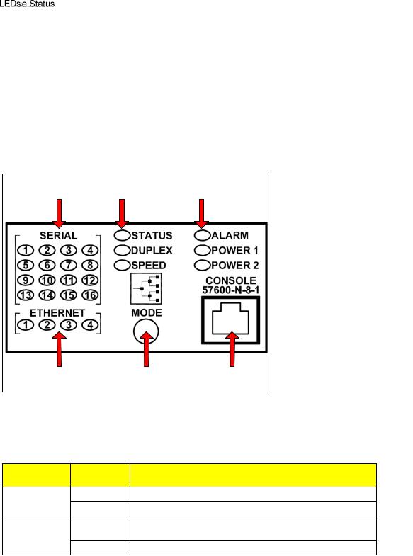
1.3 Display Panel Description
The RS416 is equipped with a versatile display panel, shown in Figure 1, which is designed to provide quick status information for each port, as well as the entire device to allow for simple diagnostics and troubleshooting. It features:
RS232 console port for ‘out of band’ console access and configuration
Power supply and Alarm status indicators
Convenient port status indicators conveying Link-Activity, Duplex, or Speed via push-button control.
System reset via push-button if held for 5 seconds
Figure 1: RS416 LED Display Panel
Device status LEDs exist to provide a quick visual indicator to operators for operational status of the unit. Table 1 defines the possible LED colors and the corresponding description.
LED |
Color |
Description |
|
Power 1 / 2 |
Green |
Power supply operating normal |
|
Red |
Power supply failure |
||
|
|||
|
Red |
Alarm exist – login to console to determine alarm |
|
Alarm |
|
code |
|
|
Off |
No alarms exist |
Table 1: LED Display – Device status LED behavior definition
The port-based LEDs can be cycled between three display modes: Status, Duplex, and Speed. Pushing the mode button causes the display mode to be cycled. Table 2 defines the possible port LED colors and the corresponding description.
RuggedCom® |
10 |
RuggedServer™ RS416 Family Installation Guide rev118 |
Product Overview
Mode |
Color |
Ethernet Port |
Serial Port Status |
|
Status LEDs |
LEDs |
|||
|
|
|||
|
Green (Solid) |
Link |
- |
|
Status |
Green (Blinking) |
Activity |
Traffic |
|
|
Off |
No link |
No Traffic |
|
|
Green (Solid) |
Full-Duplex |
Full-Duplex |
|
Duplex |
Orange (Solid) |
Half-Duplex |
Half-Duplex |
|
|
Off |
No link |
No link |
|
|
Green Blinking |
- |
> 57600 bps |
|
|
Green (Solid) |
100Mbps |
> 19200 bps, |
|
Speed |
|
|
≤ 57600 bps |
|
|
Orange (Solid) |
10 Mbps |
≤ 19200 bps |
|
|
Off |
No link |
No link |
Table 2: LED Display - Port LED behavior definition
RuggedCom® |
11 |
RuggedServer™ RS416 Family Installation Guide rev118 |

Installation
2 Installation
2.1 Mounting
The RS416 has been designed with maximum mounting and display flexibility. Customers can order an RS416 that can be mounted in a standard 19” rack, 1” DIN Rail, or directly onto a panel. For rack mount installations, the RS416 can be ordered with connectors on the front of the unit, or located on the rear of the chassis to allow for all data and power cabling to be installed and connected at the rear of the rack. See Figure 2 for rack mount orientation examples.
Figure 2: Rack mount chassis orientation options – Front and rear mount.
RuggedCom® |
12 |
RuggedServer™ RS416 Family Installation Guide rev118 |
Installation
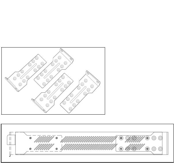
2.1.1 Rack Mounting
The RS416 can be rack mounted using the included rack mount adapter assemblies shown in Figure 3. Secure the one rack mount adapter to the front of each side of the chassis using the included black PAN head Phillips screws in the positions shown in Figure 4. The entire chassis can then be mounted to a standard 19” rack. An additional two rack mount adapters are included to optionally secure the rear of the chassis in highvibration, or seismically active locations.
Figure 3: 19” Rack Mount Adapters
Figure 4: Rack mount adapter mounting location
NOTE: Since heat within the RS416 is channeled to the enclosure, it is recommended that 1 rack unit of space (1.75”) be kept unpopulated and free of equipment above each RS416 product to allow for a small amount of convectional airflow. Although forced airflow is not necessary, any increase in airflow will result in a reduction of ambient temperature that will improve long-term reliability of all equipment mounted within the rack space.
RuggedCom® |
13 |
RuggedServer™ RS416 Family Installation Guide rev118 |
 Loading...