


RuggedSwitch RS969
Installation Guide
www.ruggedcom.com
RuggedCom Inc. I 30 Whitmore Road, Woodbridge, Ontario, Canada L4L 7Z4 Tel: 905-856-5288 I Fax: 905-856-1995 I Toll Free: 1-888-264-0006
Federal Communications Commission Radio Frequency
Interference Statement
This equipment has been tested and found to comply with the limits for a Class A digital device pursuant to Part 15 of the FCC Rules. These limits are designed to provide reasonable protection against harmful interference when the equipment is operated in a commercial environment. This equipment generates, uses and can radiate radio frequency energy and, if not installed and used in accordance with the instruction manual, may cause harmful interference to radio communications. Operation of this equipment in a residential area is likely to cause harmful interference in which case the user will be required to correct the interference on his own expense.
Warning:
Changes or modifications not expressly approved by RuggedCom Inc. could void the user’s authority to operate the equipment.
Caution:
This product contains a laser system and is classified as a “CLASS 1 LASER PRODUCT”.
Caution – Use of controls or adjustments or performance of procedures other than those specified herein may result in hazardous radiation exposure. This product contains no user serviceable parts. Attempted service by unauthorized personnel shall render all warranties null and void.
Should this device require service see the “Warranty and Service” section of this installation guide.
Important:
The RS969 family of products should be installed in a restricted access location where access can only be gained by service personnel or users who have been instructed about the reasons for the restrictions applied to the location and about any precautions that shall be taken; and access is through the use of a tool or lock and key, or other means of security, and is controlled by the authority responsible for the location.
Trademarks:
Ethernet is a trademark of Xerox Corporation
RuggedSwitch, RuggedRated, ROS and eRSTP are trademarks of RuggedCom® Inc.
2
2008 RuggedCom Inc. All rights reserved |
Rev104 |
Table of Contents
1 |
Product Overview ..................................................................................................................... |
4 |
||
|
1.1 |
|
RS969 Family Ports/Connectors Description.................................................................. |
5 |
2 |
Installation ................................................................................................................................ |
7 |
||
|
2.1 |
|
DIN Rail Mounting........................................................................................................... |
7 |
|
2.2 |
|
Ingress Protection IP67 .................................................................................................. |
8 |
|
2.3 |
|
Power Supply Wiring and Grounding .............................................................................. |
9 |
|
2.3.1 Power Supply Input Connectors Description .............................................................. |
9 |
||
|
2.3.2 Single AC Power Supply Wiring Examples............................................................... |
12 |
||
|
2.3.3 Single DC Power Supply Wiring Examples .............................................................. |
13 |
||
|
2.3.4 Dual Power Supplies – DC and AC Inputs ............................................................... |
14 |
||
|
2.4 |
|
Dielectric Strength (HIPOT) Testing ............................................................................. |
16 |
|
2.5 |
|
Failsafe Alarm Relay Wiring and Specifications............................................................ |
17 |
|
2.6 |
|
Console Port Wiring...................................................................................................... |
18 |
|
2.7 |
|
Fast Ethernet Ports – Signal Description ...................................................................... |
19 |
3 |
Technical Specifications ......................................................................................................... |
20 |
||
|
3.1 |
|
Operating Environment ................................................................................................. |
20 |
|
3.2 |
|
Power Supply Specifications......................................................................................... |
20 |
|
3.3 |
|
Failsafe Relay Specifications ........................................................................................ |
20 |
|
3.4 |
|
Twisted Pair Data Port Specifications ........................................................................... |
21 |
|
3.5 |
|
Fiber Optical Port Specifications................................................................................... |
21 |
|
3.6 |
|
IEC 61850-3 Type Tests ............................................................................................... |
22 |
|
3.7 |
|
IEEE 1613 Type Tests.................................................................................................. |
23 |
|
3.8 |
|
IEC Environmental Type Tests ..................................................................................... |
23 |
|
3.9 |
|
Mechanical Specifications ............................................................................................ |
24 |
|
3.10 |
Agency Approvals......................................................................................................... |
26 |
|
4 |
Accessories ............................................................................................................................ |
27 |
||
|
4.1 |
POWER (1/unit) ................................................................................................................... |
27 |
|
|
4.2 |
CONSOLE (1/unit) ............................................................................................................... |
27 |
|
|
4.3 |
FAILSAFE (1/unit)................................................................................................................ |
28 |
|
|
4.4 |
ETHERNET (8/unit) ............................................................................................................. |
29 |
|
|
4.5 LC FIBER OPTIC (2/unit)..................................................................................................... |
30 |
||
5 |
Warranty................................................................................................................................. |
31 |
||
3
2008 RuggedCom Inc. All rights reserved |
Rev104 |
1 Product Overview
The RuggedSwitch™ RS969 is an industrially hardened, fully managed Ethernet switch providing dual fiber optical Gigabit Ethernet ports and eight Fast Ethernet copper ports in an IP65/IP67 rated package for protection against low pressure jets of water (IP65) or temporary immersion in water (IP67). Designed to operate reliably in harsh industrial environments the RS969 provides a high level of immunity to electromagnetic interference and heavy electrical surges typical of environments found in electric utility substations, factory floors or in curb side traffic control cabinets. An operating temperature range of -40°C to +85°C coupled with hazardous location certification and IP65/IP67 rated waterproof packaging allows the RS969 to be placed in virtually any location. The embedded Rugged Operating System (ROS™) provides advanced networking features such as Enhanced Rapid Spanning Tree (eRSTP™), Port Rate Limiting and a full array of intelligent functionality for high network availability and manageability.
Ethernet Ports
•2 - Fiber Optical Gigabit Ethernet Ports (1000BaseX) with:.IP65/IP67 Rated fiber optical connectors (type LC)
•8 - Fast Ethernet Ports (10/100BaseTX) with IP65/IP67 Rated M12 D-code connectors or IP65/IP67 Rated shrouded RJ45 style connectors
•Full compliance with IEEE: 802.3, 802.3u and 802.3z
•Non-blocking, store and forward switching
•Full duplex operation and flow control (IEEE 802.3x)
RuggedRated™ for Reliability in Harsh Environments
•IP67 Rated for protection against immersion in water
•IP66 Rated for protection against high pressure jets of water
•Meets IEEE 1613 (electric utility substations)
•Exceeds IEC 61850-3
(electric utility substations)
•Exceeds IEEE 61800-3 (variable speed drive systems)
•Exceeds IEC 61000-6-2 (generic industrial environment)
•Exceeds NEMA TS-2
(traffic control equipment)
•-40 to +85°C operating temperature (no fans)
•Conformal coated circuit boards (optional)
Universal Power Supply Options
•Fully integrated power supply
•Universal high-voltage range: 88-300VDC or 85-264VAC• Popular low-voltage DC ranges: 12, 24, 48 VDC
•Dual redundant, parallel load-sharing power supplies (option)
•Can be powered from different sources for ultimate redundancy
•Available with M12 or M23 style connectors
•CSA/UL 60950 safety approved to +85°C
Simple Plug and Play Operation
•Automatic learning of up to 8192 MAC addresses
•Auto-negotiation on all 10/100BaseTX ports
•Auto-MDI/MDIX (crossover) on all 10/100BaseTX ports
•LED indicators for link and activity
ROS™ Advanced Network Management
•Enhanced Rapid Spanning Tree (eRSTPTM)
•Quality of Service (802.1p) for real-time traffic
•Port rate limiting: 128kbps to 8Mbps
•VLAN (802.1q) with double tagging
•IGMP Snooping for multicast filtering
•Port configuration, status, statistics, mirroring, security
•Loss of link management on fiber ports
•Web-based, Telnet, CLI management interfaces
•SNMP v2 and RMON
•Rich set of diagnostics with logging and alarms
4
2008 RuggedCom Inc. All rights reserved |
Rev104 |

1.1 RS969 Family Ports/Connectors Description
Figure 1.1.1 RS969–M12 with Mini-Change Power Connector
|
5 |
2008 RuggedCom Inc. All rights reserved |
Rev104 |

Figure 1.1.2 RS969–RJ45 with M23 Power Connector
ITEM |
Activity |
Comments |
LINK LED (Yellow) |
Solid |
Link Established |
|
Blinking |
Tx/Rx Activity |
Power 1 LED |
Solid |
Power Supply 1 On |
Power 2 LED |
Solid |
Power Supply 2 On |
Alarm LED (Red) |
Solid |
Alarm condition exists |
|
6 |
2008 RuggedCom Inc. All rights reserved |
Rev104 |
2 Installation
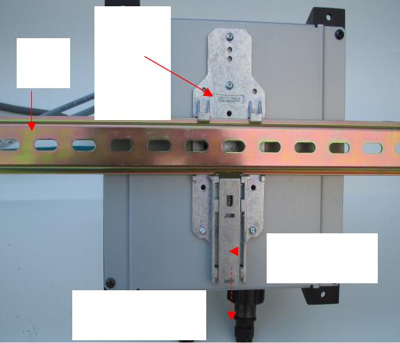
2.1 DIN Rail Mounting
An optional DIN rail mounting bracket is available for the RS969. Figure 2.1.1 details mounting instructions for the standard 1” DIN Rail.
Optional
DIN
DIN Rail
Rail
Mounting
Bracket
Release
Latch
Release Direction
Figure 2.1.1 RS969 Family DIN Rail Mounting
7
2008 RuggedCom Inc. All rights reserved |
Rev104 |
2.2 Ingress Protection IP67
IEC International Standard 60529 (Edition 2.1: 2001-02) is a "classification of degrees of protection provided by enclosures as a system for specifying the enclosures of electrical equipment on the basis of the degree of protection provided by the enclosure." These ratings are determined by specific tests
The IP number is composed of two numbers, the first referring to the protection against solid objects and the second against liquids. The higher the IP number, the better the protection. The chart below defines levels of IP ratings.
|
1st |
|
Degree of protection against access to |
|
2nd |
|
Degree of protection against the |
|
|
|
|
||||
|
IP# |
|
hazardous parts & ingress of solid objects |
|
IP# |
|
ingress of water |
0 |
|
No protection |
0 |
|
No protection |
||
|
|
|
|
|
|
|
|
1 |
|
Protected against solid foreign objects of 50 mm Ø |
1 |
|
Protected against vertically falling water drops |
||
|
and > |
|
|||||
|
|
|
|
|
|
|
|
|
|
|
|
|
|
|
|
2 |
|
Protected against solid foreign objects of 12.5 mm Ø |
2 |
|
Protected against vertically falling water drops |
||
|
and > |
|
when enclosure titled up 15° |
||||
|
|
|
|
|
|
||
|
|
|
|
|
|
|
|
3 |
|
Protected against solid foreign objects of 2.5 mm Ø |
3 |
|
Protected against spraying water |
||
|
and > |
|
|||||
|
|
|
|
|
|
|
|
|
|
|
|
|
|
|
|
4 |
|
Protected against solid foreign objects of 1.0 mm Ø |
4 |
|
Protected against splashing water |
||
|
and > |
|
|||||
|
|
|
|
|
|
|
|
|
|
|
|
|
|
||
5 |
|
Dust protected |
5 |
|
Protected against jet-water |
||
|
|
|
|
|
|
||
6 |
|
Dust tight |
6 |
|
Protected against strong jet-water |
||
|
|
|
|
|
|
|
|
|
|
|
|
7 |
|
Protected against the effects of temporary |
|
|
|
|
|
|
|||
|
|
|
|
|
submersion in water |
||
|
|
|
|
|
|
|
|
|
|
|
|
|
|
|
|
|
|
|
|
8 |
|
Protected against the effects of permanent |
|
|
|
|
|
|
submersion in water |
||
|
|
|
|
|
|
|
|
|
|
|
|
|
|
|
|
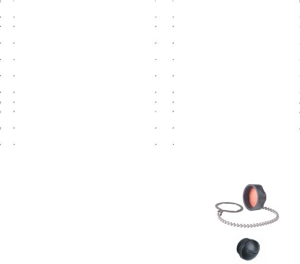
The RuggedCom M969 Industrial Ethernet Switch is manufactured and tested to IP67 standards. With an IP67 rating a product will be "dust tight" and remain completely sealed when immersed in water to a depth of 1 meter for 1 hour. (IEC 60529)
These caps completely seals off unused ports on the IP67 Industrial Ethernet Switch. It has an IP67 rated seal that keeps out all contaminants like dirt, oil, and water.
8
2008 RuggedCom Inc. All rights reserved |
Rev104 |
2.3 Power Supply Wiring and Grounding
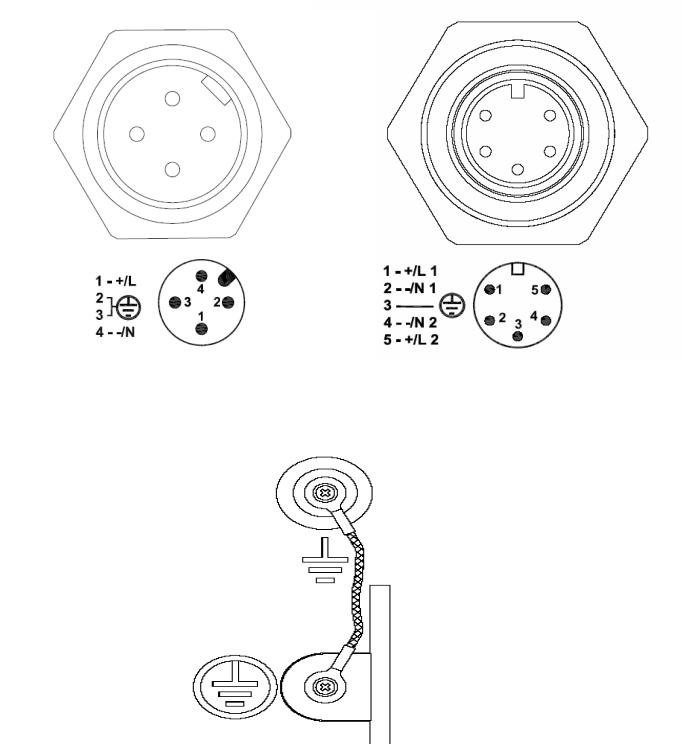
2.3.1 Power Supply Input Connectors Description
Mini power supply connector |
|
M23 power supply connector |
Figure 2.2.1.1 RS969 Family Power Supply Inputs
S u r g e
G r o u n d
C h a s s i s
G r o u n d
Figure 2.2.1.2 RS969 Family Surge Ground / Chassis Ground Connection
9
2008 RuggedCom Inc. All rights reserved |
Rev104 |

The RS969 family has 2 different power supply input connectors---Mini A-coded male connector or M23 A-code male connector shown in Figure 2.2.1.1. The Mini power connector only has 4 terminals, so only one power supply source is allowed to connect to the RS969 with Mini power connector; The M23 power connector has 5 terminal pins which means 2 power supply sources are allowed to power the RS969 with M23 power connector.
The RS969 family supports dual redundant power supplies – “Power Supply 1 (PS1)” and “Power Supply 2 (PS2)”. The connections for PS1, PS2 are shown in Table1 and 2.
Refer to
Table 1 and 2 for a description of each terminal and sections 2.3.2 through 2.3.4 for wiring examples.
Terminal # |
|
|
Description |
|
Usage |
|
|
|
|
|
|
|
|
|
|
|
|
|
|
PS1 Live / + is connected to the positive (+) terminal if the |
1 |
|
|
PS1 |
Live / + |
|
power source is DC or to the (Live) terminal if the power |
|
|
|
|
|
|
source is AC. |
|
|
|
|
|
|
PS1 Neutral / - is connected to the negative (-) terminal if |
2 |
|
|
PS1 |
Neutral / - |
|
the power source is DC or to the (Neutral) terminal if the |
|
|
|
|
|
|
power source is AC. |
|
|
|
|
|
|
Chassis Ground is connected to the Safety Ground |
|
|
|
|
|
|
terminal for AC inputs or the equipment ground bus for DC |
|
|
|
Chassis |
|
inputs. This terminal 3 is connected to chassis ground |
|
3 |
|
|
|
internally in the RS969 family. There is also an additional |
||
|
|
Ground |
|
|||
|
|
|
|
chassis ground screw and the chassis ground connects to |
||
|
|
|
|
|
|
|
|
|
|
|
|
|
both power supply surge grounds via a removable jumper |
|
|
|
|
|
|
shown in Figure 2.2.1.2 . |
4 |
|
|
|
|
|
PS2 Live / + is connected to the positive (+) terminal if the |
|
|
PS2 Live / + |
|
power source is DC or to the (Live) terminal if the power |
||
|
|
|
|
|||
|
|
|
|
|
|
source is AC. |
5 |
|
|
|
|
|
PS2 Neutral / - is connected to the negative (-) terminal if |
|
|
PS2 Neutral / - |
|
the power source is DC or to the (Neutral) terminal if the |
||
|
|
|
|
|||
|
|
|
|
|
|
power source is AC. |
Table 1: RS969 Power terminal block connection description for M23 A-code male connector
|
10 |
2008 RuggedCom Inc. All rights reserved |
Rev104 |
 Loading...