


 Loading...
RuggedBackbone™
RX5000
Hardware Installation Guide
Revision 106 - June 2, 2011
www.RuggedCom.com

RuggedBackbone™ RX5000
RuggedBackbone™ RX5000: Hardware Installation Guide
Copyright © 2011 RuggedCom Inc.
All Rights Reserved
Dissemination or reproduction of this document, or evaluation and communication of its contents, is not authorized except where expressly permitted. Violations are liable for damages. All rights are reserved, particularly for the purposes of patent application or trademark registration.
This document contains proprietary information, which is protected by copyright. All rights are reserved. No part of this document may be photocopied, reproduced or translated to another language without the prior written consent of RuggedCom Inc.
Disclaimer Of Liability
We have checked the contents of this manual against the hardware and software described. However, deviations from the description cannot be completely ruled out.
RuggedCom shall not be liable for any errors or omissions contained herein or for consequential damages in connection with the furnishing, performance, or use of this material.
The information given in this document is reviewed regularly and any necessary corrections will be included in subsequent editions. We appreciate any suggested improvements. We reserve the right to make technical improvements without notice.
Registered Trademarks
ROX™, RuggedBackbone™, RuggedRated™ and eRSTP™ are trademarks of RuggedCom Inc. Other designations in this manual might be trademarks whose use by third parties for their own purposes would infringe the rights of the owner.
Linux® is the registered trademark of Linus Torvalds in the U.S. and other countries.
The registered trademark Linux® is used pursuant to a sublicense from LMI, the exclusive licensee of Linus Torvalds, owner of the mark on a world-wide basis.
Warranty
Five (5) years from date of purchase, return to factory. For warranty details, visit www.ruggedcom.com or contact your customer service representative.
Contacting RuggedCom
Corporate Headquarters |
US Headquarters |
Europe Headquarters |
|
|
|
RuggedCom Inc. |
RuggedCom |
RuggedCom |
300 Applewood Cres., Unit 1, |
1930 Harrison St., Suite 209 |
Unit 41, Aztec Centre, |
Concord, Ontario |
Hollywood, Florida |
Aztec West, Almondsbury, Bristol |
Canada, L4K 5C7 |
USA, 33020 |
United Kingdom BS32 4TD |
Tel: +1 905 856 5288 |
Tel: +1 954 922 7938 ext.103 |
Tel: +44 1454 203 404 |
Fax: +1 905 856 1995 |
Fax: +1 954 922 7984 |
Fax: +44 1454 203 403 |
Toll-free: 1 888 264 0006 |
Toll-free: 1 888 264 0006 |
|
|
|
|
|
Email: RuggedSales@RuggedCom.com |
|
|
|
|
|
|
|
Technical Support |
|
|
|
|
|
Toll Free (North America): 1 866 922 7975 |
|
|
International: +1 905 856 5288 |
|
|
Email: Support@RuggedCom.com |
|
|
|
|
|
Web: www.RuggedCom.com |
|
|

RuggedBackbone™ RX5000 |
|
Table of Contents |
|
FCC Statement And Cautions ......................................................................................................... |
6 |
1. Product Overview ........................................................................................................................ |
7 |
1.1. Functional Overview .......................................................................................................... |
7 |
1.2. Feature Highlights ............................................................................................................. |
7 |
2. RuggedBackbone™ Modules . ..................................................................................................... |
9 |
2.1. Installing A Module In The Chassis .................................................................................. |
9 |
2.2. Control Module ................................................................................................................ |
10 |
2.3. Switch Module ................................................................................................................. |
11 |
2.4. Line Modules ................................................................................................................... |
12 |
2.5. Power Module ................................................................................................................. |
13 |
3. Installation .................................................................................................................................. |
14 |
3.1. Mounting .......................................................................................................................... |
14 |
3.1.1. Rack Mounting ..................................................................................................... |
14 |
3.1.2. Panel Mounting .................................................................................................... |
21 |
3.2. Power Supply Wiring And Grounding ............................................................................. |
22 |
3.2.1. DC Power Supply Wiring ..................................................................................... |
23 |
3.2.2. AC Power Supply Wiring ..................................................................................... |
23 |
3.3. Critical Alarm Relay ........................................................................................................ |
25 |
3.4. Serial Console Ports ....................................................................................................... |
26 |
3.5. Copper Ethernet Ports .................................................................................................... |
27 |
3.5.1. RJ45 Twisted-Pair Copper Ports .......................................................................... |
27 |
3.5.2. Gigabit Ethernet 1000Base-TX Cabling Recommendations ................................. |
27 |
3.5.3. Transient Suppression ......................................................................................... |
28 |
3.6. Fiber Ethernet Ports ........................................................................................................ |
28 |
4. Technical Specifications ............................................................................................................ |
29 |
4.1. Power Supply Specifications ........................................................................................... |
29 |
4.2. Critical Alarm Relay Specifications ................................................................................. |
29 |
4.3. Copper Ethernet Port Specifications ............................................................................... |
29 |
4.4. Fiber Ethernet Port Specifications .................................................................................. |
30 |
4.4.1. Fast Ethernet (100Mbps) Optical Specifications .................................................. |
30 |
4.4.2. Gigabit Ethernet (1Gbps) Optical Specifications .................................................. |
30 |
4.5. Operating Environment ................................................................................................... |
31 |
4.6. Mechanical Specifications ............................................................................................... |
31 |
5. EMI And Environmental Type Tests .......................................................................................... |
32 |
6. Agency Approvals ...................................................................................................................... |
34 |
7. Warranty ..................................................................................................................................... |
35 |
RuggedCom® RuggedBackbone™ |
3 |
RX5000 Installation Guide Rev106 |

RuggedBackbone™ RX5000 |
|
List of Figures |
|
2.1. Chassis Slot Assignment .......................................................................................................... |
9 |
2.2. Control Module ....................................................................................................................... |
10 |
2.3. Switch Module - No Ports ...................................................................................................... |
11 |
2.4. Switch Module - Fiber (LC) .................................................................................................... |
11 |
2.5. Switch Module - Copper ......................................................................................................... |
11 |
2.6. 16TX01 - 16 RJ45 Ports ........................................................................................................ |
12 |
2.7. 8FX11 - 8 LC Fiber Ports ....................................................................................................... |
12 |
2.8. Power Supply Module ............................................................................................................. |
13 |
3.1. Rack Mount Assembly Step 1 ................................................................................................ |
14 |
3.2. Rack Front Mount - Front View .............................................................................................. |
15 |
3.3. Rack Front Mount - Side View ............................................................................................... |
15 |
3.4. Rack Front Mount - Top View ................................................................................................ |
16 |
3.5. Rack Front Mount with Front-Mount Power Supplies - Front View ......................................... |
17 |
3.6. Rack Front Mount with Front-Mount Power Supplies - Side View .......................................... |
17 |
3.7. Rack Front Mount with Front-Mount Power Supplies - Top View ........................................... |
18 |
3.8. Rack Rear Mount - Rear View ............................................................................................... |
19 |
3.9. Rack Rear Mount - Side View ................................................................................................ |
19 |
3.10. Rack Rear Mount - Top View ............................................................................................... |
20 |
3.11. Panel Mount - Side View ...................................................................................................... |
21 |
3.12. RX5000 Power Connector .................................................................................................... |
22 |
3.13. DC Power Connection .......................................................................................................... |
23 |
3.14. AC Power - Integrated Earth Connection ............................................................................. |
23 |
3.15. AC Power - Separate Earth Connection ............................................................................... |
24 |
3.16. Critical Alarm Relay Connection ........................................................................................... |
25 |
3.17. Serial Console Port ............................................................................................................... |
26 |
3.18. RJ45 Ethernet Jack .............................................................................................................. |
27 |
3.19. LC ......................................................................................................................................... |
28 |
3.20. MTRJ ..................................................................................................................................... |
28 |
3.21. SC ......................................................................................................................................... |
28 |
3.22. ST ......................................................................................................................................... |
28 |
RuggedCom® RuggedBackbone™ |
4 |
RX5000 Installation Guide Rev106 |

RuggedBackbone™ RX5000 |
|
List of Tables |
|
3.1. RX5000 Power Connector Pinout ........................................................................................... |
22 |
3.2. RX5000 Critical Alarm Relay Connector Pinout ..................................................................... |
25 |
3.3. Serial Console Pinout ............................................................................................................. |
26 |
3.4. RJ45 Ethernet Pinout ............................................................................................................. |
27 |
3.5. Cabling Categories And 1000Base-TX Compliance ............................................................... |
27 |
3.6. Available Fiber Connector Types ........................................................................................... |
28 |
4.1. Power Supply Specifications .................................................................................................. |
29 |
4.2. Critical Alarm Relay Specifications ......................................................................................... |
29 |
4.3. Copper Ethernet Port Specifications ....................................................................................... |
29 |
4.4. Fast Ethernet (100Mbps) Optical Specifications ..................................................................... |
30 |
4.5. Gigabit Ethernet (1Gbps) Optical Specifications ..................................................................... |
30 |
4.6. Operating Environment ........................................................................................................... |
31 |
4.7. Mechanical Specifications ....................................................................................................... |
31 |
5.1. IEC 61850-3 EMI Type Tests ................................................................................................. |
32 |
5.2. IEEE 1613 (C37.90.x) EMI Immunity Type Tests ................................................................... |
33 |
5.3. Environmental Type Tests ...................................................................................................... |
33 |
6.1. Agency Approvals ................................................................................................................... |
34 |
RuggedCom® RuggedBackbone™ |
5 |
RX5000 Installation Guide Rev106 |
FCC Statement And Cautions
FCC Statement And Cautions
Federal Communications Commission Radio Frequency Interference
Statement
This equipment has been tested and found to comply with the limits for a Class A digital device pursuant to Part 15 of the FCC Rules. These limits are designed to provide reasonable protection against harmful interference when the equipment is operated in a commercial environment. This equipment generates, uses and can radiate radio frequency energy and, if not installed and used in accordance with the instruction manual, may cause harmful interference to radio communications. Operation of this equipment in a residential area is likely to cause harmful interference in which case the user will be required to correct the interference on his own expense.
CAUTION: LASER
This product contains a laser system and is classified as a CLASS 1 LASER PRODUCT. Use of controls or adjustments or performance of procedures other than those specified herein may result in hazardous radiation exposure.
CAUTION: Service
This product contains no user-serviceable parts. Attempted service by unauthorized personnel shall render all warranties null and void.
Changes or modifications not expressly approved by RuggedCom Inc. could invalidate specifications, test results, and agency approvals, and void the user's authority to operate the equipment.
Should this device require service, please refer to Chapter 7, Warranty in this guide.
CAUTION: Physical Access
This product should be installed in a restricted access location where access can only be gained by service personnel or users who have been instructed about the reasons for the restrictions applied to the location and about any precautions that shall be taken; and access is through the use of a tool or lock and key, or other means of security, and is controlled by the authority responsible for the location.
CAUTION: Hot Surface
Avoid contact with the surface of the unit. The metal surface may be hot due to the high allowable ambient temperature per specification.
ATTENTION: Surface Chaude
Éviter tout contact avec la surface. La surface métallique peut être chaude a cause d'une température ambiante élevée selon les spécifications. S.V.P. se référer à la version française de ce guide pour les détails.
RuggedCom® RuggedBackbone™ |
6 |
RX5000 Installation Guide Rev106 |

1. Product Overview
1. Product Overview
1.1. Functional Overview
The RuggedBackbone™ RX5000 is a high-port density routing and switching platform, designed to operate in harsh environments. The RX5000 can withstand high levels of electromagnetic interference, radio frequency interference, and a wide temperature range of -40°C to +85°C. This platform is designed to meet the challenging climatic and environmental demands found in utility, industrial and military network applications.
The RX5000’s superior ruggedized hardware design, coupled with the embedded ROX™ operating system provides improved system reliability when your network needs it the most. The cyber security and networking features make it ideally suited for creating secure Ethernet networks for mission critical, real-time, control applications.
The RX5000 is a scalable, hot-swappable, modular platform which provides its users with the ability to change the RuggedBackbone™ as their network grows or their needs change.
The RuggedEnclosure™ is rated for IP65 ingress protection, meaning that it is dust tight and can withstand water from a nozzle in any direction. Constructed with aluminum extrusions with fins on both sides combined with high reliability internal circulation fans optimizes heat transfer without exchange of outside air and improves MTBF for the enclosed electronics.
The combination of the RuggedEnclosure™ and the MX5000 RuggedBackbone™ provides an extremely flexible package that has MIL-STD approvals and continues RuggedCom’s tradition of pioneering advanced networking solutions specifically for the harsh environments found in military applications.
1.2. Feature Highlights
Ethernet Ports
•Up to 96 10/100TX + 2 10/100/1000TX copper ports
•Up to 48 100FX optical ports
•Up to 2 Gigabit Ethernet ports
•Long-haul optics allow distances up to 90km
•Multiple connector types (ST, MTRJ, LC, SC)
Cyber Security Features
•Multi-level passwords
•SSH/SSL encryption
•Enable/disable ports, MAC based port security
•Port based network access control (802.1x)
•VLAN (802.1Q) to segregate and secure network traffic
RuggedRated™ for Reliability in Harsh Environments
•Immunity to EMI and high voltage electrical transients:
•Zero-Packet-Loss Technology
RuggedCom® RuggedBackbone™ |
7 |
RX5000 Installation Guide Rev106 |

1. Product Overview
•Meets IEEE 1613 (electric utility substations)
•Exceeds IEC 61850-3 (electric utility substations)
•Exceeds IEC 61800-3 (variable speed drive systems)
•Exceeds IEC 61000-6-2 (generic industrial environment)
•-40°C to +85°C operating temperature (no fans)
•Conformal coated printed circuit boards (optional)
ROX™ Software Features
•Next Generation of ROX™ (Rugged Operating System on LinuX)
•Simple plug and play operation – automatic learning, negotiation, and crossover detection
•MSTP (Multiple Spanning Tree Protocol - 802.1Q-2005 - formerly 802.1s)
•RSTP (Rapid Spanning Tree protocol - 802.1w) and eRSTP™ (Enhanced Rapid Spanning Tree Protocol) network fault recovery
•QoS (Quality of Service - 802.1p) for real-time traffic
•VLAN (Virtual LAN - 802.1Q) with double tagging and GVRP (GARP VLAN Registration Protocol) support
•GMRP (GARP Multicast Registration Protocol - 802.1D) and GMVP services
•Link aggregation (802.3ad)
•Traffic prioritization
•Transaction based configuration with rollback
•Telecom-style CLI (Command Line Interface)
Management Tools
•Web-based interface
•Telecom-style CLI
•SNMP v1/v2c
•Rich set of diagnostics with configurable logging
•NETCONF
•RBAC (Role-Based Access Control)
Modularity
•Up to 6 slots for line modules
•Up to 96 10/100TX or 48 100FX ports
Universal Power Supply Options
•Fully integrated, dual-redundant (optional) power supplies
•Universal high voltage ranges: 88-300VDC or 85-264VAC
•Terminal blocks for reliable maintenance-free connections
•CSA/UL 60950 safety approved to 85°C
RuggedCom® RuggedBackbone™ |
8 |
RX5000 Installation Guide Rev106 |

2. RuggedBackbone™ Modules
2. RuggedBackbone™ Modules
The RX5000 chassis comprises ten slots, each one of which is designed to accommodate a particular module. Figure 2.1 shows the rear panel view of the RX5000. The slot name at each position (“PM1”, “L1”, etc.) denotes the type of module that may be installed at that position in the chassis.
Figure 2.1. Chassis Slot Assignment
The slot name markings in the diagram above represent the following RuggedBackbone™ modules:
CM
The Control Module is the central processing unit of the system. Refer to Section 2.2: Control Module for detail.
SM
The Switch Module contains the chassis-wide Ethernet switch fabric that interconnects Ethernet ports on all installed line modules. Refer to Section 2.3: Switch Module for detail.
L1..L6
One or more Line Module cards may be installed - refer to Section 2.4: Line Modules for detail.
PM1, PM2
Dual, redundant, power supply modules may be installed - refer to Section 2.5: Power Module for detail.
All supported modules are built to the RuggedRated™ specifications of the RuggedBackbone™ RX5000. Each of the module types is detailed in the following sections.
2.1. Installing A Module In The Chassis
In order to install a module into the RuggedBackbone™ chassis, align the module guide ribs with the channels on the chassis, and push the module in as far as it will go. There is a detent position that must be pushed through to properly seat the connectors - this is the added resistance from the grounding springs. When properly seated, the module flange will rest on the main chassis frame. Tighten the thumbscrews using finger strength only.
RuggedCom® RuggedBackbone™ |
9 |
RX5000 Installation Guide Rev106 |
2. RuggedBackbone™ Modules
2.2. Control Module
The Control Module (CM) is the central processing unit of the RuggedBackbone™ chassis. The ROX™ operating system running on the CM controls and coordinates the functions of all modules installed in the system. The Control Module is installed in the CM slot of the chassis, as shown in Figure 2.1, “Chassis Slot Assignment”.
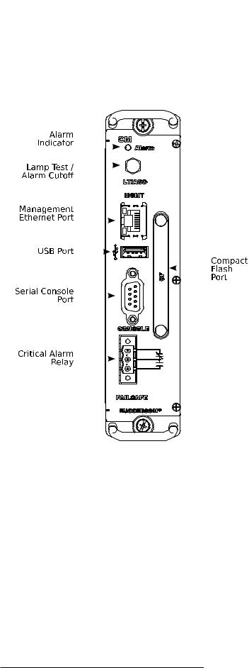
Figure 2.2. Control Module
The CM is equipped with an RS232 serial console port for initial management functions, and a locally connected 10/100Base-T Ethernet port for system management out of band from the switch fabric.
Other features of the CM include:
•Alarm Indicator LED, which indicates system alarm status.
•Removable 1GB Compact Flash (CF) card, which contains active and fallback installations of the ROX™ operating system, along with the configuration database and other system data.
•Critical Alarm Relay, activated by the operating system to indicate a critical alarm.
•Lamp Test / Alarm Cutoff button.
•Utility USB port (as yet unused).
Detailed information on connecting to the ports on the CM can be found in this guide as follows:
RuggedCom® RuggedBackbone™ |
10 |
RX5000 Installation Guide Rev106 |
2.RuggedBackbone™ Modules
•Serial Console: Section 3.4, “Serial Console Ports”
•Management Ethernet Interface: Section 3.5, “Copper Ethernet Ports”
•Critical Alarm (Failsafe) Relay Interface: Section 3.3, “Critical Alarm Relay”
2.3. Switch Module
The Switch Module (SM) is the Ethernet switch fabric central to the RuggedBackbone™ RX5000. It provides one Gbps of bandwidth to each installed Line Module and two 1Gbps ports to (optional) connectors on its own faceplate. The Switch Module is installed in the SM slot of the chassis, as shown in Figure 2.1, “Chassis Slot Assignment”.
Switch Modules may be ordered as separate components with copper, LC fiber, or with no Ethernet ports. Refer to the RuggedBackbone™ RX5000 data sheet for complete ordering details.
Figure 2.3. Switch |
Figure 2.4. Switch |
Figure 2.5. Switch |
Module - No Ports |
Module - Fiber (LC) |
Module - Copper |
RuggedCom® RuggedBackbone™ |
11 |
RX5000 Installation Guide Rev106 |
Loading...