


RX1512
Table of contents
 Loading...
RUGGEDCOM RX1512
Installation Guide
6/2013
FCC Statement And
Cautions
Product Overview
1
RUGGEDCOM Modules
2
Installation
3
Technical Specifications
4
EMI And Environmental Type
Tests
5
Agency Approvals
6
Warranty
7

RUGGEDCOM RX1512
Installation Guide
ii
Copyright © 2013 RuggedCom Inc.
All rights reserved. Dissemination or reproduction of this document, or evaluation and communication of its contents, is not authorized
except where expressly permitted. Violations are liable for damages. All rights reserved, particularly for the purposes of patent application or
trademark registration.
This document contains proprietary information, which is protected by copyright. All rights are reserved. No part of this document may be
photocopied, reproduced or translated to another language without the prior written consent of RuggedCom Inc.
Disclaimer Of Liability
Siemens has verified the contents of this manual against the hardware and/or software described. However, deviations between the product
and the documentation may exist.
Siemens shall not be liable for any errors or omissions contained herein or for consequential damages in connection with the furnishing,
performance, or use of this material.
The information given in this document is reviewed regularly and any necessary corrections will be included in subsequent editions. We
appreciate any suggested improvements. We reserve the right to make technical improvements without notice.
Registered Trademarks
ROX™, Rugged Operating System On Linux™, CrossBow™ and eLAN™ are trademarks of Siemens AG. ROS® is a registered trademark of
Siemens AG.
Other designations in this manual might be trademarks whose use by third parties for their own purposes would infringe the rights of the
owner.
Security Information
Siemens provides automation and drive products with industrial security functions that support the secure operation of plants or machines.
They are an important component in a holistic industrial security concept. With this in mind, our products undergo continuous development.
We therefore recommend that you keep yourself informed with respect to our product updates. Please find further information and newsletters
on this subject at: http://support.automation.siemens.com.
To ensure the secure operation of a plant or machine it is also necessary to take suitable preventive action (e.g. cell protection concept) and
to integrate the automation and drive components into a state-of-the-art holistic industrial security concept for the entire plant or machine.
Any third-party products that may be in use must also be taken into account. Please find further information at: http://www.siemens.com/
industrialsecurity.
Warranty
Siemens warrants this product for a period of five (5) years from the date of purchase, conditional upon the return to factory for maintenance
during the warranty term. This product contains no user-serviceable parts. Attempted service by unauthorized personnel shall render all
warranties null and void. The warranties set forth in this article are exclusive and are in lieu of all other warranties, performance guarantees
and conditions whether written or oral, statutory, express or implied (including all warranties and conditions of merchantability and fitness for
a particular purpose, and all warranties and conditions arising from course of dealing or usage or trade). Correction of nonconformities in the
manner and for the period of time provided above shall constitute the Seller’s sole liability and the Customer’s exclusive remedy for defective
or nonconforming goods or services whether claims of the Customer are based in contract (including fundamental breach), in tort (including
negligence and strict liability) or otherwise.
For warranty details, visit www.RuggedCom.com or contact a Siemens customer service representative.
Contacting Siemens
Address
Siemens AG
Industry Sector
300 Applewood Crescent
Concord, Ontario
Canada, L4K 5C7
Telephone
Toll-free: 1 888 264 0006
Tel: +1 905 856 5288
Fax: +1 905 856 1995
E-mail
ruggedcom.info.i-ia@siemens.com
Web
www.RuggedCom.com

RUGGEDCOM RX1512
Installation Guide
Table of Contents
iii
Table of Contents
FCC Statement And Cautions ............................................................................. v
Chapter 1
Product Overview ................................................................................................ 1
1.1 Functional Overview ..................................................................................................................... 1
1.2 Feature Highlights ........................................................................................................................ 1
Chapter 2
RUGGEDCOM Modules ...................................................................................... 5
2.1 Installing a Module ....................................................................................................................... 5
2.2 Front Panel .................................................................................................................................. 6
2.2.1 Module Status LEDs .......................................................................................................... 7
2.3 Line Modules (LM) ....................................................................................................................... 7
2.3.1 Ethernet - Copper ............................................................................................................. 7
2.3.2 Ethernet - Fiber ................................................................................................................. 8
2.3.3 SFP Modular ..................................................................................................................... 9
2.3.4 WAN ................................................................................................................................. 9
2.3.5 Serial .............................................................................................................................. 10
2.3.6 Cellular Modem ............................................................................................................... 10
2.3.7 DDS - Digital Data Services ............................................................................................. 10
2.3.8 RuggedAPE™ (Appplication Processing Engine) ............................................................... 11
2.4 Power Supply ............................................................................................................................ 11
Chapter 3
Installation .......................................................................................................... 13
3.1 Mounting .................................................................................................................................... 13
3.1.1 RX1512Dimensions ......................................................................................................... 15
3.2 Power Supply Wiring and Grounding ........................................................................................... 17
3.2.1 RX1512 DC Power Connectors ........................................................................................ 17
3.2.2 Chassis Ground Connection ............................................................................................. 17
3.2.3 DC Power Supply Wiring Example ................................................................................... 18
3.3 Critical Alarm Wiring ................................................................................................................... 18
3.4 Serial Console Port .................................................................................................................... 19
3.5 WAN Ports: RJ45 ....................................................................................................................... 19
3.6 WAN Ports: BNC ........................................................................................................................ 20

Table of Contents
RUGGEDCOM RX1512
Installation Guide
iv
3.7 Copper Ethernet Ports ................................................................................................................ 20
3.7.1 RJ45 Twisted-Pair Copper Ports ....................................................................................... 20
3.7.2 M12 Twisted Pair Copper Ports ........................................................................................ 21
3.7.3 Gigabit Ethernet 1000Base-TX Cabling Recommendations ................................................. 21
3.7.4 Transient Suppression ..................................................................................................... 22
3.8 Serial Ports: RJ45 ...................................................................................................................... 22
3.9 DDS Ports: RJ45 ....................................................................................................................... 23
3.10 DDS Rx and Tx LED Indications ............................................................................................... 23
3.11 SFP Optics – Installation, removal, and precautions .................................................................... 24
3.11.1 Module Insertion – SFP .................................................................................................. 25
3.11.2 SFP Module Removal .................................................................................................... 26
3.12 Fiber Ethernet Ports ................................................................................................................. 27
3.13 Cellular Modems ...................................................................................................................... 28
3.13.1 GSM, EDGE, HSPA+ Cellular Modem Card .................................................................... 29
3.13.2 Installing SIM Cards for GSM, EDGE, HSPA+ Cellular Modems ........................................ 30
Chapter 4
Technical Specifications ..................................................................................... 31
4.1 Power Supply Specifications ....................................................................................................... 31
4.2 Critical Alarm Relay Specifications .............................................................................................. 31
4.3 Copper Ethernet Port Specifications ............................................................................................ 31
4.4 Fiber Ethernet Port Specifications ............................................................................................... 32
4.4.1 Fast Ethernet (100Mbps) Optical Specifications ................................................................. 32
4.4.2 Gigabit Ethernet (1Gbps) Optical Specifications ................................................................. 33
4.5 Operating Environment ............................................................................................................... 34
4.6 RuggedAPE™ Specifications ...................................................................................................... 34
4.7 Mechanical Specifications ........................................................................................................... 34
Chapter 5
EMI And Environmental Type Tests .................................................................. 37
Chapter 6
Agency Approvals .............................................................................................. 39
Chapter 7
Warranty ............................................................................................................. 41
RUGGEDCOM RX1512
Installation Guide
FCC Statement And Cautions
v
FCC Statement And Cautions
Federal Communications Commission Radio Frequency Interference Statement
This equipment has been tested and found to comply with the limits for a Class A digital device pursuant to Part
15 of the FCC Rules. These limits are designed to provide reasonable protection against harmful interference
when the equipment is operated in a commercial environment. This equipment generates, uses and can radiate
radio frequency energy and, if not installed and used in accordance with the instruction manual, may cause
harmful interference to radio communications. Operation of this equipment in a residential area is likely to cause
harmful interference in which case the user will be required to correct the interference at his own expense.
CAUTION!
This product contains a LASER system and is classified as a CLASS 1 LASER PRODUCT. Use of
controls or adjustments or performance of procedures other than those specified herein may result in
hazardous radiation exposure.
CAUTION!
This product contains no user-serviceable parts. Attempted service by unauthorized personnel shall
render all warranties null and void.
Changes or modifications not expressly approved by RuggedCom Inc. could invalidate specifications,
test results, and agency approvals, and void the user’s authority to operate the equipment.
Should this device require service, refer to Chapter 7, Warranty in this guide.
CAUTION!
This product should be installed in a restricted access location where access can only be gained by
service personnel or users who have been instructed about the reasons for the restrictions applied to
the location and about any precautions that shall be taken; and access is through the use of a tool or
lock and key, or other means of security, and is controlled by the authority responsible for the location.

RUGGEDCOM RX1512
Installation Guide
FCC Statement And Cautions
vi

RUGGEDCOM RX1512
Installation Guide
Chapter 1
Product Overview
Functional Overview 1
Product Overview
Section 1.1
Functional Overview
The RUGGEDCOM RX1512 is a cost-efficient, rugged layer 3 switch and router. The RX1512’s modular and field
replaceable platform allows you to select WAN, serial, and Ethernet options, making it ideally suited for electric
power utilities, the industrial plant floor, and traffic control systems. The appliance’s compact form factor makes it
ideal for pole mount applications or installation in restricted spaces.
The RX1512 is designed to the RuggedRated™ specification, providing a high level of immunity to
electromagnetic interference (EMI) and heavy electrical surges typical of the harsh environments found in many
industrial applications. An operating temperature range of -40°C to +85°C (-40°F to +185°F) allows the RX1512 to
be placed in almost any location.
Section 1.2
Feature Highlights
Cyber Security Features
• Multi-level passwords
• SSH/SSL encryption
• Enable/disable ports, MAC-based port security
• Port-based network access control (802.1x)
• VLAN (802.1Q) to segregate and secure network traffic
• RADIUS centralized password management
• SNMPv3 encrypted authentication and access security
RuggedRated™ for Reliability in Harsh Environments
• Immunity to EMI and high voltage electrical transients:
○ Zero-Packet-Loss Technology
○ Meets IEEE 1613 (electric utility substations)
○ Exceeds IEC 61850-3 (electric utility substations)
○ Exceeds IEC 61800-3 (variable speed drive systems)
○ Exceeds IEC 61000-6-2 (generic industrial environment)
• -40°C to +85°C operating temperature (no fans)
• Optional conformal coated printed circuit boards
• Failsafe Output Relay: For critical failure or error alarming
Physical Ports
• Field replaceable line modules

Chapter 1
Product Overview
RUGGEDCOM RX1512
Installation Guide
2 Feature Highlights
• Up to 12 ports 100FX
• Up to 12 ports 10/100TX
• Up to 4 ports Gigabit Ethernet
WAN Port Options
• Up to 4 T1/E1 ports via RJ45 connectors (channelized/unchannelized)
• Up to 2 E1 ports via BNC connectors (channelized/unchannelized)
• Cellular/DDS
Serial Ports
• Fully compliant EIA/TIA RS485, RS422, RS232 serial ports (software selectable) with RJ45 connectors
• Raw socket mode support allows conversion of any serial protocol
Protocols
•
WAN
○ Frame Relay RFC 1490 or RFC 1294
○ PPP RFC 1661, 1332, 1321, 1334, PAP, CHAP Authentication
○ Multilink PPP RFC 1990
○ GOOSE messaging support
•
IP
○ Routing: OSPF, BGP, RIPv1, RIPv2
○ VRRP Agent
○ Traffic control, NTP Server, IP Multicast Routing
○ DHCP Agent (Option 82 Capable)
Frame Relay Support
• ISO and ITU compliant, network certified.
• ANSI T1.617 Annex D, Q.933 or LMI Local Signaling
Management Tools
• Web-based, SSH, CLI management interfaces
• SNMP v1, v2, and v3
• Remote Syslog
• Rich set of diagnostics with logging and alarms
• Loopback diagnostic tests
• Raw and interpreted real-time line traces
Universal Power Supply Options
• Non-removable power supply integrated with chassis/cm/unit
• Fully integrated power supplies (no external adaptors)
• Input voltage range: 10-72VDC
• TUV/UL 60950 safety approved to 85°C

RUGGEDCOM RX1512
Installation Guide
Chapter 1
Product Overview
Feature Highlights 3
Warranty
• 5 Year Warranty

RUGGEDCOM RX1512
Installation Guide
Chapter 1
Product Overview
Feature Highlights 4
RUGGEDCOM RX1512
Installation Guide
Chapter 2
RUGGEDCOM Modules
Installing a Module 5
RUGGEDCOM Modules
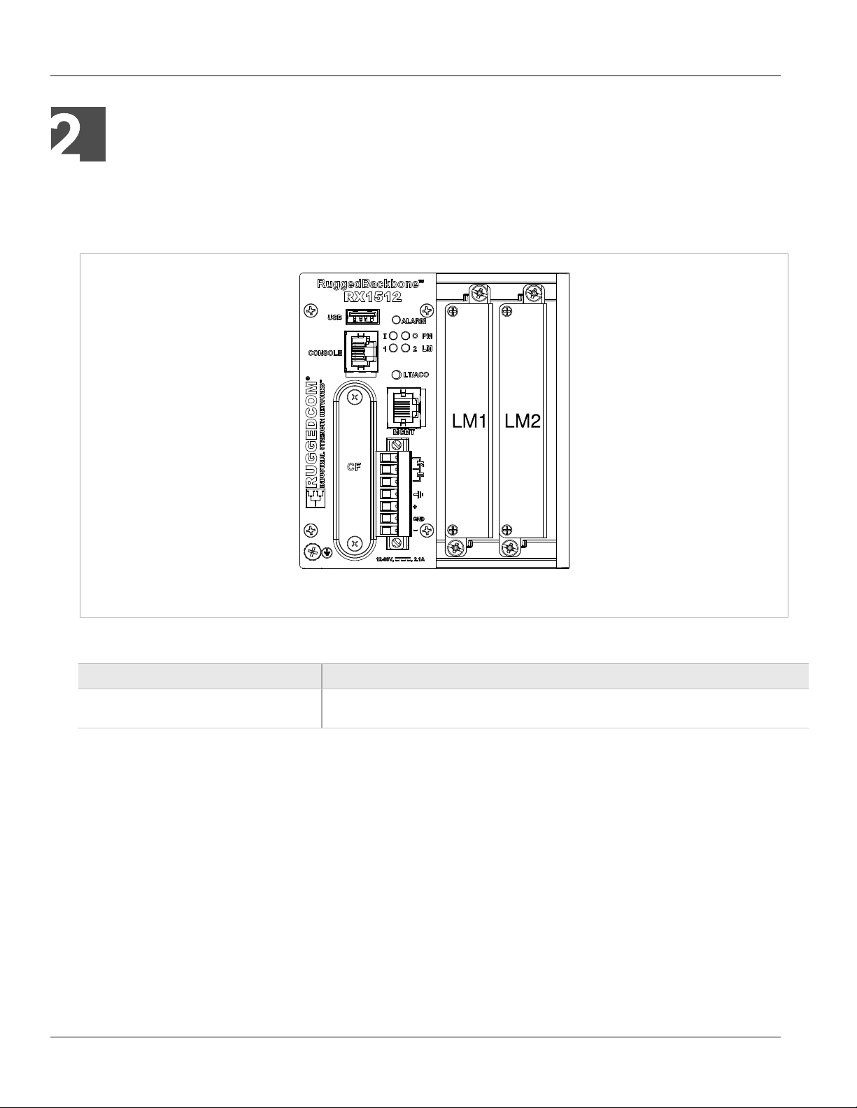
The RX1512 chassis provides two module slots. Each slot accommodates a particular type of RuggedCom
module. Figure 1, “Chassis Slot Assignment” shows the module slots on the RX1512.
Figure 1: Chassis Slot Assignment
The RX1512 chassis supports the following modules:
Parameter Description
LM1 and LM2 The RX1512 chassis supports up to two line module (LM) cards. For more information on line
modules, see Section 2.3, “Line Modules (LM)”.
The RX1512 features a single 12-60VDC power supply integrated with the Control Module. For instructions on
completing the power supply connections, see Section 2.4, “Power Supply”.
All modules are built to the RuggedRated™ specifications of the RUGGEDCOM RX1512. Each module type is
described in the following sections.
Section 2.1
Installing a Module
To install a module into the RUGGEDCOM chassis, align the module guide ribs with the channels on the chassis.
Push the module in as far as it will go, being sure to push through the resistance provided by the grounding
springs. When properly seated, the module flange will rest on the main chassis frame. Tighten the thumbscrews
using finger strength only.
Chapter 2
RUGGEDCOM Modules
RUGGEDCOM RX1512
Installation Guide
6 Front Panel
NOTE
Serial line modules are hot-swappable, meaning they can be removed and installed while the device is
running.
When installing a serial line module while the device is running, make sure internal VLANs are
enabled. For more information about configuring VLANs, refer to the RX1512 User Guide for the
RX1512.
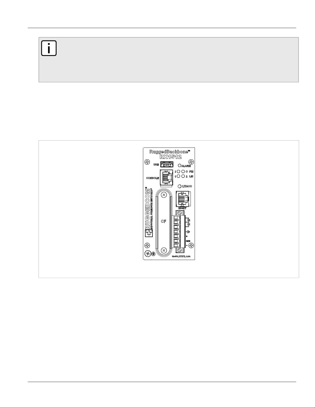
Section 2.2
Front Panel
The RX1512 Front Panel is equipped with an RS232 serial console port for initial management functions, and a
locally connected 10/100Base-T Ethernet port for system management out of band from the switch fabric.
Figure 2: Front View
Other Front Panel features include:
• Utility USB port
• Power module indicator LEDs
• Line module indicator LEDs
• Alarm Indicator LED, which indicates system alarm status.
• Lamp Test / Alarm Cutoff (LT/ACO) button
• Removable 1GB Compact Flash (CF) card, which contains active and fallback installations of the RX1512
operating system, along with the configuration database and other system data
• Chassis ground connection
For more information on connecting to the ports on the front panel, see the following topics:
RUGGEDCOM RX1512
Installation Guide
Chapter 2
RUGGEDCOM Modules
Module Status LEDs 7
• Serial Console: Section 3.4, “Serial Console Port”
• Management Ethernet Interface: Section 3.7, “Copper Ethernet Ports”
• Critical Alarm (Failsafe) Relay Interface: Section 3.3, “Critical Alarm Wiring”
Section 2.2.1
Module Status LEDs
The front panel module status LEDs provide the following information:
Table: Module Status LED Indications
LED Purpose Description
PM Indicates power supply status. I = Power supply is receiving input voltage.
O = Power supply is providing
output voltage to the RX1512.
LM 1 through 2 Indicates the line module status. Green = OK
Orange = Warning alert
Red = Configuration error
Section 2.3
Line Modules (LM)
The RUGGEDCOM RX1512 supports two line modules in slots LM1 through LM2. Several types of line modules
may be ordered, depending on the type, speed and number of Ethernet ports required.
The following illustrations show the typical port configurations and connectors available for RX1512 line modules.
For complete information on the available line modules, refer to the RUGGEDCOM RX1512 data sheet.
NOTE
Only one T1/E1 module may be used per router.
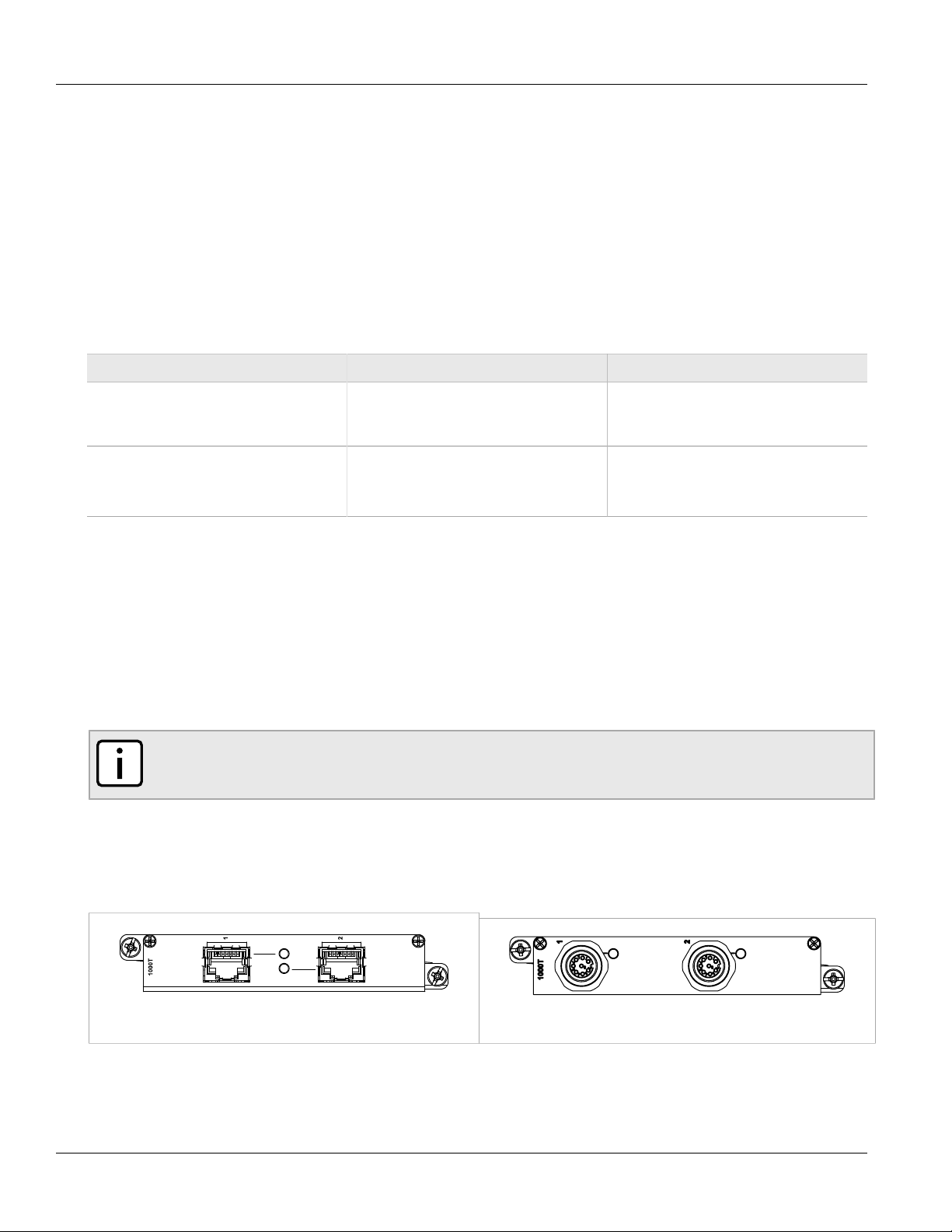
Section 2.3.1
Ethernet - Copper
Figure 3: CG01: 2 × 10/100/1000TX RJ45 Figure 4: CG03: 2 x 8-Pin 10/100/1000TX M12
Chapter 2
RUGGEDCOM Modules
RUGGEDCOM RX1512
Installation Guide
8 Ethernet - Fiber
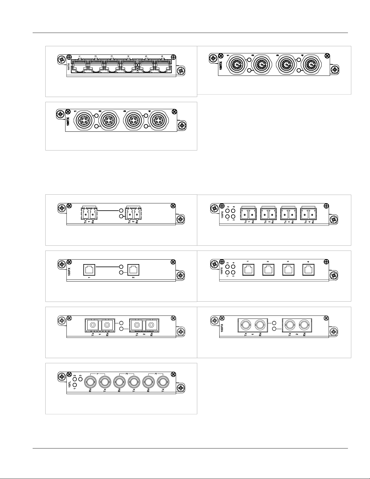
Figure 5: 6TX01: 6 × 10/100TX RJ45
Figure 6: 4TX03: 4 x 8-Pin 10/100TX M12
Figure 7: 4TX04: 4 x 4-Pin 10/100TX M12
Section 2.3.2
Ethernet - Fiber
Figure 8: FX**/FG**: 2 × 100FX/1000SX/1000LX LC Figure 9: 4FX**: 4 × 100FC LC
Figure 10: FX03: 2 × 100 FX MTRJ
Figure 11: 4FX03: 4 × 100FX MTRJ
Figure 12: FX**: 2 × 100FX SC
Figure 13: FX**: 2 × 100FX ST
Figure 14: FL01: 3 × 10FL/100SX
RUGGEDCOM RX1512
Installation Guide
Chapter 2
RUGGEDCOM Modules
SFP Modular 9
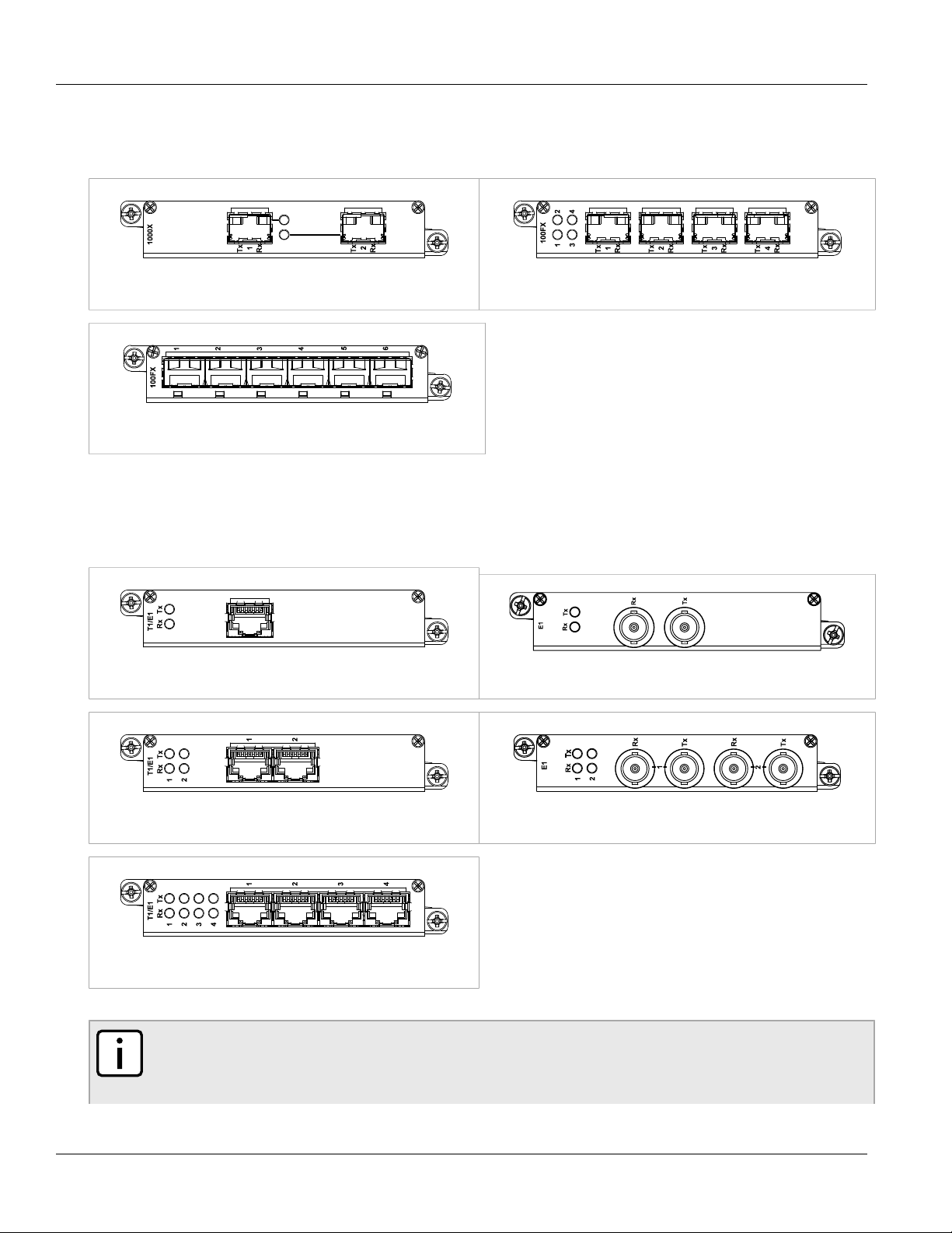
Section 2.3.3
SFP Modular
Figure 15: FG5*: 2 × 1000LX/1000SX SFP Figure 16: FX5*: 4 × 100FX/100LX/100SX SFP
Figure 17: 6FX50: 6 × 100FX SFP
Section 2.3.4
WAN
Figure 18: TC1: 1 × T1/E1 RJ45 Figure 19: E01: 1 × E1 BNC
Figure 20: TC2: 2 × T1/E1 RJ45
Figure 21: E02: 2 × E1 BNC
Figure 22: TC4: 4 × T1/E1 RJ45
NOTE
The TC1, TC2 and TC4 WAN modules comply with Part 68 of the FCC rules and requirements
adopted by ACTA. The product identifier is provided on a label on top of the modules. If requested, this
information must be provided to the telephone company.
Loading...