


Rugged Operating System
(ROS™)
v3.5 User Guide
For use with:
RS400
Release 3.5.0 - June, 2008

Copyright
COPYRIGHT © 2008 RuggedCom Inc. ALL RIGHTS RESERVED
Dissemination or reproduction of this document, or evaluation and communication of its contents, is not authorized except where expressly permitted. Violations are liable for damages. All rights reserved, particularly for the purposes of patent application or trademark registration.
This document contains proprietary information, which is protected by copyright. All rights are reserved. No part of this document may be photocopied, reproduced or translated to another language without the prior written consent of RuggedCom Inc.
Disclaimer of liability
We have checked the contents of this manual against the hardware and software described. However, deviations from the description cannot be completely ruled out.
RuggedCom shall not be liable for any errors or omissions contained herein or for consequential damages in connection with the furnishing, performance, or use of this material.
The information given in this document is reviewed regularly and any necessary corrections will be included in subsequent editions. We appreciate any suggested improvements. We reserve the right to make technical improvements without notice.
Registered Trademarks
RuggedSwitch™ and RuggedServer™ are registered trademarks of RuggedCom Inc. Other designations in this manual might be trademarks whose use by third parties for their own purposes would infringe the rights of the owner.
Warranty
Five (5) years from date of purchase, return to factory. For warranty details, visit www.ruggedcom.com or contact your customer service representative.
Contacting RuggedCom
Corporate Headquarters |
US Headquarters |
Europe Headquarters |
|||
|
|
|
|||
RuggedCom Inc. |
RuggedCom |
RuggedCom |
|||
30 Whitmore Road |
1930 Harrison St., Suite-307 |
Unit 41, Aztec Centre, |
|||
Woodbridge, Ontario |
Hollywood, Florida |
Aztec West, Almondsbury, Bristol |
|||
Canada, L4L 7Z4 |
USA, 33020 |
United Kingdom BS32 4TD |
|||
Tel: |
(905) 856-5288 |
Tel: |
(954) 922-7975 |
Tel: |
+44 1454 203 404 |
Fax: |
(905) 856-1995 |
Fax: |
(954) 922-7984 |
Fax: |
+44 1454 203 403 |
Toll-free: 1 (888) 264-0006 |
Toll-free: |
1 (866) 922-7975 |
|
|
|
Email: RuggedSales@RuggedCom.com
Technical Support
Toll Free (North America): |
1 |
(866) |
922-7975 |
International: |
+1 |
(905) |
856-5288 |
Email: Support@RuggedCom.com |
|
||
Web: www.RuggedCom.com
|
|
|
Table Of Contents |
Table Of Contents |
|
||
Table Of Contents..................................................................................................................................... |
3 |
||
Table Of Figures ....................................................................................................................................... |
9 |
||
Preface |
................................................................................................................................................... |
|
13 |
Supported ...........................................................................................................................Platforms |
13 |
||
Who Should ......................................................................................................Use This User Guide |
13 |
||
How Chapters ..............................................................................................................are organized |
13 |
||
Document .......................................................................................................................Conventions |
13 |
||
Applicable .............................................................................................................Firmware Revision |
14 |
||
Firmware/User .............................................................................Guide Version Numbering System |
14 |
||
1 Administration ................................................................................................................................. |
15 |
||
1.1 ....................................................................................................... |
The ROS ™ User Interface |
15 |
|
1.1.1 ....................................................... |
Using the RS232 Port to Access the User Interface |
15 |
|
1.1.2 ................................................................................. |
The Structure of the User Interface |
16 |
|
1.1.3 ....................................................................................... |
Making Configuration Changes |
16 |
|
1.1.4 ........................................................................................... |
Updates Occur In Real Time |
17 |
|
1.1.5 ....................................................................................... |
Alarm Indications Are Provided |
17 |
|
1.1.6 ................................................................................................................... |
The CLI Shell |
17 |
|
1.2 ............................................................................................. |
The ROS ™ Secure Shell Server |
17 |
|
1.2.1 ......................................................... |
Using a Secure Shell to Access the User Interface |
17 |
|
1.2.2 ............................................................................ |
Using a Secure Shell to Transfer Files |
17 |
|
1.3 ........................................................................................... |
The ROS ™ Web Server Interface |
18 |
|
1.3.1 ........................................................ |
Using a Web Browser to Access the Web Interface |
18 |
|
1.3.2 ................................................................................. |
The Structure of the Web Interface |
21 |
|
1.3.3 ....................................................................................... |
Making Configuration Changes |
21 |
|
1.3.4 ............................................................................................ |
Updating Statistics Displays |
22 |
|
1.4 ............................................................................................................... |
Administration Menu |
23 |
|
1.5 ............................................................................................................................ |
IP Interfaces |
25 |
|
1.6 ............................................................................................................................ |
IP Gateways |
28 |
|
1.7 .............................................................................................................................. |
IP Services |
29 |
|
1.8 ............................................................................................................... |
System Identification |
31 |
|
1.9 ............................................................................................................................... |
Passwords |
32 |
|
1.10 ......................................................................................................................... |
Time and Date |
34 |
|
1.11 ................................................................................................................ |
SNMP Management |
36 |
|
1.11.1 .................................................................................................................... |
SNMP Users |
36 |
|
1.11.2 ....................................................................................... |
SNMP Security to Group Maps |
38 |
|
1.11.3 ................................................................................................................. |
SNMP Access |
39 |
|
1.12 ................................................................................................................................... |
RADIUS |
42 |
|
1.12.1 ............................................................................................................ |
RADIUS overview |
42 |
|
1.12.2 .................................................................. |
User Login Authentication and Authorization |
42 |
|
1.12.3 .................................. |
802.1X Authentication (not supported in RS400, N/A for RMC30) |
43 |
|
1.12.4 ........................................................................................... |
Radius Server Configuration |
44 |
|
1.13 ............................................................................................................................... |
TACACS+ |
46 |
|
1.13.1 .................................................................. |
User Login Authentication and Authorization |
46 |
|
1.13.2 ...................................................................................... |
TACACS+ Server Configuration |
46 |
|
RS400 |
3 |
ROS™ v3.5 |

Table Of Contents
|
1.14 DHCP Relay Agent (N/A for RMC30)...................................................................................... |
48 |
||
|
1.15 |
Syslog ..................................................................................................................................... |
49 |
|
|
1.15.1 |
Configuring Local Syslog................................................................................................. |
49 |
|
|
1.15.2 |
Configuring Remote Syslog Client .................................................................................. |
50 |
|
|
1.15.3 |
Configuring Remote Syslog Server ................................................................................. |
50 |
|
|
1.16 |
Troubleshooting ...................................................................................................................... |
52 |
|
2 |
Serial Protocols............................................................................................................................... |
53 |
||
|
2.1 |
Serial Protocols Overview ....................................................................................................... |
53 |
|
|
2.1.1 |
‘Raw Socket’ protocol features........................................................................................ |
53 |
|
|
2.1.2 |
‘Preemptive Raw Socket’ protocol features..................................................................... |
53 |
|
|
2.1.3 |
‘Modbus’ protocol features .............................................................................................. |
54 |
|
|
2.1.4 |
‘DNP’ protocol features ................................................................................................... |
54 |
|
|
2.1.5 |
‘Microlok’ protocol features.............................................................................................. |
54 |
|
|
2.1.6 |
‘WIN’ protocol features .................................................................................................... |
54 |
|
|
2.1.7 |
‘TIN’ protocol features ..................................................................................................... |
54 |
|
|
2.2 |
Serial Protocols Operation ...................................................................................................... |
55 |
|
|
2.2.1 |
Serial Encapsulation Applications ................................................................................... |
55 |
|
|
2.2.2 |
Modbus Server and Client Applications .......................................................................... |
59 |
|
|
2.2.3 |
DNP 3.0, Microlok, TIN and WIN Applications ................................................................ |
62 |
|
|
2.2.4 |
Transport Protocols ......................................................................................................... |
65 |
|
|
2.2.5 |
Force Half Duplex Mode of Operation............................................................................. |
66 |
|
|
2.3 |
Serial Protocol Configuration and Statistics ............................................................................ |
67 |
|
|
2.3.1 |
Serial Ports...................................................................................................................... |
68 |
|
|
2.3.2 |
Raw Socket ..................................................................................................................... |
70 |
|
|
2.3.3 |
Preemptive Raw Socket .................................................................................................. |
73 |
|
|
2.3.4 |
Modbus Server ................................................................................................................ |
75 |
|
|
2.3.5 |
Modbus Client ................................................................................................................. |
76 |
|
|
2.3.6 |
WIN and TIN.................................................................................................................... |
77 |
|
|
2.3.7 |
MicroLok.......................................................................................................................... |
79 |
|
|
2.3.8 |
DNP................................................................................................................................. |
80 |
|
|
2.3.9 |
Mirrored Bits .................................................................................................................... |
81 |
|
|
2.3.10 |
Device Addresses ........................................................................................................... |
83 |
|
|
2.3.11 |
Dynamic Device Addresses ............................................................................................ |
85 |
|
|
2.3.12 |
Links Statistics................................................................................................................. |
86 |
|
|
2.3.13 |
Connection Statistics....................................................................................................... |
87 |
|
|
2.3.14 |
Serial Port Statistics ........................................................................................................ |
88 |
|
|
2.3.15 |
Clearing Serial Port Statistics.......................................................................................... |
90 |
|
|
2.3.16 |
Resetting Serial Ports...................................................................................................... |
90 |
|
|
2.4 |
Troubleshooting ...................................................................................................................... |
91 |
|
3 |
Ethernet Ports ................................................................................................................................. |
93 |
||
|
3.1 |
Controller Protection Through Link-Fault-Indication (LFI) ....................................................... |
93 |
|
|
3.2 |
Ethernet Ports Configuration and Status................................................................................. |
95 |
|
|
3.2.1 |
Port Parameters .............................................................................................................. |
96 |
|
|
3.2.2 |
Port Rate Limiting............................................................................................................ |
99 |
|
|
3.2.3 |
Port Mirroring................................................................................................................. |
100 |
|
|
3.2.4 |
Link Detection Options .................................................................................................. |
102 |
|
|
3.2.5 |
PoE Parameters (when applicable)............................................................................... |
103 |
|
|
3.2.6 |
EoVDSL Parameters (when applicable)........................................................................ |
105 |
|
|
3.2.7 |
Port Status..................................................................................................................... |
108 |
|
|
|
|
|
Table Of Contents |
|
3.2.8 |
Resetting Ports .............................................................................................................. |
109 |
|
|
3.3 |
Troubleshooting .................................................................................................................... |
109 |
|
4 |
Ethernet Statistics ......................................................................................................................... |
111 |
||
|
4.1 |
Viewing Ethernet Statistics.................................................................................................... |
112 |
|
|
4.2 |
Viewing Ethernet Port Statistics ............................................................................................ |
114 |
|
|
4.3 |
Clearing Ethernet Port Statistics ........................................................................................... |
119 |
|
|
4.4 |
Remote Monitoring (RMON) ................................................................................................. |
120 |
|
|
4.4.1 |
RMON History Controls ................................................................................................. |
120 |
|
|
4.4.2 |
RMON History Samples ................................................................................................ |
122 |
|
|
4.4.3 |
RMON Alarms ............................................................................................................... |
125 |
|
|
4.5 |
RMON Events ....................................................................................................................... |
129 |
|
|
4.6 |
RMON Event Log .................................................................................................................. |
131 |
|
5 |
Spanning Tree .............................................................................................................................. |
133 |
||
|
5.1 |
RSTP Operation.................................................................................................................... |
133 |
|
|
5.1.1 |
RSTP States and Roles ................................................................................................ |
134 |
|
|
5.1.2 |
Edge Ports ..................................................................................................................... |
136 |
|
|
5.1.3 |
Point - to - Point and Multipoint Links ................................................................................ |
136 |
|
|
5.1.4 |
Path and Port Costs ...................................................................................................... |
136 |
|
|
5.1.5 |
Bridge Diameter ............................................................................................................ |
137 |
|
|
5.2 |
MSTP Operation ................................................................................................................... |
138 |
|
|
5.2.1 |
MST Regions and Interoperability ................................................................................. |
138 |
|
|
5.2.2 |
MSTP Bridge and Port Roles ........................................................................................ |
139 |
|
|
5.2.3 |
Benefits of MSTP .......................................................................................................... |
141 |
|
|
5.2.4 |
Implementing MSTP on a Bridged Network .................................................................. |
142 |
|
|
5.3 |
RSTP Applications ................................................................................................................ |
143 |
|
|
5.3.1 |
RSTP in Structured Wiring Configurations .................................................................... |
143 |
|
|
5.3.2 |
RSTP in Ring Backbone Configurations ....................................................................... |
144 |
|
|
5.3.3 |
RSTP Port Redundancy ................................................................................................ |
145 |
|
|
5.4 |
Spanning Tree Configuration ................................................................................................ |
146 |
|
|
5.4.1 |
Bridge RSTP Parameters .............................................................................................. |
147 |
|
|
5.4.2 |
Port RSTP Parameters .................................................................................................. |
150 |
|
|
5.4.3 |
MST Region Identifier .................................................................................................... |
153 |
|
|
5.4.4 |
Bridge MSTI Parameters ............................................................................................... |
154 |
|
|
5.4.5 |
Port MSTI Parameters ................................................................................................... |
155 |
|
|
5.5 |
Spanning Tree Statistics ....................................................................................................... |
157 |
|
|
5.5.1 |
Bridge RSTP Statistics .................................................................................................. |
157 |
|
|
5.5.2 |
Port RSTP Statistics ...................................................................................................... |
159 |
|
|
5.5.3 |
Bridge MSTI Statistics ................................................................................................... |
162 |
|
|
5.5.4 |
Port MSTI Statistics ....................................................................................................... |
163 |
|
|
5.6 |
Troubleshooting .................................................................................................................... |
166 |
|
6 |
VLANs |
........................................................................................................................................... |
169 |
|
|
6.1 |
VLAN ....................................................................................................................Operation |
169 |
|
|
6.1.1 ........................................................................................................... |
VLANs and Tags |
169 |
|
|
6.1.2 ....................................................................................... |
Tagged vs. Untagged Frames |
169 |
|
|
6.1.3 .................................................................................................................. |
Native VLAN |
169 |
|
|
6.1.4 ....................................................................................................... |
Management VLAN |
169 |
|
|
6.1.5 .......................................................................................... |
Edge and Trunk Port Types |
170 |
|
|
6.1.6 ................................................................................... |
VLAN Ingress and Egress Rules |
170 |
|
RS400 |
5 |
ROS™ v3.5 |

Table Of Contents
|
6.1.7 |
Forbidden Ports List ...................................................................................................... |
171 |
|
|
6.1.8 |
VLAN-aware and VLAN-unaware operation modes...................................................... |
171 |
|
|
6.1.9 |
GVRP (Generic VLAN Registration Protocol) ............................................................... |
172 |
|
|
6.1.10 |
QinQ (not supported in RS400 and RS8000/RS1600 families)..................................... |
173 |
|
|
6.2 |
VLAN Applications ................................................................................................................ |
175 |
|
|
6.2.1 |
Traffic Domain Isolation................................................................................................. |
175 |
|
|
6.2.2 |
Administrative Convenience.......................................................................................... |
176 |
|
|
6.2.3 |
Reduced Hardware ....................................................................................................... |
176 |
|
|
6.3 |
VLAN Configuration .............................................................................................................. |
177 |
|
|
6.3.1 |
Global VLAN Parameters .............................................................................................. |
177 |
|
|
6.3.2 |
Static VLANs ................................................................................................................. |
178 |
|
|
6.3.3 |
Port VLAN Parameters.................................................................................................. |
180 |
|
|
6.3.4 |
VLAN Summary............................................................................................................. |
182 |
|
|
6.4 |
Troubleshooting .................................................................................................................... |
183 |
|
7 |
Classes of Service ........................................................................................................................ |
185 |
||
|
7.1 |
CoS Operation ...................................................................................................................... |
185 |
|
|
7.1.1 |
Inspection Phase........................................................................................................... |
185 |
|
|
7.1.2 |
Forwarding Phase ......................................................................................................... |
186 |
|
|
7.2 |
CoS Configuration................................................................................................................. |
187 |
|
|
7.2.1 |
Global CoS Parameters ................................................................................................ |
187 |
|
|
7.2.2 |
Port CoS Parameters .................................................................................................... |
188 |
|
|
7.2.3 |
Priority to CoS Mapping ................................................................................................ |
189 |
|
|
7.2.4 |
DSCP to CoS Mapping.................................................................................................. |
191 |
|
|
7.2.5 |
CoS Access Priorities (RS8000 and RS1600 families only).......................................... |
192 |
|
8 |
Multicast Filtering .......................................................................................................................... |
195 |
||
|
8.1 |
IGMP ..................................................................................................................................... |
195 |
|
|
8.1.1 |
Router and Host IGMP Operation ................................................................................. |
195 |
|
|
8.1.2 |
Switch IGMP Operation................................................................................................. |
196 |
|
|
8.1.3 |
Combined Router and Switch IGMP Operation............................................................. |
198 |
|
|
8.2 |
Multicast Filtering Configuration and Status.......................................................................... |
200 |
|
|
8.2.1 |
Configuring IGMP Parameters ...................................................................................... |
200 |
|
|
8.2.2 |
Configuring Static Multicast Groups .............................................................................. |
202 |
|
|
8.2.3 |
Viewing IP Multicast Groups ......................................................................................... |
203 |
|
|
8.3 |
Troubleshooting .................................................................................................................... |
204 |
|
9 |
MAC Address Tables .................................................................................................................... |
207 |
||
|
9.1 |
Viewing MAC Addresses....................................................................................................... |
208 |
|
|
9.2 |
Configuring MAC Address Learning Options ........................................................................ |
209 |
|
|
9.3 |
Configuring Static MAC Address Table................................................................................. |
209 |
|
|
9.4 |
Purging MAC Address Table................................................................................................. |
211 |
|
10 |
Network Discovery .................................................................................................................... |
213 |
||
|
10.1 |
LLDP Operation .................................................................................................................... |
213 |
|
|
10.2 |
Network Discovery Menu ...................................................................................................... |
214 |
|
|
10.2.1 |
Global LLDP Parameters .............................................................................................. |
215 |
|
|
10.2.2 |
Port LLDP Parameters .................................................................................................. |
216 |
|
|
10.2.3 |
LLDP Global Remote Statistics ..................................................................................... |
217 |
|
|
10.2.4 |
LLDP Neighbor Information........................................................................................... |
218 |
|
|
10.2.5 |
LLDP Statistics .............................................................................................................. |
219 |
|
|
|
|
Table Of Contents |
11 |
PPP over Modem...................................................................................................................... |
221 |
|
11.1 |
PPP over Modem Operation ................................................................................................. |
221 |
|
11.1.1 Remote Dial-in For Monitoring ...................................................................................... |
221 |
||
11.1.2 |
Router Concentration .................................................................................................... |
222 |
|
11.1.3 Assigning IP Addresses For PPP.................................................................................. |
223 |
||
11.1.4 |
PAP/CHAP Authentication ............................................................................................ |
223 |
|
11.1.5 |
Static Routes ................................................................................................................. |
224 |
|
11.2 |
PPP Configuration................................................................................................................. |
225 |
|
11.2.1 |
Modem Settings ............................................................................................................ |
226 |
|
11.2.2 |
PPP Control................................................................................................................... |
227 |
|
11.2.3 |
PPP Users..................................................................................................................... |
229 |
|
11.2.4 |
PPP Statistics................................................................................................................ |
231 |
|
11.2.5 |
Clearing PPP Statistics ................................................................................................. |
233 |
|
11.2.6 |
Resetting PPP ............................................................................................................... |
233 |
|
11.3 |
Troubleshooting .................................................................................................................... |
234 |
|
12 |
Diagnostics................................................................................................................................ |
237 |
|
12.1 |
Using the Alarm System........................................................................................................ |
237 |
|
12.1.1 |
Active Alarms ................................................................................................................ |
238 |
|
12.1.2 |
Passive Alarms.............................................................................................................. |
238 |
|
12.1.3 Alarms and the Critical Failure Relay ............................................................................ |
238 |
||
12.1.4 Viewing and Clearing Alarms ........................................................................................ |
238 |
||
12.2 |
Viewing CPU Diagnostics ..................................................................................................... |
239 |
|
12.3 |
Viewing and Clearing the System Log .................................................................................. |
241 |
|
12.4 |
Viewing Product Information ................................................................................................. |
242 |
|
12.5 |
Loading Factory Default Configuration.................................................................................. |
243 |
|
12.6 |
Resetting the Device ............................................................................................................. |
243 |
|
13 |
Using the CLI Shell ................................................................................................................... |
245 |
|
13.1 |
Entering and Leaving the Shell ............................................................................................. |
245 |
|
13.2 |
Summary Of CLI Commands available in ROS™................................................................. |
245 |
|
13.2.1 Getting Help for a Command......................................................................................... |
246 |
||
13.2.2 |
Viewing Files ................................................................................................................. |
246 |
|
13.2.3 Pinging a Remote Device.............................................................................................. |
247 |
||
13.2.4 |
Tracing Events .............................................................................................................. |
247 |
|
13.2.5 Viewing DHCP Learned Information ............................................................................. |
249 |
||
13.2.6 Executing Commands Remotely Through RSH ............................................................ |
249 |
||
13.2.7 |
Resetting the Device ..................................................................................................... |
250 |
|
14 |
Upgrading Firmware and Managing Configurations.................................................................. |
251 |
|
14.1 |
Upgrading Firmware.............................................................................................................. |
251 |
|
14.1.1 Upgrading Firmware using XModem............................................................................. |
251 |
||
14.1.2 Upgrading Firmware Using a TFTP Client on Your Workstation................................... |
252 |
||
14.1.3 Upgrading Firmware Using ROS™ TFTP Client............................................................ |
253 |
||
14.2 |
Capturing Configurations ...................................................................................................... |
254 |
|
14.2.1 Capturing Configurations with XModem........................................................................ |
254 |
||
14.2.2 Capturing Configurations with TFTP ............................................................................. |
254 |
||
14.3 |
Using SQL Commands ......................................................................................................... |
255 |
|
14.3.1 |
Getting Started .............................................................................................................. |
255 |
|
14.3.2 Finding the Correct Table.............................................................................................. |
255 |
||
14.3.3 |
Retrieving Information ................................................................................................... |
256 |
|
RS400 |
7 |
ROS™ v3.5 |

Table Of Contents
14.3.4 Changing Values in a Table .......................................................................................... |
257 |
14.3.5 Setting Default Values in a Table .................................................................................. |
257 |
14.3.6 Using RSH and SQL ..................................................................................................... |
258 |
Appendix A - SNMP MIB Support......................................................................................................... |
259 |
Standard MIBs .................................................................................................................................. |
259 |
RuggedCom proprietary MIBs .......................................................................................................... |
260 |
Appendix B – SNMP Trap Summary .................................................................................................... |
261 |
Appendix C – List of Objects Eligible for RMON Alarms....................................................................... |
262 |
Appendix E – ModBus Management Support and Memory Map.......................................................... |
267 |
Modbus Memory Map ....................................................................................................................... |
268 |
Index ..................................................................................................................................................... |
273 |

|
Table Of Figures |
Table Of Figures |
|
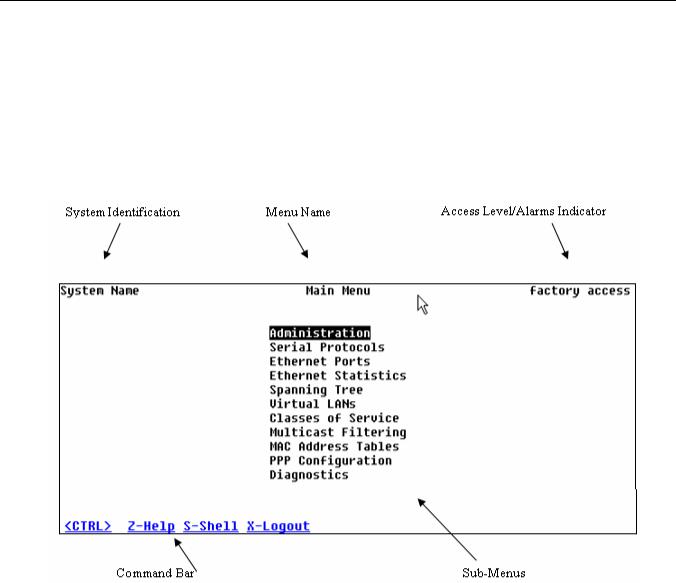
Figure 1: Main Menu With Screen Elements Identified........................................................................... |
16 |
Figure 2: Log in to The Device with a Web Browser.............................................................................. |
19 |
Figure 3: Log in to The Device with a Web Browser (secure login banner)........................................... |
20 |
Figure 4: Main Menu via Web Server Interface ...................................................................................... |
21 |
Figure 5: Parameters Form Example...................................................................................................... |
22 |
Figure 6: Administration Menu................................................................................................................ |
24 |
Figure 7: IP Interfaces Table .................................................................................................................. |
25 |
Figure 8: IP Interfaces Form ................................................................................................................... |
26 |
Figure 9: IP Gateways Form................................................................................................................... |
28 |
Figure 10: IP Services Form ................................................................................................................... |
29 |
Figure 11: System Identification Form .................................................................................................... |
31 |
Figure 12: Passwords Form.................................................................................................................... |
32 |
Figure 13: Time and Date Form.............................................................................................................. |
34 |
Figure 14: SNMP User Table.................................................................................................................. |
36 |
Figure 15: SNMP User Form .................................................................................................................. |
37 |
Figure 16: SNMP Security to Group Maps Table.................................................................................... |
38 |
Figure 17: SNMP Security to Group Maps Form .................................................................................... |
38 |
Figure 18: SNMP Access Table.............................................................................................................. |
39 |
Figure 19: SNMP Access Form .............................................................................................................. |
40 |
Figure 20: RADIUS Server summary...................................................................................................... |
44 |
Figure 21: RADIUS Server Form ............................................................................................................ |
44 |
Figure 22: TACACS+ Server summary................................................................................................... |
46 |
Figure 23: TACACS+ Server Form ......................................................................................................... |
47 |
Figure 24: DHCP Relay Agent Form....................................................................................................... |
48 |
Figure 25: Local Syslog Form................................................................................................................. |
49 |
Figure 26: Remote Syslog Client Form................................................................................................... |
50 |
Figure 27: Remote Syslog Server Table................................................................................................. |
50 |
Figure 28: Remote Syslog Server Form ................................................................................................. |
51 |
Figure 29: Using A Router As A Gateway............................................................................................... |
52 |
Figure 30: Character Encapsulation ....................................................................................................... |
55 |
Figure 31: RTU Polling ........................................................................................................................... |
55 |
Figure 32: Broadcast RTU Polling .......................................................................................................... |
56 |
Figure 33: Permanent and Dynamic Master Connection Support .......................................................... |
57 |
Figure 34: Modbus Client and Server ..................................................................................................... |
59 |
Figure 35: Sources of Delay and Error in an End-to-End Exchange ...................................................... |
60 |
Figure 36: Source/Destination Two Way Communication ...................................................................... |
62 |
Figure 37: Optical loop topology ............................................................................................................. |
66 |
Figure 38: Serial Protocols Menu............................................................................................................ |
67 |
Figure 39: Serial Ports Table .................................................................................................................. |
68 |
Figure 40: Serial Ports Form................................................................................................................... |
68 |
Figure 41: Raw Socket Table ................................................................................................................. |
70 |
Figure 42: Raw Socket Form .................................................................................................................. |
71 |
Figure 43: Preemptive Raw Socket Table .............................................................................................. |
73 |
Figure 44: Preemptive Raw Socket Form............................................................................................... |
73 |
Figure 45: Modbus Server Table ............................................................................................................ |
75 |
Figure 46: Modbus Server Form ............................................................................................................. |
75 |
Figure 47: Modbus Client Form .............................................................................................................. |
76 |
RS400 |
9 |
ROS™ v3.5 |

Table Of Figures
Figure 48: WIN and TIN Form................................................................................................................. |
77 |
Figure 49: MicroLok Form....................................................................................................................... |
79 |
Figure 50: DNP Form.............................................................................................................................. |
80 |
Figure 51: Mirrored Bits Table ................................................................................................................ |
81 |
Figure 52: Mirrored Bits Form................................................................................................................. |
82 |
Figure 53: Device Address Table............................................................................................................ |
83 |
Figure 54: Device Address Form ............................................................................................................ |
84 |
Figure 55: Dynamic Device Address Table............................................................................................. |
85 |
Figure 56: Dynamic Device Address Form ............................................................................................. |
85 |
Figure 57: Links Statistics Table............................................................................................................. |
86 |
Figure 58: Links Statistics Form.............................................................................................................. |
87 |
Figure 59: Connection Statistics Table ................................................................................................... |
88 |
Figure 60: Serial Port Statistics Table..................................................................................................... |
89 |
Figure 61: Clear Serial Port Statistics Form............................................................................................ |
90 |
Figure 62: Reset Serial Port(s) Form...................................................................................................... |
90 |
Figure 63: Controller Protection Through LFI ......................................................................................... |
93 |
Figure 64: Ethernet Ports Menu.............................................................................................................. |
95 |
Figure 65: Port Parameters Table........................................................................................................... |
96 |
Figure 66: Port Parameters Form ........................................................................................................... |
96 |
Figure 67: Port Rate Limiting Table ........................................................................................................ |
99 |
Figure 68: Port Rate Limiting Form......................................................................................................... |
99 |
Figure 69: Port Mirroring Form.............................................................................................................. |
101 |
Figure 70: Link Detection Form............................................................................................................. |
102 |
Figure 71: Accessing PoE Parameters................................................................................................. |
103 |
Figure 72: PoE Parameters Table ........................................................................................................ |
103 |
Figure 73: PoE Parameters Form......................................................................................................... |
104 |
Figure 74: Accessing EoVDSL Parameters .......................................................................................... |
106 |
Figure 75: EoVDSL Parameters Table ................................................................................................. |
106 |
Figure 76: EoVDSL Parameters Form.................................................................................................. |
107 |
Figure 77: Port Status Table................................................................................................................. |
108 |
Figure 78: Ethernet Port Statistics Menu .............................................................................................. |
111 |
Figure 79: Ethernet Statistics Table...................................................................................................... |
112 |
Figure 80: Ethernet Port Statistics Table .............................................................................................. |
114 |
Figure 81: Ethernet Port Statistics Form............................................................................................... |
115 |
Figure 82: Clear Ethernet Port Statistics Form ..................................................................................... |
119 |
Figure 83: RMON History Controls Table ............................................................................................. |
120 |
Figure 84: RMON History Controls Form.............................................................................................. |
121 |
Figure 85: RMON History Samples Table............................................................................................. |
122 |
Figure 86: RMON History Samples Form ............................................................................................. |
123 |
Figure 87: The Alarm Process .............................................................................................................. |
126 |
Figure 88: RMON Alarms Table............................................................................................................ |
126 |
Figure 89: RMON Alarms Form ............................................................................................................ |
127 |
Figure 90: RMON Events Table............................................................................................................ |
129 |
Figure 91: RMON Events Form ............................................................................................................ |
130 |
Figure 92: RMON Event Log Table....................................................................................................... |
131 |
Figure 93: RMON Event Log Form ....................................................................................................... |
132 |
Figure 94: Bridge and Port States ........................................................................................................ |
134 |
Figure 95: Bridge and Port Roles ......................................................................................................... |
135 |
Figure 96: Example of a Structured Wiring Configuration..................................................................... |
143 |
Figure 97: Example of a Ring Backbone Configuration........................................................................ |
144 |
Figure 98: Port Redundancy................................................................................................................. |
145 |
|
Table Of Figures |
Figure 99: Spanning Tree Menu ........................................................................................................... |
146 |
Figure 100: Bridge RSTP Parameters Form......................................................................................... |
147 |
Figure 101: Port RSTP Parameter Table.............................................................................................. |
150 |
Figure 102: Port RSTP Parameter Form .............................................................................................. |
150 |
Figure 103: MST Region Identifier Table.............................................................................................. |
153 |
Figure 104: Bridge MSTI Parameters ................................................................................................... |
154 |
Figure 105: Port MSTI Parameter Table............................................................................................... |
155 |
Figure 106: Port MSTI Parameter Form ............................................................................................... |
155 |
Figure 107: Bridge RSTP Statistics Form............................................................................................. |
157 |
Figure 108: Port RSTP Statistics Table ................................................................................................ |
159 |
Figure 109: Bridge RSTP Parameters Form......................................................................................... |
160 |
Figure 110: Bridge MSTI Statistics Table ............................................................................................. |
162 |
Figure 111: Port MSTI Statistics Table ................................................................................................. |
163 |
Figure 112: Port MSTI Statistics Form.................................................................................................. |
164 |
Figure 113: Using GVRP ...................................................................................................................... |
173 |
Figure 114: Using QinQ Example ......................................................................................................... |
174 |
Figure 115: Multiple overlapping VLANs............................................................................................... |
175 |
Figure 116: Inter-VLAN Communications ............................................................................................. |
176 |
Figure 117: Virtual LANs Menu............................................................................................................. |
177 |
Figure 118: Global VLAN Parameters Form ......................................................................................... |
177 |
Figure 119: Static VLANs Table............................................................................................................ |
178 |
Figure 120: Static VLANs Form ............................................................................................................ |
178 |
Figure 121: Port VLAN Parameters Table ............................................................................................ |
180 |
Figure 122: Port VLAN Parameters Form............................................................................................. |
180 |
Figure 123: VLAN Summary Table....................................................................................................... |
182 |
Figure 124: Determining The CoS Of A Received Frame..................................................................... |
186 |
Figure 125: Classes Of Service Menu .................................................................................................. |
187 |
Figure 126: Global CoS Parameters Form ........................................................................................... |
187 |
Figure 127: Port CoS Parameter Table ................................................................................................ |
188 |
Figure 128: Port CoS Parameter Form................................................................................................. |
189 |
Figure 129: Priority to CoS Mapping Table........................................................................................... |
189 |
Figure 130: Priority to CoS Mapping Form ........................................................................................... |
190 |
Figure 131: TOS DSCP to CoS Mapping Table.................................................................................... |
191 |
Figure 132: TOS DSCP to CoS Mapping Form .................................................................................... |
191 |
Figure 133: CoS Access Priorities Table .............................................................................................. |
192 |
Figure 134: CoS Access Priorities Form............................................................................................... |
193 |
Figure 135: IGMP Operation Example 1............................................................................................... |
196 |
Figure 136: IGMP Operation Example 2............................................................................................... |
198 |
Figure 137: Multicast Filtering Menu..................................................................................................... |
200 |
Figure 138: IGMP Parameters Form..................................................................................................... |
200 |
Figure 139: Static Multicast Groups Table............................................................................................ |
202 |
Figure 140: Static Multicast Group Form .............................................................................................. |
202 |
Figure 141: IP Multicast Groups Table ................................................................................................. |
203 |
Figure 142: MAC Address Tables Menu............................................................................................... |
207 |
Figure 143: Address Table.................................................................................................................... |
208 |
Figure 144: MAC Address Learning Options Form............................................................................... |
209 |
Figure 145: Static MAC Address Table................................................................................................. |
210 |
Figure 146: Static MAC Address Form ................................................................................................. |
210 |
Figure 147: Network Discovery Menu................................................................................................... |
214 |
Figure 148: Global LLDP Parameters Form ......................................................................................... |
215 |
Figure 149: Port LLDP Parameters Table............................................................................................. |
216 |
RS400 |
11 |
ROS™ v3.5 |

Table Of Figures
Figure 150: Port LLDP Parameters Form ............................................................................................. |
216 |
Figure 151: LLDP Global Remote Statistics Form ................................................................................ |
217 |
Figure 152: LLDP Neighbor Information Table ..................................................................................... |
218 |
Figure 153: LLDP Statistics Table ........................................................................................................ |
219 |
Figure 154: Remote Dial-in For Monitoring........................................................................................... |
221 |
Figure 155: Router Concentration......................................................................................................... |
222 |
Figure 156: PPP Configuration Menu ................................................................................................... |
225 |
Figure 157: PPP Modem Settings Form ............................................................................................... |
226 |
Figure 158: PPP Control Form.............................................................................................................. |
227 |
Figure 159: PPP Users Table ............................................................................................................... |
229 |
Figure 160: PPP Users Form................................................................................................................ |
229 |
Figure 161: PPP Statistics Form........................................................................................................... |
231 |
Figure 162: Clear PPP Statistics Form ................................................................................................. |
233 |
Figure 163: Reset PPP Port Form ........................................................................................................ |
233 |
Figure 164: Gateway Collisions ............................................................................................................ |
235 |
Figure 165: Diagnostics Menu .............................................................................................................. |
237 |
Figure 166: Alarm Table ....................................................................................................................... |
238 |
Figure 167: CPU Diagnostics Form ...................................................................................................... |
239 |
Figure 168: Viewing the System Log .................................................................................................... |
241 |
Figure 169: Product Information Form.................................................................................................. |
242 |
Figure 170: Load Factory Defaults Dialog ............................................................................................ |
243 |
Figure 171: Reset Device Dialog .......................................................................................................... |
244 |
Figure 172: Displaying the list of available commands ......................................................................... |
245 |
Figure 173: Displaying help for a command ......................................................................................... |
246 |
Figure 174: Displaying Directory of a RuggedCom Device................................................................... |
246 |
Figure 175: Displaying Trace settings................................................................................................... |
248 |
Figure 176: Enabling Trace................................................................................................................... |
248 |
Figure 177: Starting Trace .................................................................................................................... |
249 |
Figure 178 Example of an Upgrade using XModem ............................................................................. |
251 |
Figure 179 Example of an Upgrade using a TFTP client on your workstation...................................... |
252 |
Figure 180 Example of an Upgrade using ROS™ TFTP Client............................................................. |
253 |
Figure 181 The SQL command and SQL help...................................................................................... |
255 |
Figure 182 Brief snippet of SQL command for finding the correct table name ..................................... |
256 |
Figure 183 Selecting a table ................................................................................................................. |
256 |
Figure 184 Select a parameter within a table ....................................................................................... |
256 |
Figure 185 Selecting rows in a table based upon parameter values .................................................... |
257 |
Figure 186 Selecting rows in a table based upon multiple parameter values....................................... |
257 |
Figure 187 Changing Values In A Table............................................................................................... |
257 |
Figure 188 Setting default values into a table....................................................................................... |
257 |
Figure 189 Using RSH and SQL........................................................................................................... |
258 |

Preface
Preface
This manual contains instructions, examples, guidelines, and general theory on how to use the Rugged Operating System (ROS™) management software.
Supported Platforms
ROS™ has been designed to work on many RuggedCom product hardware platforms. This ensures consistency of the user experience when migrating from one product model to another. In fact, a single ‘binary’ image supports all RuggedCom ROS™ based products that includes:
•RuggedSwitch™ i800, i801, i802, and i803
•RuggedSwitch™ RS8000 and RS1600
•RuggedSwitch™ RS900/RS930 with both ‘L’ (EoVDSL) and ‘W’ (WLAN) port variants
•RuggedSwitch™ RS900G/RS940G with Gigabit
•RuggedSwitch™ RS969/M969 waterproof with Gigabit
•RuggedSwitch™ RSG2100/M2100 and RSG2200/M2200 modular switches with Gigabit
•RuggedServer™ RS416, RS910 and RS920 modular servers
•RuggedServer™ RS400
•RuggedServer™ RMC30
Each product model has a subset of the entire ROS™ feature set. This manual is intended for use with the RS400 product model(s) and has been streamlined to only describe the relevant features.
Who Should Use This User Guide
This guide is to be used by network technical support personnel who are familiar with the operation of networks. Others who might find the book useful are network and system planners, system programmers and line technicians.
How Chapters are organized
The index of this guide has been prepared with:
•Entries to each of the “Features” sections of the manual
•Entries to each of the “Troubleshooting” sections of the manual (located at the end of each chapter)
•Entries to each of the Menus, organized by name
Document Conventions
This publication uses the following conventions:
Note: Means reader take note. Notes contain helpful suggestions or references to materials not contained in this guide.
It is recommended that you use this guide along with the following applicable documents:
RS400 |
13 |
ROS™ v3.5 |

Preface
•RS400 Installation Guide
•RuggedCom Fiber Guide
•RuggedCom Wireless Guide
•White paper: Rapid Spanning Tree in Industrial Networks
Applicable Firmware Revision
This guide is applicable to ROS™ software revision v3.5.x.
Firmware/User Guide Version Numbering System
ROS has a three-digit version numbering system of the form X.Y.Z where each digit is a number starting from zero. The 'X.Y' digits represent the functional version of ROS whereas the 'Z' digit represents firmware patches. The 'X' digit is incremented for major functional updates of the product. The 'Y' digit is incremented for minor functional updates of the product. The 'Z' digit is incremented for bug fixes, cosmetic enhancements and other minor issues.
User guides follow the same format. In general, a user guide will have the same 'X.Y' digits as the firmware to which it corresponds.
It is RuggedCom's policy to provide Web access to only the latest 'patch' release for a version of firmware. If you decide that an upgrade is merited, then getting all the fixes only makes sense. It is for this reason that release notes are created detailing all patches for a given functional version.
ROS™ v3.5 |
14 |
RS400 |

Administration
1 Administration
The Administration menu covers the configuration of administrative parameters of both device and network (local services availability, security methods employed, system identification and functionality related to the IP network):
•IP Address, Subnet Mask and Gateway Address (static or dynamically obtainable)
•Management VLAN
•Management Connection Inactivity Timeout
•TFTP Server Permissions
•System Identification
•Passwords
•Time and Date
•SNTP to keep the time and date synchronized
•SNMP Management
•Radius Server
•DHCP Relay Agent
•Remote Syslog
1.1The ROS™ User Interface
1.1.1 Using the RS232 Port to Access the User Interface
Attach a terminal (or PC running terminal emulation software) to the RS232 port. The terminal should be configured for 8 bits, no parity operation at 57.6 Kbps. Hardware and software flow control must be disabled. Select a terminal type of VT100.
Once the terminal is connected, pressing any key on the keyboard will prompt for the username and password to be entered.
The switch is shipped with a default administrator username “admin” and password “admin”. Once successfully logged in, the user will be presented with the main menu.
RS400 |
15 |
ROS™ v3.5 |
Administration
1.1.2 The Structure of the User Interface
The user interface is organized as a series of menus with an escape to a command line interface (CLI) shell. Each menu screen presents the switch name (as proved by the System Identification parameter), Menu Title, Access Level, Alarms indicator, Sub-Menus and Command Bar.
Sub-menus are entered by selecting the desired menu with the arrow keys and pressing the enter key. Pressing the escape key ascends to the parent menu.
Figure 1: Main Menu With Screen Elements Identified
The command bar offers a list of commands that apply to the currently displayed menu. These commands include:
•<CTRL> Z to display help on the current command or data item
•<CTRL> S to switch to the CLI shell
•<CTRL> U/D to jump to next/previous page of a status display
The main menu also provides a <CTRL> X command, which will terminate the session. This type of menu is accessible via serial consol, telnet session and SSH session.
1.1.3 Making Configuration Changes
When changing a data item the user selects the data item by the cursor keys and then pressing the enter key. The cursor will change position to allow editing of the data item.
ROS™ v3.5 |
16 |
RS400 |

Administration
Typing a new value after pressing enter always erases the old parameter value. The left and right cursor keys can be used to position the edit point without erasing the old parameter value. The up and down cursor keys can be used to cycle through the next higher and lower values for the parameter.
After the parameter has been edited, press enter again to change other parameters. When all desired parameters have been modified, press <CTRL> A to apply changes. The switch will automatically prompt you to save changes when you leave a menu in which changes have been made.
Some menus will require you to press <CTRL> I to insert a new record of information and <CTRL> L to delete a record.
1.1.4 Updates Occur In Real Time
All configuration and display menus present the values at the current instant, automatically updating if changed from other user interface sessions or SNMP. All statistics menus will display changes to statistics as they occur.
1.1.5 Alarm Indications Are Provided
Alarms are events for which the user is notified through the Diagnostics submenu. All configuration and display menus present an indication of the number of alarms (in the upper right hand corner of the screen) as they occur, automatically updating as alarms are posted and cleared.
1.1.6 The CLI Shell
The user interface provides a shell for operations that are more easily performed at the command line. You may switch back and forth from the menu system and shell by pressing <CTRL> S. For more information on the capabilities of the shell see the approapriate chapter of this guide.
1.2 The ROS™ Secure Shell Server
1.2.1 Using a Secure Shell to Access the User Interface
SSH (Secure Shell) is a network protocol which provides a replacement for insecure remote login and command execution facilities, such as telnet and remote shell. SSH encrypts traffic in both directions, preventing traffic sniffing and password theft.
SSH protocol version 2 is implemented in ROS. The authentication method is keyboard interactive password authentication. User name will not be verified in order to grant access to SSH server. The passwords to be used for login are configured in Password Table and user’s privileges are the same as for user logged in via the console port.
1.2.2 Using a Secure Shell to Transfer Files
ROS implements SFTP protocol over SSH to transfer files in secure manner. The file system is created in one directory only. Also, all the files are created in the system at startup time and can not be deleted, created, renamed. Files can be downloaded (upgraded) and uploaded (to be analyzed outside of the unit).
The implemented commands are: dir – a file directory
RS400 |
17 |
ROS™ v3.5 |

Administration
get – upload from the switch and download to PC put – upload from PC and download to PC
1.3 The ROS™ Web Server Interface
1.3.1 Using a Web Browser to Access the Web Interface
A web browser uses a secure communications method called Secure Socket Layer (SSL) to encrypt traffic exchanged with its clients. Web server guarantees that communications with the client is kept private. If client requires access via unsecure http port, it will be rerouted to the secure port. The access via SSL will be granted any client that provides the correct password.
Your browser may complain about SSL Certificate that Web server issues. It happens because the certificate that comes with the Web server is not issued by a recognized certificate authority. However, network traffic is still encrypted.
Start a web browser session and open a connection to the switch by entering a URL that specifies its hostname or IP address (e.g. http://179.1.0.45). Once the switch is contacted, start the login process by clicking on the “Login” link. The resulting page should be similar to that presented below:
ROS™ v3.5 |
18 |
RS400 |
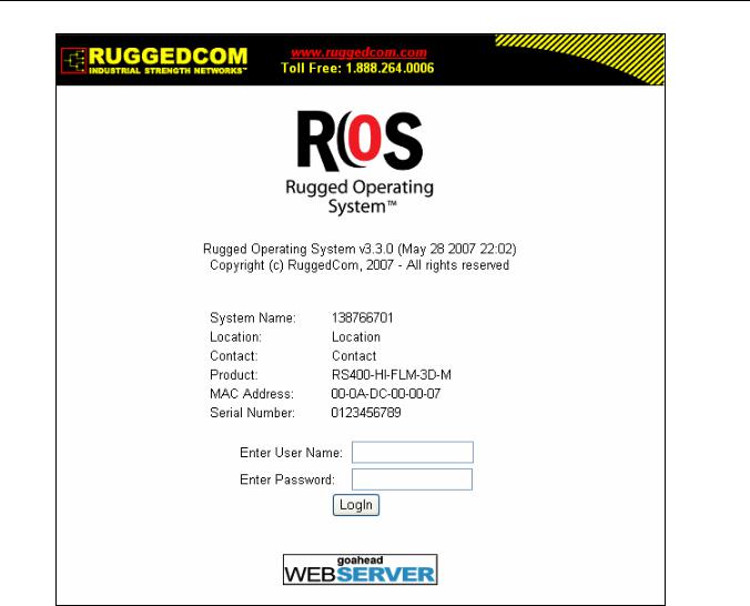
Administration
Figure 2: Log in to The Device with a Web Browser
Enter the “admin” user name and the appropriate password for the admin user, and then click on the “LogIn” button. The switch is shipped with a default administrator password of “admin”. Once successfully logged in, the user will be presented with the main menu.
If the user wants to hide device information from the login screen, the ‘Login Banner’ option in the System Identification menu must be set to ‘secure’.
RS400 |
19 |
ROS™ v3.5 |
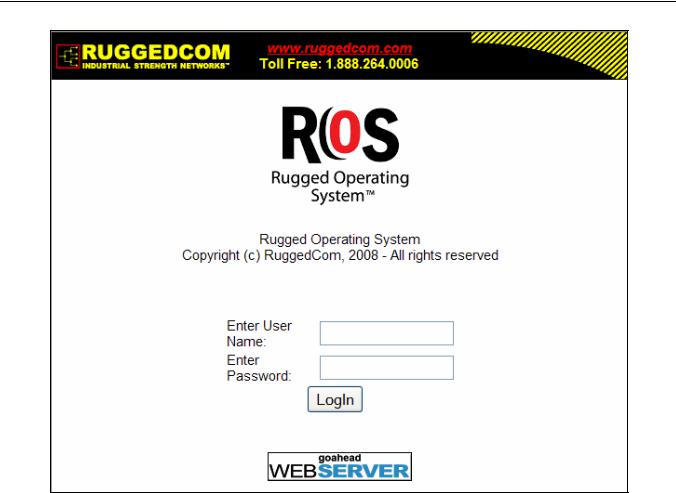
Administration
Figure 3: Log in to The Device with a Web Browser (secure login banner)
ROS™ v3.5 |
20 |
RS400 |
Administration
1.3.2 The Structure of the Web Interface
The user interface is organized as a series of linked web pages. The main menu provides the links and allows them to be expanded to display lower level pages for a particular configuration system.
Figure 4: Main Menu via Web Server Interface
Each web page presents the switch name (as proved by the System Identification parameter), Menu Title link and user’s access name or Alarms link if any alarms are reported.
The Menu title link takes you to a page that provides help for the configuration parameters provided by that page.
Alarms are events for which the user is notified by following the Alarms link (these alarms may also be viewed and cleared through the Diagnostics submenu). All configuration and display menus present an indication of the number of alarms (in the upper right hand corner of the screen) as they occur, automatically updating as alarms are posted and cleared.
1.3.3 Making Configuration Changes
When changing a data item the user selects the data item by selecting the field to edit with the mouse, entering a new value and clicking on the apply field. More than one parameter may be modified at a time.
RS400 |
21 |
ROS™ v3.5 |
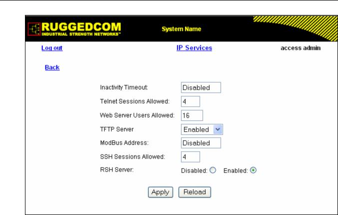
Administration
Figure 5: Parameters Form Example
Some menus will require you to create or delete new records of information.
1.3.4 Updating Statistics Displays
You may click the refresh button to update statistics displays.
ROS™ v3.5 |
22 |
RS400 |

Administration
1.4 Administration Menu
The Administration menu provides ability to configure network and switch administration parameters.
RS400 |
23 |
ROS™ v3.5 |

Administration
Figure 6: Administration Menu
ROS™ v3.5 |
24 |
RS400 |
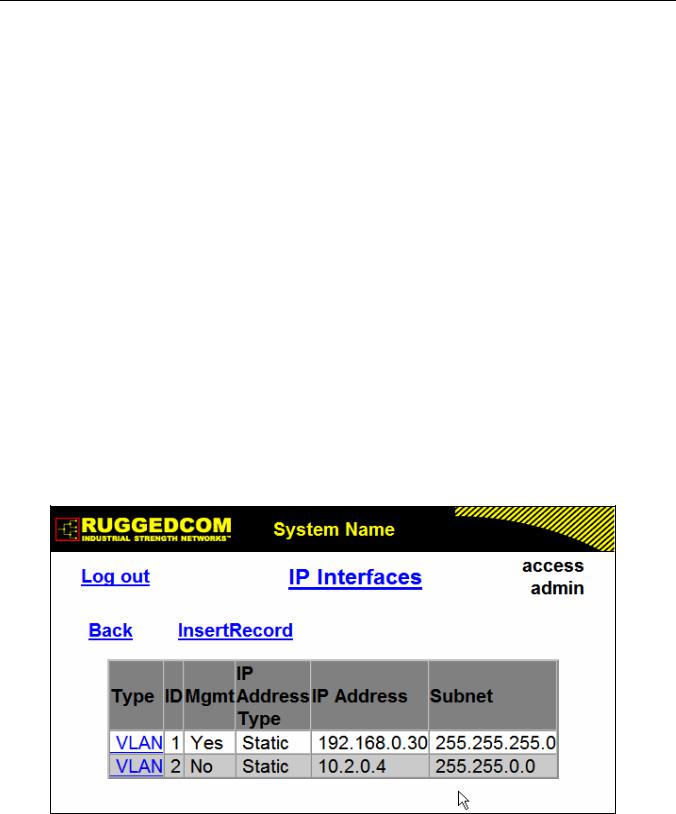
Administration
1.5 IP Interfaces
These parameters provide the ability to configure IP connection parameters such as address, network, and mask.
The user can configure an IP Interface for each subnet (VLAN). One of the interfaces is configured as management interface. IP services: TFTP server, SNMP server, Telnet server, SSH server, RSH server, Web server, authentication using RADIUS server, DHCP client, BOOTP client, DHCP relay agent will be available only via management interface. Different IP interfaces MUST NOT overlap, e.g. the subnet mask must be unique.
15 IP interfaces can be configured in the device. In VLAN unaware mode, and in devices that do not act as switches (as RMC30), only one IP interface can be configured.
On non-management interfaces, only static IP addresses can be assigned.
On management interface, the user can choose from the following IP Address type: Static, DHCP, BOOTP and Dynamic. Static IP Address type refers to the manual assignment of IP address while DHCP, BOOTP and Dynamic IP Address types refer to the automatic assignment of IP address.
DHCP is widely used in LAN environments to dynamically assign IP addresses from a centralized server, which reduces the overhead of administrating IP addresses.
BOOTP is a subset of the DHCP protocol. ROSTM supports transfer of a BOOTFILE via BOOTP. The BOOTFILE represents any valid ROSTM file such as config.csv. The name of BOOTFILE on the BOOTP server must match the corresponding ROSTM file.
The Dynamic IP Address type refers to a combination of the BOOTP and DHCP protocols. Starting with BOOTP, the system will try BOOTP and DHCP in a round-robin fashion until it will get a response from the corresponding server.
Figure 7: IP Interfaces Table
RS400 |
25 |
ROS™ v3.5 |
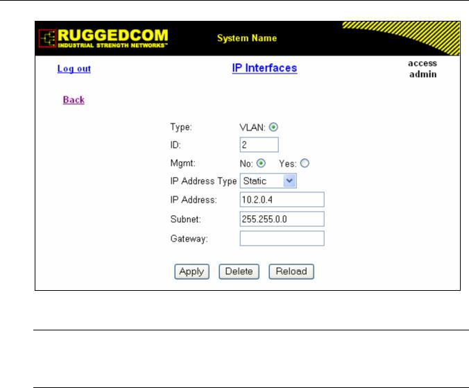
Administration
Figure 8: IP Interfaces Form
Note: The IP address and mask configured for management VLAN are not changed when resetting all configuration parameters to defaults and will be assigned to default VLAN ID of 1. Changes to the IP address take effect immediately. All IP connections in place at the time of an address change will be lost.
Type
Synopsis: { VLAN } Default: VLAN
Specifies the type of the interface for which this IP interface is created.
ID
Synopsis: 1 to 4094 Default: 1
Specifies the ID of the interface for which this IP interface is created. If interface type is VLAN, represents VLAN ID.
Mgmt
Synopsis: { No, Yes } Default: No
Specifies whether the IP interface is the device management interface.
IP Address Type
Synopsis: { Static, Dynamic, DHCP, BOOTP } Default: Static
Specifies whether the IP address is static or dynamically assigned via DHCP or BOOTP. Option
ROS™ v3.5 |
26 |
RS400 |

Administration
DYNAMIC is a common case of dynamically assigned IP address. It switches between BOOTP and DHCP until it gets the response from the relevant server. Must be static for non management interfaces
IP Address
Synopsis: ###.###.###.### where ### ranges from 0 to 255 Default: 192.168.0.1
Specifies the IP address of this device. An IP address is a 32-bit number that is notated by using four numbers from 0 through 255, separated by periods. Only a unicast IP address is allowed which ranges from 1.0.0.0 to 233.255.255.255
Subnet
Synopsis: ###.###.###.### where ### ranges from 0 to 255 Default: 255.255.255.0
Specifies the IP subnet mask of this device. An IP subnet mask is a 32-bit number that is notated by using four numbers from 0 through 255, separated by periods. Typically, subnet mask numbers use either 0 or 255 as values (e.g. 255.255.255.0) but other numbers can appear.
RS400 |
27 |
ROS™ v3.5 |
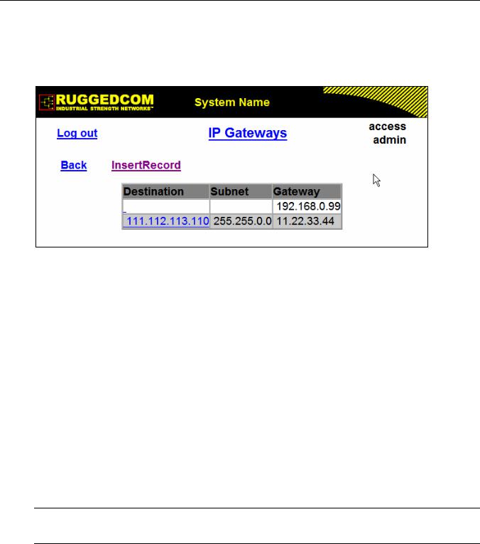
Administration
1.6 IP Gateways
These parameters provide the ability to configure gateways. A maximum of 10 gateways can be configured. When both the Destination and Subnet fields are both 0.0.0.0 (displayed as blank space), the gateway is a default gateway.
Figure 9: IP Gateways Form
Destination
Synopsis: ###.###.###.### where ### ranges from 0 to 255 Default: 0.0.0.0
Specifies the IP address of the destination device. An IP address is a 32-bit number that is notated by using four numbers from 0 through 255, separated by periods.
Subnet
Synopsis: ###.###.###.### where ### ranges from 0 to 255 Default: 0.0.0.0
Specifies the IP subnet mask of the destination. An IP subnet mask is a 32-bit number that is notated by using four numbers from 0 through 255, separated by periods. Typically, subnet mask numbers use either 0 or 255 as values (e.g. 255.255.255.0) but other numbers can appear.
Gateway
Synopsis: ###.###.###.### where ### ranges from 0 to 255 Default: 0.0.0.0
Specifies the gateway IP address. The gateway address must be on the same IP subnet as this device.
Note: The default gateway configuration will not be changed when resetting all configuration parameters to defaults.
ROS™ v3.5 |
28 |
RS400 |
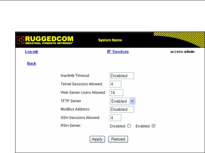
Administration
1.7 IP Services
These parameters provide the ability to configure properties for IP services provided by the device.
Figure 10: IP Services Form
Inactivity Timeout
Synopsis: 1 to 60 or { Disabled } Default: 5 min
Specifies when the console will timeout and display the login screen if there is no user activity. A value of zero disables timeouts for console and Telnet users. For Web Server users maximum timeout value is limited to 30 minutes.
Telnet Sessions Allowed
Synopsis: 0 to 4 Default: 4
Limits the number of Telnet sessions. A value of zero prevents any Telnet access.
Web Server Users Allowed
Synopsis: 1 to 16 Default: 16
Limits the number of simultaneous web server users.
TFTP Server
Synopsis: { Disabled, Get Only, Enabled } Default: Get Only
As TFTP is a very insecure protocol, this parameter allows the user to limit or disable TFTP
RS400 |
29 |
ROS™ v3.5 |

Administration
Server access.
DISABLED |
- |
disables read and write access to TFTP Server |
GET ONLY |
- |
only allows to read files via TFTP Server |
ENABLED |
- |
allows to read and write files via TFTP Server |
ModBus Address
Synopsis: 1 to 254 or { Disabled } Default: Disabled
Determines the Modbus address to be used for Management through Modbus.
SSH Sessions Allowed
Synopsis: 1 to 4 Default: 4
Limits the number of SSH sessions.
RSH Server
Synopsis: { Disabled, Enabled } Default: Enabled
Disables/enables Remote Shell access.
ROS™ v3.5 |
30 |
RS400 |
 Loading...