

Page 1
Owner’s Manual
Manuel d’utilisation
Bedienungsanleitung
Manuale di istruzioni
Manual de instrucciones
Gebruiksaanwijzing
RB-951MkII
Stereo Power Amplifier
Amplificateur de Puissance Stéréo
Stereo-Endstufe
Finale di Potenza Stereo
Etapa de Potencia Estereofónica
Stereo Eindversterker
POWER AMPLIFIER RB-951 MkII
POWER
BRIDGED
MONO
CH1
CH2
PROTECTION
CLIPPING
LEVEL
LEVEL
Page 2
RB-951MkII
2
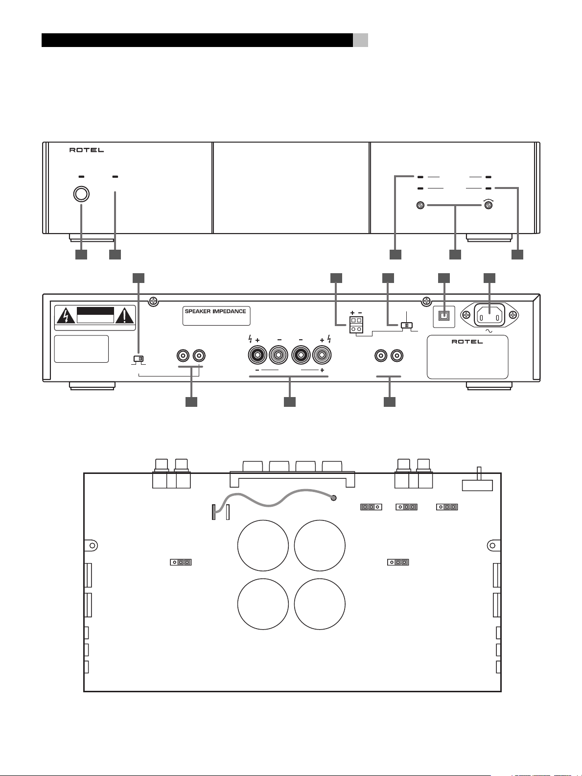
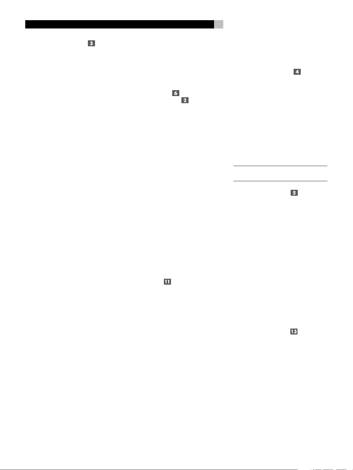
1: Controls, Connections, & Internal Jumpers • Commandes, prises et cavaliers internes
Bedienelemente, Anschlüsse und interne Jumper • Controlli, collegamenti e ponticelli interni
Controles, Conexiones y Puentes Internos
De bedieningsorganen, aansluitingen en interne doorverbindingen
POWER AMPLIFIER RB-951 MkII
English
POWER
AVIS:
RISQUE DE CHOC ELECTRIQUE–NE PAS OUVRIR
WARNING:
TO REDUCE THE RISK
OF FIRE OR ELECTRICAL
SHOCK, DO NOT EXPOSE
THIS EQUIPMENT TO RAIN
OR MOISTURE.
BRIDGED
CAUTION
RISK OF ELECTRIC SHOCK
DO NOT OPEN
MONO
BRIDGED
MONO
NORMAL
STEREO
STEREO: 4 OHMS MINIMUM
BRIDGED: 8 OHMS MINIMUM
INPUT
CH2 CH1
SPEAKERS
CHANNEL 2 CHANNEL 1
BRIDGED
12
7
12 TRIG IN
3 4
8 9 106
SIGNAL SENSE
CH2 CH1
SIGNAL OUTPUT
LINK
1311
CH1
LEVEL
10 A
OFF AC BREAKER
POWER CONSUMPTION: 200W
PROTECTION
CLIPPING
POWER AMPLIFIER
MODEL NO. RB-951 MkII
RB-951
CH2
LEVEL
51 2
MkII
P2
123
S605
123
P1P3
S603
123
S602
123
S606
123
S604
Default Jumper settings shown in illustration • Les réglages par défaut des cavaliers sont représentés sur l'illustration
In dieser Abbildung sind die Standardpositionen der Jumper dargestellt • Nell'illustrazione sono mostrate le posizioni di default dei cavallotti
En el dibujo se muestran las ubicaciones de los puentes por defecto • Afbeelding standaard jumperinstellingen
Page 3
3
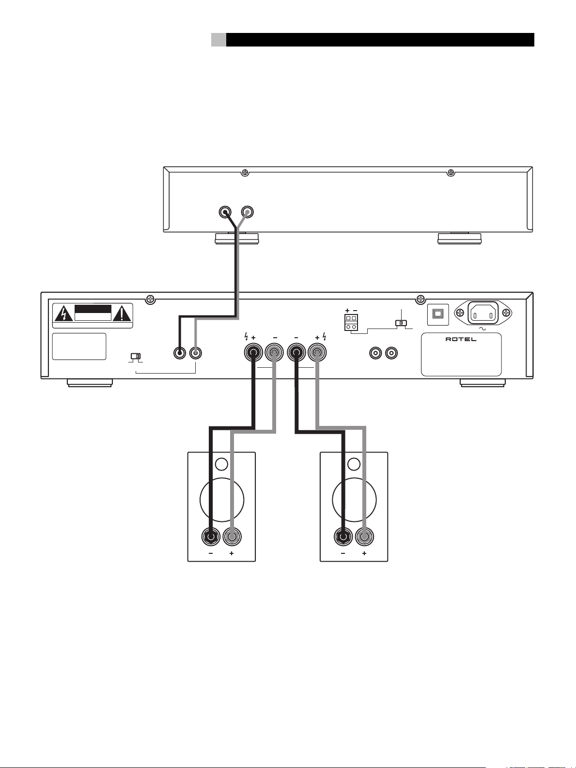
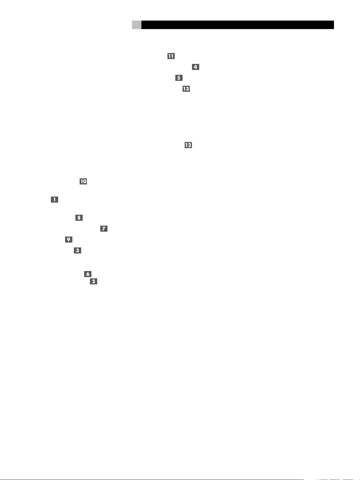
2: Hookup (Stereo or Parallel Mono modes) • Branchements (modes Stéréo et Mono Parallèle)
Anschlußdiagramm für Stereobetrieb oder Parallel-Mono-Modus
Collegamenti (configurazione Stereo o Mono Parallelo)
Conexión (Modo Estereofónico o Monofónico Paralelo)
De ingangsaansluitingen en luidsprekerverbindingen (in stereo of parallel mono)
PREAMPLIFIER • PRÉAMPLIFICATEUR • VORVERSTÄRKER • PREAMPLIFICATORE • PREAMPLIFICADOR • VOORVERSTERKER
RCA OUTPUTS
L
R
CAUTION
RISK OF ELECTRIC SHOCK
DO NOT OPEN
AVIS:
RISQUE DE CHOC ELECTRIQUE–NE PAS OUVRIR
WARNING:
TO REDUCE THE RISK
OF FIRE OR ELECTRICAL
SHOCK, DO NOT EXPOSE
THIS EQUIPMENT TO RAIN
OR MOISTURE.
BRIDGED
MONO
NORMAL
STERO
INPUT
CH2 CH1
SPEAKERS
CHANNEL 2 CHANNEL 1
BRIDGED
12 TRIG IN
SIGNAL SENSE
CH2 CH1
SIGNAL OUTPUT
LINK
10 A
OFF AC BREAKER
POWER AMPLIFIER
MODEL NO. RB-951 MkII
POWER CONSUMPTION: 200W
RB-951
MkII
Page 4
RB-951MkII
4
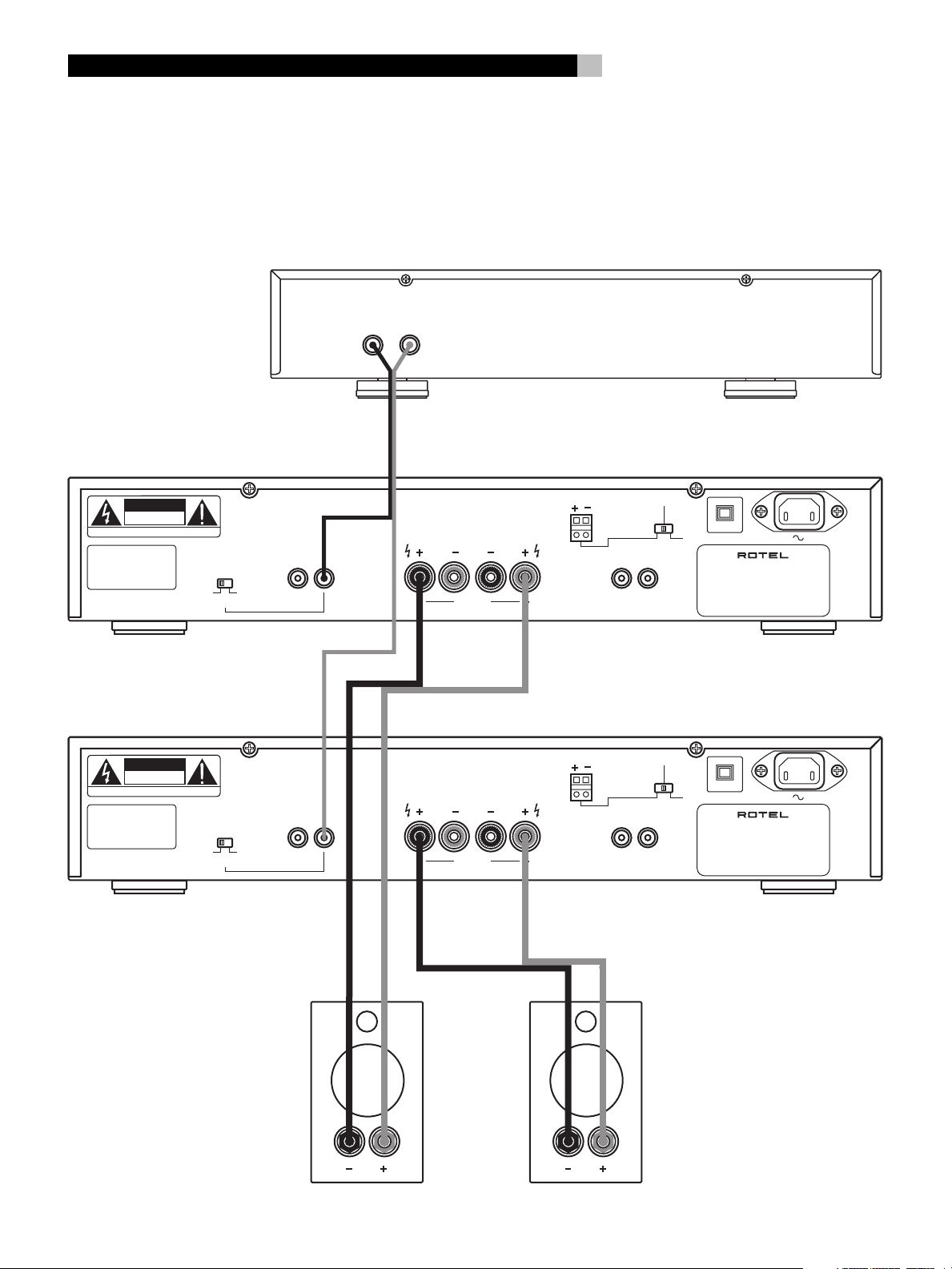
3: Hookup (Bridged Mono mode) • Branchement (mode Mono Ponté)
Anschlußdiagramm bei Brückenschaltung • Collegamenti (Mono configurazione a ponte)
Conexión (Modo Monofónico Puenteado)
De ingangsaansluitingen en luidsprekerverbindingen (in gebrugde situatie)
PREAMPLIFIER • PRÉAMPLIFICATEUR • VORVERSTÄRKER • PREAMPLIFICATORE • PREAMPLIFICADOR • VOORVERSTERKER
RCA OUTPUTS
L
R
CAUTION
RISK OF ELECTRIC SHOCK
DO NOT OPEN
AVIS: RISQUE DE CHOC ELECTRIQUE–NE PAS OUVRIR
WARNING:
TO REDUCE THE RISK
OF FIRE OR ELECTRICAL
SHOCK, DO NOT EXPOSE
THIS EQUIPMENT TO RAIN
OR MOISTURE.
CAUTION
RISK OF ELECTRIC SHOCK
DO NOT OPEN
AVIS: RISQUE DE CHOC ELECTRIQUE–NE PAS OUVRIR
WARNING:
TO REDUCE THE RISK
OF FIRE OR ELECTRICAL
SHOCK, DO NOT EXPOSE
THIS EQUIPMENT TO RAIN
OR MOISTURE.
BRIDGED
MONO
BRIDGED
MONO
NORMAL
STERO
NORMAL
STERO
INPUT
CH2 CH1
INPUT
CH2 CH1
SPEAKERS
CHANNEL 2 CHANNEL 1
BRIDGED
SPEAKERS
CHANNEL 2 CHANNEL 1
BRIDGED
12 TRIG IN
12 TRIG IN
SIGNAL SENSE
CH2 CH1
SIGNAL OUTPUT
LINK
SIGNAL SENSE
CH2 CH1
SIGNAL OUTPUT
LINK
10 A
OFF AC BREAKER
POWER AMPLIFIER
MODEL NO. RB-951 MkII
POWER CONSUMPTION: 200W
RB-951
10 A
OFF AC BREAKER
POWER AMPLIFIER
MODEL NO. RB-951 MkII
POWER CONSUMPTION: 200W
RB-951
MkII
MkII
Page 5
5
English 8
Français 13
Deutsch 19
Italiano 25
Español 31
Nederlands 38
English
WARNING: There are no user serviceable parts inside.
Refer all servicing to qualified service personnel.
WARNING: To reduce the risk of fire or electric shock,
do not expose the unit to moisture or water. Do not
allow foreign objects to get into the enclosure. If the
unit is exposed to moisture, or a foreign object gets
into the enclosure, immediately disconnect the power
cord from the wall. Take the unit to a qualified service
person for inspection and necessary repairs.
Read all the instructions before connecting or operating the component. Keep this manual so you can refer to these safety instructions.
Heed all warnings and safety information in these instructions
and on the product itself. Follow all operating instructions.
Clean the enclosure only with a dry cloth or a vacuum cleaner.
You must allow 10 cm or 4 inches of unobstructed clearance around
the unit. Do not place the unit on a bed, sofa, rug, or similar surface
that could block the ventilation openings. If the unit is placed in
a bookcase or cabinet, there must be ventilation of the cabinet
to allow proper cooling.
Keep the component away from radiators, heat registers, stoves,
or any other appliance that produces heat.
The unit must be connected to a power supply only of the type
and voltage specified on the rear panel of the unit. (USA: 115 V/
60Hz, EC: 230V/50Hz)
Connect the component to the power outlet only with the supplied power supply cable or an exact equivalent. Do not modify
the supplied cable in any way. Do not attempt to defeat grounding and/or polarization provisions. The cable should be connected
to a 2-pin polarized wall outlet, matching the wide blade of the
plug to the wide slot of the receptacle. Do not use extension cords.
Do not route the power cord where it will be crushed, pinched,
bent at severe angles, exposed to heat, or damaged in any way.
Pay particular attention to the power cord at the plug and where
it exits the back of the unit.
The power cord should be unplugged from the wall outlet if the
unit is to be left unused for a long period of time.
Immediately stop using the component and have it inspected and/
or serviced by a qualified service agency if:
• The power supply cord or plug has been damaged.
• Objects have fallen or liquid has been spilled into the unit.
• The unit has been exposed to rain.
• The unit shows signs of improper operation
• The unit has been dropped or damaged in any way
Place the unit on a fixed, level surface strong enough to support
its weight. Do not place it on a moveable cart that could tip over.
Français
CONSEILS DE SÉCURITÉ
Explication des symboles graphiques
L’éclair dans un triangle équilatéral indique la présence interne
de tensions électriques élevées susceptibles de présenter des risques
graves d’électrocution.
ATTENTION:
Pour réduire le risque d’électrocution, ne pas retirer le
capot. Il n’y a à l’intérieur aucune pièce susceptible d’être
modifiée par l’utilisateur. En cas de problème, adressezvous à un réparateur agréé.
Le point d’exclamation dans un triangle équilatéral indique à
l’utilisateur la présence de conseils et d’informations importantes
dans le manuel d’utilisation accompagnant l’appareil. Leur lecture est impérative.
ATTENTION:
Il n’y a à l’intérieur aucune pièce susceptible d’être
modifiée par l’utilisateur. Adressez-vous impérativement
à une personne qualifiée.
ATTENTION:
Prenez garde à ce qu’aucun objet ou liquide ne tombe à
l’intérieur de l’appareil par ses orifices de ventilation;
Si l’appareil est exposé à l’humidité ou si un objet tombe
à l’intérieur, couper immédiatement l’alimentation secteur
de tous les appareils. Débrancher l’appareil des autres
maillons, et adressez-vous immédiatement et uniquement
à une personne qualifiée et agréée.
Lisez les instructions: Tous les conseils de sécurité et d’installation
doivent être lus avant de faire fonctionner l’appareil. Conservez
soigneusement ce livret - Vous devez pouvoir le consulter à nouveau
pour de futures références.
Respectez tous les conseils:Tous les conseils de sécurité doivent
être soigneusement respectés. Suivez les instructions - Respectez
les procédures d’installation et de fonctionnement indiquées dans
ce manuel.
Entretien: L’appareil doit être nettoyé uniquement avec un chiffon sec ou un aspirateur.
Ventilation: L’appareil doit être placé de telle manière que sa propre
ventilation puisse fonctionner. Par exemple, il ne doit pas être
posé sur un fauteuil, un canapé, une couverture ou toute autre
surface susceptible de boucher ses ouïes d’aération; ou placé dans
un meuble empêchant la bonne circulation d’air autour des orifices d’aération.
Chaleur: Cet appareil doit être placé loin de toute source de chaleur,
tels que radiateurs, chaudières, bouches de chaleur ou d’autres
appareils (y compris amplificateurs de puissance) produisant de
la chaleur.
Cet appareil doit être branché sur une prise d’alimentation secteur,
d’une tension et d’un type conformes à ceux qui sont indiqués
sur la face arrière de l’appareil.
Page 6

RB-951MkII
6
Brancher l’appareil uniquement grâce au cordon secteur fourni,
ou à un modèle équivalent. Ne pas tenter de modifier ou changer
la prise. Notamment, ne pas tenter de supprimer la prise de terre
si celle-ci est présente. Ne pas utiliser de cordon rallonge.
Prendre garde à ce que ce cordon d’alimentation ne soit pas pincé,
écrasé ou détérioré sur tout son trajet, à ce qu’il ne soit pas mis
en contact avec une source de chaleur. Vérifier soigneusement la
bonne qualité des contacts, à l’arrière de l’appareil comme dans
la prise murale.
Si l’appareil ne doit pas être utilisé pendant une longue période,
la prise secteur sera débranchée.
Service après vente: L’appareil doit être immédiatement éteint,
débranché puis retourné au service après-vente agréé dans les
cas suivants:
• Un objet est tombé, ou du liquide a coulé à l’intérieur de
l’appareil.
• L’appareil a été exposé à la pluie.
• L’appareil ne fonctionne pas normalement, ou ses performances sont anormalement limitées.
• L’appareil est tombé, ou le coffret est endommagé.
Placer l’appareil sur une surface plane, solide et rigide. Ne jamais
placer l’appareil sur une surface ou un support mobile pouvant
basculer.
Deutsch
Bitte lesen Sie sich die Bedienungsanleitung vor Gebrauch
des Gerätes genau durch. Sie enthält wichtige
Sicherheitsvorschriften, die unbedingt zu beachten sind!
Bewahren Sie die Bedienungsanleitung so auf, daß sie
jederzeit zugänglich ist.
WARNUNG: Außer den in der Bedienungsanleitung
beschriebenen Handgriffen sollten vom Bediener keine
Arbeiten am Gerät vorgenommen werden. Das Gerät
ist ausschließlich von einem qualifizierten Fachmann zu
öffnen und zu reparieren.
WARNUNG: Dieses Gerät darf nur in trockenen Räumen
betrieben werden. Um die Gefahr von Feuer oder eines
elektrischen Schlags auszuschließen, dürfen keine
Flüssigkeiten oder Fremdkörper in das Gerät gelangen.
Sollte dieser Fall trotzdem einmal eintreten, trennen Sie
das Gerät sofort vom Netz ab. Lassen Sie es von einem
Fachmann prüfen und die notwendigen Reparaturarbeiten
durchführen.
Befolgen Sie alle Warn- und Sicherheitshinweise in der
Bedienungsanleitung und auf dem Gerät.
Dieses Gerät sollte, wie andere Elektrogeräte auch, nicht
unbeaufsichtigt betrieben werden.
Ist das Gerät z.B. während des Transports über längere Zeit Kälte
ausgesetzt worden, so warten Sie mit der Inbetriebnahme, bis es
sich auf Raumtemperatur erwärmt hat und das Kondenswasser
verdunstet ist.
Bitte stellen Sie sicher, daß um das Gerät ein Freiraum von
10 cm gewährleistet ist, so daß die Luft ungehindert zirkulieren
kann. Stellen Sie das Gerät weder auf ein Bett, Sofa, Teppich oder
ähnliche Oberflächen, um die Ventilationsöffnungen nicht zu
verdecken. Das Gerät sollte nur dann in einem Regal oder in einem
Schrank untergebracht werden, wenn eine ausreichende
Luftzirkulation gewährleistet ist.
Stellen Sie das Gerät nicht in die Nähe von Wärmequellen
(Heizkörper, Wärmespeicher, Öfen oder sonstige wärmeerzeugende
Geräte).
Bevor Sie das Gerät in Betrieb nehmen, prüfen Sie, ob die
Betriebsspannung mit der örtlichen Netzspannung übereinstimmt.
Die Betriebsspannung ist an der Rückseite des Gerätes angegeben.
(USA: 115 V/60Hz, EC: 230V/50Hz)
Schließen Sie das Gerät nur mit dem dazugehörigen zweipoligen
Netzkabel an die Wandsteckdose an. Modifizieren Sie das Netzkabel
auf keinen Fall. Versuchen Sie nicht, die Erdungs- und/oder
Polarisationsvorschriften zu umgehen. Das Netzkabel sollte an
eine zweipolige Wandsteckdose angeschlossen werden. Verwenden
Sie keine Verlängerungskabel.
Netzkabel sind so zu verlegen, daß sie nicht beschädigt werden
können (z.B. durch Trittbelastung, Möbelstücke oder Erwärmung).
Besondere Vorsicht ist dabei an den Steckern, Verteilern und den
Anschlußstellen des Gerätes geboten.
Sollten Sie das Gerät für eine längere Zeit nicht in Betrieb nehmen,
ziehen Sie den Netzstecker aus der Steckdose.
Schalten Sie das Gerät sofort aus und ziehen Sie geschultes
Fachpersonal zu Rate, wenn:
• das Netzkabel oder der Stecker beschädigt sind,
• Gegenstände bzw. Flüssigkeit in das Gerät gelangt sind,
• das Gerät Regen ausgesetzt war,
• das Gerät nicht ordnungsgemäß funktioniert bzw. eine
deutliche Leistungsminderung aufweist,
• das Gerät hingefallen ist bzw. beschädigt wurde.
Ziehen Sie den Netzstecker aus der Steckdose, bevor Sie mit der
Reinigung des Gerätes beginnen. Reinigen Sie die Oberflächen
des Gerätes nur mit einem weichen, trockenen Tuch. Verwenden
Sie keine scharfen Reinigungs- oder Lösungsmittel. Vor der erneuten
Inbetriebnahme des Gerätes ist sicherzustellen, daß an den
Anschlußstellen keine Kurzschlüsse bestehen und alle Anschlüsse
ordnungsgemäß sind.
Stellen Sie das Gerät waagerecht auf eine feste, ebene Unterlage.
Es sollte weder auf beweglichen Unterlagen noch Wagen oder
fahrbaren Untergestellen transportiert werden.
Italiano
ATTENZIONE: rischio di scossa elettrica, non aprire.
AVVERTENZA: per ridurre il rischio di scossa, non togliete
il coperchio del cabinet. Non contiene parti utili per l'utente.
Per l'assistenza fate riferimento a personale qualificato.
SPIEGAZIONE DEI SIMBOLI GRAFICI:
Il fulmine inserito in un triangolo vi avverte della presenza di
materiale non isolato a "voltaggio elevato" all'interno del prodotto
che può essere abbastanza potente da costituire pericolo di
folgorazione.
Il punto esclamativo entro un triangolo equilatero vi avverte della
presenza di istruzioni importanti per l'utilizzo e la manutenzione
nel manuale che accompagna l'apparecchiatura.
ATTENZIONE: Non vi sono parti interne riparabili
dall’utilizzatore. Per l’assistenza fate riferimento a
personale qualificato.
ATTENZIONE: Per ridurre il rischio di incendio o di
folgorazione, non esporre all’umidità o all’acqua. Evitare
che oggetti estranei cadano all’interno del cabinet. Se
l’apparecchio è stato esposto all’umidità o un oggetto
estraneo è caduto all’interno del cabinet, staccare il
cordone di alimentazione dalla presa di rete. Portare
l’apparecchio ad un centro di assistenza qualificato per
i necessari controlli e riparazioni.
Leggere attentamente tutte le istruzioni prima di collegare
l’apparecchio alla rete di alimentazione. Conservate questo manuale
per ogni riferimento futuro alle istruzioni di sicurezza.
Seguire attentamente tutte le avvertenze e le operazioni per il
funzionamento.
Pulire l’unità solamente con un panno asciutto o con un piccolo
aspirapolvere.
Dovete lasciare 10 cm di spazio attorno all'apparecchio . L'unità
non deve essere posta su un letto, divano, tappeto, o posti che
possano bloccare le aperture di ventilazione. Se l'apparecchio è
posizionato in una libreria o in un cabinet, fate in modo che ci sia
abbastanza spazio attorno all'unità per consentire un'adeguata
ventilazione e raffreddamento.
L’unità dovrebbe essere posta lontano da fonti di calore come
caloriferi, termostati, stufe, o altri apparecchi che producano calore
L’apparecchiatura dovrebbe essere collegata solamente
a una sorgente elettrica del tipo descritto nelle istruzioni
o indicato sul pannello posteriore dell’apparecchiatura.
(USA: 115 V/60Hz, EC: 230V/50Hz)
Page 7
7
Collegate l’unità alla presa di alimentazione solo con il cavo a
due poli polarizzato che viene fornito o con un equivalente. Non
cercate di eliminare la massa o di manomettere le polarizzazioni.
Il cavo dovrebbe essere collegato ad un’uscita a muro polarizzata
a due poli collegando la lamella piatta della spina nella fessura
più ampia. Non usate prolunghe.
Non far passare il cavo di alimentazione dove potrebbe essere
schiacciato, pizzicato, piegato ad angoli acuti, esposto al calore o
danneggiato in alcun modo. Fate particolare attenzione al cavo
di alimentazione all’altezza della spina e nel punto in cui esce
dalla parte posteriore dell’apparecchio.
Il cordone di alimentazione dovrebbe essere scollegato quando
l’apparecchiatura è inutilizzata per un periodo piuttosto lungo.
L’apparecchiatura dovrebbe essere subito disattivata e data a
personale qualificato quando:
• Il cavo di alimentazione o la spina sono stati danneggiati
• Oggetti sono caduti, o del liquido è stato versato
nell’apparecchio
• L’apparecchiatura è stata esposta alla pioggia
• L’apparecchiatura non sembra funzionare in modo normale
• L’apparecchiatura è caduta, o è stata in qualche modo
danneggiata
Posizionate l’unità su una superficie piana abbastanza resistente
da sopportare il suo peso. Non posizionatela su un carrello che
potrebbe ribaltarsi.
Español
PRECAUCION: Para reducir el riesgo de recibir una
descarga eléctrica, no quitar la cubierta superior. No hay
componentes manipulables por el usuario en el interior
del aparato. Cualquier operación de mantenimiento debe
ser llevada a cabo por personal cualificado.
Este símbolo es para alertar al usuario sobre la presencia
de tensiones peligrosas no aisladas en el interior del aparato
susceptibles de constituir un riesgo de electrocución.
Este símbolo es para alertar al usuario sobre la presencia
de instrucciones importantes relacionadas con el funcionamiento
y el mantenimiento (servicio) tanto en este manual como en la
literatura que acompaña al producto.
ADVERTENCIA: No hay componentes manipulables por
el usuario en el interior del aparato. Cualquier operación
de mantenimiento debe ser llevada a cabo por personal
cualificado.
ADVERTENCIA: Para reducir el riesgo de que se produzca
un incendio o una descarga eléctrica, no exponga el
MKII al agua o la humedad. No permita que ningún
RB-951
objeto extraño penetre en el interior del aparato. Si el
aparato está expuesto a la humedad o algún objeto
extraño penetra en su interior, desconecte
inmediatamente el cable de alimentación de la red
eléctrica. En caso de que fuera necesario, envíe el aparato
a un especialista cualificado para su inspección y posterior reparación.
Lea todas las instrucciones del presente manual antes de conectar
o hacer funcionar la RB-951MkII. Conserve este manual cerca
de usted para el caso de que necesite revisar las instrucciones de
seguridad que se indican a continuación.
Tenga siempre en mente las advertencias y la información relativa
a seguridad que figuran tanto en estas instrucciones como en el
propio aparato. Siga al pie de letra todas las instrucciones
relacionadas con el funcionamiento del mismo.
Limpie la RB-951MkII únicamente con una gamuza seca o un
aspirador.
Debería dejar unos 10 centímetros de espacio libre alrededor del
aparato. No coloque nunca la RB-951MkII sobre una cama, un
sofá, una alfombra o una superficie similar susceptible de bloquear
las ranuras de ventilación. Si la RB-951MkII está ubicada en la
estantería de una librería o un mueble, debe haber suficiente espacio
a su alrededor y ventilación en el mueble para permitir una
refrigeración adecuada.
Mantenga a la RB-951MkII alejada de radiadores, estufas, cocinas
o cualquier otra instalación que produzca calor.
La RB-951MkII debe ser conectada únicamente a una
fuente de alimentación del tipo y la tensión especificados
en su panel posterior. (USA: 115 V/60Hz, EC: 230V/
50Hz)
Conecte la RB-951MkII a una toma de corriente eléctrica únicamente
a través del cable de alimentación de dos clavijas polarizado
suministrado de serie o un equivalente exacto del mismo. No
modifique de ningún modo dicho cable. No intente desactivar los
terminales destinados a la conexión a tierra o polarización. No
utilice ningún tipo de cable de extensión.
No coloque el cable de alimentación en lugares en que pueda
ser aplastado, pinchado, doblado en ángulos críticos, expuesto
al calor o dañado de algún modo. Preste particular atención al
punto de unión entre el cable y la toma de corriente y también a
la ubicación de esta última en el panel posterior del aparato.
El cable de alimentación debería desconectarse de la red eléctrica
cuando el aparato no vaya a ser utilizado durante un largo período
de tiempo (por ejemplo las vacaciones de verano).
Desconecte inmediatamente la RB-951MkII y envíela a un servicio
técnico cualificado para su inspección/reparación si:
• El cable de alimentación o alguna clavija del mismo ha sido
dañado.
• Han caído objetos o se ha derramado líquido en el interior
del aparato.
• El aparato ha sido expuesto a la lluvia.
• El aparato muestra signos de funcionamiento inadecuado.
• El aparato ha sido golpeado o dañado de algún modo.
Coloque el RB-951
sea suficientemente resistente para soportar su peso. No coloque
nunca el RB-951
volcar.
MKII sobre una superficie fija y equilibrada que
MKII en una carretilla móvil de la que pudiera
Nederlands
WAARSCHUWING:
Om het risico op elektrische schokken of brand te
vermijden: zorg dat het apparaat niet nat wordt.
Verwijder de kast niet: er bevinden zich in het apparaat
geen bedieningsorganen. Indien nodig waarschuw een
bevoegd technicus!
EEN LAATSTE WAARSCHUWING:
Om het risico op elektrische schokken te voorkomen:
laat het apparaat gesloten. Iedere reparatie dient door
een gekwalificeerde technicus verricht te worden.
Lees de gehele gebruiksaanwijzing. Voordat u met het apparaat
gaat werken is het van groot belang dat u weet hoe u ermee om
moet gaan en dat zo veilig mogelijk. Bewaar deze
gebruiksaanwijzing op een plek, die u zich na verloop van tijd
nog weet te herinneren.
De waarschuwingen op het apparaat en in de gebruiksaanwijzing
zijn belangrijk, sla ze niet in de wind.
Als het apparaat vuil wordt, stof het dan af met een zachte droge
doek, of maak gebruik van een stofzuiger. Gebruik nooit een
oplosmiddel van welke soort dan ook.
Het apparaat moet dusdanig gebruikt worden, dat een behoorlijke
koeling niet in het gedrang komt. Voorbeeldjes: Gebruik het
apparaat niet op bed, sofa, plaid of andere onregelmatige
oppervlakken, waardoor de ventilatiegaten geblokkeerd zouden
kunnen worden. Ook het inbouwen in een te kleine ruimte kan
een voldoende koeling in de weg staan, zorg dan ook voor een
ruimte boven de versterker van zo'n 10 cm.
Het apparaat moet verre gehouden worden van warmtebronnen
zoals: radiatoren en kachels, maar ook versterkers.
Het apparaat mag alleen aangesloten worden op het voltage zoals
aangegeven op de achterkant, in dit geval 220 - 240 Volts 50
Hz.
Het apparaat dient alleen aangesloten te worden met de
bijgeleverde netkabel, of een soortgelijke.
Maatregelen dienen genomen te worden, die de aarding en
polarisatie van het apparaat niet te niet doen. Gebruik vooral
geen verlengsnoeren.
De lichtnetkabel dient zo neergelegd te worden, dat er niet op
getrapt kan worden of geklemd kan worden door scherpe
voorwerpen. Vooral de aansluitpunten zijn belangrijk: de aansluiting
in de wandcontactdoos en daar waar de kabel het apparaat
binnengaat.
Wanneer het apparaat voor langere tijd niet in gebruik is, dient
de lichtnetkabel uit het lichtnet verwijderd te zijn.
Het apparaat zal in service gegeven moeten worden wanneer
één van de volgende situaties zich voordoet:
• Wanneer het netsnoer en/of steker beschadigd zijn.
• Wanneer er toch voorwerpen/vloeistof in het apparaat terecht
zijn gekomen.
• Als het apparaat in de regen heeft gestaan.
• Als het apparaat niet normaal functioneert of een duidelijk
afwijkend gedrag vertoont..
• Wanneer het apparaat gevallen is en/of de kast beschadigd
is.
Plaats het apparaat op een vaste, vlakke en stevige ondergrond.
Plaats hem niet op een verrijdbare wagen die gemakkelijk om
kan vallen.
Page 8
RB-951MkII Stereo Power Amplifier
8
Contents
1: Controls, Connections, and Internal Jumpers 2
2: Hookup (Stereo or Parallel Mono modes) 3
3: Hookup (Bridged Mono mode) 4
About Rotel ...........................................8
Getting Started ......................................8
Operating Features 9
A Few Precautions 9
Placement 9
AC Power and Control ............................9
AC Power Input 9
Power Switch and Indicator 9
Auto Turn On/Off Mode Selector 9
12V Trigger Input 9
Circuit Breaker 9
Protection Indicators 10
Stereo/Mono Mode Selection ............... 10
Bridge Switch and
Front Panel Bridge LED 10
Signal Connections................................10
RCA Inputs 10
Speakers.............................................. 11
Speaker Selection 11
Speaker Wire Selection 11
Polarity and Phasing 11
Speaker Connections 11
Internal Jumper Settings for
Custom Installation ..............................11
Bypassing the Variable Level Controls
(S603 and S604) 11
Input Sensitivity (S605 and S606) 12
Selecting Parallel Mono Mode
(S602 and P1/P3) 12
Troubleshooting ....................................12
Front Panel Power Indicator Is Not Lit 12
No Sound 12
Protection Indicator Is Lit 12
Specifications .......................................12
About Rotel
A family whose passionate interest in music
led them to manufacture high fidelity components of uncompromising quality founded Rotel
over 40 years ago. Over the years that passion has remained undiminished and the goal
of providing exceptional value for audiophiles
and music lovers regardless of their budget,
is shared by all Rotel employees.
The engineers work as a close team, listening to, and fine tuning each new product until
it reaches their exacting musical standards.
They are free to choose components from
around the world in order to make that product the best they can. You are likely to find capacitors from the United Kingdom and Germany, semiconductors from Japan or the United
States, and toroidal power transformers manufactured in Rotel’s own factory.
Rotel’s reputation for excellence has been
earned through hundreds of good reviews and
awards from the most respected reviewers in
the industry, who listen to music every day.
Their comments keep the company true to its
goal – the pursuit of equipment that is musical, reliable and affordable.
All of us at Rotel thank you for buying this
product and hope it will bring you many hours
of enjoyment.
Input Level Controls 10
Clipping Indicators 10
Signal Output Link 10
Getting Started
Thank you for purchasing the Rotel RB-951MkII
Stereo Power Amplifier. When used in a highquality music or home theater system, your Rotel
amplifier will provide years of musical enjoyment.
The RB-951
nel power amplifier. Discrete output devices,
a massive power supply with toroidal transformer, premium components, and Rotel’s Balanced Design ensure superb sound quality.
High current capability allows the RB-951
to drive difficult speaker loads with ease.
MkII is a sophisticated two-chan-
MkII
Page 9
9 English
Operating Features
• Two-channel Stereo or Bridged Mono operation (back panel switchable)
• Optional Parallel Mono operation for driving low impedance multi-speaker loads in
custom installation applications (requires
resetting internal jumpers).
• User-selectable power on/off configuration:
manual, automatic signal sensing, or controlled by remote 12 volt trigger signal.
• Front panel input level controls
• Protection circuitry with front panel indicators
• Front panel clipping indicators
A Few Precautions
Please read this manual carefully. In addition
to basic installation and operating instructions,
it provides valuable information on various
MkII system configurations as well as
RB-951
general information that will help you get optimum performance from your system. Please
contact your authorized Rotel dealer for answers to any questions you might have. In addition, all of us at Rotel welcome your questions and comments.
Save the RB-951
enclosed packing material for future use. Shipping or moving the RB-951
than the original packing material may result
in severe damage to your amplifier.
Be sure to keep the original sales receipt. It is
your best record of the date of purchase, which
you will need in the event warranty service is
ever required.
MkII shipping carton and all
MkII in anything other
Placement
The RB-951MkII generates heat as part of its
normal operation. The heat sinks and ventilation openings in the amplifier are designed
to dissipate this heat. The ventilation slots in
the top cover must be unobstructed. There
should be 10 cm (4 inches) of clearance around
the chassis, and reasonable airflow through
the installation location, to prevent the amplifier from overheating.
Likewise, remember the weight of the amplifier when you select an installation location.
Make sure that the shelf or cabinet can support its considerable bulk. Again, use common
sense.
AC Power and Control
AC Power Input
The RB-951MkII is supplied with the proper AC
power chord. Use only this cord or an exact
equivalent. Do not use an extension cord. A
heavy duty multi-tap power outlet strip may
be used, but only if it is rated to handle the
current demanded by the RB-951
Be sure the power switch on the front panel
of the RB-951
end of the cord into the AC power connector
on the back panel of the amplifier. Plug the
other end into an appropriate AC outlet.
Your RB-951
for the proper AC line voltage in the country
where you purchased it (USA: 115 volts/60
Hz , Europe: 230 volts/50 Hz). The AC line
configuration is noted on a label on the back
panel.
NOTE
: Should you move your RB-951
MkII is turned off. Then, plug one
MkII is configured at the factory
another country, it is possible to configure your
amplifier for use on a different line voltage.
Do not attempt to perform this conversion yourself. Opening the enclosure of the RB-951
exposes you to dangerous voltages. Consult
a qualified technician or the Rotel factory service department for information.
If you are going to be away from home for
an extended period of time, it is a sensible
precaution to unplug your amplifier.
Power Switch and Indicator
The power switch is located on the left side
of the front panel. To turn the amplifier on (or
to activate either of the optional automatic
power-on modes), push the switch in. The LED
indicator above the switch will light, indicating that the amplifier is turned on. To turn the
amplifier off, push the button again and return it to the out position.
Auto Turn On/Off Mode Selector
The RB-951MkII provides three different options
for manual or automatic power on/off operation. These modes are selectable using a threeposition slide switch on the back panel as
follows:
MkII.
MkII
to
MkII
• With the switch in the OFF position,
the amplifier is turned on or off manually
using the front panel power switch. Also
use this mode if you are using a switched
AC outlet to control power to the amplifier.
• With the switch in the SIGNAL SENS-
ING position, the amplifier turns on automatically when a signal is sensed at the
inputs. The amplifier will go into standby
mode five minutes after no signal is present.
The front panel power switch overrides this
function. It must be ON for the signal sensing
to work. Turning the switch OFF cuts power
to the amplifier, regardless of whether or
not a signal is present.
• With the switch in the +12V TRIG.
IN position, the amplifier is turned on
automatically when a 12 volt trigger signal is present at the screw terminals adjacent to the left of the switch. The amplifier
will go into standby mode if the +12 volt
signal is not present. The front panel
POWER SWITCH overrides this function.
It must be ON for the +12V trigger to work.
Turning the switch OFF cuts power to the
amplifier, regardless of whether or not a
trigger signal is present.
12V Trigger Input
A pair of screw terminals for connecting the
wires carrying a +12 volt trigger signal to turn
the amplifier on and off, such as might be used
in an elaborate custom installation. To use this
feature the adjacent slide switch must be placed
to the left position (see previous section).
The TRIGGER INPUT accepts any control signal (AC or DC) ranging from 3 volts to 30 volts.
The screw terminals are labeled “+ and –”
Observe proper polarity when connecting the
trigger signal wiring.
Circuit Breaker
A circuit breaker on the rear panel protects
the amplifier’s electrical circuity. Generally, the
circuit breaker will only open under a fault
condition which results in excessive current
draw. To reset the circuit breaker, press the
button. Should it repeatedly open, contact your
authorized Rotel dealer for troubleshooting
assistance.
Page 10
RB-951MkII Stereo Power Amplifier
10
Protection Indicators
A thermal protection circuit protects the amplifier against potential damage in the event
of extreme or faulty operating conditions. Unlike
many designs, the RB-951
cuit is independent of the audio signal and
has no impact on sonic performance. Instead,
the protection circuit monitors the temperature
of the output devices and shuts down the amplifier if temperatures exceed safe limits.
In addition, the RB-951
protection which operates only when load impedances drops too low. This protection is independent for the left and right channels with
separate front panel PROTECTION LEDS for
each.
Should a faulty condition arise, the amplifier
will stop playing and the PROTECTION LEDS
on the front panel will light.
If this happens, turn the amplifier off, let it cool
down for several minutes, and attempt to identify and correct the problem. When you turn
the amplifier back on, the protection circuit
will automatically reset and the PROTECTION
LEDS should go out.
In most cases, the protection circuitry activates
because of a fault condition such as shorted
speaker wires, or inadequate ventilation leading to an overheating condition. In very rare
cases, highly reactive or extremely low impedance speaker loads could cause the protection circuit to engage.
MkII’s protection cir-
MkII includes overcurrent
Stereo/Mono Mode Selection
The RB-951MkII provides three options for
Stereo or Bridged Mono operation.
• Stereo mode: Conventional 2-channel
stereo operation. Minimum speaker load:
4 ohms.
• Bridged Mono mode: Serial bridged
mode which more than doubles the amplifier power into a single speaker. Minimum speaker load: 8 ohms.
• Parallel Mono mode: A special bridge
mode that allows the amplifier to drive
extremely low impedance speaker loads
such as might be encountered driving multiple speakers in a custom installation.
Minimum speaker load: 2 ohms.
The first two modes are selected using a rear
panel switch. The Parallel Mono mode requires
setting internal jumpers and should only be
done by a qualified technician. See the INTERNAL JUMPER SETTINGS section at the end
of this manual.
Bridge Switch and Front Panel Bridge LED
A rear panel switch selects Stereo mode or
Bridged Mono mode.
For Stereo mode: Slide the switch to the right,
use both input connectors, and connect one
speaker to each pair of speaker connectors.
The front panel LED will be extinguished.
For Bridged Mono mode: Slide the switch
to the left, use only the CH1 INPUT connection, and connect only one speaker to the two
outer speaker connectors. The front panel LED
will light to indicate Bridged Mono mode.
Signal Connections
The RB-951MkII provides standard conventional
input connections — unbalanced RCA type
connections as found on nearly all audio
equipment. In addition, there is a pair of SIGNAL OUTPUT LINK connections for passing
the unchanged input signal on to another audio
component.
RCA Inputs
See Figures 2 and 3
These RCA inputs accept audio signals from
preamplifiers or surround sound processors.
Use high quality audio interconnect cables for
best performance.
For Stereo operation, use both inputs. Connect the left channel output of your preamp
to the CH 1 INPUT on the RB-951
nect the right channel of your preamp to the
CH 2 INPUT. Make sure that the BRIDGE
SWITCH is in the NORMAL STEREO position.
For Bridged Mono operation, use only
the CH1 INPUT. Connect one output channel
of your preamp to the CH 1 INPUT on the
MkII. Connect the other channel of your
RB-951
preamp to a second amplifier. Make sure that
the BRIDGE SWITCH selector switch is in the
BRIDGED MONO position.
MkII. Con-
For Parallel Mono operation, either input may be used. The signal from either will
be sent to all speaker outputs.
Input Level Controls
Two recessed controls on the front panel, one
for each channel, provide input level adjustments. These allow you to adjust the gain of
the amplifier to match other components in an
elaborate system. The CH 1 level control
changes the gain of the left channel; the CH
2 level control changes the right channel.
To adjust these controls, use a small, flat-blade
screwdriver. Turn the control clockwise to increase gain. Turn counterclockwise to reduce
gain.
NOTE
: These controls may be disabled by re-
setting an internal jumper.
Clipping Indicators
Two front panel LEDs (one for each channel)
flash to indicate when the amplifier is “clipping” or being asked to deliver more output
current than it is capable of delivering. Clipping will cause distortion levels to increase.
Occasional brief clipping on the loudest musical passages is acceptable. However, sustained or frequent clipping is one of the most
common causes of speaker damage and should
be avoided.
Should this occur, either reduce the overall gain
of the system by turning down the master volume
control on your preamp. Alternatively, you may
wish to permanently reduce the gain of the
amplifier using the front panel level controls
(see previous section).
Signal Output Link
This pair of RCA connections can be used to
pass the unprocessed input signals to another
audio component, for example to “daisy-chain”
an additional amplifier to drive a second set
of speakers. Any INPUT SIGNAL is also available at these LINK outputs.
Page 11

11
English
Speakers
The RB-951MkII has two pair of speaker connectors, one pair for each channel. These can
be used to connect two loudspeakers in Stereo mode, or to connect one loudspeaker in
Bridged Mono mode.
Speaker Selection
The nominal impedance of the loudspeaker(s)
connected to the RB-951
operating modes should be:
• Stereo mode: minimum 4 ohms
• Bridged Mono mode: minimum 8 ohms
• Parallel Mono mode: minimum 2 ohms
When driving multiple pairs of speakers connected in parallel, the effective impedance the
amplifier sees is cut in half. For example, when
driving two pair of 8 ohm speakers, the amplifier sees a 4 ohm load. When driving multiple speakers in parallel, select speakers with
a nominal impedance of 8 ohms or higher.
Speaker Wire Selection
Use insulated two-conductor stranded wire to
connect the RB-951
size and quality of the wire can have an audible effect on the performance of the system.
Standard speaker wire will work, but can result in lower output or diminished bass response,
particularly over longer distances. In general,
heavier wire will improve the sound. For best
performance, you may want to consider special high-quality speaker cables. Your authorized Rotel dealer can help in the selection of
appropriate cables for your system.
Polarity and Phasing
The polarity – the positive/negative orientation of the connections – for every speaker and
amplifier connection must be consistent so all
the speakers will be in phase. If the polarity
of one connection is mistakenly reversed, bass
output will be very weak and stereo imaging
degraded. All wire is marked so you can identify the two conductors. There may be ribs or
a stripe on the insulation of one conductor.
The wire may have clear insulation with different color conductors (copper and silver).
There may be polarity indications printed on
the insulation. Identify the positive and negative conductors and be consistent with every
speaker and amplifier connection.
MkII in the various
MkII to the speakers. The
Speaker Connections
See Figures 2
The RB-951
connections per channel. Labels above the
connectors show the proper connections for
Stereo mode. Labels below show the proper
connections for Bridged Mono mode.
These speaker connectors accept bare wire,
connector lugs, or “banana” type connectors
(except in the European Community countries
where their use is not permitted).
Route the wires from the RB-951
speakers. Give yourself enough slack so you
can move the components enough to allow
access to the speaker connectors.
If you are using banana plugs, connect them
to the wires and then plug into the backs of
the speaker connectors. The collars of the
speaker connectors should be screwed in all
the way (clockwise).
If you are using terminal lugs, connect them
to the wires. If you are attaching bare wires
directly to the speaker connectors, separate
the wire conductors and strip back the insulation from the end of each conductor. Be careful
not to cut into the wire strands. Unscrew (turn
counterclockwise) the speaker connector collar. Place the connector lug around the shaft,
or insert the bundled wire into the hole in the
shaft. Turn the collars clockwise to clamp the
connector lug or wire firmly in place.
NOTE
: Be sure there are no loose wire strands
that could touch adjacent wires or connectors.
In Stereo mode: Connect the left speaker
to the pair of speaker connectors labeled CH
1. Connect the right speaker to the speaker
connectors labeled CH 2. Follow the labels
printed above the connectors and make sure
the BRIDGE MODE switch is set to the NORMAL STEREO position. (See Figure 2)
In Bridged Mono mode: Connect the positive terminal of the speaker to the speaker connector labeled BRIDGE +. Connect the negative terminal of the speaker to the speaker connector labeled BRIDGE –. Follow the labels
printed below the connectors and make sure
the BRIDGE switch is set to the BRIDGE MONO
position. (See Figure 3)
& 3
MkII has one pair of color coded
MkII to the
In Parallel Mono mode: Connect the speakers in the same fashion as in the Stereo mode.
You can use the connectors for either channel or both – the same output signal is present
at both pair of connectors. (See Figure 2)
Internal Jumper Settings for Custom Installation
(see figure 1)
There are internal jumpers that can be used
to disable the front panel level controls, to select
one of two input sensitivity settings, and to
engage the special Parallel Mono mode for
driving low impedance speaker combinations
in custom installations.
WARNING
plifier to access the jumpers may expose you
to potentially dangerous voltages. These settings should only be made by a qualified technician. The AC power cord must be removed
from the amplifier before the top cover is removed.
After removing the top cover, the jumper blocks
can be found on the circuit board as shown
in Figure 1. Each jumper block has a printed
identification number. The function, ID numbers, and settings for each jumper block are
provided below. To change the setting, place
the jumper on the appropriate pins as indicated.
Bypassing the Variable Level Controls (S603 and S604)
The front panel Level Controls allow you to
adjust the input gain for each channel of the
amplifier. These level controls can by bypassed
by changing the jumper position on jumper
blocks S603 (for CH 1) and S604 (for CH2).
To disable the variable level controls:
place a jumper across pins 2 and 3 on jumper
block S603 and across pins 1 and 2 on jumper
block S604.
To enable the variable level controls:
place a jumper across pins 1 and 2 on jumper
block S603 and across pins 2 and 3 on jumper
block S604.
: Removing the top cover of the am-
Page 12

RB-951MkII Stereo Power Amplifier
12
Input Sensitivity (S605 and S606)
Jumper blocks S605 and S606 are used to
set the input sensitivity of the amplifier.
For high sensitivity (0.775v input for
rated power): place the jumpers across pins
1 and 2 on jumper blocks S605 and S606.
For low sensitivity (1.5v input for rated
power): place the jumpers across pins 2 and
3 on jumper blocks S605 and S606.
Selecting Parallel Mono Mode (S602 and P1/P3)
As described earlier in this manual, the two
most common operating configurations for the
MkII (Stereo mode and Bridged Mono
RB-951
mode) are selectable with a back panel switch
and require no internal changes.
The third configuration, Parallel Mono mode,
allows both channels of the amplifier to be combined in parallel. This mode is useful for driving a low impedance speaker load such as
driving multiple speakers in a custom installation.
This Parallel Mono mode can be selected only
by setting internal jumpers (jumper block S602)
and changing a buss wire connection (connectors P1 and P2).
NOTE
: it is essential that Parallel Mono mode
not be engaged at the same time as Stereo
mode. This will blow the internal rail fuses.
Make sure that you follow all of the instructions below carefully.
To convert to Parallel Mono mode:
1. Place the jumper across pins 1 and 2 on
jumper block S602.
2. Locate the buss wire linking the P2 connector
to the P3 connector. Remove the wire from
P3 and move it to the adjacent P1 connector.
For Parallel Mono mode, the buss wire must
link P2 to P1.
To return to normal configuration (Stereo or Bridged Mono modes):
Troubleshooting
Most difficulties in audio systems are the result of poor or wrong connections, or improper
control settings. If you encounter problems,
isolate the area of the difficulty, check the control
settings, determine the cause of the fault and
make the necessary changes. If you are unable to get sound from the RB-951
to the suggestions for the following conditions:
Front Panel Power Indicator Is Not Lit
No main power to the RB-951MkII. Check AC
power connections at the amplifier and the
AC outlet. Check the front panel power switch.
Make sure that it is set to the ON position. If
using signal sensing auto power-on, make sure
that a signal is present at the inputs. If using
12V trigger power-on, make sure that a trigger signal is present at rear panel screw terminals.
No Sound
If the amp is getting AC power, but is producing
no sound, check the PROTECTION INDICATORS on the front panel. If lit, see below. If
not, check all of your connections and control settings on associated components. Make
sure that your input connections and speaker
connections match your selected stereo/mono
configuration.
Protection Indicator Is Lit
The front panel PROTECTION INDICATORS
light when the RB-951
have shut off the amplifier. Typically, this occurs only when the ventilation openings are
blocked, when there is faulty speaker wiring,
or after a period of extreme use. Turn off the
system and wait for the amp to cool. Then push
the front panel power switch in and out to reset the protection devices. If the problem is not
corrected or reoccurs, there is a problem with
the system or the amplifier itself.
MkII protection circuits
MkII, refer
Specifications
Continuous Power Output Stereo Mode
(20-20 kHz, < 0.03% THD)
50 watts/ch into 8 ohms
Continuous Power Output Bridged Mono
Mode (20-20 kHz, < 0.1% THD)
150 watts/ch into 8 ohms
Total Harmonic Distortion
(20Hz-20kHz, 8 ohms)
< 0.03%
Intermodulation Distortion
(60 Hz : 7 kHz, 4:1)
< 0.03%
Frequency Response (±1 dB)
15Hz-100kHz
Damping Factor (20-20,000 Hz, 8 ohms)
280
Speaker Impedance (combined load)
Stereo mode: 4 ohms minimum
Bridged Mono mode: 8 ohms minimum
Parallel Mono mode: 2 ohms minimum
Signal to Noise Ratio (IHF A network)
116 dB
Input Impedance
32 k Ohms
Input Sensitivity
1.5 volt (low setting)
0.775 volt (high setting)
Auto Turn On Threshold Level (if activated)
10 mV input signal
Auto Turn Off Delay Time (if activated)
5 minutes with no signal
Power Requirements
USA: 115 Volts, 60 Hz
Europe: 230 Volts, 50 Hz
Power Consumption
200 Watts
Dimensions (W x H x D)
440 x 92 x 334 mm
17
3/8 x 35/8 x 131/4 in
Weight (net)
6.8 kg, 15 lb.
All specifications are accurate at the time of printing.
Rotel reserves the right to make improvements
without notice.
1. Place the jumper across pins 2 and 3 on
jumper block S602.
2. Locate the buss wire linking the P2 connector
to the P1 connector. Remove the wire from
P1 and move it to the adjacent P3 connector.
For normal mode, the buss wire must link
P2 to P3.
Page 13
13 Français
Sommaire
1: Commandes, prises et cavaliers internes 2
2: Branchements
(modes Stéréo et Mono Parallèle) 3
3: Branchement (mode Mono Ponté) 4
Au sujet de Rotel.................................. 13
Pour démarrer...................................... 13
Caractéristiques de fonctionnement 14
Quelques précautions 14
Disposition 14
Alimentation secteur et
mise sous tension .................................14
Prise d’alimentation secteur 14
Interrupteur de mise sous tension
et indicateur 14
Sélecteur de mise
sous tension automatique 14
Entrée commutation «trigger 12 volts» 15
Circuit de protection 15
Indicateurs de protection 15
Sélection mode Stéréo/Mono................ 15
Commutateur de mise en pont et
Diode indicatrice de mise en pont 15
Branchements des signaux en entrée .....15
Entrées Cinch-RCA 15
Contrôles des niveaux d’entrée 16
Indicateurs d’écrêtage 16
Liaison du signal en sortie 16
Enceintes acoustiques ...........................16
Choix des enceintes 16
Choix de la section du câble d’enceintes 16
Polarité et mise en phase 16
Branchement des enceintes 16
Réglages des cavaliers internes
pour installation personnalisée..............17
Mise en ou hors service des réglages
des niveaux d’entrée (S603 et S604) 17
Sensibilité d’entrée (S605 et S606) 17
Sélection du mode de fonctionnement
Mono Parallèle (S602 et P1/P3) 17
Problèmes de fonctionnement ...............17
L’indicateur Power de mise sous tension
ne s’allume pas 17
Pas de son 18
Diodes de protection allumées 18
Spécifications .......................................18
Au sujet de Rotel
C’est une famille de passionnés de musique
qui a fondé Rotel, il y a maintenant plus de
trente ans. Pendant toutes ces années, leur
passion ne s’est jamais émoussée et tous les
membres de la famille se sont toujours battus
pour fabriquer des appareils présentant un
exceptionnel rapport musicalité-prix, suivis en
cela par tous les employés.
Les ingénieurs travaillent toujours en équipe
réduite, écoutant et peaufinant soigneusement
chaque appareil pour qu’il corresponde
parfaitement à leurs standards musicaux. Ils
sont libres de choisir n’importe quels
composants dans le monde entier, uniquement
en fonction de leur qualité. C’est ainsi que vous
trouvez dans les appareils Rotel des
condensateurs britanniques ou allemands, des
transistors japonais ou américains, tandis que
tous les transformateurs toriques sont
directement fabriqués dans une usine Rotel.
L’excellente réputation musicale des appareils
Rotel a été saluée par la plupart des magazines
spécialisés; ils ont reçu d’innombrables
récompenses, et sont choisis par de nombreux
journalistes critiques du monde entier, parmi
les plus célèbres, ceux qui écoutent de la musique
quotidiennement. Leurs commentaires restent
immuables: Rotel propose toujours des maillons
à la fois musicaux, fiables et abordables.
Mais plus que tout, Rotel vous remercie pour
l’achat de cet appareil, et souhaite qu’il vous
apporte de nombreuses heures de plaisir
musical.
Pour démarrer
Merci d’avoir acheté cet amplificateur de
puissance Rotel RB-951
spécialement conçu pour contribuer à des
heures et des heures de plaisir musical, que
vous l’utilisiez dans une chaîne haute fidélité
ou au sein d’un système Home Cinema.
Le RB-951
deux canaux de construction extrêmement
robuste. Des composants de sortie
indépendants de type discrets, une très grosse
alimentation équipée de deux transformateurs
toriques et de composants de premier choix,
ainsi que le principe de conception Rotel
«Balanced Design» garantissent des
performances sonores remarquables. Sa très
MkII est un amplificateur de puissance
MkII. Il a été
Page 14

RB-951MkII Amplificateur de Puissance
14
haute capacité en courant permet au
MkII d’alimenter les enceintes
RB-951
acoustiques les plus difficiles, même celles d’une
impédance de seulement 2 ohms.
Caractéristiques de fonctionnement
• Fonctionnement en deux canaux stéréo ou
mode mono ponté (bridgé) sélection par
commutateur en face arrière).
• Fonctionnement optionnel en mode mono
parallèle pour alimenter plusieurs enceintes
entraînant une faible impédance résultante,
dans des installations personnalisées
(nécessite le déplacement de cavaliers internes).
• Mise sous tension configurable par
l’utilisateur: manuelle, détection automatique
d’un signal à l’entrée, ou commutation par
signal externe 12 volts (trigger).
• Niveaux d’entrée réglables en façade.
• Circuit de protection avec indicateurs en
façade.
• Indicateurs d’écrêtage en façade.
Quelques précautions
Veuillez lire ce manuel d’utilisation très soigneusement. Il vous donne toutes les informations
nécessaires aux branchements et fonctionnement
du RB-951
questions, n’hésitez pas à contacter immédiatement votre revendeur agréé Rotel.
Conservez soigneusement l’emballage du
RB-951
sûr moyen pour le transport futur de votre nouvel
appareil. Tout autre emballage pourrait en effet
entraîner des détériorations irréversibles à
l’appareil.
Conservez la facture de votre appareil: c’est
la meilleure preuve de votre propriété et de la
date réelle d’achat. Elle vous sera utile en cas
de nécessité de retour au service après-vente.
MkII. Si vous vous posez encore des
MkII. Il constitue le meilleur et le plus
Disposition
Le RB-951MkII dégage de manière tout à fait
normale une certaine quantité de chaleur
pendant son fonctionnement. C’est pourquoi
il possède un radiateur de refroidissement
interne et des ouïes de ventilation. Ne bloquez
donc pas ses ouïes supérieures de
refroidissement. Il doit y avoir environ 10 cm
de dégagement tout autour lui pour permettre
le bon fonctionnement de sa ventilation, et une
bonne circulation d’air tout autour du meuble
qui le supporte.
N’oubliez pas non plus, lors de son installation,
qu’il s’agit d’un appareil lourd. L’étagère ou
le support utilisés doivent être suffisamment
robustes et rigides: dans ce domaine, le sens
commun s’applique.
Alimentation secteur et mise sous tension
Prise d’alimentation secteur
L’amplificateur RB-951MkII est livré avec son
propre cordon d’alimentation secteur: utilisezle impérativement, ou son équivalent parfait.
N’utilisez pas de câble rallonge. Un boîtier
prises multiples peut être utilisé, à condition
qu’il puisse supporter le courant demandé par
le RB-951
Assurez-vous que l’interrupteur de mise sous
tension POWER SWITCH, en face avant, est
bien en position «éteint» (OFF). Branchez alors
le cordon secteur en face arrière sur la prise
secteur, puis l’autre extrémité dans la prise
murale d’alimentation.
Votre RB-951
la tension d’alimentation secteur du pays pour
lequel il est prévu (EC: 230 volts/50 Hz, USA:
115 volts/60 Hz). Cette valeur est indiquée
sur une étiquette, en face arrière.
NOTE
pays, il est possible de modifier l’alimentation
du RB-951
transformation vous-même. Elle nécessite une
intervention interne présentant des risques
d’électrocution si certaines précautions ne sont
pas respectées Consultez directement un
revendeur agréé Rotel pour connaître la
procédure à suivre.
Si vous vous absentez pendant une longue
période (un mois ou plus), nous vous conseillons
de débrancher la prise murale d’alimentation.
MkII.
MkII a été configuré en usine pour
: si vous devez déménager dans un autre
MkII
. Ne tentez pas d’effectuer cette
Interrupteur de mise sous tension et indicateur
L’interrupteur de mise sous tension se trouve
à gauche de la face avant. Il suffit d’appuyer
dessus pour mettre l’amplificateur sous tension
(ou pour activer un des modes de mise sous
tension automatiques). La diode placée juste
au-dessus s’allume alors. Une nouvelle pression
sur l’interrupteur éteint l’appareil.
Sélecteur de mise sous tension automatique
Le RB-951MkII possède trois possibilités pour
sa mise sous tension manuelle/automatique.
Ces modes sont choisis via un sélecteur à trois
positions sur la face arrière de l’appareil,
comme suit:
1. Avec le sélecteur sur la position OFF,
l’amplificateur est éteint ou allumé
manuellement en utilisant l’interrupteur de
la face avant. Utilisez aussi ce mode si vous
disposez d’une prise secteur commutable
pour allumer l’amplificateur.
2. Avec le sélecteur sur la position
SIGNAL SENSING, l’amplificateur
s’allume automatiquement dès qu’il détecte
un signal audio sur ses entrées. Il repasse
en mode de veille Standby cinq minutes
après qu’aucun signal n’ait été détecté sur
ses entrées. L’interrupteur de la face avant
doit être enclenché (ON) pour que cette
fonction automatique soit opérationnelle.
S’il est sur OFF, il reste éteint en présence
ou non d’un signal à l’entrée.
3. Avec le sélecteur en position + 12V
TRIG. IN, l’amplificateur se met en marche
si une tension de 12 volts est présente sur
les bornes à vis placées à gauche du
sélecteur de mise sous tension. L’interrupteur
de la face avant doit être enclenché (ON)
pour que cette fonction automatique soit
opérationnelle. S’il est sur OFF, il reste éteint
en présence ou non d’un signal à l’entrée.
Page 15

15 Français
Français
Entrée commutation «trigger 12 volts»
Une paire de bornes à vis permet d’amener
un signal de commutation de 12 volts (trigger)
pour mettre l’amplificateur en ou hors service
suivant la présence ou non de tension. Pour
utiliser cette fonction, le sélecteur adjacent doit
être placé sur la position adéquate (voir le
paragraphe précédent).
L’entrée «trigger» TRIGGER INPUT accepte
n’importe que signal de contrôle (alternatif ou
continu) d’une tension comprise entre 3 et
30 volts. Les deux bornes à vis sont respectivement repérées «+» et «–». Respectez cette
polarité.
Circuit de protection
Le RB-951MkII possède un circuit de protection
avec disjoncteur présent sur sa face arrière.
Ce disjoncteur ne s’ouvrira que si une condition
de fonctionnement anormale apparaît. Pour
réenclencher le disjoncteur, pressez simplement
son bouton en face arrière. S’il se déclenche
à nouveau et à plusieurs reprises, contactez
immédiatement votre revendeur agréé Rotel.
Indicateurs de protection
Le RB-951MkII possède un circuit de protection
thermique interne, qui le protège contre tout
dommage éventuel dû à des conditions de
fonctionnement anormales ou extrêmes.
Contrairement à la majorité des autres
amplificateurs de puissance, ce circuit est
totalement indépendant du trajet du signal audio,
et n’a donc aucune influence sur les
performances musicales. Ce circuit contrôle aussi
en permanence la température des étages de
sortie, et coupe automatiquement l’amplificateur
si celle-ci dépasse une valeur normale.
En complément, le RB-951
production contre les surcharges électriques
qui intervient si la charge en sortie présente
une impédance trop faible. Cette protection
est totalement indépendante pour les deux
canaux gauche et droit, ce qui explique la
présence de deux diodes repérées
PROTECTION sur la face avant.
Si la protection se met en service, éteignez
immédiatement l’amplificateur. Laissez le
refroidir quelques minutes, que vous mettrez
à profit pour identifier et corriger le problème
(branchements, court-circuit, etc.). Lorsque vous
MkII possède une
remettrez l’amplificateur sous tension, le circuit
de protection se réinitialisera automatiquement
et les diodes s ‘éteindront.
Dans la plupart des cas, la mise en service
de la protection est due à un court-circuit dans
les câbles des enceintes acoustiques, ou à cause
d’un mauvais respect de la ventilation correcte
de l’amplificateur. Dans de très rares cas, la
charge à très faible impédance ou très réactive
de certaines enceintes acoustiques peut
entraîner la mise en service de la protection.
Sélection mode Stéréo/ Mono
Le RB-951MkII propose trois types de
fonctionnement différents:
• Mode Stéréo: mode de fonctionnement
classique stéréophonique. Impédance
minimum des enceintes: 4 ohms.
• Mode Mono Ponté (bridgé): un
pontage en série des deux canaux double
la puissance de l’amplificateur, mais celuici n’alimente plus qu’une seule enceinte
acoustique. Impédance minimum de
l’enceinte: 8 ohms.
• Mode Mono Parallèle: un montage en
pont spécial permet à l’amplificateur de
fonctionner sur une charge très faible, par
exemple dans le cas d’une installation
personnalisée multi-haut-parleurs.
Impédance minimum de charge: 2 ohms.
Les deux premiers modes de fonctionnement
sont sélectionnés via un commutateur en face
arrière. Le mode Mono Parallèle nécessite le
déplacement de cavaliers internes, et ne doit
être configuré que par un technicien spécialisé.
Voir le paragraphe «Réglage des cavaliers
internes» à la fin de ce manuel d’utilisation.
Commutateur de mise en pont
et Diode indicatrice de mise
en pont
Un commutateur en face arrière permet de
choisir entre fonctionnement Stéréo ou Mono
ponté.
Pour le mode Stéréo: placez le sélecteur
vers la droite, utilisez les deux prises d’entrée
et branchez une enceinte sur chaque paire
de bornes correspondantes. La diode de la
face avant devra s’éteindre.
Pour le mode Mono Ponté: placez le
sélecteur vers la gauche, n’utilisez que la prise
d’entrée repérée CH 1 INPUT et ne branchez
qu’une enceinte acoustique sur les bornes de
sortie. La diode Bridged Mono de la face avant
doit s’allumer.
Branchements des signaux en entrée
Le RB-951MkII vous propose un mode de
branchement classique asymétrique, par prises
Cinch-RCA, c’est-à-dire le mode le plus répandu
sur tous les maillons Haute Fidélité. De plus,
une paire de prises repérées SIGNAL OUTPUT
LINK permet de renvoyer sans modification
le signal d’entrée vers un autre maillon audio.
Entrées Cinch-RCA
Voir figures 2 et 3
Ces prises RCA acceptent les signaux en
provenance d’un préamplificateur ou d’un
processeur de son Surround (Home Cinema).
N’utilisez que des câbles audio de qualité pour
obtenir les meilleures performances possibles.
Pour le fonctionnement en stéréo, utilisez
les deux entrées. Branchez la sortie gauche
de votre préamplificateur sur l’entrée repérée
CH 1 INPUT du RB-951
sur l’entrée CH 2 INPUT. Assurez-vous que le
sélecteur en face arrière est bien sûr la position
NORMAL STEREO.
Pour le fonctionnement en mode Mono
Ponté, utilisez seulement l’entrée repérée CH
1 INPUT. Ne branchez qu’une sortie du
préamplificateur sur cette prise CH 1 INPUT,
et branchez l’autre sortie du préamplificateur
sur un second amplificateur de puissance.
Assurez-vous que le sélecteur en face arrière
est bien sûr la position BRIDGED MONO.
Pour le fonctionnement en mode Mono
Parallèle, n’importe laquelle des deux entrées
peut être utilisée. Le signal est alors envoyé
sur toutes les sorties enceintes acoustiques.
MkII, et la sortie droite
Page 16

RB-951MkII Stereo Power Amplifier
16
Contrôles des niveaux
d’entrée
Deux commandes affleurantes en face avant
permettent de régler de manière indépendante
le gain d’entrée sur les deux canaux
d’amplification. Vous pouvez ainsi équilibrer
parfaitement le niveau sonore de l’installation
par rapport à ses autres composants. Le réglage
de niveau repéré CH 1 contrôle le gain sur
le canal gauche; celui repéré CH 2 contrôle
le gain du canal droit.
Pour régler ces niveaux, utilisez un petit
tournevis à lame plate. Une rotation dans le
sens des aiguilles d’une montre augmente le
gain, et inversement dans l’autre sens.
NOTE
: ces contrôles peuvent être mis hors
service en déplaçant un cavalier interne.
Indicateurs d’écrêtage
Deux diodes lumineuses en face avant (une
par canal) se mettent à clignoter pour indiquer
qu’un ou les deux canaux d’amplification
atteignent leur limite et écrêtent le signal. Cela
entraîne une distorsion audible.
Un très bref écrêtage sur un passage musical
très fort est acceptable. Mais un écrêtage
permanent constitue la cause la plus fréquente
de détérioration des enceintes acoustiques, et
doit absolument être évité.
Si cela se produit, diminuez le niveau sonore
général via le bouton de volume principal
Master du préamplificateur. Vous pouvez
également limiter le gain en entrée de
l’amplificateur via les deux commandes
précitées (paragraphe précédent).
Liaison du signal en sortie
Cette paire de prises Cinch-RCA peut être
utilisée pour transmettre les signaux d’entrée
– non traités et non amplifiés – vers un second
maillon de l’installation, par exemple pour un
second amplificateur «chaîné» pour alimenter
une seconde paire d’enceintes acoustiques,
dans une autre pièce de la maison.
Enceintes acoustiques
Le RB-951MkII possède un jeu de deux prises
de branchement pour une paire d’enceintes
acoustiques. On peut les utiliser soit pour
brancher une paire d’enceintes acoustiques,
en mode stéréo, soit pour brancher une seule
enceinte, en mode mono ponté.
Choix des enceintes
L’impédance nominale de chaque enceinte
branchée sur le RB-951 varie suivant le mode
de fonctionnement de l’amplificateur choisi,
selon les valeurs suivantes:
• Mode stéréo: 4 ohms minimum
• Mode Mono Ponté (bridgé): 8 ohms
minimum
• Mode Mono Parallèle: 2 ohms mini-
mum
Lorsque l’on alimente plusieurs enceintes
acoustiques branchées en parallèle,
l’impédance résultante vue par l’amplificateur
est divisée par deux. Par exemple, deux paires
d’enceintes 8 ohms entraînent une charge de
4 ohms pour l’amplificateur. Dans ce cas,
n’utilisez donc que des enceintes d’impédance
nominale 8 ohms ou supérieure.
Choix de la section du câble
d’enceintes
Utilisez du câble deux conducteurs isolé pour
relier le RB-951
la qualité du câble peuvent avoir de l’influence
sur les performances musicales. Un câble
standard fonctionnera, mais il peut présenter
des limitations quant à la dynamique réellement
reproduite ou à la qualité du grave, surtout
sur de grandes longueurs. En général, un câble
de plus fort diamètre entraîne une amélioration
du son. Pour des performances optimales,
penchez-vous sur l’offre en terme de câbles
de très haute qualité. Votre revendeur agréé
Rotel est en mesure de vous renseigner
efficacement à ce sujet.
MkII aux enceintes. La taille et
Polarité et mise en phase
La polarité – autrement dit l’orientation correcte
du «+» et du «–» pour chaque branchement
entre l’amplificateur et le RB-951
le RB-951
être respecté pour toutes les enceintes, afin que
celles-ci soient toutes en phase. Si la phase d’une
seule enceinte est inversée, il en résultera un
manque de grave sensible et une dégradation
importante de l’image stéréophonique. Tous les
câbles sont repérés afin que vous puissiez
identifier clairement leurs deux conducteurs. Soit
les câbles sont différents (un cuivré, un argenté),
soit la gaine est de couleur différente (filet de
couleur), soit elle est gravée. Assurez-vous que
vous repérez bien le conducteur repéré pour
toutes les liaisons, et que vous respectez
parfaitement la phase sur toutes les enceintes
acoustiques, par rapport à l’entrée.
MkII et les enceintes acoustiques doit
MkII, et entre
Branchement des enceintes
Voir figures 2 & 3
Le RB-951MkII est équipé de deux paires de
bornes vissantes repérées par leur code de
couleur noir (–) et rouge (+). Elles peuvent être
utilisées pour brancher soit deux enceintes par
canal, soit une enceinte seule.
Ces prises repérées SPEAKER CONNECTORS
acceptent indifféremment du câble nu, des
cosses ou fourches spéciales, ou encore des
fiches banane (sauf en Europe, où les nouvelles
normes CE l’interdisent).
Tirez le câble de l’amplificateur vers les
enceintes acoustiques. Prévoyez suffisamment
de longueur pour qu’il ne subisse aucune
contrainte sur toute sa longueur et que vous
puissiez déplacer les éléments sans qu’il soit
tendu (accès aux prises de l’amplificateur).
Si vous utilisez des fourches, insérez-les à fond
dans le logement offert par les prises et serrez
fermement. Si vous utilisez du fil nu, dénudez
tous les câbles sur une longueur suffisante, et
torsadez les brins de chaque conducteur de
telle manière qu’aucun brin ne puisse venir
en contact avec un autre d’un autre conducteur
(court-circuit). Suivant la taille des torsades,
insérez-les dans les trous centraux des prises
ou entourez-le autour des axes de celles-ci (sens
des aiguilles d’une montre). Dans tous les cas,
serrez fermement à la main les bornes vissantes.
NOTE
: Vérifiez bien qu’il n’y ait aucun brin
qui vienne en contact avec des brins ou la
prise adjacente.
Page 17

17
Français
En mode stéréo: branchez l’enceinte gauche
sur les prises repérées CH 1, et l’enceinte droite
sur les prises repérées CH 2. Vérifiez que le
commutateur repéré BRIDGE MODE est bien
sûr la position NORMAL STEREO (voir figure 2).
En mode mono ponté: branchez le
conducteur positif de l’enceinte sur la borne
repérée BRIDGE +, et branchez le conducteur
négatif de l’enceinte sur la borne repérée
BRIDGE –. Vérifiez que le commutateur repéré
BRIDGE est bien sûr la position BRIDGE MONO
(voir figure 3).
En mode mono parallèle: branchez les
enceintes de la même manière qu’en mode
stéréo normal. Vous pouvez utiliser une ou les
deux paires d’enceintes, le même signal étant
présent sur toutes ces bornes.
Réglages des cavaliers internes pour installation personnalisée
Voir figure 1
Des cavaliers internes peuvent être utilisés pour
mettre hors service les réglages de gain de
la face avant, pour sélectionner l’une ou l’autre
des sensibilités d’entrée, ou pour mettre en
service le mode de fonctionnement spécial
Mono Parallèle.
ATTENTION
l’appareil pour accéder à ces cavaliers
internes peut vous mettre en contact avec des
tensions élevées génératrices de risque
d’électrocution mortelle. C’est pourquoi ces
réglages doivent être effectués par un
technicien qualifié. Dans tous les cas,
débranchez la prise d’alimentation secteur
avant d’ôter le capot de l’appareil.
Après avoir retiré le couvercle, les différents
cavaliers de réglage seront repérés selon la
figure 1. Chacun d’eux possède un numéro
d’identification imprimé. Les fonction, numéro
d’identification et positionnement approprié
de chacun de ces réglages sont indiqués cidessous. Il suffit de placer le cavalier sur les
broches adéquates, comme indiqué.
: Le fait d’enlever le couvercle de
Mise en ou hors service des
réglages des niveaux d’entrée
(S603 et S604)
Mise hors service: Placez le cavalier entre
les broches 2 et 3 du bloc noir (S603) (pour
le canal CH 1) et les broches 1 et 2 du bloc
S604 (pour le canal CH 2).
Mise en service: Placez le cavalier entre
les broches 1 et 2 du bloc noir (S603) (pour
le canal CH 1) et les broches 2 et 3 du bloc
S604 (pour le canal CH 2).
Sensibilité d’entrée (S605 et
S606)
Les blocs-cavaliers S605 et S606 sont utilisés
pour régler la sensibilité des entrées.
Pour une sensibilité élevée (0,75 V en
entrée pour la puissance nominale):
Placez le cavalier entre les broches 1 et 2 des
blocs noirs S605 et S606.
Pour une faible sensibilité (1,5 V en
entrée pour la puissance nominale):
Placez le cavalier entre les broches 2 et 3 des
blocs noirs S605 et S606.
Sélection du mode de fonctionnement Mono Parallèle (S602 et P1/P3)
Comme déjà décrit plus haut, les modes de
fonctionnement Stéréo normale ou Mono ponté
sont choisis via un sélecteur en face arrière
et ne requièrent pas de modifications internes.
La troisième configuration, Mono Parallèle,
permet aux deux canaux de l’amplificateur de
fonctionner en parallèle. Cela lui permet
d’alimenter un ensemble de haut-parleurs
présentant une très faible charge résultante.
Ce mode ne peut être utilisé qu’en modifiant
la position de cavaliers internes (bloc S602)
et en changeant le trajet d’un câble (connecteurs
P1 et P2).
NOTE
: il est essentiel que le mode Mono
parallèle ne soit pas engagé en même temps
que le mode Stéréo normal. Cela entraînerait
la destruction des fusibles internes. Veuillez
suivre soigneusement toutes les instructions
ci-dessous.
Pour passer en mode de fonction Mono
Parallèle:
1. Placez le cavalier entre les broches 1 et 2
du bloc S602.
2. Localisez le câble reliant les connecteurs
P2 et P3. Débranchez l’extrémité reliée sur
P3 et rebranchez-la sur le connecteur P1.
En mode Mono parallèle, ce conducteur
doit donc relier P1 et P2.
Pour retourner à la configuration
normale précédente:
1. Placez le cavalier entre les broches 2 et 3
du bloc S602.
2. Localisez le câble reliant les connecteurs
P2 et P1. Débranchez l’extrémité reliée sur
P1 et rebranchez-la sur le connecteur P3.
En mode Mono parallèle, ce conducteur
doit donc relier P2 et P3.
Problèmes de fonctionnement
La majorité des problèmes survenant dans une
installation haute fidélité est due à de mauvais
branchements, ou à une mauvaise utilisation
d’un ou de plusieurs maillons. Si le problème
est bien lié au RB-951
certainement d’un mauvais branchement. Voici
quelques vérifications de base qui résolvent
la majorité des problèmes rencontrés:
L’indicateur Power de mise
sous tension ne s’allume pas
L’amplificateur RB-951MkII n’est pas alimenté
par le secteur. Vérifiez la position de
l’interrupteur de mise sous tension POWER
(position ON). Vérifiez la qualité des contacts
du cordon secteur, et l’alimentation réelle de
la prise murale. En mode de détection
automatique d’un signal en entrée, vérifiez la
présence effective de ce signal. En mode de
commutation «trigger 12 V», vérifiez la
présence effective d’une telle tension de
commande.
MkII, il s’agit très
Page 18

RB-951MkII Stereo Power Amplifier
18
Pas de son
Si l’amplificateur est bien sous tension mais
qu’aucun son n’en sort, regardez les diodes
de protection PROTECTION INDICATORS sur
la face avant. Si elles sont allumées, voir le
paragraphe suivant. Si elles sont éteintes,
vérifiez tous les maillons du système, la qualité
des branchements et la position des diverses
commandes.
Diodes de protection allumées
Les diodes PROTECTION INDICATORS sont
allumées, ce qui signifie que le circuit de
protection est entré en fonctionnement. Cela
arrive quand les ouïes d’aération ont été
obstruées, quand il y a un court-circuit dans
les sorties enceintes, ou si l’amplificateur a
fonctionné très longtemps à puissance
maximum. Éteignez l’amplificateur et attendez
qu’il refroidisse. Le fait d’appuyer à nouveau
sur l’interrupteur de mise sous tension pour
rallumer l’appareil entraînera la réinitialisation
automatique des circuits de protection. Si la
protection se remet à fonctionner, il y a un
problème dans le système ou l’amplificateur
lui-même.
Spécifications
Puissance de sortie continue mode Stéréo
50 watts/canal sur 8 ohms
(20 – 20 000 Hz, DHT < 0,03 %)
Puissance de sortie continue mode Mono
Ponté
150 watts sur 8 ohms
20 – 20 000 Hz, DHT < 0,1 %)
Distorsion harmonique totale
< 0,03 % (20 – 20 000 Hz, 8 ohms)
Distorsion d’intermodulation
< 0,03 % (60 Hz: 7 kHz, 4:1)
Réponse en fréquence (±1 dB)
15 Hz – 100 kHz
Facteur d’amortissement
280 (20 – 20 000 Hz, 8 ohms)
Impédance des enceintes
(charge totale par canal)
Stéréo: 4 ohms minimum
Mono ponté: 8 ohms minimum
Mono Parallèle: 2 ohms minimum
Rapport signal/bruit (pondéré A IHF)
116 dB
Impédance/sensibilité d’entrée
32 kilohms
Sensibilités d’entrée
1,5 volt (réglage faible sensibilité)
0,75 volt (réglage haute sensibilité)
Seuil de détection mise en service
automatique
10 mV en entrée
Délai d’extinction mise en service
automatique
5 minutes sans signal en entrée
Alimentation
115 volts, 60 Hz (USA) ou
230 volts, 50 Hz (Europe)
Consommation
200 watts maximum
Dimensions (L x H x P)
440 x 92 x 334 mm
Poids (net)
6,8 kg
Toutes les spécifications sont certifiées exactes au moment de
l’impression.
Rotel se réserve le droit d’apporter des améliorations sans
préavis.
Page 19

19
Deutsch
Inhaltsverzeichnis Die Firma Rotel
Signalanschlüsse...................................21
Cinch-Eingänge 21
1: Bedienelemente, Anschlüsse
und interne Jumper 2
2: Anschlußdiagramm für Stereobetrieb
oder Parallel-Mono-Modus 3
3: Anschlußdiagramm bei Brückenschaltung 4
Die Firma Rotel ....................................19
Zu dieser Anleitung ..............................19
Technische Merkmale 20
Einige Vorsichtsmaßnahmen 20
Aufstellung des Gerätes 20
Netzspannung und Bedienung................ 20
Netzeingang 20
Netzschalter und Betriebsanzeige 20
Schalter zum Ein-/Ausschalten
der automatischen Signalerfassung 20
12-V-Triggereingang 21
Überlastsicherung 21
Protection-LEDs 21
Umschalten zwischen Stereo-
und Mono-Modus .................................21
Eingangspegelregler 22
Clipping-LEDs 22
Signal Output Link 22
Lautsprecher ........................................ 22
Auswahl der Lautsprecher 22
Auswahl der Lautsprecherkabel 22
Polarität und Phasenabgleich 22
Anschließen der Lautsprecher 22
Änderung der Jumperpositionen
bei Custom Installation .........................23
Umgehen der Pegelregler (S603 und S604) 23
Eingangsempfindlichkeit (S605 und S606) 23
Parallel-Mono-Modus (S602 und P1/P3) 23
Bei Störungen ......................................24
Die Betriebsanzeige leuchtet nicht 24
Kein Ton 24
Protection-LED(s) leuchtet(leuchten) 24
Technische Daten ..................................24
Die Firma Rotel wurde vor mehr als 40 Jahren
von einer Familie gegründet, deren Interesse
an Musik so groß war, daß sie beschloß,
qualitativ hochwertigste HiFi-Produkte
herzustellen und Musikliebhabern ungeachtet
ihres Geldbeutels einen außergewöhnlichen
Wert zukommen zu lassen. Ein Ziel, das von
allen Rotel-Angestellten verfolgt wird.
Die Ingenieure arbeiten als Team eng
zusammen. Sie hören sich jedes Gerät an und
optimieren es klanglich, bis es den gewünschten
Musikstandards entspricht. Die eingesetzten
Bauteile stammen aus verschiedenen Ländern
und wurden ausgewählt, um das jeweilige
Produkt zu optimieren. So finden Sie in RotelGeräten Kondensatoren aus Großbritannien
und Deutschland, Halbleiter aus Japan oder
den USA und direkt bei Rotel gefertigte
Ringkerntransformatoren.
Rotels guter Ruf wird durch hunderte von
Testerfolgen von den angesehensten Testern der
Branche, die jeden Tag Musik hören,
untermauert. Die Ergebnisse beweisen, daß das
Unternehmen sein Ziel konsequent verfolgt hat,
mit Equipment hoher Musikalität und
Zuverlässigkeit bei gleichzeitig günstigen Preisen.
BRIDGED MONO-Schalter
und BRIDGED MONO-LED 21
Zu dieser Anleitung
Wir danken Ihnen, daß Sie sich für die RotelStereo-Endstufe RB-951
Dieses leistungsstarke Gerät kann optimal in
jedem qualitativ hochwertigen HiFi- oder HiFiCinema-System eingesetzt werden.
Die RB-951
Wiedergabequalität. Dafür sorgen hochwertige
Leistungstransistoren, ein großzügig
dimensioniertes Netzteil, erstklassige Bauteile
und Rotels Balanced-Design-Konzept. Aufgrund
der hohen Stromlieferfähigkeit können an die
RB-951
Lautsprecher angeschlossen werden.
MkII überzeugt durch höchste
MkII problemlos anspruchsvolle
MkII entschieden haben.
Page 20

RB-951MkII Stereo-Endstufe
20
Technische Merkmale
• Über einen Schalter an der Geräterückseite
kann zwischen Zweikanal-Stereobetrieb
und Brückenschaltung umgeschaltet
werden.
• Durch Umstecken interner Jumper ist der
Parallel-Mono-Betrieb mehrerer Lautsprecher
in Custom Installation-Anwendungen
möglich.
• Schalter zur Einstellung der drei Positionen
SIGNAL SENSE (automatische Signalerfassung), 12-Volt-Triggereingang bzw. OFF
(manuelles Einschalten des Gerätes)
• Eingangspegelregler an der Gerätefront
• Schutzschaltkreis mit LED-Anzeigen an der
Gerätefront
• Clipping-LEDs an der Gerätefront
Einige Vorsichtsmaßnahmen
Lesen Sie sich die Bedienungsanleitung bitte
vor der Inbetriebnahme genau durch. Neben
grundsätzlichen Installations- und Bedienungshinweisen (bitte beachten Sie auch die
Sicherheits- und Warnhinweise am Anfang der
Bedienungsanleitung) enthält sie wertvolle
Informationen zu verschiedenen Systemkonfigurationen mit der RB-951
allgemeine Informationen, die Ihnen helfen
werden, Ihr System mit seiner maximalen
Leistungsfähigkeit zu betreiben. Bitte setzen
Sie sich bei etwaigen Fragen mit Ihrem
autorisierten Rotel-Fachhändler in Verbindung.
Bewahren Sie den Versandkarton und das übrige
Verpackungsmaterial der RB-951
eventuellen späteren Einsatz auf. Der Versand
oder Transport der RB-951
als der Originalverpackung kann zu erheblichen
Beschädigungen Ihrer Endstufe führen.
Schicken Sie die Ihrer Endstufe beiliegende
Garantieanforderungskarte ausgefüllt an den
Rotel-Distributor in Ihrem Land. Bewahren Sie
bitte die Original-Kaufquittung auf. Sie belegt
am besten das Kaufdatum, das für Sie wichtig
wird, sobald Sie eine Garantieleistung in
Anspruch nehmen.
MkII in einer anderen
MkII sowie
MkII für einen
Aufstellung des Gerätes
Die RB-951MkII erwärmt sich während des
Betriebs. Diese Wärme kann unter normalen
Bedingungen über die Kühlbleche und
Ventilationsöffnungen der Endstufe problemlos
abgeführt werden. Jedoch ist das Gerät an
einem Ort aufzustellen, an dem eine
ausreichende Luftzirkulation gewährleistet ist.
So dürfen die Ventilationsöffnungen an der
Oberseite nicht verdeckt werden. Beachten Sie
dies beim Einbau in einen Schrank oder beim
Aufeinanderstellen mehrerer Systemkomponenten.
Berücksichtigen Sie beim Aufbau das Gewicht
der Endstufe. Stellen Sie sicher, daß das Regal oder der Schrank stabil genug für die
MkII sind.
RB-951
Netzspannung und Bedienung
Netzeingang
Die RB-951MkII wird mit dem passenden
Netzkabel geliefert. Verwenden Sie nur dieses
oder ein gleichwertiges Netzkabel. Verwenden
Sie kein Verlängerungskabel. Eine
hochbelastbare Mehrfachsteckdose kann
eingesetzt werden, wenn sie (ebenso wie die
Wandsteckdose) ausreichende Strommengen
für die RB-951
angeschlossenen Komponenten liefern kann.
Stellen Sie sicher, daß die RB-951
Anschließen an das Netz abgeschaltet ist, sich
der Netzschalter also in der AUS-Position
befindet. Verbinden Sie nun das Netzkabel
mit dem Netzeingang an der Geräterückseite
und mit der Wandsteckdose.
Ihre RB-951
daß sie der in Ihrem Land üblichen
Wechselspannung (Europa: 230 Volt/50 Hz,
USA: 115 Volt/60 Hz) entspricht. Die
Einstellung ist an der Geräterückseite
angegeben.
HINWEIS
ein anderes Land umziehen, kann die
Einstellung der Endstufe geändert werden, so
daß der Betrieb mit einer anderen
Netzspannung möglich ist. Versuchen Sie auf
keinen Fall, diese Änderung selber
vorzunehmen. Durch Öffnen des Endstufengehäuses setzen Sie sich gefährlichen
Spannungen aus. Ziehen Sie hierzu stets
qualifiziertes Servicepersonal zu Rate.
MkII sowie die anderen an sie
MkII vor dem
MkII wird von Rotel so eingestellt,
: Sollten Sie mit Ihrer RB-951
MkII
in
Sind Sie, wie z.B. bei einer mehrwöchigen
Urlaubsreise, für längere Zeit nicht zu Hause,
sollten Sie Ihre Endstufe (ebenso wie alle
anderen Audio- und Videokomponenten)
während Ihrer Abwesenheit vom Netz trennen.
Netzschalter und Betriebsanzeige
Der Netzschalter ist links in die Gerätefront
der RB-951
die Endstufe einzuschalten (oder nutzen Sie
alternativ einen der automatischen
Einschaltmodi, siehe Beschreibung unten). Die
Betriebsanzeige über dem Schalter beginnt zu
leuchten und zeigt an, daß die Endstufe
eingeschaltet ist. Drücken Sie zum Ausschalten
der Endstufe erneut den Netzschalter.
MkII integriert. Drücken Sie ihn, um
Schalter zum Ein-/Ausschalten der automatischen Signalerfassung
Die RB-951MkII verfügt an der Rückseite über
einen Schalter, über den Sie zwischen drei
verschiedenen Modi wählen können:
• Befindet sich der Schalter in der OFFPosition, wird die Endstufe manuell über
den Netzschalter an der Gerätefront einund ausgeschaltet. Wählen Sie diese
Einstellung auch, wenn die Endstufe an eine
schaltbare Steckdose angeschlossen wird.
• Befindet sich der Schalter in der
SIGNAL SENSE-Position, so schaltet sich
die Endstufe automatisch ein, wenn an den
Eingängen ein Signal anliegt. Kommt über
einen Zeitraum von fünf Minuten kein Signal an, schaltet die Endstufe in den StandbyModus. Diese Funktion kann nur genutzt
werden, wenn der Netzschalter an der
Gerätefront vorher eingeschaltet wurde. Ist
der Netzschalter ausgeschaltet, reagiert die
Endstufe auch dann nicht, wenn ein Signal anliegt.
• Befindet sich der Schalter in der 12
TRIG IN-Position, wird die Endstufe
automatisch eingeschaltet, wenn an den
links neben dem Schalter liegenden
Anschlußklemmen ein 12-V-Triggersignal
anliegt. Liegt kein 12-V-Signal an, schaltet
die Endstufe in den Standby-Modus. Diese
Funktion kann nur genutzt werden, wenn
der Netzschalter an der Gerätefront vorher
eingeschaltet wurde. Ist der Netzschalter
ausgeschaltet, reagiert die Endstufe auch
dann nicht, wenn ein Signal anliegt.
Page 21

21
Deutsch
12-V-Triggereingang
An diese Anschlußklemmen können Kabel zur
Übertragung eines 12-Volt-Triggersignals
angeschlossen werden. Liegt hier ein
entsprechendes Signal an, wird die Endstufe
eingeschaltet. Dazu ist der rechts neben den
Anschlußklemmen liegende Schiebeschalter in
die linke Position zu setzen (siehe Abschnitt
oben). Diese Möglichkeit läßt sich gut in Custom Installation-Anwendungen nutzen.
Der TRIGGEREINGANG reagiert auf
Gleichstrom- oder Wechselstromsignale von
3 bis 30 Volt. Die Klemmen sind mit + und –
gekennzeichnet. Achten Sie auf die korrekte
Polung.
Überlastsicherung
Eine Überlastsicherung (AC BREAKER an der
Rückseite der Endstufe) schützt den elektrischen
Schaltkreis der Endstufe. Generell wird die
Schutzschaltung nur auslösen, wenn eine
Störung auftritt. Um die Überlastsicherung
zurückzusetzen, drücken Sie die Taste. Sollte
die Überlastsicherung wiederholt ansprechen,
wenden Sie sich bitte an Ihren autorisierten
Rotel-Fachhändler.
Protection-LEDs
Die RB-951MkII verfügt über eine thermische
Schutzschaltung. Hierdurch wird die Endstufe
vor möglichen Schäden durch extreme oder
fehlerhafte Betriebsbedingungen geschützt. Im
Gegensatz zu vielen anderen Konstruktionen
ist die Schutzschaltung der RB-951
unabhängig vom Audiosignal und beeinflußt
den Klang nicht. Statt dessen überwacht sie
die Temperatur an den Leistungstransistoren
und schaltet die Endstufe ab, sobald bestimmte
Temperaturgrenzen überschritten werden.
Zusätzlich verfügt die RB-951
Überstromschutz, der nur dann anspricht, wenn
die Lastimpedanz zu stark abnimmt. Dieser
Überstromschutz ist für den linken und rechten
Kanal getrennt ausgeführt. Daher befinden sich
an der Gerätefront zwei, mit CH1 und CH2
gekennzeichnete LEDs.
Sollte es zu einer Störung kommen, schaltet
sich die Endstufe ab, und die entsprechende
PROTECTION-LED an der Gerätefront beginnt
zu leuchten.
Schalten Sie die Endstufe aus und lassen Sie
sie einige Minuten abkühlen. Versuchen Sie,
den Grund für die Störung herauszufinden und
MkII über einen
MkII
zu beheben. Beim erneuten Einschalten der
Endstufe setzt sich die Schutzschaltung
automatisch zurück, und die LED(s)
erlischt(erlischen).
In den meisten Fällen wird die Schutzschaltung
durch eine Fehlfunktion, wie z.B. durch
kurzgeschlossene Lautsprecherkabel oder eine
unzureichende Belüftung, die schließlich zu
einer Überhitzung führt, aktiviert. In sehr
seltenen Fällen können Lautsprecher mit einer
extrem niedrigen Impedanz die
Schutzschaltung aktivieren.
Umschalten zwischen Stereo- und Mono-Modus
Die RB-951MkII bietet drei Möglichkeiten für
den Betrieb in Stereo bzw. Monobrückenschaltung.
• Stereo-Modus: Herkömmlicher 2-Kanal-
Stereobetrieb. Mindestlautsprecherlast:
4 Ohm.
• Brückenschaltung: Serieller Brücken-
schaltungsmodus, durch den die Leistung
des Verstärkers am einzelnen Lautsprecher
mehr als verdoppelt wird. Mindestlautsprecherlast: 8 Ohm.
• Parallel-Mono-Modus: Ein spezieller
Brückenschaltungsmodus, der es der
Endstufe ermöglicht, Lautsprecher mit sehr
niedriger Impedanz zu betreiben (z.B. in
Custom Installation-Anwendungen).
Mindestlautsprecherlast: 2 Ohm.
Zwischen den ersten beiden Betriebsmodi kann
über einen Schalter an der Geräterückseite
umgeschaltet werden. Der Parallel-MonoModus erfordert das Umsetzen interner Jumper
und sollte nur von qualifizierten Technikern
vorgenommen werden (siehe Abschnitt unten).
BRIDGED MONO-Schalter und BRIDGED MONO-LED
Mit einem Schalter an der Geräterückseite
können Sie zwischen dem Stereo- und dem
Brückenschaltungsmodus hin und her schalten.
Stereobetrieb: Bringen Sie den Schalter in
die rechte Position. Nutzen Sie beide
Eingangsanschlüsse. Schließen Sie je einen
Lautsprecher an ein Paar Lautsprecheranschlußklemmen an. Die BRIDGED MONOLED an der Gerätefront leuchtet nicht.
Brückenschaltungsbetrieb: Setzen Sie
den Schalter in die linke Position. Nutzen Sie
nur den mit CH1 gekennzeichneten Eingang
und schließen Sie einen Lautsprecher an die
beiden äußeren Lautsprecheranschlußklemmen
an (siehe Kennzeichnung – BRIDGED +). Die
BRIDGED MONO-LED an der Gerätefront
beginnt zu leuchten und zeigt auf diese Weise
an, daß die Brückenschaltung aktiviert ist.
Signalanschlüsse
Die RB-951MkII verfügt über Cinch-Eingänge,
wie sie an jedem hochwertigen Audiogerät
zu finden sind. Darüber hinaus befinden sich
an der Geräterückseite SIGNAL OUTPUT LINKAnschlüsse, die das Eingangssignal
unverändert zu einer anderen Audiokomponente leiten.
Cinch-Eingänge
Siehe Abbildungen 2 und 3
An diese Cinch-Eingänge kann ein Vorverstärker oder ein Surround-Sound-Prozessor
angeschlossen werden. Verwenden Sie
hochwertige Verbindungskabel, um eine
optimale Klangqualität zu gewährleisten.
Stereobetrieb: Nutzen Sie beide Eingänge.
Verbinden Sie den linken Ausgang Ihres
Vorverstärkers mit dem CH1-Eingang der
MkII. Verbinden Sie den rechten
RB-951
Ausgang Ihres Vorverstärkers mit dem CH2Eingang. Bringen Sie den links an der
Geräterückseite liegenden Schalter in die
NORMAL STEREO-Position.
Brückenschaltungsbetrieb: Nutzen Sie
nur den Eingang CH1. Verbinden Sie einen
der Ausgänge Ihres Vorverstärkers mit dem
Eingang CH1 an der RB-951
Sie den anderen Kanal Ihres Vorverstärkers
mit einer zweiten Endstufe. Bringen Sie den
links an der Geräterückseite liegenden Schalter
in die BRIDGED MONO-Position.
Parallel-Mono-Betrieb: Bei dieser
Betriebsart kann jeder beliebige Eingang
genutzt werden (die Signale werden zu allen
Lautsprecherausgängen gesendet).
MkII. Verbinden
Page 22

RB-951MkII Stereo-Endstufe
22
Eingangspegelregler
Über die beiden in die Frontplatte
eingelassenen Regler (pro Kanal einer) können
die Eingangspegel eingestellt und auf diese
Weise den Anforderungen des Systems
angepaßt werden. Über CH1 wird der Pegel
des linken Kanals eingestellt, über CH2 der
Pegel des rechten Kanals.
Verwenden Sie zur Einstellung dieser Regler
einen kleinen Schlitzschraubendreher. Drehen
Sie den Regler im Uhrzeigersinn, um den Pegel
zu erhöhen und gegen den Uhrzeigersinn, um
den Pegel zu senken.
HINWEIS
: Diese Regler können durch Umsetzen
eines internen Jumpers deaktiviert werden.
Clipping-LEDs
Die beiden LEDs (eine für jeden Kanal) an der
Gerätefront reagieren, wenn die Belastung für
die Endstufe extrem hoch ist.
Gelegentliches Clipping bei sehr lauten
Musikpassagen ist unproblematisch.
Anhaltendes oder häufiges Clipping ist
dagegen eine der häufigsten Ursachen für die
Beschädigung von Lautsprechern und sollte
daher vermieden werden.
Bei anhaltendem oder häufigem Clipping
haben Sie entweder die Möglichkeit, die
Lautstärke über den Lautstärkeregler an Ihrem
Vorverstärker zu reduzieren oder die Pegel über
die beiden Regler an Ihrer Endstufe zu senken
(siehe vorherigen Abschnitt).
Signal Output Link
Über diese beiden Cinch-Anschlüsse können
die Eingangssignale unverändert zu einer
anderen Audiokomponente geleitet werden.
Auf diese Weise kann z.B. eine zusätzliche
Endstufe zum Betrieb eines zweiten
Lautsprecherpaares angeschlossen werden.
Lautsprecher
Die RB-951MkII hat für den Anschluß von
Lautsprechern zwei Paar Schraubklemmen, also
ein Paar für jeden Kanal. Im Stereomodus
werden daran zwei Lautsprecher
angeschlossen, in Brückenschaltung ein
Lautsprecher.
Auswahl der Lautsprecher
Die nominale Impedanz des(der) an die
MkII angeschlossenen Lautsprechers
RB-951
(Lautsprecher) sollte in den verschiedenen
Betriebsmodi wie folgt sein:
• Stereomodus: Minimum 4 Ohm
• Brückenschaltung: Minimum 8 Ohm
• Parallel-Mono-Modus: Minimum
2 Ohm
Sie sollten beim Betrieb mehrerer parallel
geschalteter Lautsprecherpaare einige Vorsicht
walten lassen, da sich die effektive, vom
Verstärker wahrgenommene Impedanz
verringert. Beim Betrieb von zwei Paar 8-OhmLautsprechern beträgt die Last für den Verstärker
4 Ohm. Werden mehrere parallel geschaltete
Lautsprecher angeschlossen, empfehlen wir,
Lautsprecher mit einer nominalen Impedanz
von mindestens 8 Ohm einzusetzen.
Auswahl der Lautsprecherkabel
Verbinden Sie die RB-951MkII und die
Lautsprecher über ein isoliertes, zweiadriges
Lautsprecherkabel. Aufbau und Qualität des
Kabels können hörbare Effekte auf die
Musikwiedergabe haben. Standard„Klingeldraht“ wird funktionieren, jedoch
können vor allem bei größeren Kabellängen
Leistungsverluste und eine ungleichmäßige
Wiedergabe des Frequenzspektrums das
Ergebnis sein. Allgemein gilt, daß Kabel mit
größerem Querschnitt eine verbesserte
Wiedergabequalität gewährleisten. Für höchste
Wiedergabequalität sollten Sie die Benutzung
von speziellen, hochwertigen Lautsprecherkabeln erwägen. Ihr autorisierter RotelFachhändler wird Ihnen bei der Auswahl dieser
Lautsprecherkabel gerne weiterhelfen.
Polarität und Phasenabgleich
Die Polarität – die positive/negative Ausrichtung
der Anschlüsse – muß für jede Lautsprecher/Verstärkerverbindung phasengleich sein. Wird
die Polarität einer Verbindung irrtümlicherweise
umgekehrt, führt dies zu einem unausgewogenen Klangbild mit schwachen Bässen.
Die Kabel sind zur Identifizierung
gekennzeichnet. So kann die Isolationsschicht
eines Leiters gerippt oder ein Leiter mit einem
Streifen markiert sein. Das Kabel kann
verschiedenfarbige Leiter (Kupfer und Silber)
besitzen und von einer transparenten
Isolationsschicht umgeben sein. Bei anderen
Kabeln wird die Polaritätsangabe auf die
Isolationsschicht gedruckt. Unterscheiden Sie
zwischen positiven und negativen Leitern und
achten Sie beim Anschluß an Lautsprecher und
Verstärker auf die gleiche Polung.
Anschließen der Lautsprecher
Siehe Abbildungen 2 & 3
Die RB-951MkII verfügt an der Rückseite über
zwei Paar farbig gekennzeichnete
Schraubklemmen. Der Kennzeichnung
oberhalb der Schraubklemmen können Sie
entnehmen, wie die Lautsprecher im
Stereomodus anzuschließen sind. Der
Beschriftung unterhalb der Schraubklemmen
können Sie die richtige Anschlußweise für
Brückenschaltung entnehmen.
An diese Klemmen können blanke Drähte oder
Kabelschuhe angeschlossen werden.
Führen Sie die Kabel von der RB-951
den Lautsprechern. Lassen Sie sich genügend
Raum, damit Sie die Komponenten bewegen
können und so einen freien Zugang zu den
Lautsprechern sicherstellen.
Bei der Verwendung von Kabelschuhen
verbinden Sie diese mit den Kabeln, stecken
die Kabelschuhe hinten unter die
Schraubklemmen und drehen die Klemmen im
Uhrzeigersinn fest.
Sollten die Lautsprecherkabel direkt (ohne
Kabelschuhe) an die Lautsprecherklemmen
angeschlossen werden, so entfernen Sie an
den Kabelenden ca. 15 mm der Isolation. Lösen
Sie die Klemmen durch Drehen gegen den
Uhrzeigersinn. Verdrillen Sie die blanken
Kabelenden, um ein Zerfasern zu vermeiden,
MkII zu
Page 23

23
Deutsch
und stecken Sie das verdrillte Kabel hinter die
Schraubklemmen. Anschließend drehen Sie
die Schraubklemmen im Uhrzeigersinn fest.
HINWEIS
: Achten Sie bitte darauf, daß die
blanken Kabelenden vollständig an den
Klemmen untergebracht sind und somit das
Berühren benachbarter Drähte oder
Anschlüsse ausgeschlossen ist.
Stereomodus: Verbinden Sie den linken
Lautsprecher mit den mit CHANNEL 1
gekennzeichneten Schraubklemmen. Verbinden
Sie den rechten Lautsprecher mit den mit
CHANNEL 2 gekennzeichneten Schraubklemmen. Gehen Sie dabei wie oberhalb der
Schraubklemmen gekennzeichnet vor. Stellen
Sie sicher, daß sich der an der Geräterückseite
links befindliche Schalter in der NORMAL
STEREO-Position befindet (siehe Abbildung 2).
Brückenschaltung: Verbinden Sie den
positiven Anschluß am Lautsprecher mit der
mit BRIDGED + gekennzeichneten Schraubklemme. Verbinden Sie den negativen Anschluß
am Lautsprecher mit der mit BRIDGED –
gekennzeichneten Schraubklemme. Gehen Sie
beim Anschluß entsprechend der Kennzeichnung unterhalb der Schraubklemmen vor.
Stellen Sie sicher, daß sich der an der
Geräterückseite links befindliche Schalter in
der BRIDGED MONO-Position befindet (siehe
Abbildung 3).
Parallel-Mono-Modus: Schließen Sie die
Lautsprecher auf die gleiche Weise wie im
Stereobetrieb an. An beiden Anschlußklemmenpaaren liegt dasselbe Ausgangssignal
(siehe Abbildung 2).
Änderung der Jumperpositionen bei Custom Installation
Siehe Abbildung 1
Im Innern des Gerätes befinden sich Jumper.
Durch Umstecken bestimmter Jumper können
die Pegelregler an der Gerätefront inaktiv
gesetzt, kann eine andere
Eingangsempfindlichkeit eingestellt und der
Parallel-Mono-Modus aktiviert werden.
WARNUNG
deckels setzen Sie sich gefährlichen
Spannungen aus. Wenden Sie sich aus
diesem Grunde an einen qualifizierten
Fachmann, der Ihnen die Jumper umsteckt.
Vor dem Öffnen der Endstufe ist das
Netzkabel von der Endstufe zu entfernen.
Nach Entfernen des Deckels sind die
Jumperblöcke wie in Abbildung 1 dargestellt
auf der Platine angeordnet. Jeder Jumperblock
hat eine gedruckte Identifikationsnummer. Die
Funktion, Identifikationsnummern und
Einstellungen sind im folgenden für jeden
Jumperblock angegeben. Zur Änderung der
Einstellung setzen Sie die Jumper auf die
angegebenen Pins.
: Durch Entfernen des Verstärker-
Umgehen der Pegelregler (S603 und S604)
Möchten Sie die Pegelregler an der Gerätefront
inaktiv setzen, so ist dies durch Veränderung
der Jumperposition auf den Blöcken S603 (für
CH1) und S604 (für CH2) möglich.
Sie setzen die Pegelregler inaktiv, indem
Sie den Jumper des Jumperblocks S603 auf
die Pins 2 und 3 und den Jumper des
Jumperblocks S604 auf die Pins 1 und 2 setzen.
Sie setzen die Pegelregler aktiv, indem
Sie den Jumper des Jumperblocks S603 auf
die Pins 1 und 2 setzen und den Jumper des
Jumperblocks S604 auf die Pins 2 und 3 setzen.
Eingangsempfindlichkeit (S605 und S606)
Die Jumperblöcke S605 und S606 werden zur
Einstellung der Eingangsempfindlichkeit der
Endstufe genutzt.
Hohe Eingangsempfindlichkeit
(0,775 V bei Nennleistung): Setzen Sie
die Jumper der Jumperblöcke S605 und S606
auf die Pins 1 und 2.
Geringe Eingangsempfindlichkeit
(1,5 V bei Nennleistung): Setzen Sie die
Jumper der Jumperblöcke S605 und S606 auf
die Pins 2 und 3.
Parallel-Mono-Modus (S602 und P1/P3)
Wie oben in dieser Bedienungsanleitung
beschrieben, kann zwischen den beiden
gebräuchlichsten Betriebsmodi der RB-951
(Stereo und Brückenschaltung) über einen
Schalter an der Geräterückseite umgeschaltet
werden, so daß keine Änderungen im
Geräteinnern erforderlich sind.
Bei der dritten Konfiguration können beide
Verstärkerkanäle parallel geschaltet werden.
Dieser Modus ist sinnvoll, um Lautsprecher mit
geringer Impedanz zu betreiben, wie dies z.B.
beim Betrieb mehrerer Lautsprecher in Custom
Installation-Anwendungen der Fall ist.
Dieser Parallel-Mono-Modus kann nur durch
Umsetzen der internen Jumper (Jumperblock
S602) und durch Ändern der Kabelverbindung
(auf P1 mit P2) aktiviert werden.
HINWEIS
folgenden Hinweise zum Umschalten vom
Stereo- in den Parallel-Mono-Betrieb.
Ansonsten laufen Sie Gefahr, daß interne
Sicherungen durchbrennen.
So setzen Sie die Endstufe in den
Parallel-Mono-Modus:
1. Setzen Sie den auf Jumperblock S602
2. Im oberen Bereich der Innenansicht (siehe
So setzen Sie die Endstufe in den
normalen Modus (Stereo oder
Brückenschaltung) zurück:
1. Setzen Sie den auf Jumperblock S602
2. Entfernen Sie das zwischen P1 und P2
: Befolgen Sie genauestens die
befindlichen Jumper auf die Pins 1 und 2.
Abbildung 1 am Anfang dieser
Bedienungsanleitung) ist die Kabelverbindung zwischen P2 und P3 dargestellt.
Entfernen Sie das Kabel von P3 und setzen
Sie es rechts daneben auf P1. Im ParallelMono-Modus muß das Kabel P2 mit P1
verbinden.
befindlichen Jumper auf die Pins 2 und 3.
verlaufende Kabel von P1 und setzen es
von P1 zurück auf P3. Im Normalmodus
muß die Kabelverbindung zwischen P2 und
P3 verlaufen.
MkII
Page 24

RB-951MkII Stereo-Endstufe
24
Bei Störungen
Tritt eine scheinbare Fehlfunktion auf, sollten
zuerst die nachstehend aufgeführten Punkte
überprüft werden. Viele Probleme beruhen auf
einfachen Bedienungsfehlern oder fehlerhaften
Anschlüssen. Läßt sich das Problem nicht
beheben, wenden Sie sich bitte an Ihren
autorisierten Rotel-Fachhändler.
Die Betriebsanzeige leuchtet nicht
Die RB-951MkII bekommt keinen Strom. Prüfen
Sie, ob der Netzschalter an der Gerätefront
gedrückt wurde. Prüfen Sie die Netzanschlüsse
an der Endstufe und der Wandsteckdose. Ist
die automatische Signalerfassung aktiviert,
prüfen Sie, ob an den Eingängen ein Signal
anliegt. Nutzen Sie die 12-V-Triggereingänge,
so stellen Sie sicher, daß an diesen
Anschlußklemmen ein Triggersignal anliegt.
Kein Ton
Die RB-951MkII bekommt Strom und trotzdem
ist kein Ton zu hören. Sehen Sie nach, ob die
PROTECTION-LED(s) an der Gerätefront
leuchtet(leuchten). Wenn ja, lesen Sie den
Abschnitt unten. Leuchten sie nicht, prüfen Sie
alle Verbindungen und die Einstellungen der
angeschlossenen Komponenten. Stellen Sie
sicher, daß die Eingänge und Lautsprecheranschlüsse so genutzt werden, wie es für die
von Ihnen gewählte Stereo-/Monokonfiguration
angegeben ist.
Protection-LED(s) leuchtet(leuchten)
Die PROTECTION-LEDs leuchten, wenn die
Schutzschaltkreise der RB-951
Dies kommt in der Regel nur vor, wenn
beispielsweise die Ventilationsöffnungen
verdeckt sind, die Verkabelung zu den
Lautsprechern nicht ordnungsgemäß ist usw.
Schalten Sie die Endstufe aus und warten Sie,
bis sie sich abgekühlt hat. Kann die Störung
dadurch nicht beseitigt werden oder tritt sie
erneut auf, liegt das Problem im System oder
in der Endstufe selber.
MkII reagieren.
Technische Daten
Dauerausgangsleistung
50 Watt/Kanal
(20 – 20.000 Hz, < 0,03 %, 8 Ohm)
Ausgangsleistung bei Brückenschaltung
150 Watt (20 – 20.000 Hz, < 0,1 %, 8 Ohm)
Gesamtklirrfaktor
< 0,03 % (20 – 20.000 Hz, 8 Ohm)
Intermodulationsverzerrung
< 0,03 % (60 Hz : 7 kHz, 4:1)
Frequenzgang (±1 dB)
15 bis 100.000 Hz
Dämpfungsfaktor (20 – 20.000 Hz, 8 Ohm)
280
Lautsprecherimpedanz
Stereomodus: Minimum 4 Ohm
Brückenschaltung: Minimum 8 Ohm
Parallel-Mono-Modus: Minimum 2 Ohm
Geräuschspannungsabstand (IHF A)
116 dB
Eingangsimpedanz
32 kOhm
Eingangsempfindlichkeit
1,5 V (geringe Eingangsempfindlichkeit)
0,775 V (hohe Eingangsempfindlichkeit)
Einschaltautomatik (falls aktiviert)
10 mV Eingangssignal
Verzögerungszeit für das automatische
Ausschalten
5 Minuten ohne Signal
Spannungsversorgung
Europa: 230 Volt/50 Hz
USA: 115 Volt/60 Hz
Max. Leistungsaufnahme
200 Watt
Abmessungen (B x H x T)
440 x 92 x 334 mm
Nettogewicht
6,8 kg
Diese Bedienungsanleitung entspricht dem technischen Stand
bei Drucklegung. Änderungen in Technik und Ausstattung
vorbehalten.
Page 25

25 Italiano
Indice Alcune Parole Sulla Rotel
Collegamenti di Segnale ........................27
Ingressi RCA 27
1: Controlli, collegamenti e ponticelli interni 2
2: Collegamenti (configurazione Stereo
o Mono Parallelo) 3
3: Collegamenti (Mono configurazione a ponte) 4
Alcune Parole Sulla Rotel ......................25
Per Cominciare .....................................25
Caratteristiche di Funzionamento 26
Alcune Precauzioni 26
Posizionamento 26
Collegamento alla Rete e Controlli.........26
Ingresso In Corrente Alternata 26
Interruttore e Spia di Accensione 26
Selettore di Configurazione
Auto Turn On/Off 26
Ingresso Trigger 12V 27
Circuito di Protezione 27
Indicatori di Protezione 27
Selezione Configurazione Stereo/Mono .27
Interruttore di Configurazione
a ponte (Bridge) e
LED del pannello Anteriore 27
Controlli livello ingresso 28
Indicatori di clipping 28
Collegamento per Segnale d’Uscita 28
Diffusori ..............................................28
Selezione dei diffusori 28
Scelta dei Cavi 28
Polarità e Fase 28
Collegamento dei Diffusori 28
Sistemazione dei Cavallotti Interni per
Installazioni Personalizzate .................. 29
Per Bypassare I Controlli di Livello Variabile
(S603 e S604) 29
Sensibilità di Ingresso (S605 e S606) 29
Selezione della Configurazione Mono Parallela
(S6O2 e P1/P3) 29
Ricerca dei Guasti................................. 29
La Spia di Accensione sul Pannello
Anteriore Non si Illumina 29
Nessun Suono 30
L’Indicatore di Protezione é Acceso 30
Caratteristiche .....................................30
Una famiglia, la cui passione per la musica ha
spinto a realizzare componenti hi-fi di elevata
qualità, fondò la Rotel più di 40 anni fa.
Attraverso gli anni la passione è rimasta intatta
e l’obbiettivo di offrire prodotti eccezionali agli
audiofili e amanti della musica ad un costo non
elevato è condiviso da tutti alla Rotel.
Gli ingegneri lavorano come una squadra
affiatata, ascoltando e mettendo a punto ogni
nuovo prodotto finché non raggiunge
perfettamente i loro standard musicali. Sono
liberi di scegliere i componenti in qualsiasi parte
del mondo al fine di realizzare il prodotto nel
miglior modo possibile. Così potrete trovare
condensatori provenienti dall’Inghilterra e dalla
Germania, semiconduttori dal Giappone o
dagli Stati Uniti, mentre i trasformatori toroidali
sono prodotti proprio dalla Rotel.
La fama di eccellenza della Rotel è stata
guadagnata grazie a centinaia di ottime
recensioni e riconoscimenti conferiti dai più
autorevoli esperti del settore, che ascoltano
la musica ogni giorno. I loro commenti
confermano l’ obbiettivo della società – La
ricerca di un apparecchio che sia musicale,
affidabile e conveniente.
Vi ringraziamo per aver scelto questo prodotto
augurandovi molte ore di piacevole
intrattenimento musicale.
Per Cominciare
Grazie per aver acquistato il finale di potenza
stereo RB-951
hi-fi di alta qualità o in un sistema home theater il vostro amplificatore Rotel vi garantirà
numerosi anni di intrattenimento musicale.
L’RB-951
stereo. Transistor di uscita discreti, un’alimentazione dimensionata con trasformatore
toroidale, componenti selezionati e il famoso
concetto Rotel di Design Bilanciato assicurano
una superba qualità sonora. La capacità di
erogare alta corrente consente all’RB-951
di pilotare anche i diffusori meno efficienti.
MkII. Utilizzato in un impianto
MkII è un sofisticato finale di potenza
MkII
Page 26

RB-951MkII Finale di Potenza Stereo
26
Caratteristiche di Funzionamento
• Funzionamento Stereo o Mono in
configurazione a ponte (selezionabile sul
pannello posteriore)
• Funzionamento (Opzionale) in configurazione Mono Parallelo per pilotare carichi
a bassa impedenza a più diffusori in
particolari impianti personalizzati (richiede
la sistemazione dei ponticelli interni)
• Configurazione di auto accensione/
spegnimento selezionabile dall’utente:
manuale, automatica ad individuazione di
segnale, o controllata da un segnale esterno
a 12 V)
• Controlli livello ingresso sul pannello
anteriore
• Circuito di protezione con indicatori sul
pannello anteriore.
• Indicatori di clipping sul pannello anteriore
Alcune Precauzioni
Leggete attentamente questo manuale. Oltre
alle istruzioni relative alle istruzioni di base a
al funzionamento fornisce interessanti
informazioni su diverse configurazioni di
sistema dell’RB-951
generali che vi aiuteranno a ottenere
prestazioni ottimali dal vostro impianto. Vi
preghiamo di contattare il vostro rivenditore
autorizzato Rotel per consigli o domande.
Inoltre tutti noi alla Rotel saremo ben lieti di
rispondere alle vostre domande e commenti.
Conservate l’imballaggio dell’RB-951
il materiale di imballaggio interno per un uso
futuro. Trasportare l’RB-951
non originale potrebbe danneggiare il vostro
amplificatore.
Compilate e inviate la carta di registrazione
allegata all’RB-951
conservare la ricevuta della vendita originale.
E’ il vostro migliore documento per la data di
acquisto di cui avrete bisogno ogni volta sia
necessario il servizio di garanzia.
MkII come indicazioni
MkII e tutto
MkII in un imballo
MkII. Assicuratevi anche di
Posizionamento
L’RB-951MkII genera calore durante il suo
normale funzionamento. Le alette di
raffreddamento e le aperture di ventilazione
dell’amplificatore sono perfettamente in grado
di dissipare questo calore. Le fessure di
ventilazione sulla parte superiore devono essere
sgombre. Vi dovrebbero essere almeno 10
cm di spazio libero attorno al telaio e un
ragionevole flusso di aria sulla posizione
d’installazione per evitare il surriscaldamento
dell’amplificatore.
Allo stesso modo ricordate il peso dell’amplificatore quando scegliete il posto dove installarlo.
Assicuratevi che lo scaffale o il cabinet possano
sopportare la sua considerevole mole. Anche
in questo caso usate il buon senso.
Collegamento alla Rete e Controlli
Ingresso In Corrente Alternata
L’RB-951MkII viene fornito con il proprio cavo
di alimentazione. Utilizzate solo questo cavo
o uno equivalente. Non usate una prolunga.
Una robusta ciabatta a prese multiple può
essere utilizzata solo se in grado di fornire la
corrente richiesta dall’RB-951
Assicuratevi che l’interruttore di accensione
sul pannello anteriore dell’RB-951
spento. Quindi collegate un capo del cavo
di alimentazione nella presa AC sul pannello
posteriore dell’amplificatore Inserite l’altro capo
del cavo di alimentazione nella presa di rete.
Il vostro RB-951
in fabbrica per il voltaggio corretto per il paese
dove lo avete acquistato (USA: 115 Volts/60
Hz, Europa: 230 Volts/50 Hz). La configurazione di linea di corrente alternata è indicata
su un adesivo sul pannello posteriore.
NOTA
: Nel caso doveste trasportare il vostro
RB-951
riconfigurare il voltaggio. Non cercate di
provvedere a questa conversione da soli.
Aprire il cabinet dell’RB-951
voltaggi pericolosi. Consultate personale di
servizio qualificato o il centro di servizio della
Rotel per informazioni.
Se vi assentate da casa per un lungo periodo,
è consigliabile staccare il vostro amplificatore
dalla rete (così come per gli altri componenti
audio e video) durante la vostra assenza.
MkII è già stato predisposto
MkII
in un altro paese è possibile
MkII.
MkII
vi espone a
MkII sia
Interruttore e Spia di Accensione
L’interruttore di accensione è posto sulla parte
sinistra pannello anteriore del vostro
amplificatore. Per accendere l’amplificatore
(o per attivare una delle configurazione di
accensione automatica) premete l’interruttore.
La spia LED sopra l’interruttore si illuminerà,
indicando che l’amplificatore è acceso. Per
spegnere l’amplificatore premete nuovamente
il pulsante e riportatelo nella posizione iniziale.
Selettore di Configurazione Auto Turn On/Off
L’RB-951MkII offre tre diverse opzioni per
l’attivazione/disattivazione manuale o
automatica. Queste configurazione sono
selezionabili tramite un interruttore a
scorrimento sul pannello posteriore nel modo
seguente:
• Con l’interruttore in posizione OFF,
l’amplificatore viene attivato e disattivato
manualmente utilizzando l’interruttore sul
pannello anteriore. Utilizzate anche questa
configurazione se state usando un’uscita
in corrente alternata attiva per controllare
l’alimentazione all’amplificatore.
• Con l’interruttore in posizione di
individuazione del segnale, l’amplificatore
si attiva automaticamente quando un
segnale viene individuato agli ingressi.
L’amplificatore entrerà in configurazione
di standby dopo cinque minuti di assenza
del segnale. L’interruttore sul pannello
anteriore scavalca questa funzione. Perché
il segnale di individuazione funzioni si deve
trovare su ON. Spostando l’interruttore su
OFF si toglie l’alimentazione all’amplificatore, senza considerare se il segnale
sia o meno presente.
• Con l’interruttore in posizione +12V TRIG.
IN, l’amplificatore viene attivato
automaticamente quando un segnale ad
impulso a 12V è presente ai terminali a
vite vicini alla sinistra dell’interruttore.
L’amplificatore andrà in configurazione
standby se il segnale da 12V non è
presente. L’interruttore sul pannello anteriore
scavalca questa funzione. Deve trovarsi in
posizione ON perché l’impulso da 12V
funzioni. Spegnendo l’interruttore si toglie
l’alimentazione all’amplificatore indipendentemente dal fatto che ci sia o meno un
segnale di impulso.
Page 27

27
Italiano
Ingresso Trigger 12V
Una coppia di terminali a vite per collegare
i cavi che trasportano il segnale a +12V per
attivare e disattivare l’amplificatore, come
potrebbe essere utilizzato in un elaborato
impianto particolare. Per utilizzare questa
caratteristica è necessario spostare a sinistra
l’interruttore a scorrimento adiacente
la sezione precedente).
L’ingresso TRIGGER (a impulso) accetta qualsiasi
segnale di controllo (AC o DC) che va da 3 a
30 volt. I terminali a vite sono contrassegnati
con + e –. Osservate la polarità corretta quando
collegate i cavi del segnale ad impulso.
(vedere
Circuito di Protezione
Un circuito di protezione sul pannello posteriore
protegge i circuiti elettrici dell’amplificatore.
In genere, il circuito di protezione si attiverà
solamente in condizioni di eccessivo emissione
di corrente. Per riattivare il circuito di
protezione, premete il pulsante. Nel caso si
dovesse aprire in continuazione contattate il
vostro rivenditore autorizzato Rotel per
l’assistenza di ricerca guasti.
Indicatori di Protezione
Un circuito di protezione termico protegge
l’amplificatore nel caso di possibile danno
quando si presentassero condizioni di
funzionamento estremo o difettoso. A differenza
di molti progetti il circuito di protezione dell’RB-
MkII è indipendente dal segnale audio e
951
non ha alcun impatto sulla resa sonora.
Diversamente il circuito di protezione controlla
la temperatura dei dispositivi di uscita e disattiva
l’amplificatore se la temperatura supera i limiti
di sicurezza.
Inoltre, l’RB-951Mk II è dotato di una protezione
per sovraccarico di corrente che funziona
solamente quando le impedenze di carico
scendono troppo in basso. Questa protezione
è indipendente dai canali destro e sinistro con
SPIE DI PROTEZIONE separate per ognuno
sul pannello anteriore.
Nel caso dovesse insorgere una condizione
di errore l’amplificatore smetterà di suonare
e le spie di protezione sul pannello anteriore
si illumineranno.
Nel caso questo avvenisse, disattivate
l’amplificatore, lasciatelo raffreddare per
parecchi minuti e cercate di identificare e
correggere il problema. Quando riattivate
l’amplificatore il circuito di protezione si
riregolerà automaticamente e le spie di
protezione si dovrebbero spegnere.
Nella maggior parte dei casi, il circuito di
protezione si attiva a causa di una condizione
di errore come ad esempio un corto dei cavi
dei diffusori o una circolazione d’aria
inadeguata che porta a un surriscaldamento.
In casi molto rari, carichi di diffusori ad
impedenza estremamente bassa o eccessivamente reattiva potrebbero far scattare il circuito
di protezione.
Selezione Configurazione Stereo/Mono
L’RB-951MkII offre tre opzioni per il
funzionamento Stereo o A Ponte.
• Configurazione stereo: Funzionamento
stereo convenzionale a 2 canali. Carico
minimo del diffusore: 4 ohm.
• Configurazione mono a ponte:
configurazione di serie a ponte (Bridged)
che in un singolo diffusore più che
raddoppia la potenza dell’amplificatore.
Carico minimo del diffusore: 8 ohm.
• Configurazione mono parallela: Una
configurazione a ponte “speciale” che
permette all’amplificatore di pilotare carichi
di diffusori ad impedenza estremamente
bassa come può avvenire con diffusori
multipli in installazioni particolari. Carico
minimo del diffusore: 2 ohm.
Le prime due configurazioni sono scelte
utilizzando un interruttore sul pannello
posteriore. La configurazione Mono Parallela
richiede la regolazione di cavallotti interni e
dovrebbe essere effettuata solamente da un
tecnico specializzato. Vedere la sezione
SISTEMAZIONE DEI CAVALLOTTI INTERNI al
termine di questo manuale.
Interruttore di Configurazione a
ponte (Bridge)
pannello Anteriore
Un interruttore sul pannello posteriore seleziona
la configurazione Stereo o la configurazione
Mono a Ponte.
e LED del
Per la configurazione Stereo: fate scorrere
l’interruttore a destra, utilizzate entrambi i
connettori d’ingresso e collegate un diffusore
a ogni coppia di connettori del diffusore. La
spia sul pannello anteriore si spegnerà.
Per la configurazione Mono a Ponte: fate
scorrere l’interruttore a sinistra, usate solamente
la connessione Ingresso CH1 (INPUT) e
collegate solo un diffusore ai due connettori
esterni del diffusore. La spia sul pannello
anteriore si illuminerà per indicare la
configurazione Mono a Ponte.
Collegamenti di Segnale
L’RB-951MkII offre collegamenti d’ingresso
standard convenzionali - i collegamenti di tipo
RCA tradizionali come si trovano su quasi tutti
gli apparecchi audio. In aggiunta c’è una
coppia di connessioni per il Link del SEGNALE
DI USCITA per trasferire il segnale di ingresso
inalterato su un altro componente audio.
Ingressi RCA
Vedere figure 1 e 3
Questi ingressi RCA accettano segnali audio
da preamplificatori o processori sonori surround. Usate cavi di interconnessione audio
di alta qualità per una resa ottimale.
Per il funzionamento Stereo usate entrambi gli
ingressi. Collegate l’uscita del canale sinistro
del vostro preamplificatore all’ingresso CH1
sull’RB-951
vostro preamplificatore all’ingresso CH2.
Assicuratevi che l’interruttore BRIDGE è nella
posizione STEREO NORMALE.
Per il funzionamento Mono a Ponte (Bridge),
usate solo l’ingresso CH1. Collegate un canale
di uscita del vostro preamplificatore a un
secondo amplificatore. Assicuratevi che
l’interruttore di selezione BRIDGE SWITCH sia
in posizione MONO BRIDGED (mono a ponte).
Per il funzionamento Mono Parallelo, è possibile
utilizzare l’uno o l’altro degli ingressi. Il segnale
da uno dei due verrà inviato a tutte le uscite
dei diffusori.
MkII. Collegate il canale destro del
Page 28

RB-951MkII Finale di Potenza Stereo
28
Controlli livello ingresso
Due controlli nascosti sul pannello anteriore,
uno per ogni canale, forniscono regolazioni
dei livelli d’ingresso. Questi permettono di
regolare il guadagno dell’amplificatore per
abbinarsi agli altri componenti in un impianto
elaborato. Il controllo di livello del CH1 cambia il guadagno del canale sinistro; il controllo
di livello del CH2 quello del canale destro.
Per regolare questi comandi utilizzate un piccolo cacciavite a punta piatta. Per aumentare
il guadagno girate il comando in senso orario,
per ridurlo in senso antiorario.
NOTA:
Questi comandi possono essere disattivati effettuando lo spostamento di un
cavallotto interno.
Indicatori di clipping
Due spie sul pannello anteriore (una per ogni
canale) lampeggiano per indicare quando
l’amplificatore entra in clipping (distorsione)
oppure quando gli viene richiesto di produrre
un’uscita di corrente maggiore di quella che
è in grado di erogare. Il “clipping” farà
aumentare i livelli di distorsione.
Occasionali brevi distorsioni su brani di elevato
livello sonoro sono accettabili. Tuttavia, una
distorsione forte o continua è la causa più
comune di danno ai diffusori e pertanto
dovrebbe essere evitata.
Nel caso questo dovesse avvenire, o riducete
il guadagno complessivo dell’impianto
abbassando il controllo del volume master del
vostro preamplificatore oppure potreste
scegliere di ridurre definitivamente il guadagno
dell’amplificatore utilizzando i comandi del
pannello anteriore
(vedere sezione precedente).
Collegamento per Segnale
d’Uscita
Questa coppia di collegamenti RCA può essere
utilizzata per far passare i segnali di ingresso
non elaborati a un altro componente audio,
per esempio per collegare “a catena” un altro
amplificatore in modo da pilotare una seconda
coppia di diffusori. Qualsiasi segnale
d’ingresso (INPUT SIGNAL) è pure disponibile
a queste uscite LINK.
Diffusori
L’RB-951MkII è provvisto di due coppie di
connettori per diffusori, una coppia per ogni
canale. Questi possono essere usati per
collegare due diffusori in configurazione Stereo
oppure per collegare un diffusore in
configurazione Mono a Ponte.
Selezione dei diffusori
L’impedenza nominale dei diffusori collegati
all’RB-951
operative dovrebbe essere:
• Configurazione Stereo: minimo 4 ohm
• Configurazione Mono a Ponte:
• Configurazione Mono Parallela:
Quando si pilotano coppie multiple di diffusori
collegati in parallelo, l’impedenza effettiva che
l’amplificatore vede è dimezzata. Per esempio,
quando pilota due coppie di diffusori da 8
ohm, l’amplificatore vede un carico di 4 ohm.
Quando pilota diffusori multipli in parallelo,
seleziona diffusori con un’impedenza nominale
di 8 ohm o maggiore.
Scelta dei Cavi
Utilizzate cavi a due conduttori isolati per
collegare l’RB 951
dimensioni e la qualità dei cavi possono avere
effetti udibili sulla resa dell’impianto. I cavi
standard per diffusori vanno bene ma possono
dare un’uscita più bassa o una risposta limitata
in gamma bassa, in particolare sulle lunghe
distanze. In generale cavi ben dimensionati
miglioreranno la resa sonora. Per ottenere le
migliori prestazioni, potete prendere in
considerazione cavi speciali di alta qualità.
Il vostro rivenditore Rotel vi potrà aiutare nella
scelta dei cavi adatti al vostro impianto.
Polarità e Fase
La polarità – l’orientamento positivo/negativo
dei collegamenti – per il collegamento di ogni
diffusore e amplificatore deve essere conforme
affinché tutti i diffusori siano in fase. Se la
polarità di un collegamento è accidentalmente
invertita, il basso sarà debole e l’immagine
stereo scadente. Tutti i cavi sono contrassegnati
in modo che si possano identificare i due
conduttori. Vi possono essere scanalature o
MkII nelle varie configurazione
minimo 8 ohm
minimo 2 ohm
MKII ai diffusori. Le
una striscia sull’isolante di un conduttore. Il cavo
può avere un’isolante trasparente con
conduttori di colori diversi (rame e argento).
Indicazioni sulla polarità possono essere
stampate sull’isolante. Identificate i conduttori
positivo e negativo e che i collegamenti tra
l’amplificatore e i diffusori siano corretti.
Collegamento dei Diffusori
Vedere figure 2 e 3
L’ RB-951MkII ha una coppia di connettori
colorati per canale. Etichette sopra i connettori
mostrano i corretti collegamenti per la
configurazione Stereo. Le etichette al di sotto
mostrano i collegamenti corretti per la
configurazione Mono a Ponte.
Questi connettori accettano cavi spellati,
forcelle, o doppi connettori a banana ( ad
eccezione dei paesi della Comunità Europea
dove non sono consentiti)
Portate il cavo dall’RB-951
Lasciatelo lento in modo da poter muovere i
componenti abbastanza da consentire
l’accesso ai connettori per i diffusori.
Se utilizzate i doppi connettori a banana,
collegateli ai cavi ed inseriteli nella parte
posteriore dei connettori dell’amplificatore. Gli
anelli dei connettori dovrebbero essere avvitati
completamente (in senso orario).
Se state utilizzate connettori a forcella,
collegateli ai cavi. Se state collegando cavi
spellati direttamente ai connettori, separate i
conduttori dei cavi e tirate indietro l’isolante
all’estremità di ogni conduttore. Fate attenzione
a non tagliare l’intreccio dei fili. Svitate (in senso
antiorario) gli anelli dei connettori. Posizionate
la forcella attorno al perno del connettore o
inserite il filo avvolto nel foro del perno. Avvitate
gli anelli in senso orario per serrare saldamente
la forcella o il filo.
NOTA
: Assicuratevi che non vi siano fili sparsi
che potrebbero toccare i fili o i connettori
adiacenti.
Configurazione Stereo: Collegate il
diffusore sinistro alla coppia di connettori per
diffusore contrassegnati CH1. Collegate il
diffusore destro ai connettori per diffusore
contrassegnati CH2. Seguite le etichette
stampate al di sopra dei connettori e
assicuratevi che l’interruttore di Configurazione
A PONTE sia posto in posizione STEREO
NORMALE
(Vedere figura 2).
MkII ai diffusori.
Page 29

29
Italiano
Configurazione mono “A Ponte”:
collegate il terminale positivo del diffusore al
connettore del diffusore contrassegnato
BRIDGE +. Collegate il terminale negativo del
diffusore al connettore del diffusore
contrassegnato BRIDGE –. Seguite le etichette
stampate al di sotto dei connettori e assicuratevi
che l’interruttore BRIDGE sia posto in posizione
BRIDGE MONO
Configurazione mono Parallela:
collegate i diffusori allo stesso modo che nella
configurazione Stereo. Potete utilizzare i
connettori per uno dei canali o entrambi – lo
stesso segnale di uscita è presente su entrambe
le coppie dei connettori
(Vedere figura 3).
(Vedere figura 2).
Sistemazione dei Cavallotti Interni per Installazioni Personalizzate
Vedere figura 1
Ci sono dei cavallotti interni che possono essere
usati per disattivare i controlli dei livelli del
pannello anteriore per selezionare una delle
due regolazioni di sensibilità di ingresso e per
dare la speciale configurazione Mono Parallela
in modo da pilotare combinazioni di diffusori
a bassa impedenza in installazioni particolari.
AVVERTENZA:
dell’amplificatore per accedere ai cavallotti
potrebbe esporvi a voltaggi che potrebbero
essere pericolosi. Queste regolazioni
dovrebbero essere effettuate solamente da
un tecnico specializzato. Il cordone di
alimentazione deve essere scollegato
dall’amplificatore prima di rimuovere il
coperchio.
Dopo aver tolto il coperchio, è possibile trovare
i blocchi dei cavallotti sulla piastra dei circuiti
come mostrato alla figura 1. Ogni blocco di
cavallotto ha un numero di identificazione
stampato. La funzione, i numeri di
identificazione e le regolazioni per ogni blocco
sono forniti qui di seguito. Per cambiare le
regolazioni, collocate il cavallotto sugli spinotti
giusti come indicato.
La rimozione del coperchio
Per Bypassare I Controlli di Livello Variabile (S603 e S604)
I controlli di livello sul pannello anteriore vi
permettono di regolare il guadagno di ingresso
per ogni canale dell’amplificatore. Questi
controlli di livello possono essere bypassati
cambiando la posizione del cavallotto sui
blocchi dei cavallotti S603 (per CH1) e S604
(per CH2).
Per disattivare i controlli di livello
variabile: collocate un cavallotto sui pin 2
e 3 sul blocco S603 e sui pin 1 e 2 sul blocco
S604.
Per attivare i controlli di livello
variabile: collocate un cavallotto sui pin 1
e 2 sul blocco S603 e sui pin 2 e 3 sul blocco
S604.
Sensibilità di Ingresso (S605 e S606)
I blocchi S605 e S606 sono utilizzati per
regolare la sensibilità di ingresso
dell’amplificatore.
Per una sensibilità alta (0.775v di
ingresso per la potenza dichiarata):
collocate i cavallotti sui pin 1 e 2 sui blocchi
S605 e S606.
Per una sensibilità bassa (1.5v di
ingresso per la potenza dichiarata):
collocate i cavallotti sui pin 2 e 3 sui blocchi
S605 e S606.
Selezione della Configurazione Mono Parallela (S6O2 e P1/P3)
Come descritto precedentemente in questo
manuale, le due configurazioni opersativbe
più comuni per l’ RB 951
Stereo e Mono A Ponte) sono selezionabili con
un interruttore sul pannello posteriore e non
necessitano cambiamenti interni.
La terza configurazione, Configurazione Mono
Parallela, permette ai due canali
dell’amplificatore di essere collegati in
parallelo. Questa configurazione è utile per
pilotare un carico di diffusore a basa
impedenza come per esempio per pilotare
diffusori multipli in un’installazione particolare.
MkII (Configurazione
Questa configurazione Mono Parallela può
essere selezionata solamente regolando dei
cavallotti interni (blocco S602) e cambiando
un callegamento di cavo “buss” (connettori
P1 e P2).
NOTA:
è essenziale che la configurazione
Mono Parallela NON venga attivata
contemporaneamente alla configurazione
Stereo. Questo farebbe saltare i fusibili.
Assicuratevi di seguire tutte le seguenti
istruzioni attentamente.
Per tornare alla configurazione Mono
Parallela:
1. Collocate il cavallotto sui pin 1 e 2 sul blocco
S602.
2. Collocate il cavo “buss” per collegare il
connettore P2 al connettore P3. Togliete il
cavo da P3 e spostatelo sul connettore
adiacente P1. Per la configurazione Mono
Parallela, il cavo “buss” deve collegare P2
a P1.
Per tornare alla configurazione
normale (configurazioni Stereo o Mono
a Ponte):
1. Collocate il cavallotto sui pin 2 e 3 sul blocco
S602.
2. Collocate il cavo “buss” per collegare il
connettore P2 al connettore P1. Togliete il
cavo da P1 e spostatelo sul connettore
adiacente P3. Per la configurazionenormale, il cavo “buss” deve collegare P2
a P3.
Ricerca dei Guasti
Nei sistemi audio molti problemi derivano da
collegamenti sbagliati o inadeguate regolazioni
dei controlli. Se vi si pone un problema, isolate l’area critica verificate i comandi, determinate la causa del problema e operate i
necessari cambiamenti. Se non siete in grado
di far funzionare l’RB-951
ai suggerimenti nelle situazioni seguenti:
La Spia di Accensione sul Pannello Anteriore Non si Illumina
MkII fate riferimento
Non arriva corrente all’RB-951MkII. Verificate
i collegamenti di alimentazione e le prese in
corrente alternata. Controllate il pulsante di
accensione sul pannello anteriore. Assicuratevi
Page 30

RB-951MkII Finale di Potenza Stereo
30
che sia in posizione di accensione. Se utilizzate
un dispositivo di auto accensione ad
individuazione di segnale, assicuratevi che ci
sia il segnale agli ingressi. Se utilizzate
l’accensione ad impulso a 12V, assicuratevi
che sia presente il segnale di impulso ai
terminali a vite sul pannello posteriore.
Nessun Suono
Se l’amplificatore riceve l’alimentazione dalla
rete ma non produce nessun suono, controllate
L’INDICATORE DEL CIRCUITO DI PROTEZIONE
sul pannello anteriore. Se è acceso guardate
il paragrafo sotto. Se non è acceso controllate
tutti i vostri collegamenti e il settaggio dei
controlli sugli altri componenti dell’ impianto.
Assicuratevi che i vostri collegamenti di ingresso
e i collegamenti dei diffusori si abbinino alle
configurazioni mono/stereo scelte.
L’Indicatore di Protezione é
Acceso
Gli INDICATORI di PROTEZIONE sul pannello
anteriore si accendono quando il circuito di
protezione dell’RB-951
l’amplificatore. Generalmente questo accade
solo quando le aperture di ventilazione sono
ostruite, quando c’è un cablaggio difettoso del
diffusore, o dopo un periodo di utilizzo intenso.
Spegnete l’impianto e aspettate che
l’amplificatore si raffreddi. Premete in dentro
e in fuori l’interruttore di accensione sul pannello
anteriore per resettare i dispositivi di protezione.
Se il problema non si risolve o si ripresenta,
c’è un difetto nell’impianto o nello stesso
amplificatore.
MkII ha disattivato
Caratteristiche
Potenza di uscita continua in
configurazione Stereo
50watt/ch su 8 ohm (20-20kHz, < 0.03%, THD)
Potenza di uscita continua in
configurazione Mono a Ponte
150watt/ch su 8 ohm (20-20kHz, < 0.01%, THD)
Distorsione armonica totale
< 0.03% (20-20kHz, 8 ohm)
Distorsione d’intermodulazione
< 0.03% (60 Hz, 7kHz, 4:1)
Risposta in frequenza (±1 dB)
15 Hz-100kHz
Fattore di smorzamento
280 (20-20,000Hz, 8 ohm)
Impedenza altoparlanti (carico combinato)
Configurazione Stereo: 4 ohm minimo
Conf. Mono a Ponte: 8 ohm minimo
Conf. Mono Parallela: 2ohm minimo
Rapporto segnale/disturbo (IHF A)
116 dB
Impedenza d’ingresso
32 k ohm
Sensibilità di ingresso
1,5 V(regolazione bassa)
0,775V (regolazione alta)
Livello di soglia autoaccensione
(se attivato)
10 mV segnale di ingresso
Tempo di ritardo auto spegnimento
5 minuti senza segnale
Alimentazione
USA:115 Volt/60Hz
EC: 230 Volt/60 Hz
Assorbimento
200 W
Dimensioni (LxAxP)
440x92x334mm
Peso (netto)
6.8 Kg
Tutte le caratteristiche sono corrette al momento della
stampa. Rotel si riserva il diritto di apportare miglioramenti
senza darne preavviso.
Page 31

31 Español
Contenido Acerca de Rotel
Conexiones de Entrada .........................34
Entradas RCA 34
1: Controles, Conexiones y Puentes Internos 2
2: Conexión (Modo Estereofónico o
Monofónico Paralelo) 3
3: Conexión (Modo Monofónico Puenteado) 4
Acerca de Rotel ....................................31
Para Empezar.......................................31
Prestaciones Relevantes 32
Algunas Precauciones 32
Colocación 32
Alimentación y Control.......................... 32
Toma de Corriente Eléctrica 32
Conmutador e Indicador Luminoso
de Puesta en Marcha 32
Selector del Modo de Conexión/Desconexión
Automática 32
Entrada para Señal de Disparo de 12 V 33
Interruptor 33
Indicadores Luminosos de Protección 33
Selección del Modo de Funcionamiento
Estereofónico/Monofónico ....................33
Conmutador e Indicador Luminoso
de Conexión en Modo Puenteado 34
Controles del Nivel de Entrada 34
Indicadores de “Clipping” 34
Salida de Señal para Enlace 34
Cajas Acústicas..................................... 34
Selección de las Cajas Acústicas 34
Selección del Cable de Conexión
de las Cajas Acústicas 35
Polaridad y Puesta en Fase 35
Conexión de las Cajas Acústicas 35
Ajuste de los Puentes Internos para
Instalaciones Personalizadas................. 35
Supresión de los Controles de Nivel Variable
(S603 y S604) 36
Sensibilidad de Entrada (S605 y S606) 36
Selección del Modo de Funcionamiento Monofónico
Paralelo (S602 y P1/P3) 36
Problemas y Posibles Soluciones ...........36
El Indicador Luminoso del Panel Frontal
no se activa 36
Ausencia de Sonido 36
El Indicador de Protección está Activado 36
Características Técnicas ........................ 37
Rotel fue fundada hace 40 años por una familia
cuyo entusiasta interés por la música le condujo
a diseñar y construir componentes de Alta
Fidelidad sin ningún tipo de compromiso. Esta
pasión ha permanecido inalterada durante
todo este tiempo, hasta el punto de que el
objetivo de los fundadores de la compañía proporcionar productos de la máxima calidad
a melómanos y audiófilos independientemente
de cuales sean sus posibilidades económicases compartido por todos sus empleados.
Los ingenieros de Rotel trabajan como un
equipo compacto, escuchando y llevando a
cabo el ajuste fino de cada nuevo producto
hasta que satisface de manera exacta los
estándares de calidad musical para los que
fue diseñado. Para lograrlo, disponen de la
máxima libertad para escoger los mejores
componentes allí donde se encuentren. Le
sorprenderá agradablemente encontrar
exquisitos condensadores procedentes del
Reino Unido y Alemania o semiconductores
de Japón o Estados Unidos, mientras que los
transformadores toroidales de potencia son
construidos en la propia factoría de Rotel.
Rotel se ha ganado a pulso, a través de a cientos
de artículos, bancos de pruebas y galardones
firmados por los críticos especializados más
respetados del mundo, una sólida reputación
por la excelencia de sus productos. Los
comentarios de estos profesionales que
escuchan música cada día hacen posible que
la compañía se reafirme en la validez de sus
objetivos: la puesta a punto de componentes
y equipos musicales, fiables y asequibles.
Le agradecemos que haya adquirido este
producto y esperamos que le permita disfrutar
de su música predilecta durante largos años.
Para Empezar
Gracias por comprar la Etapa de Potencia
Estereofónica Rotel RB-951
un sistema de reproducción musical o
audiovisual de alta calidad, este amplificador
le permitirá disfrutar durante muchos años de
sus composiciones musicales y películas
favoritas.
La RB-951
potencia de dos canales. Dispositivos de salida
discretos, una fuente de alimentación de
MkII es una sofisticada etapa de
MkII. Utilizado en
Page 32

RB-951MkII Etapa de Potencia Estereofónica
32
grandes dimensiones, componentes seleccionados de alta calidad y el exclusivo Concepto
de Diseño Equilibrado de Rotel le garantizan
una soberbia calidad sonora. Asimismo, una
elevada capacidad en corriente hace posible
que la RB-951
las más exigentes cajas acústicas.
MkII pueda atacar sin problemas
Prestaciones Relevantes
• Funcionamiento en modo Estereofónico de
dos canales o Monofónico Puenteado
(seleccionable desde el panel posterior).
• Funcionamiento opcional en modo
Monofónico Paralelo para excitar conjuntos
de cajas acústicas de baja impedancia en
sistemas personalizados (para lo que se
necesita reinicializar los puentes internos).
• Configuración de arranque/desconexión
seleccionable por el usuario: manual,
detección automática de señal o control
mediante una señal de disparo a distancia
de 12 V.
• Controles para el ajuste del nivel de entrada
en el panel frontal.
• Circuitería de protección con indicadores
luminosos en el panel frontal.
• Indicadores luminosos de recorte de señal
(“clipping”) en el panel frontal.
Algunas Precauciones
Le rogamos que lea cuidadosamente el
presente manual de instrucciones. Además de
las instrucciones básicas de instalación y puesta
a punto de la RB-951
de gran valor sobre las diferentes
configuraciones que permite el aparato, así
como información general que le ayudará a
optimizar las prestaciones de su sistema. Le
rogamos asimismo que contacte con su
distribuidor autorizado de Productos Rotel para
cualquier duda o consulta. No le quepa la
menor duda de que todos sus comentarios y
observaciones serán bien recibidos.
Guarde el embalaje de la RB-951
el material en él contenido para un posible
uso futuro del mismo. El embalaje o transporte
de la RB-951
las originales puede dañar seriamente el
aparato.
MkII, incluye información
MkII y todo
MkII en condiciones diferentes de
Asegúrese de que mantiene en su poder la
factura de compra puesto que es la mejor
manera de acordarse de la fecha de compra,
un dato esencial en caso de que su RB-951
necesitara asistencia técnica durante el período
de garantía.
MkII
Colocación
La RB-951MkII genera calor como parte de
su funcionamiento normal. Tanto los disipadores
térmicos como las ranuras de ventilación del
aparato están perfectamente capacitados para
eliminar este calor. Las ranuras de ventilación
situadas en la cubierta superior deben
permanecer siempre despejadas. Debería
dejar unos 10 centímetros de espacio libre
alrededor del chasis y permitir una circulación
de aire razonable para evitar que el aparato
se sobrecaliente.
Tenga igualmente en cuenta el peso del
amplificador cuando seleccione una ubicación
determinada para su instalación. Asegúrese
por tanto de que la estantería o mueble utilizado
pueda soportar el considerable volumen de
la RB-951
que utilice su sentido común.
MkII. Le recomendamos al respecto
Alimentación y Control
Toma de Corriente Eléctrica
La RB-951MkII es suministrada de serie con
un cable de alimentación adecuado. Utilice
únicamente dicho cable o un equivalente
exacto. No utilice ningún tipo de cable de
extensión. Puede utilizarse una base de
enchufes de alta calidad si la misma (y, por
supuesto, la toma de corriente ubicada en la
pared de su casa) está preparada para
manejar la corriente (lea las indicaciones
correspondientes que figuran tanto en la citada
base como en la toma de corriente) exigida
por la RB-951
conectados a la misma.
Asegúrese de que el conmutador de puesta
en marcha situado en el panel frontal de la
RB-951
fuera) y a continuación conecte el cable de
alimentación suministrado de serie al
receptáculo correspondiente (indicado como
toma de corriente alterna).
MkII y el resto de componentes
MkII está desconectado (es decir hacia
Su RB-951
que trabaje con la tensión de red correcta que
corresponda al país en que ha sido comprada
(115 ó 230 voltios de corriente alterna con
una frecuencia de 50 ó 60 Hz). Dicha
configuración está indicada en un lugar visible
del panel posterior del aparato.
NOTA
su RB-951
MkII está configurada en fábrica para
: En caso de que tuviese que desplazar
MkII
a otro país, es posible reconfigurarla para que pueda trabajar con
tensiones de red diferentes de la establecida
en fábrica. No intente llevar a cabo esta
conversión por su cuenta. El acceso al interior
MkII
de la RB-951
le expone a tensiones
peligrosas. Para cualquier información al
respecto, le rogamos que contacte con
personal cualificado o llame al departamento
de asistencia técnica postventa de Rotel.
Si va a estar fuera de su casa durante un largo
período de tiempo -por ejemplo las vacaciones
de verano-, le recomendamos, como
precaución básica, que desconecte su
amplificador (así como el resto de componentes
de audio y vídeo de su equipo) de la red
eléctrica.
Conmutador e Indicador Luminoso de Puesta en Marcha
El conmutador de puesta en marcha está
ubicado en el centro del panel frontal de su
amplificador. Púlselo para poner en marcha
la RB-951
los modos de arranque opcionales). El
indicador luminoso situado encima del mismo
se activará, indicando que el amplificador está
conectado. Para desconectar el aparato, basta
con que pulse de nuevo el mencionado botón
a fin de que éste regrese a su posición inicial.
MkII (o para activar cualquiera de
Selector del Modo de Conexión/Desconexión Automática
La RB-951MkII permite disponer de tres
opciones diferentes para su conexión/
desconexión manual o automática. Estos
modos puede seleccionarse utilizando un
conmutador deslizante de tres posiciones
situado en el panel posterior:
Page 33

33 Español
• Con el conmutador en la posición
OFF, el amplificador es conectado/
desconectado manualmente utilizando el
conmutador de puesta en marcha del panel
frontal. Utilice también este modo si piensa
usar una toma de corriente alterna
conmutada para controlar la alimentación
del aparato.
• Con el conmutador en la posición
SIGNAL SENSING (“DETECCION DE
SEÑAL”), el amplificador se pone en
marcha automáticamente cuando se detecta
una señal en sus entradas. El amplificador
se dirigirá al modo de espera (“standby”)
una vez hayan transcurrido cinco minutos
sin presencia de señal. El conmutador de
puesta en marcha del panel frontal ignora
esta función ya que debe estar necesariamente en su posición ON para que el circuito
de detección de señal esté operativo. Si el
citado conmutador se sitúa en la posición
OFF, se interrumpirá el suministro de señal
de alimentación al amplificador
independientemente de que haya o no una
señal de audio en sus entradas.
• Con el conmutador en la posición
+12V TRIG IN, el amplificador es
conectado automáticamente cuando hay
una señal de disparo de 12 voltios en los
terminales situados a la izquierda del
mencionado conmutador. En ausencia de
la señal de +12 V, el amplificador se situará
en el modo de espera (“standby”). El
conmutador de puesta en marcha del panel
frontal ignora esta función. Si el citado
conmutador se sitúa en la posición OFF,
se interrumpirá el suministro de señal de
alimentación al amplificador independientemente de que haya o no una señal de audio
en sus entradas.
Entrada para Señal de Disparo de 12 V
Se trata de un par de terminales de tipo tornillo
destinados a la conexión de cables que
transporten una señal de disparo de 12 voltios
para la conexión/desconexión del
amplificador en instalaciones personalizadas
de alta complejidad. Para utilizar esta función,
el conmutador deslizante adyacente debe ser
colocado en la posición izquierda (ver sección
anterior).
La TRIGGER INPUT acepta cualquier señal de
control (tanto de corriente alterna como
continua) de valor comprendido entre 3 y 30
voltios. Los terminales correspondientes están
indicados como “+” y “–“. Observe un riguroso
respeto a la polaridad de los mismos cuando
conecte los cables que transporten la señal
de disparo.
Interruptor
Un interruptor situado en el panel posterior
protege los circuitos eléctricos del amplificador.
Por regla general, dicho interruptor sólo se
abrirá cuando se produzca una condición de
funcionamiento inadecuado que provoque una
demanda de corriente excesiva. Para
reinicializar el interruptor, pulse el botón. En
caso de que el interruptor se abra
repetidamente, contacte con su distribuidor
autorizado de productos Rotel para que le
ayude a identificar y resolver el problema.
Indicadores Luminosos de Protección
La RB-951MkII incorpora un circuito de
protección térmica que la protege frente a
cualquier daño potencial que pudiera
producirse en caso de funcionamiento en
condiciones extremas o de que hubiese fallos
en el mismo. Al contrario de lo que sucede
en muchos diseños de su clase, la circuitería
de protección de la RB-951
mente independiente de la señal de audio y
por tanto no tiene el más mínimo impacto en
las prestaciones musicales. De este modo, el
circuito de protección monitoriza la
temperatura de los dispositivos de salida y
desconecta el amplificador si la temperatura
de funcionamiento excede los límites de
seguridad prefijados.
Además, la RB-951
frente a demandas excesivas de corriente que
se activa únicamente cuando la impedancia
de carga (es decir de las cajas acústicas) se
sitúa en un valor muy bajo. Esta protección
es independiente para los canales izquierdo
y derecho y es acompañada por
INDICADORES LUMINOSOS DE PROTECCION para cada uno de ellos.
En el caso de que se detectara un
funcionamiento defectuoso de su RB-951
el aparato se desconectará y los
INDICADORES LUMINOSOS DE PROTECCION del panel frontal se activarán.
Si esto sucede, desconecte completamente el
amplificador e intente identificar y corregir el
problema que ha provocado la activación de
MkII incluye una protección
MkII es completa-
MkII,
la circuitería de protección. Cuando vuelva
a poner de nuevo en marcha el aparato, el
circuito de protección se reinicializará
automáticamente y los INDICADORES
LUMINOSOS DE PROTECCION deberían
desactivarse.
En la mayoría de casos, la circuitería de
protección se activa como consecuencia de
una condición de funcionamiento incorrecto,
como por ejemplo la unión de los cables de
conexión (positivo con negativo) de las cajas
acústicas o una ventilación inadecuada que
provoque el sobrecalentamiento del aparato.
En algunos casos muy concretos (y raros), una
impedancia de las cajas extremadamente baja
o muy reactiva podría provocar la activación
de los circuitos de protección.
Selección del Modo de Funcionamiento Estereofónico/Monofónico
La RB-951 le permite disponer de tres opciones
para el funcionamiento en modo
Esterereofónico o Monofónico Puenteado:
• Modo Estereofónico: Funcionamiento
estereofónico convencional con dos
canales. Impedancia mínima de las cajas
acústicas: 4 ohmios.
• Modo Monofónico Puenteado
(“Bridged”): Es un modo puenteado serie
que permite multiplicar por más de dos la
potencia disponible para una sola caja
acústica. Impedancia mínima de la caja
acústica: 8 ohmios.
• Modo Monofónico Paralelo (“Parallel”): Es un modo puenteado especial
que permite al amplificador atacar cajas
acústicas de impedancia extremadamente
baja, como por ejemplo la que presentan
los sistemas de cajas acústicas habituales
en una instalación personalizada.
Los dos primeros modos se seleccionan con
ayuda un conmutador deslizante del panel
posterior. El Modo Monofónico Paralelo
requiere el ajuste de puentes internos y debería
ser realizado únicamente por un técnico
cualificado. Para más detalles, consulte la
sección “AJUSTE DE LOS PUENTES
INTERNOS” que figura al final del presente
manual.
Page 34

RB-951MkII Etapa de Potencia Estereofónica
34
Conmutador e Indicador
Luminoso
de Conexión en
Modo Puenteado
Un conmutador del panel posterior selecciona
el modo Estereofónico o Monofónico
Puenteado.
Para el modo Estereofónico: Desplace
el conmutador hacia la derecha, utilice los dos
conectores de entrada y conecte una caja
acústica a cada par de terminales de conexión
a cajas acústicas. El indicador luminoso del
panel frontal se apagará.
Para el modo Monofónico Puenteado:
Sitúe el conmutador a la izquierda, utilice sólo
la conexión CH1 INPUT y conecte solamente
una caja acústica a los dos terminales de
conexión a cajas acústicas. El indicador
luminoso del panel frontal se activará para
indicar el funcionamiento en modo Monofónico
Puenteado.
Conexiones de Entrada
La RB-951MkII incorpora conexiones de
entrada estándar no balanceadas (con
terminales RCA, que son los habituales en la
inmensa mayoría de componentes de audio).
Además, incluye un par de conexiones para
ENLACE DE SEÑAL DE SALIDA (“SIGNAL
OUTPUT LINK”) para enviar la señal de entrada
a cualquier otro componente de audio sin
someterla a ninguna modificación.
Entradas RCA
Ver Figuras 2 y 3
Estas entradas RCA aceptan señales de audio
procedentes de preamplificadores o
procesadores de sonido envolvente. Para
conseguir las mejores prestaciones posibles,
utilice únicamente cables de interconexión de
alta calidad.
Para el funcionamiento en modo
Estereofónico, utilice las dos entradas.
Conecte la salida correspondiente al canal
izquierdo de su preamplificador a la entrada
CH1 INPUT de la RB-951
derecho de su preamplificador a la entrada
CH2 INPUT. Asegúrese de que el conmutador
BRIDGE SWITCH está en la posición NORMAL
STEREO.
MkII. Conecte el canal
Para el funcionamiento en modo
Monofónico Puenteado, utilice únicamente
la entrada CH1 INPUT. Conecte uno de los
canales de salida de su preamplificador a la
entrada CH1 INPUT de la RB-951
el otro canal de su preamplificador a un
segundo amplificador. Asegúrese de que el
selector BRIDGE SWITCH esté en la posición
BRIDGED MONO.
Para el funcionamiento en modo
Monofónico Paralelo puede utilizarse
cualquier entrada. La señal correspondiente
será enviada a todas las salidas para cajas
acústicas.
MkII. Conecte
Controles del Nivel de Entrada
Dos controles semiocultos en el panel frontal
permiten ajustar el nivel de señal correspondiente a cada canal. Dichos controles
le permiten ajustar la ganancia del amplificador
con el fin de nivelarla a la de otros componentes
presentes en un sistema complejo. El control
de nivel CH1 cambia la ganancia del canal
izquierdo mientras que el CH2 hace lo propio
con el canal derecho.
Para ajustar estos controles, utilice un pequeño
destornillador con cabeza plana. Gire el control
en sentido horario para incrementar la ganancia
y en sentido antihorario para reducirla.
NOTA
: Estos controles pueden ser desactivados
reinicializando uno de los puentes internos
de la RB-951
MkII
.
Indicadores de “Clipping”
Dos indicadores luminosos (uno para cada
canal) del panel frontal parpadean para indicar
cuando el amplificador está empezando a
recortar la señal de salida (fenómeno conocido
como “clipping”) o se le solicita una cantidad
de corriente mayor de la que es capaz de
entregar. El “clipping” hará que aumenten los
niveles de distorsión.
La presencia de un “clipping” ocasional de
corta duración durante los pasajes más intensos
es aceptable. No obstante, el “clipping”
frecuente o sostenido es una de las causas
más comunes de daños en altavoces y cajas
acústicas, por lo que debería ser evitado.
En caso de que la situación anterior tenga lugar,
reduzca la ganancia global del sistema
disminuyendo el nivel de volumen con el
correspondiente control de su preamplificador.
De modo alternativo, es posible que usted
quiera reducir de forma permanente la
ganancia del amplificador utilizando los
controles de nivel del panel frontal (ver sección
anterior).
Salida de Señal para Enlace
Este par de conectores RCA puede ser utilizado
para enviar las señales de entrada no
procesadas a otro componente de audio, como
por ejemplo una etapa de potencia adicional
“encadenada” encargada de atacar una
segunda pareja de cajas acústicas. Además,
puede disponerse también de cualquier SEÑAL
DE ENTRADA en estas salidas para ENLACE
(“LINK”).
Cajas Acústicas
La RB-951MkII incorpora dos parejas de
terminales de conexión –uno por canal- a cajas
acústicas que pueden utilizarse para conectar
dos cajas acústicas en modo Estereofónico o
una sola en modo Monofónico Puenteado.
Selección de las Cajas Acústicas
La impedancia nominal de la(s) caja(s)
acústica(s) conectada(s) a la RB-951
los diversos modos de funcionamiento de la
misma debería ser la siguiente:
• Modo Estereofónico: mínima de 4
ohmios.
• Modo Monofónico Puenteado:
mínima de 8 ohmios.
• Modo Monofónico Paralelo: mínima
de 2 ohmios.
Cuando se atacan dos parejas de cajas
acústicas con una impedancia de 8 ohmios
(cada caja), el amplificador ve una carga cuya
impedancia es exactamente la mitad, es decir
4 ohmios. Por lo tanto, cuando utilice varias
cajas acústicas conectadas en paralelo se
recomienda que utilice diseños cuya
impedancia nominal sea de 8 o más ohmios.
MkII en
Page 35

35
Español
Selección del Cable de Conexión de las Cajas Acústicas
Utilice un cable de dos conductores
perfectamente aislado para conectar la
MkII a las cajas acústicas. El tamaño
RB-951
y la calidad de dicho cable pueden tener un
efecto audible sobre las prestaciones de la
totalidad de su equipo. Un cable de conexión
de calidad estándar funcionará pero es posible
que provoque una disminución de la potencia
de salida o una atenuación de la respuesta
en graves, en particular si la longitud del mismo
es elevada. En general, un cable más pesado
mejorará el sonido. Para conseguir unas
prestaciones óptimas, debería considerar la
compra de cables de alta calidad
especialmente diseñados para aplicaciones
de audio. Su distribuidor autorizado de
productos Rotel puede ayudarle en la selección
de los cables que vaya a utilizar en su sistema.
Polaridad y Puesta en Fase
La polaridad, es decir la orientación positiva/
negativa de las conexiones correspondientes
a cada caja acústica y a la unión con el
amplificador, debe ser coherente, de modo
que todas las cajas acústicas del sistema estén
en fase. Si la polaridad de una conexión es
invertida por error, se producirá una fuerte
caída de la respuesta en graves, así como una
degradación perceptible de la imagen
estereofónica global. Todos los cables están
marcados de manera que usted pueda
identificar fácilmente los dos conductores.
Puede haber marcas o líneas impresas en el
revestimiento aislante de un conductor. El cable
también puede presentar un claro aislamiento
al incorporar conductores de distintos colores
(cobre y plata). También puede haber
indicaciones de polaridad impresas en el
revestimiento aislante. Identifique los
conductores positivos y negativos y sea
coherente con cada una de las conexiones
del amplificador y las cajas acústicas.
Conexión de las Cajas Acústicas
Ver Figuras 2 y 3
La RB-951MkII tiene un par de terminales de
conexión debidamente codificados (en color)
por canal en su panel posterior. Las etiquetas
que hay encima de los conectores muestran
las conexiones correctas para el modo de
funcionamiento Estereofónico. Las etiquetas
que hay debajo muestran las conexiones
correctas para el modo Monofónico
Puenteado.
Estos terminales de conexión aceptan cable
pelado, clavijas o incluso conectores de tipo
banana dobles (excepto en los países de la
Comunidad Europea, donde su empleo no está
permitido).
Lleve los cables desde la RB-951
cajas acústicas. Procure que los mismos tengan
la suficiente longitud para que pueda accederse
sin ninguna restricción a los terminales de
conexión de aquéllas.
Si usted está utilizando conectores dobles de
tipo banana, únalos primero a los cables y a
continuación insértelos en la zona posterior
de los terminales de conexión. En cualquier
caso, las tuercas de fijación de los terminales
de fijación deberían bloquearse girándolas
en sentido horario.
Si está utilizando terminales de tipo clavija,
conéctelos en primer lugar a los cables. Si está
colocando directamente cable pelado a los
terminales de conexión, separe los cables
correspondientes a cada conductor y quite la
parte superior del revestimiento aislante.
Asegúrese asimismo de no cortar ninguno de
los conductores propiamente dichos. Libere
(girándolas en sentido contrario de las agujas
del reloj) las tuercas de fijación y a continuación
coloque las clavijas alrededor de los terminales
de conexión o el cable pelado en el orificio
transversal que hay en los mismos. Gire en
sentido horario las tuercas de fijación para
sujetar firmemente en su lugar la clavija o el
cable de conexión.
NOTA
: Asegúrese de que no haya restos de
cable susceptibles de tocar los cables o
conductores adyacentes.
En modo Estereofónico: Conecte la caja
acústica izquierda a la pareja de terminales
de conexión para cajas acústicas designada
por CH1. Conecte la caja acústica de la
MkII hasta las
derecha a los terminales de conexión para
cajas acústicas designados por CH2. Siga las
etiquetas impresas encima de los conectores
y asegúrese de que el conmutador BRIDGE
MODE esté situado en la posición NORMAL
STEREO. (Ver Figura 2)
En modo Monofónico Puenteado:
Conecte el terminal positivo de la caja acústica
al terminal de conexión para cajas acústicas
designado por BRIDGE +. Conecte el terminal
negativo de la caja acústica al terminal de
conexión para cajas acústicas designado por
BRIDGE –. Siga las etiquetas impresas encima
de los conectores y asegúrese de que el
conmutador BRIDGE MODE esté situado en
la posición BRIDGE MONO. (Ver Figura 3)
En modo Monofónico Paralelo: Conecte
las cajas acústicas de la misma manera que
en el modo Estereofónico. Puede utilizar los
conectores para cualquiera de los dos canales
o ambos puesto que en los correspondientes
pares de conectores se dispone de la misma
señal de salida. (Ver Figura 2)
Ajuste de los Puentes Internos para Instalaciones Personalizadas
Ver Figura 1
En el interior de la RB-951MkII hay una serie
de puentes que pueden ser utilizados para
desactivar los controles de nivel del panel
frontal, para seleccionar uno de los dos ajustes
de sensibilidad posibles y para activar el modo
de funcionamiento Monofónico Paralelo con
el fin de poder atacar sin problemas
combinaciones de cajas acústicas de baja
impedancia en instalaciones personalizadas.
ADVERTENCIA
superior del amplificador para acceder a los
puentes puede exponerle a tensiones
potencialmente peligrosas. Dichos ajustes
deberían ser realizados únicamente por un
técnico cualificado. Antes de quitar la cubierta
superior debería desconectar el cable de
alimentación del amplificador.
Una vez extraída la cubierta superior, pueden
identificarse los bloques de puentes en la placa
de circuito impreso tal y como se muestra en
la Figura 1. Cada bloque de puentes tiene
impreso un número de identificación. La
: La extracción de la cubierta
Page 36

RB-951MkII Etapa de Potencia Estereofónica
36
función, el número de identificación y los ajustes
correspondientes a cada bloque de puentes
se indican debajo. Para cambiar un ajuste,
coloque el puente pertinente en las patillas
apropiadas tal y como se indica en la
mencionada figura.
Supresión de los Controles de Nivel Variable (S603 y S604)
Los Controles de Nivel del panel frontal le
permiten ajustar la ganancia de entrada para
cada uno de los canales del amplificador. Estos
controles pueden ser evitados cambiando la
posición del puente en los bloques de puentes
S603 (para CH1) y S604 (para CH2).
Para desactivar los controles de nivel
variable: coloque un puente entre las patillas
2 y 3 del bloque de puentes S603 y entre las
patillas 1 y 2 del bloque de puentes S604.
Para activar los controles de nivel
variable: coloque un puente entre las patillas
1 y 2 del bloque de puentes S603 y entre las
patillas 2 y 3 del bloque de puentes S604.
Sensibilidad de Entrada (S605
y S606)
Los bloques de puentes S605 y S606 son
utilizados para ajustar la sensibilidad de
entrada del amplificador.
Para alta sensibilidad (0’775 V en la
entrada para conseguir la potencia
nominal en la salida): coloque los puentes
entre las patillas 1 y 2 en los bloques de puentes
S605 y S606.
Para baja sensibilidad (1’5 V en la
entrada para conseguir la potencia
nominal en la salida): coloque los puentes
entre las patillas 2 y 3 en los bloques de puentes
S605 y S606.
Selección del Modo de Funcionamiento Monofónico Paralelo (S602 y P1/P3)
Tal y como se describe al principio de este
manual, las dos configuraciones de
funcionamiento más comunes de la RB-951
(modo estereofónico y modo Monofónico
Puenteado) pueden seleccionarse con un
conmutador del panel posterior y por tanto
no requieren cambios internos.
MkII
La tercera configuración, el modo Monofónico
Paralelo, permite combinar en paralelo los dos
canales del amplificador. Este modo de
funcionamiento es muy útil para atacar cajas
acústicas de baja impedancia, como es el caso
de las combinaciones de cajas acústicas que
pueden encontrarse en una instalación
personalizada.
Este modo Monofónico Paralelo sólo puede
ser seleccionado ajustando puentes internos
(bloque de puentes S602) y cambiando una
conexión (conectores P1 y P2).
NOTA
: Es esencial que el modo Monofónico
Paralelo no sea activado al mismo tiempo
que el modo Estereofónico ya que ello fundirá
los fusibles de protección internos. Asegúrese
de seguir cuidadosamente todas las
instrucciones que se indican a continuación.
Para convertir al modo Monofónico
Paralelo:
1. Coloque el puente entre las patillas 1 y 2
del bloque de puentes S602.
2. Localice el cable que une el conector P2
al P3. Quite el cable de P3 y desplácelo
al conector P1 adyacente. Para el modo
Monofónico Paralelo, dicho cable debe
unir P2 a P1.
Para volver a la configuración normal
(modo Estereofónico o Monofónico
Puenteado):
1. Coloque el puente entre las patillas 2 y 3
del bloque de puentes S602.
2. Localice el cable que une el conector P2
al P1. Quite el cable de P1 y desplácelo
al conector P3 adyacente. Para el modo
de funcionamiento normal, dicho cable
debe unir P2 a P3.
Problemas y Posibles Soluciones
La mayoría de dificultades que suelen
producirse en los sistemas de audio son el
resultado de conexiones realizadas
incorrectamente o ajustes inapropiados. En
caso de que se encuentre con algún problema,
aísle en primer lugar el área afectada,
compruebe los ajustes de control realizados,
determine la causa del fallo y haga los cambios
necesarios. Si se ve incapaz de hacer funcionar
de nuevo la RB-951
sugerencias que le damos para las siguientes
condiciones:
MkII, considere las
El Indicador Luminoso del Panel Frontal no se activa
No entra corriente eléctrica en la RB-951MkII.
Compruebe las conexiones relativas al
suministro de señal eléctrica tanto del
amplificador como de su propia casa (red
eléctrica). Compruebe el conmutador de puesta
en marcha del panel frontal. Asegúrese de
que esté situado en la posición ON. Si utiliza
detección automática de señal para el arranque
automático de la RB-951
que haya una señal en las entradas de la
misma. Si utiliza una señal de disparo de 12
V para la puesta en marcha, asegúrese de
que haya una señal de dicha clase en los
terminales del panel posterior del amplificador.
MkII, asegúrese de
Ausencia de Sonido
Si el amplificador recibe señal eléctrica pero
no produce sonido, compruebe el estado de
los INDICADORES LUMINOSOS DE
PROTECCION situados en su panel frontal. Si
están activados, lea las líneas que siguen. En
caso contrario, compruebe todas las conexiones
de su equipo y los ajustes correspondientes a
cada uno de los componentes del mismo.
Asegúrese de que sus conexiones de entrada
y las correspondientes a las cajas acústicas
concuerdan con la configuración estereofónica/
monofónica seleccionada por usted.
El Indicador de Protección está Activado
Los INDICADORES LUMINOSOS DE
PROTECCION del panel frontal se activan
cuando los circuitos de protección de la
MkII han interrumpido el funcionamiento
RB-951
normal del aparato. Por regla general, esto
solo suele ocurrir cuando las ranuras de
ventilación están bloqueadas, cuando hay una
conexión incorrecta de las cajas acústicas o
después de un período de utilización en
condiciones extremas. Desconecte su equipo
y espere que el amplificador se enfríe. A
continuación pulse repetidamente el
conmutador de puesta en marcha para
reinicializar los dispositivos de protección. Si
la anomalía no es corregida y vuelve a hacer
acto de presencia, significa que hay un
problema en su equipo o en el propio
amplificador.
Page 37

Características Técnicas
Potencia Continua de Salida
en Modo Estereofónico
50 vatios/canal sobre 8 ohmios
(20-20.000 Hz, THD menor del 0’03%)
Potencia Continua de Salida
en Modo Monofónico Puenteado
150 vatios sobre 4 ohmios
(20-20.000 Hz, THD menor del 0’1%)
Distorsión Armónica Total
<0’03% (20-20.000 Hz, 8 ohmios)
Distorsión por Intermodulación
(60 Hz:7 kHz, 4:1)
<0’03%
Respuesta en Frecuencia (±1 dB)
15-100.000 Hz
Factor de Amortiguamiento
(20-20.000 Hz, 8 ohmios)
280
Impedancia de las Cajas Acústicas
(carga combinada)
Modo Estereofónico: mínima de 4 ohmios
Modo Monofónico Puenteado: mínima de 8 ohmios
Modo Monofónico Paralelo: mínima de 2 ohmios
Relación Señal/Ruido
(norma IHF/ponderación A)
116 dB
Impedancia de Entrada
32 kohmios
Sensibilidad de Entrada
1’5 voltios (nivel bajo)
0’777 voltios (nivel alto)
Umbral de Arranque Automático
(en caso de que esté activado)
señal de entrada de 10 mV
Tiempo de Retardo para Desconexión
Automática (en caso de que esté activada)
5 minutos sin señal
Alimentación
Versión para EE.UU.: 115 voltios/60 Hz
Versión para Europa: 230 voltios/50 Hz
Consumo
200 vatios
Dimensiones (An, Al, P)
440x92x334 mm
Peso Neto
6’8 kg
Todas estas especificaciones son correctas en el momento de
la impresión del presente manual de instrucciones.
Rotel se reserva el derecho a realizar modificaciones en las
mismas sin aviso previo.
37
Español
Page 38

RB-951MkII Stereo Eindversterker
38
Inhoud Wij van Rotel
Het aansluiten van de ingangen ............40
De ingangsverbindingen 40
1: De bedieningsorganen, aansluitingen
en interne doorverbindingen 2
2: De ingangsaansluitingen en
luidsprekerverbindingen
(in stereo of parallel mono) 3
3: De ingangsaansluitingen en
luidsprekerverbindingen
(in gebrugde situatie) 4
Wij van Rotel .......................................38
Aan de slag met ...................................38
Wat kunnen we met 39
Een paar voorzorgsmaatregelen 39
Een plek voor 39
Het aansluiten op het lichtnet en de
bediening .............................................39
De lichtnetaansluiting 39
De aan/uitschakelaar met
bijbehorende indicator 39
De automatische aan/uit schakeling 39
De 12V. aanschakelingang 39
De circuitonderbreker 39
De beveiligingsindicatoren 40
De stereo/mono schakelkeuze ..............40
De brugschakelaar
en de daarbij behorende aanduiding 40
De niveau regelaars 40
De klip indicatoren 40
De directe uitgangen van
het ingangssignaal 40
Luidsprekers ........................................41
De luidsprekerkeuze 41
De luidsprekerkabelkeuze 41
Alles in fase 41
Het aansluiten van de luidsprekers 41
De diverse mogelijkheden van
de interne doorverbindingen .................41
Het overbruggen van de volumeregelaars
(S603 en S604) 42
De ingangsgevoeligheids-instellingen
(S605 en S606) 42
Het instellen van de parallel mono
weergavewijze (S602 en P1/P3) 42
Wat te doen bij problemen? ..................42
De lichtnet-indicator werkt niet 42
Hij geeft geen geluid 42
De beveiligingsindicator licht op 42
Technische gegevens .............................43
Het is alweer meer dan 40 jaar geleden dat
een familie met een gepassioneerde
betrokkenheid bij muziek besloot om zelf
geluidsapparatuur van onberispelijke kwaliteit
te gaan vervaardigen onder de naam Rotel.
Door de loop der jaren heen is die passie
gebleven en het familiedoel om audiofielen
en muziekliefhebbers voor aantrekkelijke
prijzen topkwaliteit te bieden wordt door iedere
Rotel-employe gesteund.
De technici werken als een hecht team al
tweakend en luisterend totdat ieder nieuw
produkt dat muzikale niveau heeft bereikt dat
hun bij de aanvang voor ogen stond. Zij
worden volkomen vrijgelaten in hun keuze van
componenten, waar ze ook van de wereld
vandaan moeten komen. In Rotel apparatuur
kunt u condensatoren vinden uit Duitsland en
Engeland of half geleiders uit Amerika en
Japan, terwijl de ringkerntransformatoren in
eigen huis worden vervaardigd.
Onze goede reputatie werd gevestigd door
honderden waarderende testrapporten en vele
onderscheidingen die wij hebben mogen
ontvangen van mensen die uit professie dag
in dag uit naar muziek luisteren. Hun kritiek houdt
ons bij de les: het vervaardigen van muzikale,
betrouwbare en betaalbare apparatuur.
Door de aanschaf van dit produkt danken wij
u voor het vertrouwen in ons gesteld en wensen
wij u er veel en langdurig plezier mee.
Aan de slag met
Wij danken u voor de aankoop van onze
MkII eindversterker. Wij zijn ervan
RB-951
overtuigd, dat de muziek d.m.v. deze
MkII ten gehore gebracht, voor u een
RB-951
jarenlange bron van plezier zal zijn.
De RB-951
eindversterker. Discrete uitgangs-trappen, een
grote voedingshuishouding uitgerust met een
ringkerntransformator, eerste klas onderdelen
en natuurlijk Rotel’s “Balanced Design” concept garanderen een superbe geluidskwaliteit.
En z’n capaciteit veel stroom te kunnen leveren
maakt hem tot een perfecte maat voor de
moeilijkste luidspreker.
MkII is een moderne twee-kanaals
Page 39

39
Nederlands
Wat kunnen we met
• Normaal stereo gebruik en geschakeld als
gebrugde mono eindversterker (schakelaar
op de achterkant).
• Optioneel ook als parallel mono
geschakelde eindversterker te schakelen
bij gebruik met luidsprekercombinaties met
een zeer lage impedantie. (Vergt wijziging
van interne bedradingen.)
• Naar verkiezing kan de versterker met de
hand, automatisch of met een 12 volt puls
aan/uit gezet worden.
• Ingangsgevoeligheidsinstelling op de
voorkant.
• Beveiligingscircuit met aanduiding op de
voorkant.
• Klipindicatie op de voorkant
Een paar voorzorgsmaatregelen
Leest u vooral goed de gebruiksaanwijzing.
Er staat behalve over het installeren en de
bediening, belangrijke informatie in over de
verschillende manieren waarop u de
MkII in uw installatie kan inpassen
RB-951
alsmede algemene richtlijnen om het maximale
uit uw audio-installatie te halen. Mocht u,
ondanks onze pogingen om het u zo duidelijk
mogelijk te maken, toch nog vragen hebben
aarzel dan niet om met uw Rotel dealer contact op te nemen hij heeft vast en zeker de
antwoorden.
Bewaar als het even kan de verpakking. Altijd
handig bij een eventuele verhuizing of wanneer
het apparaat opgestuurd moet worden voor
reparatie, want er is geen betere bescherming
tijdens transport dan zijn eigen doos.
Wanneer u van de ongelofelijk lange garantie
van 5 jaar wilt genieten moet u wel even uw
garantiebewijs invullen, door uw dealer laten
afstempelen, een deel opsturen naar de
importeur en uw deel goed bewaren bij de
nota van uw leverancier.
Een plek voor
De RB-951MkII kan behoorlijk warm worden.
De koelribben en de ventilatieopeningen zijn
er echter voor om deze hitte adequaat af te
afvoeren. Die ventilatie-openingen aan de
bovenkant moeten vrij zijn en de hele versterker
moet een ruimte van ongeveer 10cm. om zich
heen hebben. Alleen onder deze
omstandigheden kan de koeling goed zijn werk
doen. Gebruik uw gezonde verstand wanneer
u een plek zoekt voor de RB-951
Controleer of de plank waarop of het meubel
waarin u hem zet het gewicht wel kan torsen.
MkII.
Het aansluiten op het lichtnet en de bediening
De lichtnetaansluiting
Wij hebben het correcte netsnoer bij de
MkII gedaan. Gebruik alleen dit snoer
RB-951
of een perfect equivalent. Gebruik NOOIT een
verlengsnoer. U kunt een z.g. spanningsblok
gebruiken, echter alleen als deze geschikt is
voor de hoeveelheid stroom die de RB-951
uit het lichtnet trekt.
Zorg dat de versterker uitgeschakeld staat
wanneer u het bijgeleverde netsnoer op de
versterker en op het lichtnet aansluit.
Uw RB-951
voltage van het land waarin hij gekocht is. In
uw geval dus 230/240 volts. U kunt het
ingestelde voltage controleren op de achterkant
van het apparaat.
EXTRA INFORMATIE
huizen naar een land met een ander voltage,
dan is de versterker op dat andere voltage in
te stellen. Doe deze operatie niet zelf, maar
laat hem verrichten door uw Rotel leverancier.
Deze handelingen zijn voor een niet ingewijde
niet geheel van gevaar ontbloot.
Als u van plan bent om langdurig van huis te
zijn, adviseren wij u uw gehele beeld en
geluidsinstallatie (dus ook de RB-951
het lichtnet te ontkoppelen.
MkII is ingesteld op het lichtnet-
: Mocht u ooit moeten ver-
De aan/uitschakelaar met bijbehorende indicator
De aan/uitschakelaar vindt u links op de
voorkant van de versterker onder de
aanduiding “POWER”. Wanneer u de
MkII aan wilt zetten (of om één van de
RB-951
automatische aan/uit functies te activeren) drukt
u deze schakelaar in. Het lampje boven deze
schakelaar gaat nu aan ten teken dat de
versterker aan staat. Wanneer u nu nogmaals
de schakelaar indrukt begrijpt u waarschijnlijk
wat er gebeurt: uit dus.
MkII
MkII ) van
De automatische aan/uit schakeling
U kunt op drie manieren de RB-951MkII aan/
uit zetten. Deze drie manieren kunt u kiezen
met de “SIGNAL SENSE” schakelaar op de
achterkant van de versterker op de
onderstaande wijze:
Met deze schakelaar in de uit (“OFF”)
positie, kunt u de RB-951
schakelaar “POWER” met de hand aan en
uitzetten .
Met deze schakelaar in de “SIGNAL
SENSING” positie, schakelt de versterker
zichzelf aan zodra er zich signaal bevindt op
de ingang. Valt het signaal weg, dan schakelt
de versterker zichzelf na vijf minuten uit. De
schakelaar “POWER” op de voorkant van de
versterker moet wel ingeschakeld staan anders
werkt deze functie NIET.
Met deze schakelaar in de “+12V TRIG
IN” positie, wordt de versterker automatisch
aangeschakeld wanneer er een 12 volt signaal
verschijnt op de “12 TRIG IN” aansluitingen
van de RB-951
verdwijnt gaat de RB-951
deze autofunctie werkt echter niet wanneer
de “POWER” schakelaar op de voorkant van
de versterker niet is ingedrukt.
MkII . Zodra dit + 12V. signaal
MkII middels de
MkII weer uit. Ook
De 12V. aanschakelingang
Op deze schroefaansluitingen kunt u een
schakelsignaal van 12 volts aansluiten om de
versterker op afstand aan en uit te kunnen
schakelen.
Om deze functie te kunnen gebruiken moet
de schakelaar “SIGNAL SENSE” in de linker
positie gezet worden.
De circuitonderbreker
Een circuitonderbreker op de achterkant
beschermt de elektronica van de RB-951
Normaal gesproken komt dit circuit alleen in
werking wanneer er iets ernstigs aan de hand
is. U herstelt de onderbroken situatie weer door
op de knop “AC BREAKER” te drukken.
Wanneer deze omstandigheid zich regelmatig
voordoet, moet u even te rade gaan bij uw
leverancier, want dan is er iets niet echt in orde.
MkII.
Page 40

RB-951MkII Stereo Eindversterker
40
De beveiligingsindicatoren
De RB-951MkII is uitgerust met een thermische
beveiliging, welke de versterker behoedt voor
schade veroorzaakt door foutief of extreem
gebruik. Niet zoals bij vele andere versterkers,
werkt dit beveiligingscircuit onafhankelijk van
het audiosignaal dus heeft het geen invloed
op de geluidsweergave. De beveiliging houdt
continu de temperatuur in de gaten en schakelt
de versterker uit wanneer deze te heet wordt.
Bovendien heeft de RB-951
beveiligingscircuit, die hem beschermt tegen
te lage luidsprekerimpedanties. De werking
van het circuit is onafhankelijk voor links en
rechts en wordt dan ook d.m.v. twee
gescheiden indicatoren weergegeven.
Mocht deze alarmsituatie zich voordoen, dan
stopt de versterker met het produceren van
geluid en de indicator(en) bij “PROTECTION”
gaat/n branden.
Gebeurt dit, schakel de versterker dan uit, laat
hem gedurende enkele minuten afkoelen en
probeer er ondertussen achter te komen wat
de oorzaak van het probleem zou kunnen zijn
geweest. Wanneer u nu de versterker weer
aan zet, zal het beveiligingscircuit zichzelf
herstellen en gaat de indicator weer uit.
In de meeste gevallen wordt het beveiligingscircuit geactiveerd door een foutieve aansluiting
b.v. kortsluiting van de luidspreker-bedrading
of slechte ventilatie bij een oververhitte situatie.
Slechts in uitzonderlijke gevallen zal de
impedantie (extreem laag) of de Inductie (zeer
hoog) van een luidspreker de oorzaak zijn van
het ingrijpen van het beveiligingscircuit.
MkII een stroom-
De stereo/mono schakelkeuze
U kunt op drie manieren met de RB-951MkII
werken.
• Als parallel geschakelde mono
versterker: Een zeer aparte manier om
een stereo versterker mono te schakelen.
De op deze wijze geschakelde RB-951MkII
kan nu nominale luidsprekerimpedanties
aan van minimaal 2Ω.
De eerste twee schakelwijzen kunnen verricht
worden met de bridgeschakelaar. Voor de
parallelschakeling moeten een paar interne
verbindingen gewijzigd worden. Handelingen
die u beter door uw leverancier kan laten
verrichten. Zie ook het hoofdstuk over de interne verbindingen aan het eind van deze
gebruiksaanwijzing.
De brugschakelaar en de daarbij behorende aanduiding
Met schakelaar 6 op de achterkant kunt u de
versterker mono of stereo schakelen.
Voor stereo gebruik zet u de schakelaar naar
rechts. U gebruikt bij deze weergavewijze de
beide ingangen en twee luidsprekers. Het
“BRIDGED MONO” lampje blijft uit.
Voor mono gebruik zet u de schakelaar naar
links en gebruikt u alleen de “CH 1” ingang.
U sluit de ENKELE luidspreker aan op de twee
uiterste aansluitingen. Het “BRIDGED MONO”
lampje gaat nu aan.
Het aansluiten van de ingangen
De RB-951MkII sluit u aan middels kabels met
de bekende cinchpluggen. Wilt u de
ingangssignalen nog voor andere doeleinden
gebruiken dan staan deze ter beschikking op
de aansluitingen “SIGNAL OUTPUT LINK”.
De ingangsverbindingen
zie figuur 2 en 3
In mono gebruikt u alleen de “CH 1” ingang.
Verbindt één kanaal van uw voorversterker of
processor met de “CH 1” ingang van de
MkII en de andere uitgang op dezelfde
RB-951
wijze op de andere RB-951
de bridge schakelaar op “BRIDGED MONO”
staat.
In parallel mono kunt u beide ingangen
gebruiken en het signaal wordt naar beide
luidsprekeruitgangen gezonden.
MkII . Let erop dat
De niveau regelaars
Met de twee verzonken potentiometers op de
voorkant, kunt u het geluidsniveau van de
versterker per kanaal instellen. Zo kunt u de
MkII aanpassen aan andere componen-
RB-951
ten in een gecompliceerde installatie. CH 1
regelt het linker kanaal en CH 2 het rechter.
De potentiometers kunnen ingesteld worden
met een kleine schroevendraaier.
EXTRA INFORMATIE
tiometers uitschakelen door het veranderen
van een interne verbinding.
: U kunt deze instelpoten-
De klip indicatoren
De twee lampjes op de voorkant met de
aanduiding “CLIPPING” gaan branden wanneer
de versterker gevraagd wordt meer vermogen
te leveren dan hij in huis heeft. Klippen
veroorzaakt een ernstige vorm van vervorming.
Vervorming die zo nu en dan de lampjes kort
doet opflitsen is acceptabel. Gaan de lampjes
echter regelmatig aan en/of blijven ze branden
dan is de kans zeer groot dat u uw luidsprekers
gaat beschadigen, een situatie die dus
vermeden dient te worden.
Doet deze situatie zich voor, draai dan met
de hoofdvolumeregelaar op de voorversterker
het totaalniveau terug of stel de
inregelpotentiometers permanent op een lager niveau in (zie vorig hoofdstuk).
• In stereo: De bekende tweekanalen
weergave, waarbij de luidspreker niet lager
dan 4Ω mag zijn.
• Als gebrugde mono versterker: De
twee versterkers worden op deze wijze in
serie geschakeld om het vermogen nu
bestemd voor slechts één luidspreker meer
dan te kunnen verdubbelen. De minimum
luidsprekerimpedantie mag echter niet lager
dan 8Ω zijn.
Deze cinchingangen zijn bedoeld om
aangesloten te worden aan de uitgangen van
een voorversterker of “surround”processor.
Gebruik als het even kan kwaliteits
verbindingskabels.
In stereo gebruikt u beide ingangen. Verbindt
het linker kanaal van uw voorversterker of processor met “CH 1” en het rechter kanaal met
“CH 2” van de eindversterker. Let erop dat de
bridge schakelaar op “NORMAL STEREO” staat.
De directe uitgangen van het ingangssignaal
Middels deze twee cinch aansluitingen kunt
u het onbewerkte signaal van de ingang
doorsluizen naar een ander component van
uw installatie b.v. een tweede eindversterker
voor een stel luidsprekers in een andere ruimte.
Page 41

41
Nederlands
Luidsprekers
De RB-951MkII heeft twee paar luidsprekeraansluitingen: één paar voor elk kanaal.
Ze kunnen gebruikt worden om één stel aan
te sluiten in een stereo-opzet of om één
luidspreker aan te sluiten in mono gebruik.
De luidsprekerkeuze
De nominale impedantie van de luidsprekers
die op de RB-951
configuraties worden aangesloten moeten zijn:
• In stereo: minimaal 4Ω
• In gebrugde mono schakeling:
minimaal 8Ω
• In parallel mono schakeling:
minimaal 2Ω
Wanneer u meerdere luidsprekers parallel gaat
schakelen is de totale weerstand altijd kleiner
dan de kleinste weerstand. Voorbeeld: wanneer
u twee 8Ω luidsprekers parallel schakelt is de
totaal weerstand 4Ω. Zorg er dus altijd voor
dat de totaalweerstand nooit lager is dan de
minimum weerstand voor een bepaalde
configuratie opgegeven. Uw Rotel adviseur
helpt u er graag bij.
MkII in de verschillende
Als u die tekst of kleur op beide/alle kanalen
als plus aanhoudt dan weet u dat u het goed
gedaan heeft. Controle is dan ook niet meer
noodzakelijk.
Het aansluiten van de luidsprekers
Zie figuur 2 en 3
Op de achterkant heeft de RB-951MkII twee
paar luidsprekeruitgangen, met de bovenvermelde kleurcodering. De aanduiding boven
de uitgangen betreft het aansluiten van een
stereopaar, de aanduiding “BRIDGED” onder
de uitgangen betreft de aansluiting van
luidsprekers als de versterker gebrugd mono
is geschakeld.
Als u de pluggen losdraait kunt u de kaalgestripte luidsprekerkabel direct door het
dwarsgat steken en de pluggen weer
aandraaien. Ook kunt u de kabel achter de
draaiknoppen klemmen via de bekende vorkjes
of inpluggen met banaanstekers, hoewel dat
laatste eigenlijk binnen de Europese
gemeenschap niet mag.
Overtuig uzelf of u de juiste luidspreker op
de juiste uitgang aansluit. Oftewel links (“LEFT”)
op links en rechts (“RIGHT”) op rechts.
Het aansluiten bij een mono gebrugde
versterker: Sluit de + van de aan te sluiten
luidspreker aan de plusaansluiting van de
versterker rechts van de aanduiding “BRIDGED”
en de - van de luidspreker aan de
minaansluiting links van het woordje
“BRIDGED”. Zet schakelaar 6 op “BRIGED
MONO”. (Zie figuur 3.)
Het aansluiten bij een parallel mono
geschakelde versterker: Sluit de
luidsprekers op dezelfde manier aan als bij
stereogebruik. U mag één of beide kanalen
gebruiken: op beide kanten staat hetzelfde
(mono) signaal. (Zie figuur 2.)
De diverse mogelijkheden van de interne doorverbindingen
Zie figuur 1
U kunt met het wijzigen van de interne
verbindingen de niveauregelaars uitschakelen,
de ingangsgevoeligheid van de versterker
instellen en het parallel monogebruik in werking
stellen.
De luidsprekerkabelkeuze
Om de volle potentie van deze eindversterker
te kunnen ondergaan adviseren wij u hoge
kwaliteits luidsprekerkabel te gebruiken.
Standaard twee-aderig draad werkt wel, maar,
en u kunt het geloven of niet, haalt het
prestatieniveau van het totaal wel naar beneden.
Informeer eens bij uw Rotel leverancier over
de diverse mogelijkheden voor uw installatie.
Alles in fase
Het is niet alleen belangrijk dat u de luidsprekers
met de juiste kanalen verbindt, (hiermee
bedoelen wij links aan links en rechts aan rechts
enz.), maar ook dat u ze correct aansluit t.o.v.
het signaal.
Wat moet u doen? Zorg ervoor dat de + (rood)
van de speaker aan de + van de versterker is
aangesloten en dus de – (zwart) van de speaker
aan de - van de versterker. Goede
luidsprekerkabel, zoals in het vorige onderwerp
besproken, is, om het u gemakkelijk te maken,
meestal gemerkt doordat een tekst op een van
de twee aders is afgedrukt of inderdaad een
van de twee geleiders gemerkt is met een kleur.
Gebruik genoeg kabel om eventueel bij
calamiteiten de luidspreker of de versterker
weg te kunnen schuiven.
Als u tegen alle community-regels in toch
banaanstekers wilt gebruiken, moet u de
draaipluggen wel helemaal indraaien.
Als u aansluitvorkjes gebruikt, moet u deze
achter de draaipluggen vastklemmen. Bij het
gebruik van blank gemaakte kabel moet u er
goed op letten dat u bij het strippen geen deel
van het draad zelf afstript.
EXTRA INFORMATIE
sluiten geen sluiting maakt. Losse draadjes
van de ene aansluiting kunnen nog wel eens
de neiging hebben die van de andere
aansluiting op te zoeken en de versterker vindt
dat niet leuk.
Het aansluiten van een stereopaar:
Verbindt de linker luidspreker met de
aansluitingen gemerkt “CH 1” en de rechter
luidspreker met de aansluiting “CH 2”.
Controleer of schakelaar 6 wel op “NORMAL
STEREO” staat. (Zie figuur 2.)
: Kijk goed of u bij het aan-
EXTRA INFORMATIE
zijn niet geheel ontbloot van gevaar, het is
dan ook verstandiger ze door uw Rotel
leverancier te laten verrichten. Doet u het toch
zelf verwijder dan tijdens de handelingen in
ieder geval het netsnoer.
Nadat u de kap heeft verwijderd, ziet u de
betreffende doorverbindingen op de plaatsen
als getoond in figuur 1. Bij iedere doorverbinding
staat een identificatienummer vermeld.
Hieronder vindt u informatie over de functie,
het identificatienummer en de veranderingen
van iedere doorverbinding. Om een functie te
veranderen verplaatst u gewoon een bepaalde
doorverbinding volgens de instructie.
: Onderstaande handelingen
Page 42

RB-951MkII Stereo Eindversterker
42
Het overbruggen van de volumeregelaars (S603 en S604)
Met de twee verzonken regelaars op de
voorkant van de versterker kunt u het
geluidsniveau van de beide kanalen apart
instellen. U kunt deze instelpotentiometers
uitschakelen door de doorverbindingen op
S603 en S604 te veranderen.
Het uitschakelen van de volumeregelaars: Plaats de doorverbinding over
pinnen 2 en 3 van blokje S603 en de andere
over pinnen 1 en 2 van blokje S604.
Het in werking stellen van de volumeregelaars: Plaats de doorverbinding over
pinnen 1 en 2 van blokje S603 en de andere
over pinnen 2 en 3 van blokje S604.
De ingangsgevoeligheidsinstellingen (S605 en S606)
Met de doorverbindingsblokjes S605 en S606
kunt u de ingangsgevoeligheid van de
MkII instellen.
RB-951
Voor het instellen van de hoge
gevoeligheid (0.775V voor het
nominaal vermogen), plaatst u de
doorverbindingen over pinnen 1 en 2 van
blokjes S605 en S606.
Voor het instellen van de lage
gevoeligheid (1.5V voor het nominaal
vermogen), plaatst u de doorverbindingen
over pinnen 2 en 3 van blokjes S605 en S606.
Het instellen van de parallel mono weergavewijze (S602 en P1/P3)
Als eerder beschreven in deze gebruiksaanwijzing zijn de twee meest gebruikte
weergavewijzen van de RB-951
of gebrugd mono) instelbaar middels
schakelaar 6 op de achterkant.
Met de derde weergavewijze, parallel mono,
kunt u de beide kanalen parallel schakelen.
Deze schakeling kan zeer nuttig zijn als u de
MkII gaat gebruiken in een multi
RB-951
luidsprekersysteem waarbij de totale
luidsprekerweerstand tot een abnormaal lage
waarde kan dalen.
De parallel mono schakeling is alleen in te
stellen met doorverbindingsveranderingen op
blokje S602 en het wijzigen van een
draadverbinding.
MkII (stereo
EXTRA INFORMATIE
versterker is het van essentieel belang dat de
parallel mono schakeling niet tegelijkertijd
gebruikt wordt met de stereo schakeling. Voer
alle veranderingen correct uit en controleer
deze.
Het veranderen in een parallel mono
schakeling:
1. Plaats de doorverbinding op blokje S602
over pinnen 1 en 2.
2. Zoek de verbinding tussen P2 en P3.
Verwijder de draad van P3 en plaats hem
op P1. De verbinding wordt bij parallel
mono gebruik dus van P1 naar P2.
Het veranderen in normaal gebruik
(stereo of gebrugd mono):
1. Plaats de doorverbinding op blokje S602
over pinnen 2 en 3.
2. Zoek de verbinding tussen P1 en P2.
Verwijder de draad van P1 en plaats hem
op P3. De verbinding wordt bij normaal
gebruik dus van P2 naar P3.
: Voor het behoud van uw
Wat te doen bij problemen?
De meeste problemen in geluidsinstallaties
ontstaan door slechte aansluitingen of het
verkeerd gebruik van de knoppen en toetsen.
Als u problemen tegenkomt, probeer ze dan
te lokaliseren: check eerst de bedieningsorganen en maak eventueel de juiste correcties.
Komt u er dan nog niet uit, probeer dan de
onderstaande suggesties:
De lichtnet-indicator werkt niet
Het is duidelijk: uw RB-951MkII ziet het lichtnet
niet. Controleer of de aan/uitschakelaar
“POWER” wel ingedrukt is en controleer tevens
of de lichtnetkabel zowel op de versterker als
op de wandcontactdoos goed en stevig is
aangesloten. Als u gebruik maakt van de
automatische aan/uit schakeling, controleer
dan of er wel signaal op de ingang staat. Maakt
u gebruik van de 12V aanschakel-ingang
controleer dan of het aanschakelsignaal
daadwerkelijk op de ingang aanwezig is.
Hij geeft geen geluid
De lichtnetindicator brandt wel, maar jammer
genoeg weinig welluidende klanken.
Controleer eerst of de beveiligingsindicatoren
branden. Is dat inderdaad het geval, handel
dan als onderstaand. Zo niet, check dan alle
verbindingen en of de toetsen en knoppen van
de voorafgaande apparatuur wel juist zijn
ingesteld. Controleer ook of u de juiste in- en
uitgangen gebruikt t.o.v. de gebruikte
configuratie (stereo of mono).
De beveiligingsindicator licht op
Als een of beide beveiligingsindicatoren
oplichten is er iets loos. Er zijn nu drie
mogelijkheden: de ventilatiegaten bovenop de
versterker worden geblokkeerd, er heerst
kortsluiting bij de luidsprekeruitgangen of er
is een tijdje lang extreem met de RB-951
te keer gegaan. Zet de versterker eerst uit, check
dan de eerste twee mogelijkheden. De derde
mogelijkheid weet u zelf het best. Wacht een
paar minuten om de RB-951
gelegenheid te geven af te koelen. Zet de
versterker weer aan. Nu moet het probleem
zijn opgelost. Doet ‘ie het nu nog niet, dan is
het tijd om contact met uw niet aflatende
leverancier op te nemen.
MkII
MkII de
Page 43

Technische gegevens
Continue uitgangsvermogen
50W. per kanaal aan 8Ω
(20-20 kHz. < 0,03% THD)
Continue uitgangsvermogen
bij gebrugd mono gebruik
150W. aan 8Ω (20-20 kHz. < 0,1% THD)
Totale harmonische verv.
< 0,03% (20-20.000 Hz. 8Ω)
Intermodulatie vervorming
< 0,03% (60 Hz : 7 kHz., 4 : 1)
Frequentiebereik (±1 dB)
15-100.000 Hz.
Dempingsfactor (20-20.000 Hz. aan 8
280
Luidsprekerimpedantie (totaal)
Stereo: 4Ω minimaal
Gebrugd mono: 8Ω minimaal
Parallel mono: 2Ω minimaal
Signaal/ruisverhouding: (IHF, A netwerk)
116 dB
Ingangsimpedantie
32 kΩ
Ingangsgevoeligheid
1,5V. (lage gevoeligheid)
0,775V. (hoge gevoeligheid)
Automatische aanschakelingsdrempel
(indien actief)
10mV. op de ingang
Vertragingstijd voor automatische
uitschakeling (indien actief)
5 min. geen signaal op de ingang
Lichtnetspanning
US 115 V. 60 Hz.
Europa: 230 V. 50 Hz.
Vermogensopname:
200 Watts
Afmetingen
440x92x334 (bxhxd)
Netto gewicht
6,8 kg
Gegevens en ontwerp zijn voorbehouden.
ΩΩ
Ω)
ΩΩ
43
Nederlands
Page 44

The Rotel Co. Ltd.
10-10 Shinsen-Cho
Shibuya-Ku
Tokyo 150-0045
Japan
Phone: +81 3-5458-5325
Fax: +81 3-5458-5310
Rotel of America
54 Concord Street
North Reading, MA 01864-2699
USA
Phone: +1 978-664-3820
Fax: +1 978-664-4109
Rotel Europe
Meadow Road
Worthing, West Sussex BN11 2RX
England
Phone: +44 (0)1903 524 813
Fax: +44 (0)1903 524 831
Rotel Deutschland
Kleine Heide 12
D-33790 Halle/Westf.
Germany
Phone: +49 05201-87170
Fax: +49 05201-73370
www.rotel.com
082 OMRB-951MkII 051000
English • Français • Deutsch • Italiano • Español • Nederlands
 Loading...