

Page 1

Technical
Manual
RB-1092/v02
Table of Contents
Specification
Specification.....................................1
Parts List ..........................................2~5
Destination Setting...........................6
PCB Assemb
ly .................................8
Schematic Diagram..........................9
10-10 SHINSEN-CHO , SHIBUYA-KU,
TOKYO 150-0045, JAPAN
Serial. NO.
®
Quality Uncompromised
Y-388A-0610/pdf
STEREO POWER AMPLIFIER
Wiring Diagram ...............................7
Power Configurations 2 x 500 Watts
Watts/Channel 500 watts, all channels driven, with 20KHz filter,
8 ohm load, 20-20 kHz, 0.03% THD
Total Harmonic Distortion (20Hz-20kHz, 8 ohms)
Continuous Rated Power < 0.03%
One-Half Rated Power < 0.03%
One Watt per Channel < 0.03%
Power Output (4 Ohms, 0.09% THD) 1000 watts
Output Peak Current 40A
Intermodulation Distortion 60 Hz:7 kHz, 4:1 < 0.03%
Damping Factor (8 ohms) 400
Amp Gain 27.2dB
Input Sensitivity/Impedance 2.2 V / 11.1 k ohms
Frequency Response 10 - 40 KHz (±3dB)
Signal to Noise Ratio (IHF A) 118 dB
Power Requirements
USA 120 Volts, 60 Hz
Europe 230 Volts, 50 Hz
Power Consumption 600 Watts
69 Watts - Idling
3 Watts - Standby
Dimensions (W x H x D) 432 x 92 x 407 mm
171/8 x 35/8 x 161/8 in
Panel Height (for rack mounting) 80 mm, 31/8 in
Weight (net) 10 kg, 22 lb.
Page 2
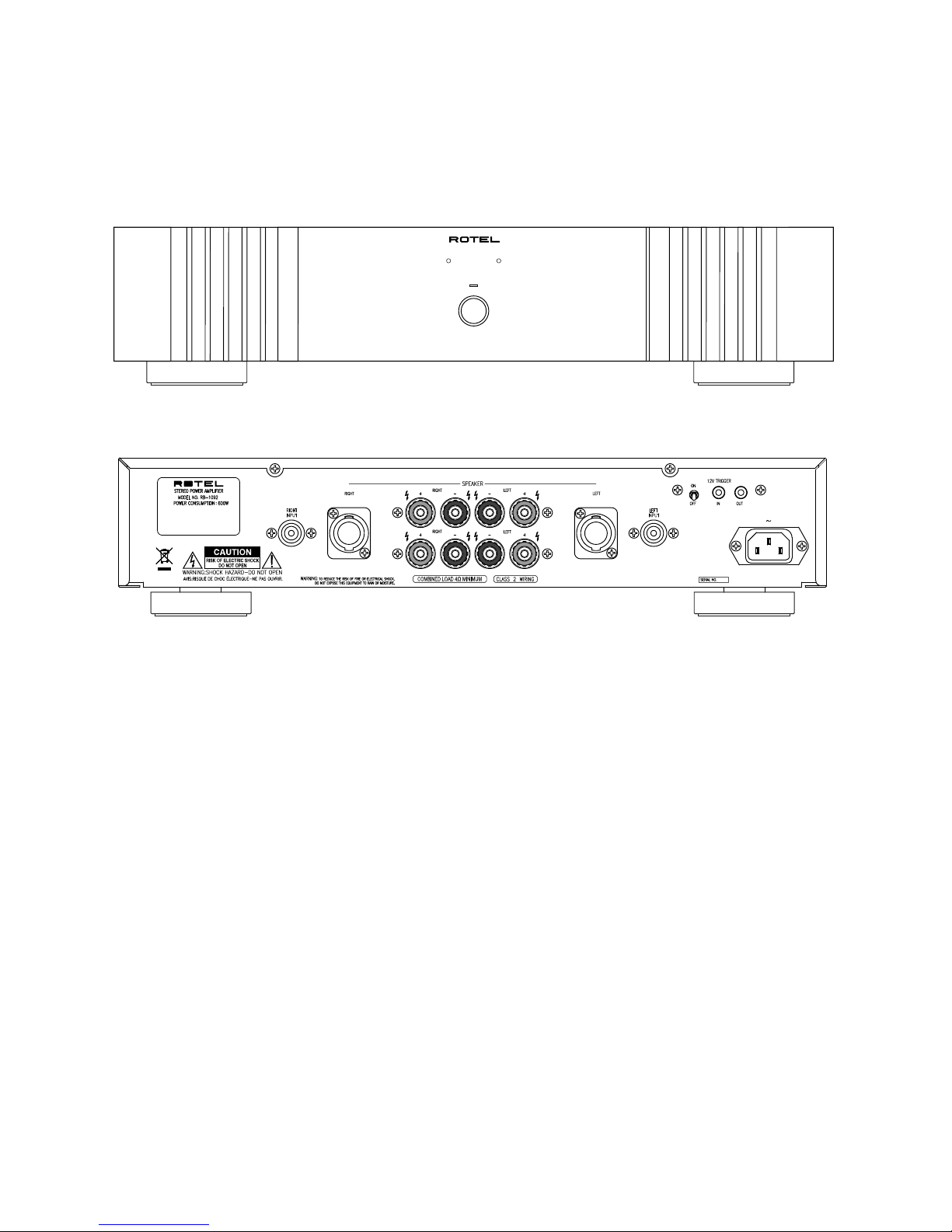
STE REO PO WER AMPL IFIER RB-1 092
POWE R
PRO TECTIO N
L
R
Please be requested:
When the fault are in the 1000ASP module,
replace the module and send back the modules later.
History to RB-1092v02 from RB-1092:
AC Line is replaced with three conductors from two conductors.
Appearance
RB-1092v02
Page 3

Parts List 1/2
RB-1092
SYMBOL PARTS NO. DESCRIPTION
501 X-1438-C PCB ASSY
A,B 013 4TTU-13 PCB SUPPORT
T101 022 T-1075NO2 SUB TRANSFORMER
IC101 031 PC817X2 IC (PHOTO COUPLER) PC817X2J000F
Q101 032 TC3708-ST TRANSISTOR 2SC3708AA-ST
D102,103,104,106,107 034 T1N4148-86 DIODE 1N4148TAP-50
D105 034 TRD12JST1 ZENER DIODE 12V (AB2)
D101 034 W02M POWER DIODE 1.5A 200V
C101 041 TUTES1E471-7TS ELECTROLYTIC CAPACITOR 25V470uF
C102,103 044 DE1307E472M SPARK KILLER 4700pF
R105 053 CR14-221J-A CANBON RESISTOR 1/4W 220
(R103) 053 CR14-272J-A CANBON RESISTOR 1/4W 2.7K
(R103) 053 CR14-472J-A CANBON RESISTOR 1/4W 4.7K
R102 053 CR16-333J-A CANBON RESISTOR 1/4W 33K
R101,109 054 1WS120JF MOF RESISTOR 1W 120
R104 054 1WS1KJF MOF RESISTOR 1W 1K
R107,108 054 ERQ12AJ2R2P FUSIBLE RESISTOR 1/2W 2.2
RY101,102 063 OZT-SS-112LM1 RELAY 12V TV8
S101 064 C-4613A01 TOGGLE SWITCH 200MDP1T2B2M7RE
TJ101,TJ102 065 YKB21-5103A 3.5Φ JACK
K102 068 B2B-EH CONNECTOR POST 2P
K101 068 B3B-EH CONNECTOR POST 3P
AC1,AC2 068 C-3683#1 PCB TERMINAL 2P P=7.5 TP WE-11 I-752NA
501 X-1445 PCB ASSY
L201,202 021 LF174A00 SPEAKER COIL
Q201-203,206 032 TA608-FG TRANSISTOR 2SA608KAA-FG
Q207,208 032 TC3708-ST TRANSISTOR 2SC3708AA-ST
Q204,205,209,210 032 TC536-FG TRANSISTOR 2SC536KAA-FG
D201,202 034 T1N4148-86 DIODE 1N4148TAP-50
C201,202 041 TUTES1E470-7TF ELECTROLYTIC CAPACITOR 25V47uF
C901 044 DE1307E472M SPARK KILLER 4700pF
R203-212,215,216 053 CR14-103J-A CANBON RESISTOR 1/4W 10K
R219,220 053 CR14-222J-A CANBON RESISTOR 1/4W 2.2K
R201,202,213,214,217,218 053 CR14-473J-A CANBON RESISTOR 1/4W 47K
S901 061 C-4176A08 POWER SWITCH PS3-22SPA-P7CZ TV-8 (PCB)
RY201,202 063 DE2TU-12 RELAY DE12D2-OT(M)
K209,210 067 C-4761A01 4P SPEAKER TERMINAL
K205-208 068 B2B-EH CONNECTOR POST 2P
011 FP-590-B BLACK PANEL ASSY
011 FP-590-S SILVER PANEL ASSY
011 VP3-01A00 H/S PANEL
012 RV4-09A00 PUSH BUTTON 14Φ (BLACK)
012 RV4-09A01 PUSH BUTTON 14Φ (SILVER)
014 VP3-09A00 UPPER COVER
019 C-4714A00 POWER KNOB RING 14Φ (BLACK)
019 C-4714A01 POWER KNOB RING 14Φ (SILVER)
019 PK4-07A00T METAL FOOT 60Φ
034 LTL1214A LED (RED) 2F
034 SEL1124R LED (RED) 1x5
034 SEL1E24W LED (BLU) 1x5
036 5HT10-R FUSE 250V10AH for 120V
036 5HT6.3-R FUSE 250V6.3AH for 230V
066 C-4641A01 1P PIN JACK (WHT)
069 C-4629A01 AC 2P INLET 6102.3100 (WIRING) for RB-1092
069 C-4637A00 AC 3P INLET 0707-1-CW for RB-1092v02
016 X-1438A01-02 PCB ASSY
O T H E R S
016 X-1445A01-03 PCB ASSY
Page 4

Parts List 2/2
RB-1092
SYMBOL PARTS NO. DESCRIPTION
072 4TR-2489 3.5mm PLUG SHIELD CORD
072 C-4621A03 AC CORD SET (SJT AWG16) for RAA (RB-1092)
072 C-4392A04 AC CORD SET (SJT AWG14) for RAA (RB-1091v02)
072 C-4622A02 AC CORD SET for AUSTRALIA (RB-1092)
072 C-4423A04 AC CORD SET for AUSTRALIA (RB-1092v02)
072 C-4624A03 AC CORD SET for EUROPE (RB-1092)
072 C-4393A04 AC CORD SET for EUROPE (RB-1092v02)
072 C-4623A02 AC CORD SET for UK (RB-1092)
072 C-4639A02 AC CORD SET for UK (RB-1092v02)
081 VQ3-03A00 INSIDE CARTON
081 VQ3-04A00 SHIPPING CARTON
081 ZE-216 ETHAFOAM MOULDING
082 OMRB-1092-1 OWNER'S MANUAL (EFGISDSwR)
092 ICEPOWER1000ASP DIGITAL AMP ASSY (WITH POWER SUPPLY)
Page 5

RB-1092
SYMBOL PARTS DESCRIPTION
011 FP-590-B BLACK PANEL ASSY
011 FP-590-S SILVER PANEL ASSY
011 VP3-01A00 H/S PANEL H150
013 VP3-03A00 SUB PANEL HOLDER (BLK)
013 VP3-03A01 SUB PANEL HOLDER (SLV)
012 RV4-09A00 PUSH BUTTON 14F (BLK)
012 RV4-09A01 PUSH BUTTON 14F (SLV)
034 SEL1124R LED (RED) 1X5
034 SEL1E24W LED (BLU) 1X5
Addendum List for Black and Silver
Panel Assy is included:
Knob Ring
LED
Page 6

Destination setting
Connecting Fuse 5HT6.3-R for 230V destination
Connecting Fuses 5HT10-R for 115V Destination
RB-1092
1. find the FUSE in the 092 ICEPOWER1000ASP.
2. Set the Fuse to the destination country voltage on the PCB.
3. Replace the fuse value to the destination. 5HT10-R for 115V and 5HT6.3 for 230V on both PCB's.
4. Rewire the Jumper wire on the PCB 016 X-1438A01. Use J101 for 115V and J102 for 230V.
Page 7

1
2
4
5
6
PIN JACK (L)
L (P2)
CNT ASSY
PCB,etc X-1445-01 X-1438-011000ASP
068 C-4897A01
(9P-2P3P 120mm)
3
L (P4)
X-1445-01 (K201)
068 C-4896A01
(4P 160mm)
R (P4)
X-1445-01 (K202)
068 C-4896A01
(4P 160mm)
L (P1)
X-1445-01 (K203)
068 C-4896A03
(6P-3P 60mm)
R (P1)
X-1445-01 (K204)
068 C-4896A03
(6P-3P 60mm)
X-1438-02 (K103)
068 C-4588A09
(3P 420mm)
1000ASP (L-P3)
068 C-4666A07
(6P 330mm)
1000ASP (R-P3)
068 C-4666A08
(6P 520mm)
7
1
2
4
5
6
POWER LED
K102
AC1-1
AC2-1
L
CNT ASSY
PCB,etc X-1445-01 ACINLETX-1438-01
X-1445-03(18)
X-1445-03(17)
ACINLET(N)
K208
068 C-4586A06
(2P 420MM YEL/BLK)
PROTECTION LED(R)
068 C-4586A07
(2P 700MM BLK/ORG)
3
K207
PROTECTION LED(L)
068 C-4586A08
(2P 900MM BLK/RED)
#9(BLK 500MM)
7
E
CHASSIS BODY(GND)
#29(GRN/YEL 100MM)
#11(BLK 440MM)
#31(WHT 160MM)
(2P 420MM YEL/BLK)
K205
PIN JACK (R)
R (P2)
068 C-4897A01
(9P-2P3P 120mm)
K206
8
9
K101
AC1-2 (BRN)
AC2-2 (BLU)
AC1-2 (BRN)
AC2-2 (BLU)
501 X-1438-01
K101
AC2
AC1
1 2
1 2
BRNx2
BLUx2
501 X-1445-01
501 X-1445-02
K202
K204
K206
K208
K201
K203
K205
K207
P3
P4
P1
P2
P3
P4
P1
P2
Top View
501 X-1438-02
K103
K102
1 2
1 2
WHT #31
throu under the PCB
N
(WHT)
L(BLK)#9
BLK #11
LCH RCH
RCHLCH
E
#29(GRN/YEL)
1000ASP
1000ASP
Wiring-1
Wiring-2
Wiring Diagram
RB-1092v02
Page 8

PCB Assembly
016 X-1445A01 - 03
RB-1092
016 X-1438A01 -02
Sub Transformer PCB
Output and Protection PCB
16
15 1314
016X-1445A02
016X-1445A01
4 62121087911135
17
18
K14K13
K16
K15
K6K4K2K12K10K8K7K9K11K1K3K5
K17
K18
S901
C901
K210
K209
L201
L202
K203
C201
Q201
R207
R205
D201
RY201
R219
Q209
R217
R215
Q207
R213
R211
Q203
C205
Q205
C203
R209
R203
R201
R202
Q202
R204
K207
K205
C202
Q206
C206
R210
C204
Q204
R212
R214
R216
Q208
R218
Q210
R220
K208K206
K201
K202
R206
K204
R208
D202
RY202
016X-1445A03
Page 9

FUSE
FUSE
C30B
Schematic
Diagram
RB-1092v02
 Loading...