

Rosemount 6888Xi Reference Manual
Rosemount™ 6888Xi
Advanced Electronics for Zirconium Oxide
Reference Manual
0809-0100-4892
0
Rev. AB
January 2019
Flue Gas O
Probes
2

B Table of Contents

Essential Instructions
Read this page before proceeding
Emerson designs, manufactures and tests its products to meet many national and international
tandards. Because these instruments are sophisticated technical products, you MUST properly
s
install, use, and maintain them to ensure they continue to operate within their normal specifications. The following instructions MUST be adhered to and integrated into your safety program
when installing, using, and maintaining Rosemount products. Failure to follow the proper instructions may cause any one of the following situations to occur: Loss of life; personal injury; property
damage; damage to this instrument; and warranty invalidation.
• Read all instructions prior to installing, operating, and servicing the product.
• If you do not understand any of the instructions, contact your Emerson representative for clarification.
• Follow all warnings, cautions, and instructions marked on and supplied with the product.
• Inform and educate your personnel in the proper installation, operation, and maintenance of
the product.
• Install your equipment as specified in the Installation Instructions of the appropriate Reference
Manual and per applicable local and national codes. Connect all products to the proper electrical and pressure sources.
• To ensure proper performance, use qualified personnel to install, operate, update, program,
and maintain the product.
• When replacement parts are required, ensure that qualified people use replacement parts specified by Emerson. Unauthorized parts and procedures can affect the product's performance,
place the safe operation of your process at risk, and VOID YOUR WARRANTY. Look-alike substitutions may result in fire, electrical hazards, or improper operation.
• Ensure that all equipment doors are closed and protective covers are in place, except when
maintenance is being performed by qualified persons, to prevent electrical shock and personal
injury.
The information contained in this document is subject to change without notice.
S
E
OT
N
tion
ra
for ope
se
n
e
ic Lic
ph
Gra
th
wi
.0
2
are
oftw
m S
e
t
s
y
d to S
de
upgra
t be
us
tor m
ica
n
u
omm
d C
l
Fie
5
7
3
e
Th
.
e
bov
or a
0
8.
MS
d to A
de
upgra
t be
us
m
are
softw
MS
A
e
Th
.
ics
tron
c
e
l
E
i
X
8
8
8
t 6
n
u
mo
ose
R
e
th
th
wi
tor
ica
n
u
omm
d C
l
5 Fie
7
3
e
th
r (GSC) a
e
t
n
e
C
e
ic
v
r
e
S
bal
o
’s Gl
son
r
me
t E
ac
t
on
C
software to System Software 2.0 with Graphic License.
Essential Instructions I
t 1
to upgra
4
1
3
8
-
3
3
8
-
0
0
8
-
de

II Table of Contents

Reference Manual Table of Contents
00809-0100-4892 January 2019
Contents
Essential Instructions .....................................................................................................I
Section i: Introduction
Preface .........................................................................................................................1
Definitions....................................................................................................................1
Symbols........................................................................................................................2
Overview......................................................................................................................2
Technical Support Hotline............................................................................................2
Section 1: Description and Specifications
1.1 Component Checklist...................................................................................................3
1.2 System Overview..........................................................................................................3
1.2.1 Power Supply –Current Loop Wiring ..............................................................3
1.2.2 System Configurations....................................................................................4
1.2.3 Automatic Calibration.....................................................................................5
1.2.4 Communication Options ................................................................................6
1.3 Specifications...............................................................................................................8
Section 2: Installation
2.1 System Considerations...............................................................................................12
2.2 Mechanical Installation...............................................................................................12
2.3 Electrical Installation ..................................................................................................15
Section 3: Configuration, Startup and Operation
3.1 Overview ...................................................................................................................25
3.2 Startup .......................................................................................................................25
3.2.1 Configuration................................................................................................26
3.2.2 Operation......................................................................................................26
3.2.3 Startup Display..............................................................................................26
3.2.4 Error Conditions............................................................................................27
3.2.5 Keypad..........................................................................................................27
3.2.6 Password Protection. ....................................................................................34
3.3 Optional Advanced Features......................................................................................34
3.3.1 Extended Temperature ................................................................................35
3.3.2 Stoichiometer...............................................................................................35
3.3.3 Programmable Reference.............................................................................36
3.3.4 Plugged Diffusion Element Diagnostic..........................................................36
3.4 System Parameter Descriptions ................................................................................40
3.5 Probe Parameter Descriptions. ..................................................................................40
3.6 Operation Via HART/AMS ..........................................................................................40
3.6.1 Field Communicator Signal Line Connections...............................................48
3.6.2 Field Communicator Menu Trees..................................................................48
Table of Contents III

Table of Contents Reference Manual
January 2019 00809-0100-4892
3.7 Parameter Setup ........................................................................................................48
3.7.1 Test Gas Values .............................................................................................48
.7.2Test Gas Times..............................................................................................53
3
3.7.3 Output Tracking During Calibration..............................................................54
3.7.4 Tolerance Check............................................................................................54
3.7.5 Alarm Relay Output Configuration................................................................55
3.7.6 Analog Output Configuration....................................................................... 57
3.7.7 Autocalibration ............................................................................................ 58
3.7.8 Calibration Recommended Setup................................................................ 58
3.7.9 Calibration Acknowledged Setup................................................................. 59
3.7.10 Plug Diffuser Diagnostic................................................................................59
3.7.11 Low Temperature Set Point...........................................................................61
3.8 Calibration - General ..................................................................................................62
3.8.1 General..........................................................................................................62
3.8.2 Calibration Procedure ...................................................................................62
3.8.3 Calibration Log..............................................................................................67
3.8.4 Reset Calibration...........................................................................................67
3.9 D/A Trim. ...................................................................................................................68
Section 4: Troubleshooting
4.1 Overview of Operating Principles...............................................................................71
4.2 General.......................................................................................................................72
4.2.1 Grounding.....................................................................................................72
4.2 .2 Electrical Noise..............................................................................................72
4.2.3 Electrostatic Discharge .................................................................................72
4.3 Alarm Indications .......................................................................................................72
4.4 Identifying and Correcting Fault Indications ..............................................................73
4.5 Calibration Passes, But Still Reads Incorrectly ............................................................74
4.5.1 Probe Passes Calibration, O2Still Reads High................................................75
4.5.2 Probe Passes Calibration, O2Still Reads Low.................................................76
4.5.3 How do I detect a plugged diffuser?..............................................................76
4.5.4 Can I calibrate a badly plugged diffuser?.......................................................76
Section 5: Maintenance and Service
5.1 Overview....................................................................................................................79
5.2 Maintenance Intervals................................................................................................79
5.3 Calibration..................................................................................................................80
5.3.1 Automatic Calibration...................................................................................80
5.3.2 Manual Calibration........................................................................................80
5.4 Replacement Parts.....................................................................................................81
5.5 6888Xi Components Replacement............................................................................81
5.5.1 I/O Board Replacement.................................................................................81
IV Table of Contents

Reference Manual Table of Contents
00809-0100-4892 January 2019
5.5.2 AC Relay Board Replacement........................................................................85
5.5.3 Power Supply Board Replacement................................................................87
5.5.4 Front Panel Replacement..............................................................................88
5.5.5 DR Board Replacement.................................................................................90
Section 6: Replacement Parts
6.1 6888Xi Electronics .....................................................................................................93
6.2 Calibration Components............................................................................................93
Section 7: Optional Accessories
7.1 HART Handheld 375/475 Field Communicator .........................................................95
7.2 Asset Management Solutions (AMS)..........................................................................95
7.3 By-Pass Packages........................................................................................................95
7.4 SPS 4001B Single Probe Autocalibration Sequencer..................................................96
7.5 IMPS 4000 Intelligent Multiprobe Test Gas Sequencer. .............................................97
7.6 O2Calibration Gas......................................................................................................98
7.7 OxyBalance Display and Averaging System................................................................99
Appendix A: Safety Data
A.1 Safety Instructions ...................................................................................................100
Appendix B: Return of Material
B .1 Returning Material ...................................................................................................101
Appendix C: EU Declaration of Conformity...........................................................102
Appendix D: China RoHS Table......................................................................................103
Table of Contents V

Table of Contents Reference Manual
January 2019 00809-0100-4892
VI Table of Contents

Reference Manual Section i: Introduction
00809-0100-4892 January 2019
Section i: Introduction
Preface
The purpose of this manual is to provide information concerning components, functions, installation and maintenance of the 6888Xi Electronics. Some sections may describe equipment not
used in your configuration. The user should become thoroughly familiar with the operation of
this module before operating it. Read this instruction manual completely.
Definitions
The following definitions apply to WARNINGS, CAUTIONS, and NOTES
WARNING
Highlights an operation or maintenance procedure, practice, condition, statement, etc. If not strictly
observed, could result in injury, death, or long-term health hazards of personnel.
CAUTION
Highlights an operation or maintenance procedure, practice, condition, statement, etc. If not strictly
observed, could result in damage to or destruction of equipment, or loss of effectiveness.
NOTE
Highlights an essential operating procedure, condition, or statement.
Introduction 1

Section i: Introduction Reference Manual
R
ISKOFELECTRICAL SHOCK
WARNING:REFER TOINSTRUCTIONMANUAL
PROTECTIVECONDUCT OR TERMINAL
E
ARTH(GROUND) TERMINAL
:
:
:
:
January 2019 00809-0100-4892
Symbols
Overview
The Rosemount 6888Xi is specifically designed to control a zirconium oxide probe for measuring
oxygen, usually the O2 remaining from a combustion process. Call the Rosemount Customer
Support Center (CSC) to get recommendations for other oxygen probes.
Phone : +1 855 724 2628
The 6888Xi electronics has several main functions:
1. Heater Control - The electronics receives a type K thermocouple input from an O2 probe and
switches power on and off to the probe's heater in order to maintain a temperature setpoint
of 736 °C.
2. Signal Conditioning - The electronics receives the raw millivolt signal from the O2 sensing
cell, then linearizes and amplifies the signal to provide a linear 4-20 mA output signal used
for recording or as an input into a DCS system for control purposes.
3. Calibration - A bottled calibration gas of known value is typically flowed into the probe's sensor to verify that it is reading correctly. If the signal is out of calibration, the calibration gas is
used to adjust the 4-20 mA output signal. During calibration the 6888Xi prompts the technician to flow two calibration gases into the probe and, with the calibration gases flowing,
automatically adjusts the O2 signal. With the addition of a Single Probe Sequencer (SPS), the
6888Xi Advanced Electronics can also switch the calibration gases on and off.
4. Diagnostics - Multiple alarms are available for display. The alarm displays are intended to
assist a technician in locating where an instrument problem may reside.
The Rosemount 6888Xi Advanced Electronics has been verified to operate the following probes:
• Westinghouse 218 and World Class (115 V heater only)
• Rosemount Oxymitter and 6888
• Yokogawa
The Rosemount 6888Xi Advanced Electronics will not operate the following probes:
• World Class (44 V Heater)
• XSTREAM O2 Probe (Transmitter, Integral Electronics)
Technical Support Hotline
For assistance with technical problems, please call the Customer Support Center (CSC).
Phone: +1 855 724 2638
In addition to the CSC, you may also contact Field Watch. Field Watch coordinates Emerson’s
field service throughout the U.S. and abroad.
Phone: 1-800-654-RSMT (1-800-654-7768)
2 Introduction
e-mail: gas.csc@emerson.com
Reference Manual Section 1: Description and Specifications
00809-0100-4892 January 2019
Section 1: Description and Specifications
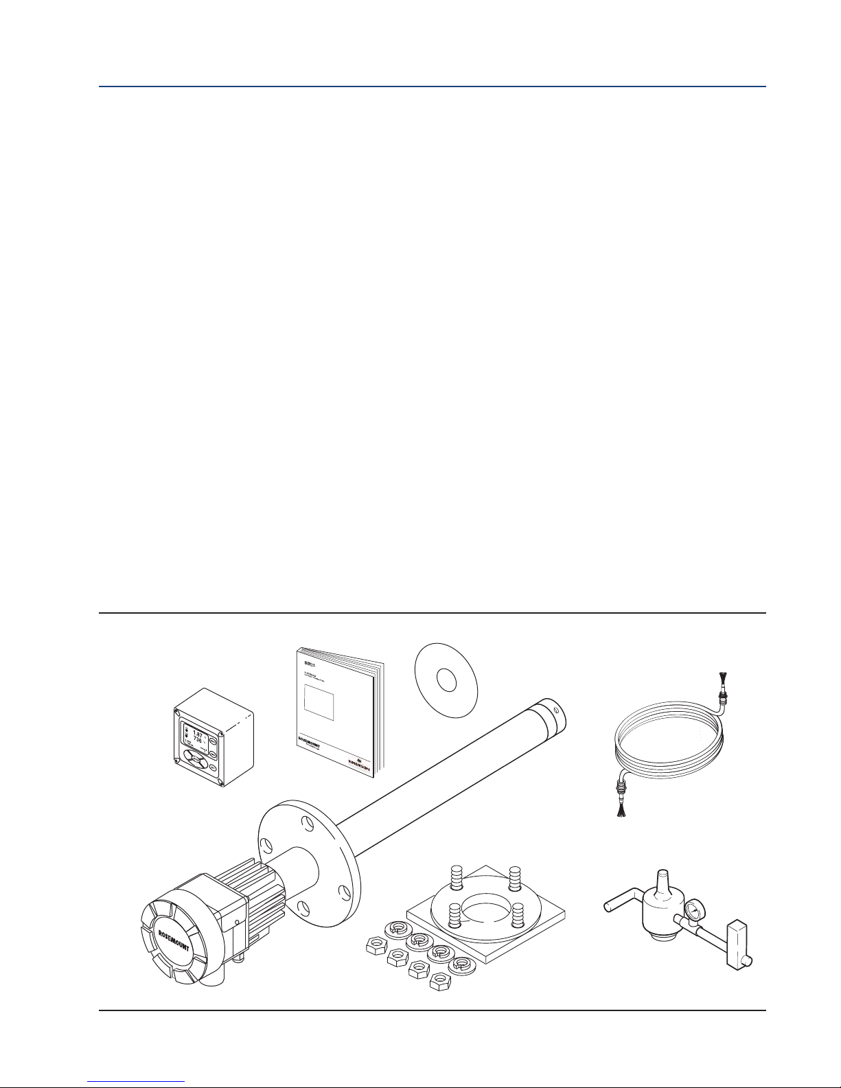
1.1 Component Checklist
A typical Rosemount O2 Combustion Flue Gas Transmitter should contain the items shown in
Figure 1-1. A complete Oxygen Analyzer system will include some or all of the equipment
shown. However, this manual describes item 8 only. Record the part number, serial number, and
order number for the Rosemount 6888Xi Advanced Electronics in the table located on the back
cover of this manual.
Also, use the product matrix (Table 1-1) at the end of this section to compare your order number against your unit. The first part of the matrix defines the model. The last part defines the various options and features. Ensure the features and options specified by your order number are
on or included with the unit.
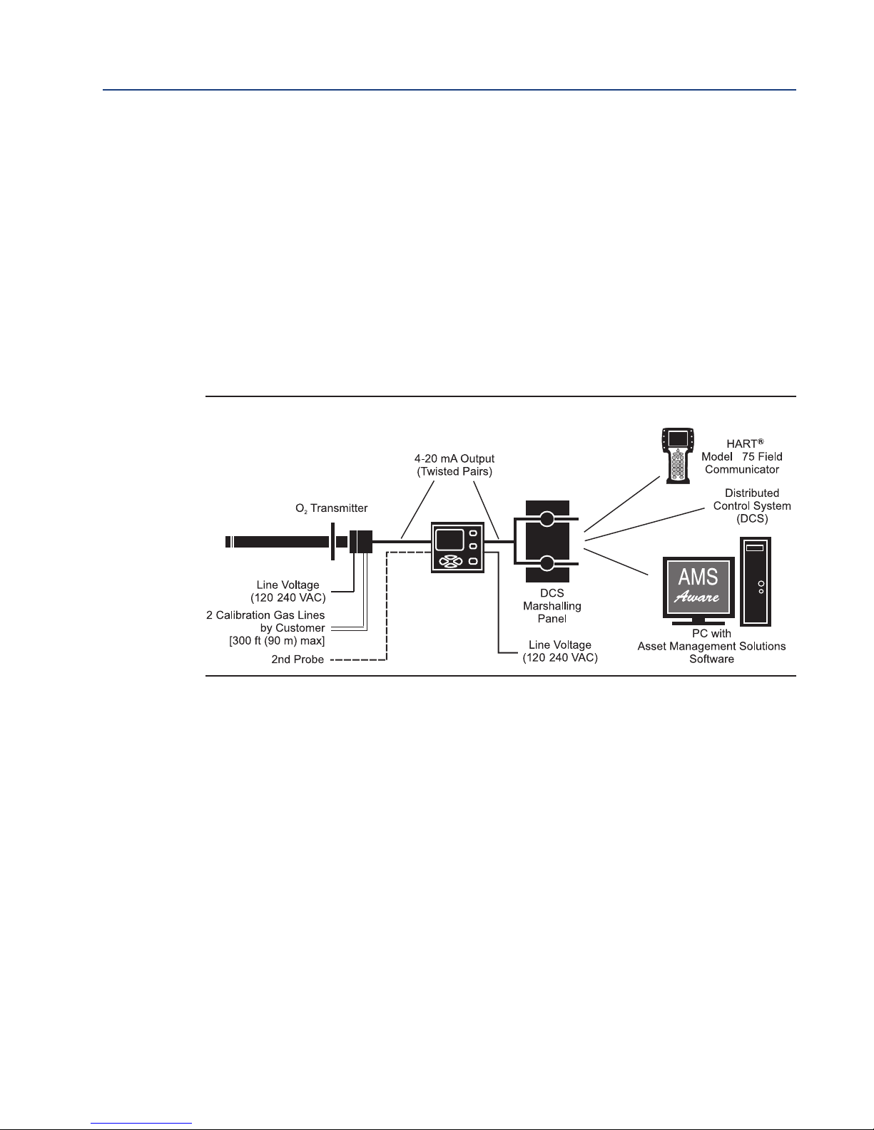
1.2 System Overview
1.2.1 Power Supply-Current Loop Wiring
This Reference Manual is designed to supply details needed to install, start up, operate, and
maintain the Rosemount 6888Xi Advanced Electronics. Signal conditioning electronics outputs a
4-20 mA signal representing an O2 value. This information, plus additional details, can be
accessed with the handheld HART Model 375/475 Field Communicator or Asset Management
Solutions (AMS) software.
Figure 1-1. Typical System Package
Quick Start
Manual
Optional 6888Xi
Advanced Electronics
Optional Mounting or
6888A Probe
Full Instruction
Manual DVD
Adapter Plate
Optional Traditional
Architecture Cable
Description and Specifications 3
Optional Reference &
Calibration Gas
Accessories
Section 1: Description and Specifications Reference Manual
6888A
6888Xi
Advanced
Electronics
4
/
/
January 2019 00809-0100-4892
1.2.2 System Configurations
Integral Transmitter Electronics,
HART and 6888Xi Communications
The Rosemount 6888Xi Advanced Electronics, Figure 1-2, provide a local display/keypad for
setting up, calibrating, and displaying O2, and for diagnosing probe problems. The 6888Xi also
offers additional features including a "Calibration Recommended" diagnostic, fully automatic
calibration, optional flame safety interface (single probe version only), extended process
temperature capability, stoichiometer, programmable reference, and plugged diffusor. These
additional features will be discussed in other sections of this manual. The 6888Xi can be
purchased to operate a single probe, or as a dual channel unit to run two probes.
Figure 1-2. 6888A with Integral Transmitter Electronics and
Optional 6888Xi Advanced Electronics
Traditional Architecture, HART and 6888Xi Communications
Some customers prefer not to mount electronics onto the probe, so a "traditional architecture"
version is offered. This probe sends raw millivolt signals via a 7-conductor cable to the 6888Xi
electronics, Figure 1-3, which does all heater control and signal conditioning in addition to its
display/keypad functions. The 6888Xi Advanced Electronics is offered to support direct replacement probes with 120 volt heaters.
4 Description and Specifications

Reference Manual Section 1: Description and Specifications
6888Xi
Advanced
Electronics
/
00809-0100-4892 January 2019
Figure 1-3. Direct Replacement Probe With Traditional Architecture Electronics
1.2.3 Automatic Calibration
Calibrations consist of introducing bottled gases of known value into the probe so the
electronics can make automatic adjustments to the O2readings to match the bottled gas value.
0.4% O2and 8% O2(balance nitrogen) gases are recommended. Never use nitrogen as a
calibration gas.
Flowmeters (for calibration gases) and regulators and flowmeters (for reference air) are available
as loose components, mounted into an optional manual calibration switching panel, or as a fully
automatic calibration system, Figure 1-4, where calibration solenoids are switched from the
6888Xi Advanced Electronics. See IM-106-340AC, SPS 4001B Single Probe Autocalibration
Sequencer or IM-106-400IMPS, IMPS 4000 Intelligent Multiprobe Test Gas Sequencer, for
additional details.
Figure 1-4. 6888A Probe with Optional 6888Xi Advanced Electronics and
Calibration Accessories
O2 Probe
6888Xi
Advanced Electronics
Description and Specifications 5

Section 1: Description and Specifications Reference Manual
January 2019 00809-0100-4892
1.2.4 Communication Options
Data Communications
An operator can configure and troubleshoot the O2 Probe system in one of two ways:
1. Using the 6888Xi Advanced Electronics keypad and display to access the following optional
advanced features:
• Probe configuration
• Fully automatic calibration
• Failure diagnostics
• Flame safety interface
• High temperature operation [above 700 °C (1292 °F) standard temperature].
• Stoichiometer feature provides the ability to indicate O2 efficiency when the combustion
process goes into reducing conditions (0% O2).
• Programmable reference provides enhanced accuracy when measuring at or near O2
level (20.95% O2).
• Plugged diffusor diagnostics
2. Using the HART Interface. The 6888Xi’s 4-20 mA output line transmits an analog signal proportional to the oxygen level. The HART output is superimposed on the 4-20 mA output
line. This information can be accessed through the following:
• Rosemount Model 375/475 Field Communicator - The handheld communicator requires
Device Description (DD) software specific to the 6888Xi. The DD software will be supplied with many Model 375/475 units but can also be programmed into existing units at
most Emerson service offices. See Section 4, Startup and Operation, for additional information.
• Personal Computer (PC) - The use of a personal computer requires AMS software available
from Emerson.
• Delta V and Ovation Distributed Control System (DCS) with AMS-inside capability.
NOTE
The 375 Field Communicator must be upgraded to System Software 2.0 with Graphic License for operation with the 6888Xi. The AMS software must be upgraded to AMS 8.0 or above.
Contact Emerson’s Global Service Center (GSC) at 1-800-833-8314 to upgrade the 375 Field
Communicator software to System Software 2.0 with Graphic License.
6 Description and Specifications
Reference Manual Section 1: Description and Specifications
A
nal
y
t
i
c
al
AAnAnaAnalAnalyAnalytAnalytiAnalyticAnalyticaAnalytical
00809-0100-4892 January 2019
3. The 6888Xi can also transmit HART information wirelessly via a wireless THUM Adapter,
Figure 1-5. The THUM Adapter threads into the
FIGURE 1-5. Wireless THUM Adapter with
6888Xi
6888Xi conduit port and converts the 4-20 mA
O2 signal to a wireless protocol. All other HART
information is also transmitted.
In addition to the wireless THUM Adapter, a
hard-wire connection of the 4-20 mA signal to
the DCS may be used at the same time. More
detailed information regarding the application
of the THUM Adapter is available in Product
Data Sheet 00813-0100-4075.
4. The 6888Xi can be configured to communicate with a 6888A FOUNDATION Fieldbus probe.
Refer to section 3.2.1 Configuration to set up for FOUNDATION Fieldbus communications.
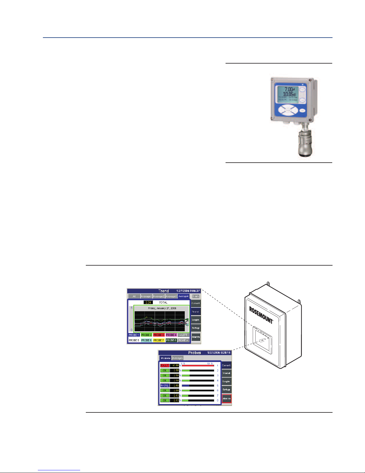
Optional OxyBalance Display and Averaging System
Receives up to eight 4-20 mA signals from individual 6888Xi units. Trends individual outputs and
calculates four programmable averages as additional 4-20 mA outputs. OxyBalance graphic displays are shown in Figure 1-5. See IM-106-4050, OxyBalance Oxygen Display and Averaging
System, for additional details.
FIGURE 1-5. OxyBalance Displays
Description and Specifications 7
Section 1: Description and Specifications Reference Manual
January 2019 00809-0100-4892
1.3 Specifications
easurement Specifications
M
Net O2 Range: 0 to 50% O2 user scalable
-2 to 50% O2 user scalable with stoichiometer
Lowest Detectable Limit: 0.01% O2
Signal Stability: ±0.03% O2
Accuracy in Reducing Conditions: ±10% of reading or 0.1% O2
System Response in Reducing Conditions: going from oxidizing to reducing -T90 in 120 seconds
going from reducing to oxidizing -T90 in 30 seconds
Ambient Temperature Effect on Xi 4-20 mA Signal: less than 0.0025% O2 per degree Celsius
Environmental Specifications
6888Xi Advanced Electronics: Type 4X, Polycarbonate Material
Ambient Temperature Limits: -20 °C to 50 °C (-4 °F to 122 °F)
-20 °C to 70 °C (-4 °F to 158 °F) as measured by electronics
6888Xi LCD display:
Ambient Temperature Limits -20 °C to 55 °C (-4 °F to 131 °F)
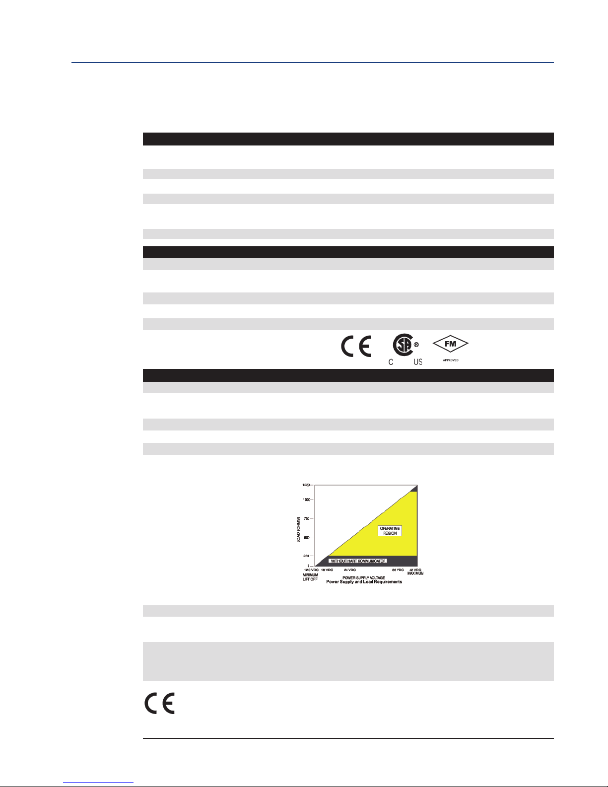
General Purpose Certifications:
Installation Specifications
Mounting: Panel, wall, or pipe.
Reference Air: 2 scfh (1L /min), clean, dry, instrument-quality air
(20.95% O2), regulated to 5 psi (34 kPa)
Calibration: Semi-automatic or automatic
Cal Gases: 0.4% O2 and 8% O2, balance N2 recommended
Traditional Architecture Cable 200 ft (61 m) maxmum length
Transmitter Electrical Power: 12 - 24 VDC (loop-powered from control room or 6888Xi)
Electrical Power for 6888Xi: 120/240VAC ±10%, 50/60 Hz
Power Consumption of 6888Xi: 12 VA maximum or 1020 VA maximum with Traditional
Architecture,120V Probes
Alarm Relay Outputs: Two provided - 2 Amperes, 30 VDC, Form-C
Optional Loss of Flame Input: Internally powered input to remove heater power
actuated via dry contact output from user’s flame scanner
Emerson has satisfied all obligations from the European legislation to harmonize the
product requirements in Europe. All static performance characteristics are with operating variables constant. Specifications subject to change without notice.
8 Description and Specifications

Reference Manual Section 1: Description and Specifications
00809-0100-4892 January 2019
Table 1-1. Product Matrix, Advanced Electronics
6888Xi Advanced Electronics
Code Remote Type
1OXY Single Channel O2
2OXY Single Channel O2 with Flame Safety Interlock for Heater
3OXY Dual Channel O
4OXY Single Channel O2, Traditional Architecture for 120V Probes
Code Mounting
00 No Hardware
01 Panel Mount Kit with Gasket
02 2" Pipe / Wall Mount Kit
Code Cable
00 No Cable
10 20' (6m) Cable
11 40' (12m) Cable
12 60' (18m) Cable
13 80' (24m) Cable
14 100' (30m) Cable
15 150' (45m) Cable
16 200' (60m) Cable
Code Stoichiometer Function
00 No
01 Single Channel
02 Dual Channel
Code Programmable Reference Function
00 None
01 Single Channel
02 Dual Channel
Code Extended Temperature Function
00 None
01 Single Channel
02 Dual Channel
Code Plugged Diffuser Diagnostic Function
00 None
01 Single Channel
02 Dual Channel
Description and Specifications 9

Section 1: Description and Specifications Reference Manual
January 2019 00809-0100-4892
Table 1-2. Product Matrix, O2Autocalibration Accessories
XS O2CAL O2 Autocalibration Accessories
Code Single Probe Sequencers Autocalibration Options
00 None
01 SPS 4001B Single Probe Sequencer, general purpose NEMA 4X, includes check valve for probe
Code Intelligent Multiprobe Sequencers (IMPS)
00 None
01 IMPS single-probe, general purpose NEMA 4X, includes check valve for probe
02 IMPS two-probe, general purpose NEMA 4X, includes check valve for probe
03 IMPS three-probe, general purpose NEMA 4X, includes check valve for probe
04 IMPS four-probe, general purpose NEMA 4X, includes check valve for probe
05 IMPS single-probe, 115V heated general purpose NEMA 4X, includes check valve for probe
06 IMPS two-probe, 115V heated general purpose NEMA 4X, includes check valve for probe
07 IMPS three-probe, 115V heated general purpose NEMA 4X, includes check valve for probe
08 IMPS four-probe, 115V heated general purpose NEMA 4X, includes check valve for probe
09 IMPS single-probe, 220V heated general purpose NEMA 4X, includes check valve for probe
10 IMPS two-probe, 220V heated general purpose NEMA 4X, includes check valve for probe
11 IMPS three-probe, 220V heated general purpose NEMA 4X, includes check valve for probe
12 IMPS four-probe, 220V heated general purpose NEMA 4X, includes check valve for probe
TABLE 1-3. Calibration Glass
Part Number Description
1A99119G01 Two disposable calibration gas bottles - 0.4% and 8% O2, balance nitrogen - 550 liters each*
1A99119G02 Two flow regulators for calibration gas bottles
1A99119G03 Bottle rack
*Calibration gas bottles cannot be shipped via airfreight.
10 Description and Specifications

Reference Manual Section 2: Installation
00809-0100-4892 January 2019
Section 2: Installation
WARNING
Before installing this equipment read the "Safety instructions for the wiring and installation
ofthis apparatus" at the front of this Reference Manual. Failure to follow safety instructions
could result in serious injury or death.
WARNING
Install all protective equipment covers and safety ground leads after installation. Failure to
install covers and ground leads could result in serious injury or death.
WARNING
The 6888Xi Advanced Electronics can be installed in general purpose areas only. Do not install
the 6888Xi in hazardous areas or in the vicinity of flammable liquids.
CAUTION
If external loop power is used, the power supply must be a safety extra low voltage (SELV) type.
Installation 11
Section 2: Installation Reference Manual
6888Xi
HART/4-20 mA
Signal
Advanced
Electronics
Line
Voltage
O
2
Probe
Interconnect
Cable
Calibration
Gas
Flowmeter
Pressure
Regulator
Instrument
Air Supply
(Refernce Air)
Adapter Plate
and Flange
Stack
Gases
Duct
January 2019 00809-0100-4892
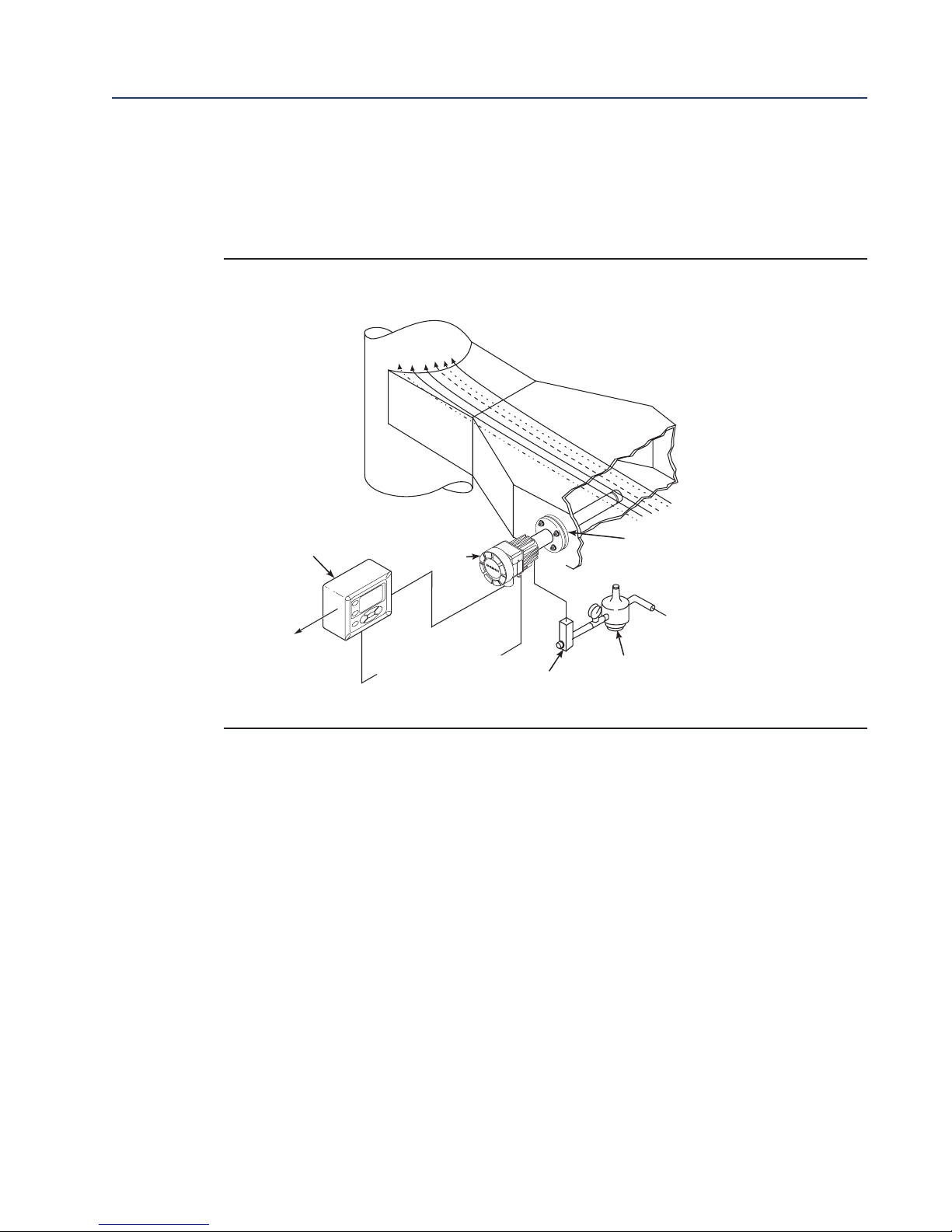
2.1 System Considerations
A typical system installation for a 6888Xi and O2Probe is shown in Figure 2-1.
FIGURE 2-1. Typical System installation
2.2 Mechanical Installation
6888Xi Advanced Electronics
12 Installation
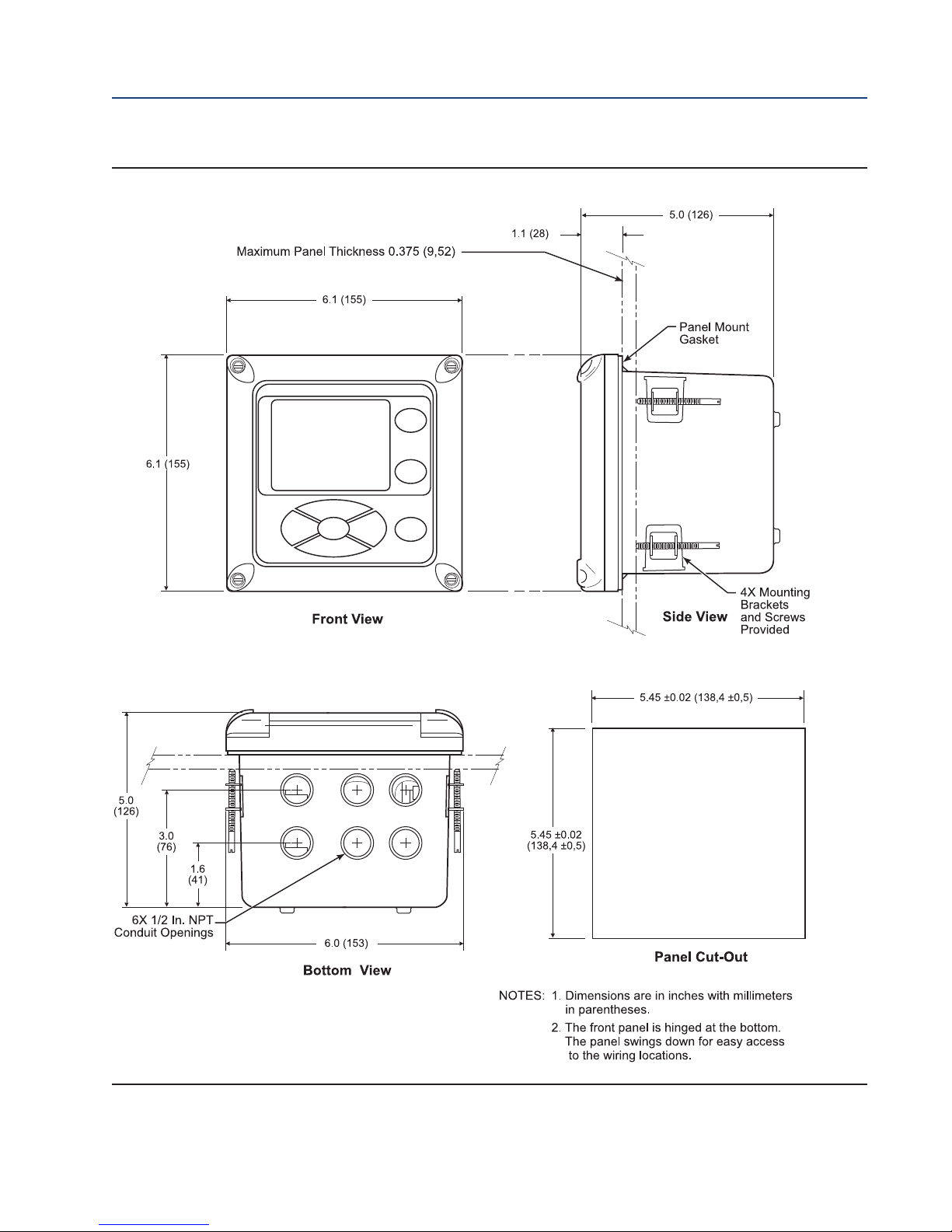
The 6888Xi Advanced Electronics is available in a panel mounting, wall mounting, or pipe
mounting configuration. Refer to Figure 2-2 or Figure 2-3 for the panel, wall, or pipe mounting
details.
1. Ensure all components are available to install the 6888Xi.
2. Select a mounting location near or removed from the O2 Probe. Consider the temperature
limitations of the 6888Xi (see "Specifications") when selecting the mounting location.
3. Mount the 6888Xi at a height convenient for viewing and operating the interface.
Approximately 5 ft (1,5 m) is recommended.
4. The keypad window on the 6888Xi may have interior and exterior protective membranes.
Remove the protective membranes prior to use of the 6888Xi enclosure. Failure to remove
the protective membranes may cause the display to appear distorted. The membrane may
be difficult or impossible to remove after extended use at elevated temperatures.
Reference Manual Section 2: Installation
00809-0100-4892 January 2019
FIGURE 2-2. 6888XI Advanced Electronics - Panel Mounting Details
Installation 13
Section 2: Installation Reference Manual
January 2019 00809-0100-4892
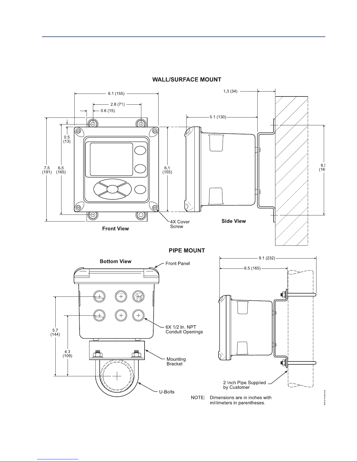
FIGURE 2-3. 6888XI Advanced Electronics - Wall/Surface and Pipe Mounting Details
14 Installation

Reference Manual Section 2: Installation
00809-0100-4892 January 2019
2.3 Electrical Installation
Rosemount 6888Xi Advanced Electronics
All wiring must conform to local and national codes. Multiple wiring diagrams are shown in this
section. Always refer to the diagrams that apply to your transmitter configuration and disregard
all other wiring diagrams.
WARNING
Disconnect and lock out power before connecting the power supply.
WARNING
Install all protective covers and safety ground leads after installation. Failure to install covers and ground
leads could result in serious injury or death.
WARNING
To meet the Safety Requirements of IEC 61010 (EC requirement), and ensure safe operation of this equipment, connection to the main electrical power supply must be made through a circuit breaker (min 10A)
which will disconnect all current-carrying conductors during a fault situation. This circuit breaker should
also include a mechanically operated isolating switch. If not, then another external means of disconnecting
the supply from the equipment should be located close by. Circuit breakers or switches must comply with a
recognized standard such as IEC 947.
NOTE
Line voltage, signal, and relay wiring must be rated for at least 105 °C (221 °F).
NOTE
If metal conduit is used with the 6888Xi the conduit should be reliably bonded to protective
earth. The grounding plate inside the 6888Xi is not bonded to PE and does not provide adequate
grounding.
1. Remove cover screws from the front cover of the 6888Xi. Swing down the front cover of the
interface box.
2. Pull out the I/O board on the right-hand side of the card rack inside the 6888Xi. If your sys-
tem is configured to operate two transmitter probes there are two I/O interface boards.
3. See Figures 2-5, 2-6 and 2-7. Connect the 4-20 mA signal wires at J4 of the I/O board. Attach
the supplied ferrite clamp over the 4-20 mA OUT wires that extend past the shield.
NOTE
Installation of the ferrite clamp over the 4-20 mA OUT wires is required for compliance with the
European EMC Directive.
4. Terminate the shield of the 4-20 mA signal wires at the designated ground terminal of the
6888Xi. Do not allow bare shield wires to contact the circuit boards. Insulate the shield wires
prior to termination.
5. Connect the signal wires from the SPS or IMPS (if used) to the applicable terminals of J3.
Refer to the SPS or IMPS instruction manual for wiring details.
Installation 15
Section 2: Installation Reference Manual
January 2019 00809-0100-4892
6. Connect the customer’s alarm indicator devices to the alarm indicator relay terminals.
7. Reinstall the I/O board in the card rack of the 6888Xi.
8. If your system is configured for two channel operation, repeat steps 2 through 7 to connect
the other signal wires.
9. Remove the connector from the power supply board located on the left-hand side of the
card rack inside the 6888Xi.
10. Connect the line, or L1 wire to the L1 terminal and the neutral, or L2 wire, to the N terminal.
11. Reinstall the power supply connector in the power supply board.
Flame Safety Interlock
A flame safety interlock by Emerson is available for heater power disconnect whenever there is a
loss of the process flame or a heater runaway condition (heater over-temperature) in the O
2
Probe. This input is internally powered by the 6888Xi and is actuated via a dry contact output
from the user’s flame scanner. A closed contact indicates a flame is present. An open contact
indicates a loss of flame.
1. Connect the signal wires from the burner management system flame status output to the
flame status input terminals of J2. The flame status sensing device is supplied by the customer. Refer to the applicable OEM documents for signal wiring details.
2. Remove the J1 and J2 connectors from the AC relay board.
3. Connect the AC line input to the J1 connector.
4. Connect the AC power to the 6888A probe to the J2 connector.
5. Reinstall connector J1 and J2 to the AC relay board.
Traditional Architecture Cable Connections
A traditional architecture configuration is used to provide for remote location of the transmitter
electronics. All electronics are housed inside the 6888Xi. A multi-conductor power/signal cable
connects between the probe and the 6888Xi. Use the following procedure to connect the traditional architecture probe to the 6888Xi.
NOTE
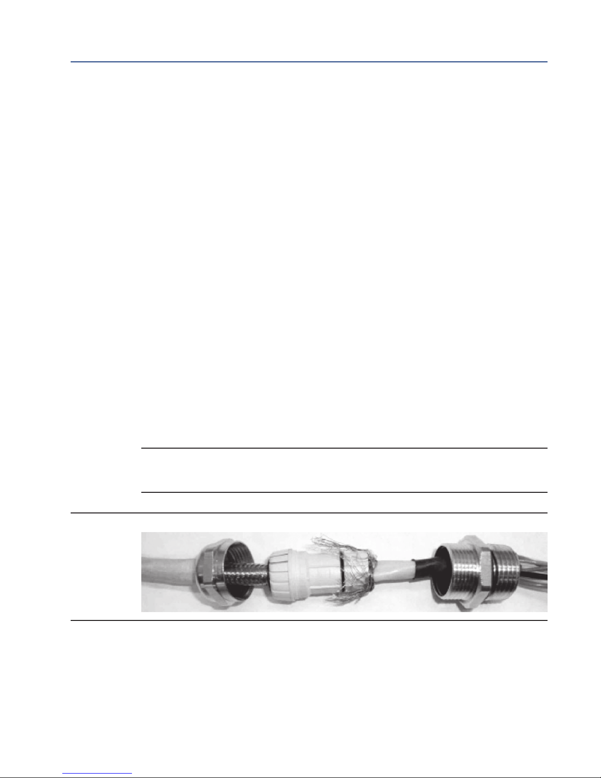
The Traditional Architecture cable is provided at the specified length and is ready for installation. The cable glands must be properly terminated to maintain EMC/EMI noise protection.
FIGURE 2-4. Traditional Architecture Cable Gland Assembly
Run the 7-conductor cable between the traditional architecture probe and the installation site for 6888Xi. Use1
new cable conduit or trough as needed.
Install the cable and lead wires to the probe per manufacturer’s instructions.2
Install the cable at the probe housing and at the 6888Xi enclosure according to the following procedure:3
a. Unscrew locking nut from gland assembly, Figure 2-4, and slide locking nut back along cable.
b. Pull the gland body away from the plastic insert. Use care not to damage the cable shield braid.
c. Insert the cable wires into the proper entry port in either the probe housing or the 6888Xi enclosure.
d. At the probe housing, apply Teflon tape or similar sealing compound to the tapered pipe threads.
Thread the gland body into the probe housing until properly seated.
16 Installation

Reference Manual Section 2: Installation
00809-0100-4892 January 2019
e. At the 6888Xi enclosure, insert the gland body into the left front cable port from the inside of the enclo-
sure. Use the rubber O-ring provided to seal the cable port.
. Ensure the cable shield braid is evenly formed over the gray insert. When properly formed, the braid
f
should be evenly spaced around the circumference of the insert and not extend beyond the narrow
diameter portion.
g. Carefully press the gray insert into the gland body. The grooves on the insert should align with similar
grooves inside the gland body. Press the insert in until it bottoms out in the gland body.
h. Slide the locking nut up and thread it onto the gland body. Tighten the locking nut so the rubber grom-
met inside the plastic insert compresses against the cable wall to provide an environmental seal.
At the 6888Xi, connect the cable leads to the connectors on the transmitter I/O board as indicated in Figure 2-7.4
Installation 17
Section 2: Installation Reference Manual
6
8
8
8
S
TA
NDA
RD P
RO
B
E
HO
US
ING
6
8
8
8
S
T
A
NDA
R
D
P
ROB
E
HOUS
IN
G
January 2019 00809-0100-4892
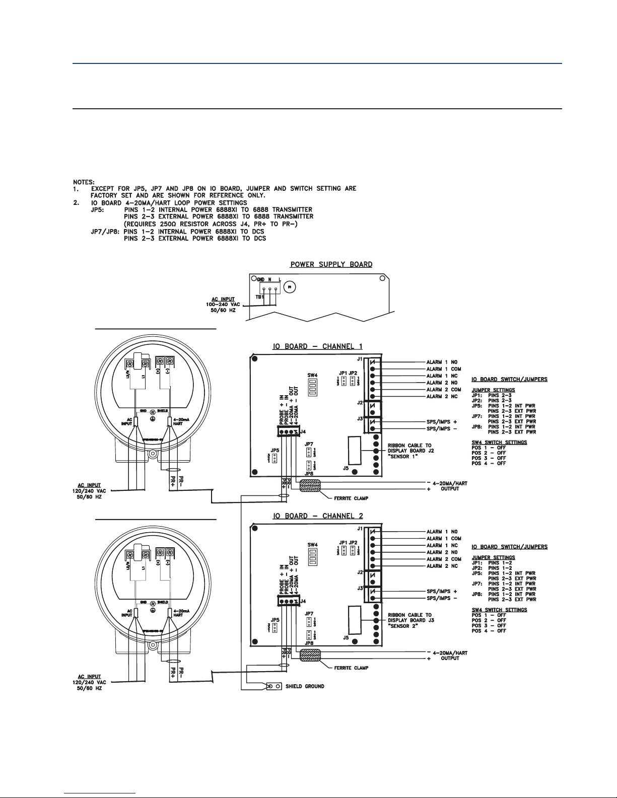
IGURE 2-5. Single/Dual Channel Wiring Diagram
F
18 Installation

Reference Manual Section 2: Installation
CHANNEL #2
CHANNEL #1
CHANNEL #2
CHANNEL #2
CHANNEL #1
CHANNEL #1
00809-0100-4892 January 2019
IGURE 2-5 cont. Single/Dual Channel Wiring Diagram
F
Installation 19
Section 2: Installation Reference Manual
5
1
-
6
8
8
8
X
i
6888 ST
AN
D
AR
D
PR
O
BE H
O
U
S
IN
G
January 2019 00809-0100-4892
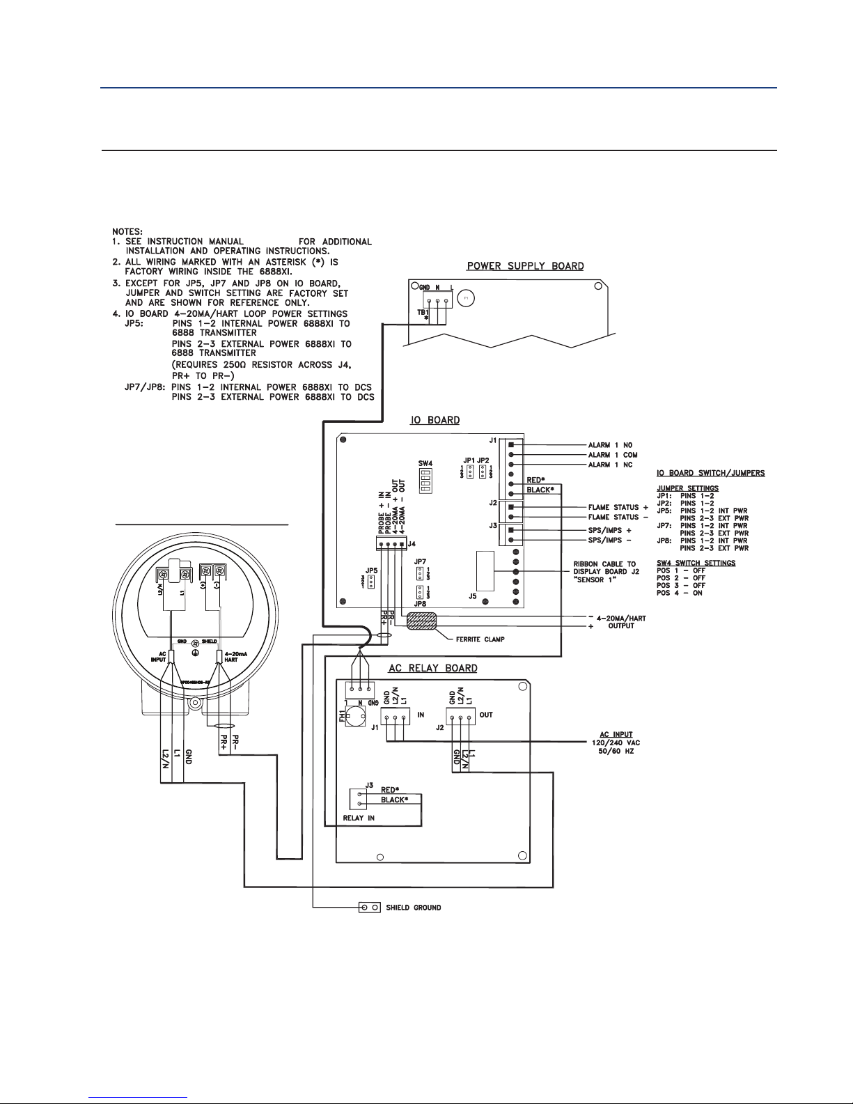
FIGURE 2-6. Single Channel with Flame Safety Wiring Diagram
20 Installation

Reference Manual Section 2: Installation
LOSS OF
FLAM
E OUTPUT TO B
URNER MANA
GEM
EN
T
SY
ST
EM
00809-0100-4892 January 2019
FIGURE 2-6 cont. Single Channel with Flame Safety Wiring Diagram
Installation 21

Section 2: Installation Reference Manual
January 2019 00809-0100-4892
FIGURE 2-7. Traditional Architecture Wiring Diagram
22 Installation
 Loading...