

Rosemount 644 Operating Manual

Reference Manual
00809-0200-4728, Rev SA
Rosemount™ 644 Temperature Transmitter
with HART® Protocol
July 2018


Reference Manual
00809-0200-4728, Rev SA
Contents
1Section 1: Introduction
2Section 2: Configuration
Contents
July 2018
1.1 Using this manual. . . . . . . . . . . . . . . . . . . . . . . . . . . . . . . . . . . . . . . . . . . . . . . . . . . . . . . . . . . . . . . . 1
1.1.1 Transmitter overview. . . . . . . . . . . . . . . . . . . . . . . . . . . . . . . . . . . . . . . . . . . . . . . . . . . . . . . 2
2.1 Overview . . . . . . . . . . . . . . . . . . . . . . . . . . . . . . . . . . . . . . . . . . . . . . . . . . . . . . . . . . . . . . . . . . . . . . . 3
2.2 Safety messages. . . . . . . . . . . . . . . . . . . . . . . . . . . . . . . . . . . . . . . . . . . . . . . . . . . . . . . . . . . . . . . . . 4
2.3 System readiness . . . . . . . . . . . . . . . . . . . . . . . . . . . . . . . . . . . . . . . . . . . . . . . . . . . . . . . . . . . . . . . . 4
2.3.1 Confirm correct device driver. . . . . . . . . . . . . . . . . . . . . . . . . . . . . . . . . . . . . . . . . . . . . . . . 5
2.3.2 Surges/transients . . . . . . . . . . . . . . . . . . . . . . . . . . . . . . . . . . . . . . . . . . . . . . . . . . . . . . . . . . 5
2.4 Configuration methods . . . . . . . . . . . . . . . . . . . . . . . . . . . . . . . . . . . . . . . . . . . . . . . . . . . . . . . . . . 5
2.4.1 Configuring on the bench . . . . . . . . . . . . . . . . . . . . . . . . . . . . . . . . . . . . . . . . . . . . . . . . . . . 5
2.4.2 Selecting a configuration tool . . . . . . . . . . . . . . . . . . . . . . . . . . . . . . . . . . . . . . . . . . . . . . . 6
2.4.3 Setting the loop to manual . . . . . . . . . . . . . . . . . . . . . . . . . . . . . . . . . . . . . . . . . . . . . . . . . . 8
2.4.4 Failure mode . . . . . . . . . . . . . . . . . . . . . . . . . . . . . . . . . . . . . . . . . . . . . . . . . . . . . . . . . . . . . . 9
2.4.5 HART software lock . . . . . . . . . . . . . . . . . . . . . . . . . . . . . . . . . . . . . . . . . . . . . . . . . . . . . . . . 9
2.5 Verify configuration. . . . . . . . . . . . . . . . . . . . . . . . . . . . . . . . . . . . . . . . . . . . . . . . . . . . . . . . . . . . . . 9
2.5.1 Field Communicator . . . . . . . . . . . . . . . . . . . . . . . . . . . . . . . . . . . . . . . . . . . . . . . . . . . . . . . 9
2.5.2 AMS Device Manager. . . . . . . . . . . . . . . . . . . . . . . . . . . . . . . . . . . . . . . . . . . . . . . . . . . . . . 10
2.5.3 LOI . . . . . . . . . . . . . . . . . . . . . . . . . . . . . . . . . . . . . . . . . . . . . . . . . . . . . . . . . . . . . . . . . . . . . . 10
2.5.4 Checking transmitter output . . . . . . . . . . . . . . . . . . . . . . . . . . . . . . . . . . . . . . . . . . . . . . . 10
2.6 Basic configuration of the transmitter . . . . . . . . . . . . . . . . . . . . . . . . . . . . . . . . . . . . . . . . . . . . . 12
2.6.1 Mapping the HART variables . . . . . . . . . . . . . . . . . . . . . . . . . . . . . . . . . . . . . . . . . . . . . . . 12
2.6.2 Configuring the sensor(s) . . . . . . . . . . . . . . . . . . . . . . . . . . . . . . . . . . . . . . . . . . . . . . . . . . 13
2.6.3 Setting output units. . . . . . . . . . . . . . . . . . . . . . . . . . . . . . . . . . . . . . . . . . . . . . . . . . . . . . . 14
2.7 Configure dual sensor options. . . . . . . . . . . . . . . . . . . . . . . . . . . . . . . . . . . . . . . . . . . . . . . . . . . . 15
2.7.1 Differential temperature configuration . . . . . . . . . . . . . . . . . . . . . . . . . . . . . . . . . . . . . . 16
2.7.2 Average temperature configuration . . . . . . . . . . . . . . . . . . . . . . . . . . . . . . . . . . . . . . . . . 17
2.7.3 Hot Backup configuration. . . . . . . . . . . . . . . . . . . . . . . . . . . . . . . . . . . . . . . . . . . . . . . . . . 18
2.7.4 Sensor drift alert configuration . . . . . . . . . . . . . . . . . . . . . . . . . . . . . . . . . . . . . . . . . . . . . 20
2.8 Configure device outputs. . . . . . . . . . . . . . . . . . . . . . . . . . . . . . . . . . . . . . . . . . . . . . . . . . . . . . . . 21
2.8.1 Re-range the transmitter. . . . . . . . . . . . . . . . . . . . . . . . . . . . . . . . . . . . . . . . . . . . . . . . . . . 21
2.8.2 Damping . . . . . . . . . . . . . . . . . . . . . . . . . . . . . . . . . . . . . . . . . . . . . . . . . . . . . . . . . . . . . . . . 22
Contents
2.8.3 Configure alarm and saturation levels . . . . . . . . . . . . . . . . . . . . . . . . . . . . . . . . . . . . . . . 24
2.8.4 Configuring the LCD display . . . . . . . . . . . . . . . . . . . . . . . . . . . . . . . . . . . . . . . . . . . . . . . . 25
2.9 Inputting device information. . . . . . . . . . . . . . . . . . . . . . . . . . . . . . . . . . . . . . . . . . . . . . . . . . . . . 27
i

Contents
July 2018
Reference Manual
00809-0200-4728, Rev SA
2.9.1 Tag, date, descriptor and message . . . . . . . . . . . . . . . . . . . . . . . . . . . . . . . . . . . . . . . . . . 27
2.10 Configure measurement filtering . . . . . . . . . . . . . . . . . . . . . . . . . . . . . . . . . . . . . . . . . . . . . . . . . 28
2.10.1 50/60 Hz filter . . . . . . . . . . . . . . . . . . . . . . . . . . . . . . . . . . . . . . . . . . . . . . . . . . . . . . . . . . . . 28
2.10.2 Resetting the device . . . . . . . . . . . . . . . . . . . . . . . . . . . . . . . . . . . . . . . . . . . . . . . . . . . . . . 29
2.10.3 Intermittent sensor detection . . . . . . . . . . . . . . . . . . . . . . . . . . . . . . . . . . . . . . . . . . . . . . 29
2.10.4 Open sensor hold off . . . . . . . . . . . . . . . . . . . . . . . . . . . . . . . . . . . . . . . . . . . . . . . . . . . . . . 30
2.11 Diagnostics and service. . . . . . . . . . . . . . . . . . . . . . . . . . . . . . . . . . . . . . . . . . . . . . . . . . . . . . . . . . 31
2.11.1 Performing a loop test . . . . . . . . . . . . . . . . . . . . . . . . . . . . . . . . . . . . . . . . . . . . . . . . . . . . . 31
2.11.2 Simulate digital signal (digital loop test) . . . . . . . . . . . . . . . . . . . . . . . . . . . . . . . . . . . . . 31
2.11.3 Thermocouple degradation diagnostic . . . . . . . . . . . . . . . . . . . . . . . . . . . . . . . . . . . . . . 32
2.11.4 Minimum/maximum tracking diagnostic . . . . . . . . . . . . . . . . . . . . . . . . . . . . . . . . . . . . 34
2.12 Establishing multi drop communication . . . . . . . . . . . . . . . . . . . . . . . . . . . . . . . . . . . . . . . . . . . 35
2.12.1 Changing a transmitter address. . . . . . . . . . . . . . . . . . . . . . . . . . . . . . . . . . . . . . . . . . . . . 35
2.13 Using the transmitter with the HART Tri-Loop . . . . . . . . . . . . . . . . . . . . . . . . . . . . . . . . . . . . . . 36
2.13.1 Set the transmitter to burst mode. . . . . . . . . . . . . . . . . . . . . . . . . . . . . . . . . . . . . . . . . . . 36
2.13.2 Set process variable output order . . . . . . . . . . . . . . . . . . . . . . . . . . . . . . . . . . . . . . . . . . . 37
2.14 Transmitter security . . . . . . . . . . . . . . . . . . . . . . . . . . . . . . . . . . . . . . . . . . . . . . . . . . . . . . . . . . . . 38
2.14.1 Available security options. . . . . . . . . . . . . . . . . . . . . . . . . . . . . . . . . . . . . . . . . . . . . . . . . . 38
3Section 3: Hardware Installation
3.1 Overview . . . . . . . . . . . . . . . . . . . . . . . . . . . . . . . . . . . . . . . . . . . . . . . . . . . . . . . . . . . . . . . . . . . . . . 41
3.2 Safety messages. . . . . . . . . . . . . . . . . . . . . . . . . . . . . . . . . . . . . . . . . . . . . . . . . . . . . . . . . . . . . . . . 42
3.3 Considerations . . . . . . . . . . . . . . . . . . . . . . . . . . . . . . . . . . . . . . . . . . . . . . . . . . . . . . . . . . . . . . . . . 42
3.3.1 General . . . . . . . . . . . . . . . . . . . . . . . . . . . . . . . . . . . . . . . . . . . . . . . . . . . . . . . . . . . . . . . . . . 42
3.3.2 Commissioning . . . . . . . . . . . . . . . . . . . . . . . . . . . . . . . . . . . . . . . . . . . . . . . . . . . . . . . . . . . 42
3.3.3 Installation . . . . . . . . . . . . . . . . . . . . . . . . . . . . . . . . . . . . . . . . . . . . . . . . . . . . . . . . . . . . . . . 42
3.3.4 Mechanical . . . . . . . . . . . . . . . . . . . . . . . . . . . . . . . . . . . . . . . . . . . . . . . . . . . . . . . . . . . . . . . 43
3.3.5 Electrical . . . . . . . . . . . . . . . . . . . . . . . . . . . . . . . . . . . . . . . . . . . . . . . . . . . . . . . . . . . . . . . . . 43
3.3.6 Environmental. . . . . . . . . . . . . . . . . . . . . . . . . . . . . . . . . . . . . . . . . . . . . . . . . . . . . . . . . . . . 43
3.4 Installation procedures . . . . . . . . . . . . . . . . . . . . . . . . . . . . . . . . . . . . . . . . . . . . . . . . . . . . . . . . . . 44
3.4.1 Set the alarm switch. . . . . . . . . . . . . . . . . . . . . . . . . . . . . . . . . . . . . . . . . . . . . . . . . . . . . . . 45
3.4.2 Mount the transmitter. . . . . . . . . . . . . . . . . . . . . . . . . . . . . . . . . . . . . . . . . . . . . . . . . . . . . 46
3.4.3 Install the device . . . . . . . . . . . . . . . . . . . . . . . . . . . . . . . . . . . . . . . . . . . . . . . . . . . . . . . . . . 47
3.4.4 Multichannel installations. . . . . . . . . . . . . . . . . . . . . . . . . . . . . . . . . . . . . . . . . . . . . . . . . . 51
3.4.5 LCD display installation . . . . . . . . . . . . . . . . . . . . . . . . . . . . . . . . . . . . . . . . . . . . . . . . . . . . 52
ii
Contents

Reference Manual
00809-0200-4728, Rev SA
4Section 4: Electrical Installation
5Section 5: Operation and Maintenance
Contents
July 2018
4.1 Overview . . . . . . . . . . . . . . . . . . . . . . . . . . . . . . . . . . . . . . . . . . . . . . . . . . . . . . . . . . . . . . . . . . . . . . 55
4.2 Safety messages. . . . . . . . . . . . . . . . . . . . . . . . . . . . . . . . . . . . . . . . . . . . . . . . . . . . . . . . . . . . . . . . 55
4.3 Wiring and powering the transmitter . . . . . . . . . . . . . . . . . . . . . . . . . . . . . . . . . . . . . . . . . . . . . 55
4.3.1 Sensor connections . . . . . . . . . . . . . . . . . . . . . . . . . . . . . . . . . . . . . . . . . . . . . . . . . . . . . . . 56
4.3.2 Power the transmitter . . . . . . . . . . . . . . . . . . . . . . . . . . . . . . . . . . . . . . . . . . . . . . . . . . . . . 58
4.3.3 Ground the transmitter . . . . . . . . . . . . . . . . . . . . . . . . . . . . . . . . . . . . . . . . . . . . . . . . . . . . 59
4.3.4 Wiring with a Rosemount 333 HART Tri-Loop (HART/4–20 mA only) . . . . . . . . . . . . 62
5.1 Overview . . . . . . . . . . . . . . . . . . . . . . . . . . . . . . . . . . . . . . . . . . . . . . . . . . . . . . . . . . . . . . . . . . . . . . 65
5.2 Safety messages. . . . . . . . . . . . . . . . . . . . . . . . . . . . . . . . . . . . . . . . . . . . . . . . . . . . . . . . . . . . . . . . 65
5.3 Calibration overview . . . . . . . . . . . . . . . . . . . . . . . . . . . . . . . . . . . . . . . . . . . . . . . . . . . . . . . . . . . . 66
5.3.1 Trimming . . . . . . . . . . . . . . . . . . . . . . . . . . . . . . . . . . . . . . . . . . . . . . . . . . . . . . . . . . . . . . . . 66
5.4 Sensor input trim . . . . . . . . . . . . . . . . . . . . . . . . . . . . . . . . . . . . . . . . . . . . . . . . . . . . . . . . . . . . . . . 66
5.4.1 Application: Linear offset (single-point trim solution). . . . . . . . . . . . . . . . . . . . . . . . . . 67
5.4.2 Application: Linear offset and slope correction (two-point trim) . . . . . . . . . . . . . . . . 67
5.4.3 Recall factory trim—sensor trim. . . . . . . . . . . . . . . . . . . . . . . . . . . . . . . . . . . . . . . . . . . . . 68
5.4.4 Active calibrator and EMF compensation. . . . . . . . . . . . . . . . . . . . . . . . . . . . . . . . . . . . . 69
5.5 Trim the analog output. . . . . . . . . . . . . . . . . . . . . . . . . . . . . . . . . . . . . . . . . . . . . . . . . . . . . . . . . . 69
5.5.1 Analog output trim or scaled analog output trim. . . . . . . . . . . . . . . . . . . . . . . . . . . . . . 69
5.5.2 Analog output trim. . . . . . . . . . . . . . . . . . . . . . . . . . . . . . . . . . . . . . . . . . . . . . . . . . . . . . . . 70
5.5.3 Performing a scaled output trim . . . . . . . . . . . . . . . . . . . . . . . . . . . . . . . . . . . . . . . . . . . . 71
5.6 Transmitter-sensor matching . . . . . . . . . . . . . . . . . . . . . . . . . . . . . . . . . . . . . . . . . . . . . . . . . . . . 71
5.7 Switching HART Revision . . . . . . . . . . . . . . . . . . . . . . . . . . . . . . . . . . . . . . . . . . . . . . . . . . . . . . . . 73
5.7.1 Generic menu . . . . . . . . . . . . . . . . . . . . . . . . . . . . . . . . . . . . . . . . . . . . . . . . . . . . . . . . . . . . 73
5.7.2 Field Communicator . . . . . . . . . . . . . . . . . . . . . . . . . . . . . . . . . . . . . . . . . . . . . . . . . . . . . . 73
5.7.3 AMS Device Manager. . . . . . . . . . . . . . . . . . . . . . . . . . . . . . . . . . . . . . . . . . . . . . . . . . . . . . 73
5.7.4 LOI . . . . . . . . . . . . . . . . . . . . . . . . . . . . . . . . . . . . . . . . . . . . . . . . . . . . . . . . . . . . . . . . . . . . . . 74
6Section 6: Troubleshooting
6.1 Overview . . . . . . . . . . . . . . . . . . . . . . . . . . . . . . . . . . . . . . . . . . . . . . . . . . . . . . . . . . . . . . . . . . . . . . 75
6.2 Safety messages. . . . . . . . . . . . . . . . . . . . . . . . . . . . . . . . . . . . . . . . . . . . . . . . . . . . . . . . . . . . . . . . 75
6.3 4-20 mA/HART output . . . . . . . . . . . . . . . . . . . . . . . . . . . . . . . . . . . . . . . . . . . . . . . . . . . . . . . . . . 76
6.4 Diagnostic messages. . . . . . . . . . . . . . . . . . . . . . . . . . . . . . . . . . . . . . . . . . . . . . . . . . . . . . . . . . . . 77
6.4.1 Failed status . . . . . . . . . . . . . . . . . . . . . . . . . . . . . . . . . . . . . . . . . . . . . . . . . . . . . . . . . . . . . . 77
Contents
6.4.2 Warning status . . . . . . . . . . . . . . . . . . . . . . . . . . . . . . . . . . . . . . . . . . . . . . . . . . . . . . . . . . . 78
6.4.3 Other LCD display messages . . . . . . . . . . . . . . . . . . . . . . . . . . . . . . . . . . . . . . . . . . . . . . . 80
iii

Contents
July 2018
Reference Manual
00809-0200-4728, Rev SA
6.5 Return of materials . . . . . . . . . . . . . . . . . . . . . . . . . . . . . . . . . . . . . . . . . . . . . . . . . . . . . . . . . . . . . 80
7Section 7: Safety Instrumented Systems (SIS) Certification
7.1 SIS certification. . . . . . . . . . . . . . . . . . . . . . . . . . . . . . . . . . . . . . . . . . . . . . . . . . . . . . . . . . . . . . . . . 81
7.2 Safety certified identification. . . . . . . . . . . . . . . . . . . . . . . . . . . . . . . . . . . . . . . . . . . . . . . . . . . . . 81
7.3 Installation. . . . . . . . . . . . . . . . . . . . . . . . . . . . . . . . . . . . . . . . . . . . . . . . . . . . . . . . . . . . . . . . . . . . . 82
7.4 Configuration . . . . . . . . . . . . . . . . . . . . . . . . . . . . . . . . . . . . . . . . . . . . . . . . . . . . . . . . . . . . . . . . . . 82
7.4.1 Damping . . . . . . . . . . . . . . . . . . . . . . . . . . . . . . . . . . . . . . . . . . . . . . . . . . . . . . . . . . . . . . . . 82
7.4.2 Alarm and saturation levels . . . . . . . . . . . . . . . . . . . . . . . . . . . . . . . . . . . . . . . . . . . . . . . . 82
7.5 Operation and maintenance . . . . . . . . . . . . . . . . . . . . . . . . . . . . . . . . . . . . . . . . . . . . . . . . . . . . . 83
7.5.1 Proof test . . . . . . . . . . . . . . . . . . . . . . . . . . . . . . . . . . . . . . . . . . . . . . . . . . . . . . . . . . . . . . . . 83
7.5.2 Partial proof test 1 . . . . . . . . . . . . . . . . . . . . . . . . . . . . . . . . . . . . . . . . . . . . . . . . . . . . . . . . 83
7.5.3 Comprehensive proof test 2 . . . . . . . . . . . . . . . . . . . . . . . . . . . . . . . . . . . . . . . . . . . . . . . . 84
7.5.4 Comprehensive proof test 3 . . . . . . . . . . . . . . . . . . . . . . . . . . . . . . . . . . . . . . . . . . . . . . . . 84
7.5.5 Inspection . . . . . . . . . . . . . . . . . . . . . . . . . . . . . . . . . . . . . . . . . . . . . . . . . . . . . . . . . . . . . . . 85
7.6 Specifications . . . . . . . . . . . . . . . . . . . . . . . . . . . . . . . . . . . . . . . . . . . . . . . . . . . . . . . . . . . . . . . . . . 85
7.6.1 Failure rate data . . . . . . . . . . . . . . . . . . . . . . . . . . . . . . . . . . . . . . . . . . . . . . . . . . . . . . . . . . 85
7.6.2 Failure values . . . . . . . . . . . . . . . . . . . . . . . . . . . . . . . . . . . . . . . . . . . . . . . . . . . . . . . . . . . . . 85
7.6.3 Product life. . . . . . . . . . . . . . . . . . . . . . . . . . . . . . . . . . . . . . . . . . . . . . . . . . . . . . . . . . . . . . . 85
AAppendix A: Reference Data
A.1 Product Certifications . . . . . . . . . . . . . . . . . . . . . . . . . . . . . . . . . . . . . . . . . . . . . . . . . . . . . . . . . . . 87
A.2 Ordering Information, Specifications, and Drawings . . . . . . . . . . . . . . . . . . . . . . . . . . . . . . . . 87
BAppendix B: Field Communicator Menu Trees and Fast Keys
B.1 Field Communicator menu trees . . . . . . . . . . . . . . . . . . . . . . . . . . . . . . . . . . . . . . . . . . . . . . . . . 89
B.2 Field Communicator Fast Keys . . . . . . . . . . . . . . . . . . . . . . . . . . . . . . . . . . . . . . . . . . . . . . . . . . . 95
CAppendix C: Local Operator Interface (LOI)
C.1 Number entry . . . . . . . . . . . . . . . . . . . . . . . . . . . . . . . . . . . . . . . . . . . . . . . . . . . . . . . . . . . . . . . . . . 97
C.2 Text entry . . . . . . . . . . . . . . . . . . . . . . . . . . . . . . . . . . . . . . . . . . . . . . . . . . . . . . . . . . . . . . . . . . . . . 98
C.2.1 Scrolling . . . . . . . . . . . . . . . . . . . . . . . . . . . . . . . . . . . . . . . . . . . . . . . . . . . . . . . . . . . . . . . . . 98
C.3 Timeout . . . . . . . . . . . . . . . . . . . . . . . . . . . . . . . . . . . . . . . . . . . . . . . . . . . . . . . . . . . . . . . . . . . . . . 100
C.4 Saving and canceling. . . . . . . . . . . . . . . . . . . . . . . . . . . . . . . . . . . . . . . . . . . . . . . . . . . . . . . . . . . 100
C.5 LOI menu tree. . . . . . . . . . . . . . . . . . . . . . . . . . . . . . . . . . . . . . . . . . . . . . . . . . . . . . . . . . . . . . . . . 101
C.6 LOI menu tree – extended menu . . . . . . . . . . . . . . . . . . . . . . . . . . . . . . . . . . . . . . . . . . . . . . . . 102
iv
Contents
Reference Manual
00809-0200-4728, Rev SA
Rosemount™ 644 Temperature
Transmitter
Rosemount 644 Hardware Revision 31 2 2
Device Revision 7 8 9
HART
Read this manual before working with the product. For personal and system safety, and for optimum
product performance, make sure to thoroughly understand the contents before installing, using, or
maintaining this product.
The United States has two toll-free assistance numbers and one international number.
Customer Central
1-800-999-9307 (7:00 a.m. to 7:00 p.m. CST)
National Response Center
1-800-654-7768 (24 hours a day)
Equipment service needs
International
1-(952)-906-8888
The products described in this document are NOT designed for nuclear-qualified applications.
Using non-nuclear qualified products in applications that require nuclear-qualified hardware or
products may cause inaccurate readings.
For information on Rosemount nuclear-qualified products, contact a Emerson
Railmount Headmount Headmount
®
Revision 5 5 7
™
Sales Representative.
Title Page
July 2018
Title Page
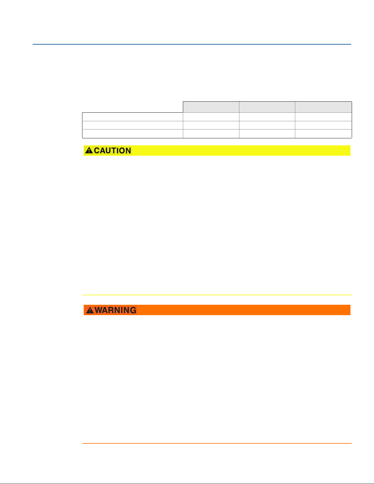
Failure to follow these installation guidelines could result in death or serious injury.
Make sure only qualified personnel perform the installation.
Explosions could result in death or serious injury.
Do not remove the connection head cover in explosive atmospheres when the circuit is live.
Before connecting HART in an explosive atmosphere, make sure the instruments in the loop
are installed in accordance with intrinsically safe or non-incendive field wiring practices.
Verify the operating atmosphere of the transmitter is consistent with the appropriate
hazardous locations certifications.
All connection head covers must be fully engaged to meet explosion-proof requirements.
Process leaks could result in death or serious injury.
Do not remove the thermowell while in operation.
Install and tighten thermowells and sensors before applying pressure.
Electrical shock could cause death or serious injury.
Use extreme caution when making contact with the leads and terminals.
v

Title Page
July 2018
Reference Manual
00809-0200-4728, Rev SA
vi
Title Page

Reference Manual
00809-0200-4728 Rev SA
Section 1 Introduction
1.1 Using this manual
This manual is designed to assist in the installation, operation, and maintenance of Rosemount™ 644
Head Mount, Field Mount, and Rail Mount Transmitters with the HART
Section 2: Configuration provides instruction the commissioning and operating the Rosemount 644
HART Transmitter. The information explains how to configure software functions and many
configuration parameters on an Asset Management System, a Field Communicator, and the Local
Operator Interface display option.
Section 3: Hardware Installation contains mechanical installation instructions for the transmitter.
Section 4: Electrical Installation contains electrical installation instructions and considerations for the
transmitter.
Section 5: Operation and Maintenance contains common operation and maintenance techniques for the
transmitter.
®
protocol.
Introduction
July 2018
Section 6: Troubleshooting provides troubleshooting techniques for the most common transmitter
operating problems.
Section 7: Safety Instrumented Systems (SIS) Certification provides identification, installation,
configuration, operation and maintenance, and inspection information for Safety Instrumented Systems
as it pertains to the Rosemount 644 Head Mount and Field Mount Temperature Transmitter.
Appendix A: Reference Data supplies procedure on how to get the specifications, ordering information,
and product certification.
Appendix B: Field Communicator Menu Trees and Fast Keys contains Field Communicator menu trees
and Field Communicator Fast Keys.
Appendix C: Local Operator Interface (LOI) contains instructions for number entry, text entry, as well as
the LOI menu tree and LOI extended menu tree.
Introduction
1

Introduction
July 2018
1.1.1 Transmitter overview
The Rosemount 644 Head Mount and Field Mount Temperature Transmitters support the following
features:
HART configuration with Selectable HART revision capability (Revisions 5 or 7)
Accepts either 1 or 2 inputs from a wide variety of sensor types (2-, 3-, and 4-wire RTD, thermocouple,
mV and Ohm)
A compact transmitter size with electronics completely encapsulated in protective silicone and
enclosed in a plastic housing ensuring long-term transmitter reliability
Optional Safety Certification Option (IEC 61508 SIL 2)
Optional enhanced accuracy and stability performance
Optional LCD display with extended temperature ratings of –40 to 85 °C
Optional advanced LCD display with local operator interface (LOI)
The Rosemount 644 Head Mount Transmitter is available in two housing materials (Aluminum and
SST) and various housing options that allow for mounting flexibility in a variety of environmental
conditions. The Rosemount 644 Field Mount is available in an aluminum housing.
Special dual-sensor features include Hot Backup
average temperature measurements, and four simultaneous measurement variable outputs in
addition to the analog output signal.
Reference Manual
00809-0200-4728 Rev SA
™
, Sensor Drift Alert, first good, differential and
Additional advanced features include: Thermocouple degradation diagnostic, which monitors
thermocouple health, and process and transmitter minimum/maximum temperature tracking.
The Rosemount 644 Rail Mount Temperature Transmitter supports the following features:
4–20 mA/HART protocol (Revision 5)
Accepts one sensor input from a wide variety of sensor types (2-, 3-, and 4-wire RTD, Thermocouple,
mV and Ohm)
Completely encapsulated electronics to ensure long term transmitter reliability
Refer to the following literature for a full range of compatible connection heads, sensors, and
thermowells provided by Emerson.
Rosemount Volume 1 Temperature Sensors and Accessories (English) Product Data Sheet
Rosemount DIN-Style Temperature Sensors and Thermowells (Metric) Product Data Sheet
2
Introduction

Reference Manual
00809-0200-4728, Rev SA
Section 2 Configuration
Overview . . . . . . . . . . . . . . . . . . . . . . . . . . . . . . . . . . . . . . . . . . . . . . . . . . . . . . . . . . . . . . . . . . . . . . . . . . . . page 3
Safety messages . . . . . . . . . . . . . . . . . . . . . . . . . . . . . . . . . . . . . . . . . . . . . . . . . . . . . . . . . . . . . . . . . . . . . . page 4
System readiness . . . . . . . . . . . . . . . . . . . . . . . . . . . . . . . . . . . . . . . . . . . . . . . . . . . . . . . . . . . . . . . . . . . . .page 4
Configuration methods . . . . . . . . . . . . . . . . . . . . . . . . . . . . . . . . . . . . . . . . . . . . . . . . . . . . . . . . . . . . . . . . page 5
Verify configuration . . . . . . . . . . . . . . . . . . . . . . . . . . . . . . . . . . . . . . . . . . . . . . . . . . . . . . . . . . . . . . . . . . . page 9
Basic configuration of the transmitter . . . . . . . . . . . . . . . . . . . . . . . . . . . . . . . . . . . . . . . . . . . . . . . . . . . page 11
Configure dual sensor options . . . . . . . . . . . . . . . . . . . . . . . . . . . . . . . . . . . . . . . . . . . . . . . . . . . . . . . . . . page 15
Configure device outputs . . . . . . . . . . . . . . . . . . . . . . . . . . . . . . . . . . . . . . . . . . . . . . . . . . . . . . . . . . . . . . page 20
Inputting device information . . . . . . . . . . . . . . . . . . . . . . . . . . . . . . . . . . . . . . . . . . . . . . . . . . . . . . . . . . . page 26
Configure measurement filtering . . . . . . . . . . . . . . . . . . . . . . . . . . . . . . . . . . . . . . . . . . . . . . . . . . . . . . . page 27
Diagnostics and service . . . . . . . . . . . . . . . . . . . . . . . . . . . . . . . . . . . . . . . . . . . . . . . . . . . . . . . . . . . . . . . . page 30
Establishing multi drop communication . . . . . . . . . . . . . . . . . . . . . . . . . . . . . . . . . . . . . . . . . . . . . . . . . page 34
Using the transmitter with the HART Tri-Loop . . . . . . . . . . . . . . . . . . . . . . . . . . . . . . . . . . . . . . . . . . . . page 35
Configuration
July 2018
2.1 Overview
This section contains information on commissioning and tasks that should be performed on the bench
prior to installation. Field Communicator, AMS Device Manager, and Local Operator Interface (LOI)
instructions are given to perform configuration functions. For convenience, Field Communicator Fast Key
sequences are labeled “Fast Keys,” and abbreviated LOI menus are provided for each function below. The
LOI is only available on the Rosemount
instructions referencing the interface will not apply to the Rail mount form factor.
Full Field Communicator menu trees and Fast Key sequences are available in Appendix B: Field
Communicator Menu Trees and Fast Keys. Local operator interface menu trees are available in
Appendix C: Local Operator Interface (LOI).
™
644 Head Mount and Field Mount designs, and the configuration
Config uration
3

Configuration
July 2018
2.2 Safety messages
Instructions and procedures in this section may require special precautions to ensure the safety of the
personnel performing the operations. Information that potentially raises safety issues is indicated by a
warning symbol ( ). Refer to the following safety messages before performing an operation preceded
by this symbol.
Failure to follow these installation guidelines could result in death or serious injury.
Make sure only qualified personnel perform the installation.
Explosions could result in death or serious injury.
Do not remove the connection head cover in explosive atmospheres when the circuit is live.
Before connecting a Field Communicator in an explosive atmosphere, make sure the instruments in
the loop are installed in accordance with intrinsically safe or non-incendive field wiring practices.
Verify the operating atmosphere of the transmitter is consistent with the appropriate hazardous
locations certifications.
All connection head covers must be fully engaged to meet explosion-proof requirements.
Process leaks could result in death or serious injury.
Do not remove the thermowell while in operation.
Install and tighten thermowells and sensors before applying pressure.
Electrical shock could cause death or serious injury.
Use extreme caution when making contact with the leads and terminals.
Reference Manual
00809-0200-4728, Rev SA
2.3 System readiness
Confirm HART® revision capability
If using HART based control or asset management systems, confirm the HART capability of those
systems prior to transmitter installation. Not all systems are capable of communicating with HART
Revision 7 protocol. This transmitter can be configured for either HART Revision 5 or 7.
For instructions on how to change the HART revision of your transmitter, see “System readiness” on
page 4.
2.3.1 Confirm correct device driver
Verify the latest Device Driver files are loaded on your systems to ensure proper communications.
Download the latest Device Driver at Emerson.com/Rosemount or Fieldcomm.org.
4
Configuration
Reference Manual
00809-0200-4728, Rev SA
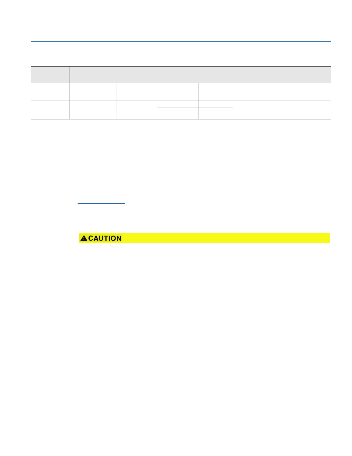
Table 2-1. Rosemount 644 Device Revisions and Files
Configuration
July 2018
Software date Identify device Find device driver files Review instructions
Date
June 2012 1.1.1 01
1. NAMUR Software Revision is located on the hardware tag of the device. HART Software Revision can be read using a HART Communication tool.
2. Device Driver file names use Device and DD Revision, e.g. 10_01. HART Protocol is designed to enable legacy device driver revisions to continue to communicate with
new HART devices. To access new functionality, the new Device Driver must be downloaded. It is recommended to download the new Device Dri ver files to ens ure full
functionality.
3. HART Revision 5 and 7 Selectable. Dual Sensor support, Safety Certified, Advanced Diagnostics (if ordered), Enhanced Accuracy and Stability (if ordered).
NAMUR Software
Revision
HART Software
Revision
HART Universal
Revision
(1)
5 8 Rosemount 644
7 9
Device
Revision
(2)
Document
Tem per atu re Transmitter
Reference Manual
Review
functionality
Changes to
Software
See Footnote 3
for list of changes
2.3.2 Surges/transients
The transmitter will withstand electrical transients of the energy level encountered in static discharges or
induced switching transients. However, high-energy transients, such as those induced in wiring from
nearby lightning strikes, welding, heavy electrical equipment, or switching gears, can damage both the
transmitter and the sensor. To protect against high-energy transients, install the transmitter into a
suitable connection head with the integral transient protector, option T1. Refer to the Rosemount 644
Product Data Sheet
for more information.
2.4 Configuration methods
(3)
Set all transmitter hardware adjustments during commissioning to avoid exposing the transmitter
electronics to the plant environment after installation.
The Rosemount 644 Transmitter can be configured either before or after installation. Configuring the
transmitter on the bench using either a Field Communicator, AMS Device Manager, or LOI ensures all
transmitter components are in working order prior to installation.
The Rosemount 644 Transmitter can be configured either on-line or off-line using a Field Communicator,
AMS Device Manager or the optional LOI (Head mount and field mount). During on-line configuration,
the transmitter is connected to a Field communicator. Data is entered in the working register of the
communicator and sent directly to the transmitter.
Off-line configuration consists of storing configuration data in a Field Communicator while it is not
connected to a transmitter. Data is stored in nonvolatile memory and can be downloaded to the
transmitter at a later time.
2.4.1 Configuring on the bench
To configure on the bench, required equipment includes a power supply, a digital multimeter (DMM),
and Field Communicator, AMS Device Manager, or a LOI – option M4.
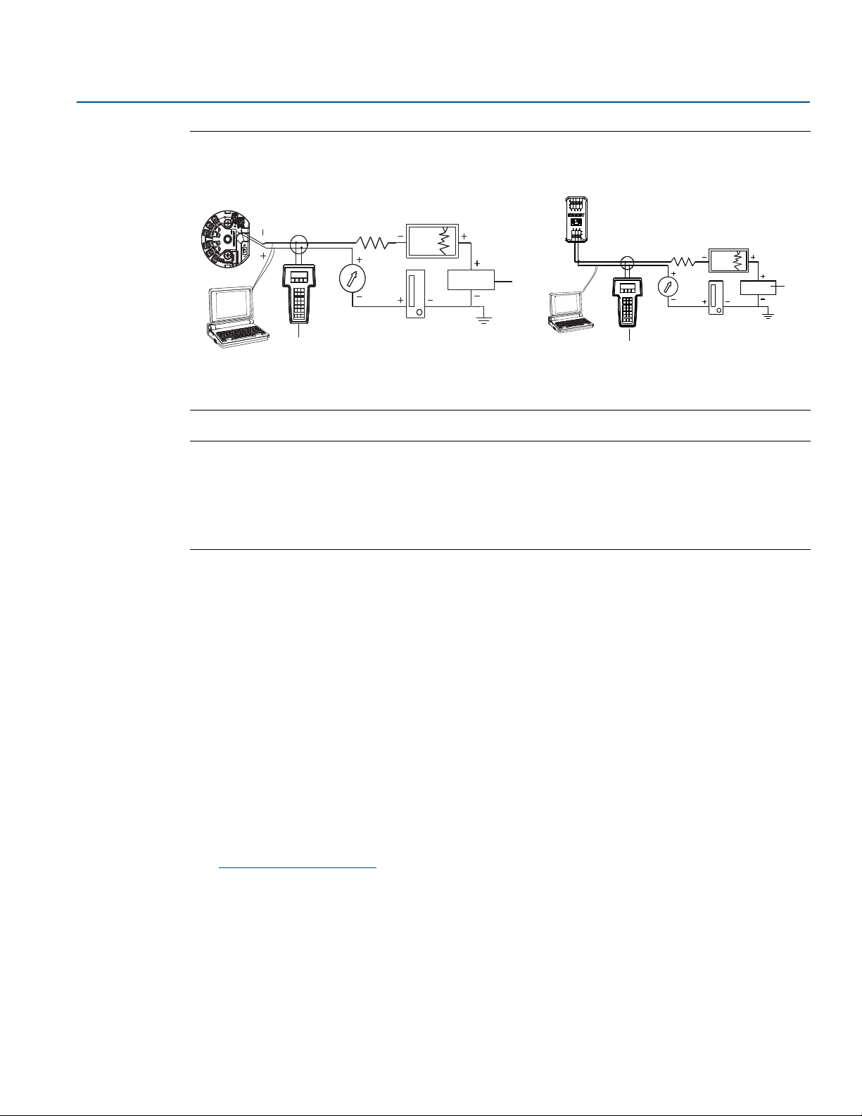
Connect the equipment as shown in Figure 2-1. Connect HART Communication leads at any termination
point in the signal loop. To ensure successful HART Communication, a resistance of at least 250 Ohms
must be present between the transmitter and the power supply. Connect the Field Communicator leads
to the clips behind the power (+,–) terminals on the top of the device. Avoid exposing the transmitter
electronics to the plant environment after installation by setting all transmitter jumpers during the
commissioning stage on the bench.
Config uration
5
Configuration
B
A
B
250 Ω ≤ R
L
≤ 1100 Ω
A
July 2018
Reference Manual
00809-0200-4728, Rev SA
Figure 2-1. Powering the Transmitter for Bench Configuration
Rosemount 644 Head Mount and Field Mount Rosemount 644 Rail Mount
A. Power supply
B. Field Communicator
Note
Signal loop may be grounded at any point or left ungrounded.
A Field Communicator may be connected at any termination point in the signal loop. The signal loop
must have between 250 and 1100 Ohms load for communications.
Max torque is 6 in-lb (0.7 N-m).
2.4.2 Selecting a configuration tool
Field Communicator
The Field Communicator is a hand-held device that exchanges information with the transmitter from the
control room, the instrument site, or any wiring termination point in the loop. To facilitate
communication, connect the Field Communicator, shown in this manual, in parallel with the transmitter
(see Figure 2-1). Use the loop connection ports on the rear panel of the Field Communicator. The
connections are non-polarized. Do not make connections to the serial port or the Ni-Cad recharger jack
in explosive atmospheres. Before connecting the Field Communicator in an explosive atmosphere make
sure the instruments in the loop are installed in accordance with intrinsically safe or non-incendive field
wiring practices.
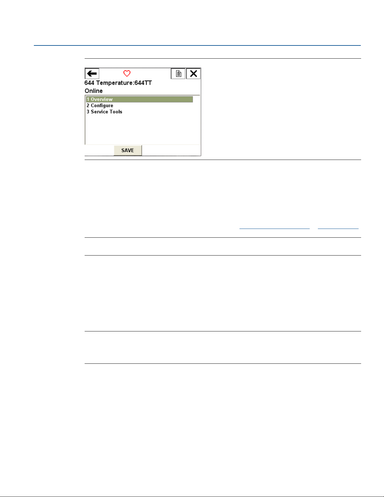
There are two interfaces available with the Field Communicator: Traditional and Dashboard interfaces.
All steps using a Field Communicator will be using Dashboard interfaces. Figure 2-2 shows the Device
Dashboard interface. As stated in “System readiness” on page 4, it is critical that the latest DD’s are
loaded into the Field Communicator for optimal transmitter performance.
Visit Emerson.com/Rosemount
Turn on the Field Communicator by pressing the ON/OFF key. The Field Communicator will search for a
HART-compatible device and indicate when the connection is made. If the Field Communicator fails to
connect, it indicates that no device was found. If this occurs, refer to Section 6: Troubleshooting.
to download latest DD library.
6
Configuration
Reference Manual
00809-0200-4728, Rev SA
Figure 2-2. Field Communicator Device Dashboard Interface
Field Communicator menu trees and Fast Keys are available in Appendix B: Field Communicator Menu
Trees and Fast Keys Configuring with AMS Device Manager.
With an AMS Device Manager software package, you can commission and configure instruments,
monitor status and alerts, troubleshoot from the control room, perform advanced diagnostics, manage
calibration, and automatically document activities with a single application.
Configuration
July 2018
Full configuration capability with AMS Device Manager requires loading the most current Device
Descriptor (DD) for this device. Download the latest DD at Emerson.com/Rosemount
Note
All steps listed in this product manual using AMS Device Manager assume the use of Version 11.5.
or Fieldcomm.org.
LOI
The LOI requires option code M4 to be ordered. To activate the LOI push either configuration button.
Configuration buttons are located on the LCD display (must remove housing cover to access the
interface. See Ta bl e 2 -2 for configuration button functionality and Figure 2-3 for configuration button
location. When using the LOI for configuration, several features require multiple screens for a successful
configuration. Data entered will be saved on a screen-by-screen basis; the LOI will indicate this by flashing
“SAVED” on the LCD display each time.
Note
Entering into the LOI menu effectively disables the ability to write to the device by any other host or
configuration tool. Make sure this is communicated to necessary personnel before using the LOI for
device configuration.
Config uration
7

Configuration
A
July 2018
Reference Manual
00809-0200-4728, Rev SA
Figure 2-3. LOI Configuration Buttons
A. Configuration buttons
Table 2-2. LOI Button Operation
Button
Left No SCROLL
Right Yes ENTER
LOI password
An LOI password can be entered and enabled to prevent review and modification of device configuration
via the LOI. This does not prevent configuration from HART or through the control system. The LOI
password is a four-digit code that is to be set by the user. If the password is lost or forgotten the master
password is “9307”. The LOI password can be configured and enabled/disabled by HART communication
via a Field Communicator, AMS Device Manager, or the LOI.
LOI menu trees are available in Appendix C: Local Operator Interface (LOI).
2.4.3 Setting the loop to manual
When sending or requesting data that would disrupt the loop or change the output of the transmitter,
set the process application loop to manual. The Field Communicator, AMS Device Manager or LOI will
prompt you to set the loop to manual when necessary. Acknowledging this prompt does not set the loop
to manual. The prompt is only a reminder; set the loop to manual as a separate operation.
2.4.4 Failure mode
As part of normal operation, each transmitter continuously monitors its own performance. This
automatic diagnostics routine is a timed series of checks repeated continuously. If diagnostics detect an
input sensor failure or a failure in the transmitter electronics, the transmitter drives its output to low or
high depending on the position of the failure mode switch. If the sensor temperature is outside the range
limits, the transmitter saturates its output to 3.9 mA for standard configuration on the low end (3.8 mA if
configured for NAMUR-compliant operation) and 20.5 mA on the high end (or NAMUR-compliant).
These values are also custom configurable by the factory or using the Field Communicator.The values to
which the transmitter drives its output in failure mode depend on whether it is configured to standard,
NAMUR-compliant, or custom operation. See Rosemount 644 Tempeture Transmitter Product Data
Sheet for standard and NAMUR-compliant operation parameters.
8
Configuration

Reference Manual
00809-0200-4728, Rev SA
2.4.5 HART software lock
The HART Software Lock prevents changes to the transmitter configuration from all sources; all changes
requested via HART by the Field Communicator, AMS Device manager or the LOI will be rejected. The
HART Lock can only be set via HART communication, and is only available in HART Revision 7 mode. The
HART Lock can be enabled or disabled with a Field Communicator or AMS Device Manager.
Field Communicator
From the HOME screen, enter the Fast Key sequence.
Configuration
July 2018
Device Dashboard Fast Keys
AMS Device Manager
1. Right click on the device and select Configure.
2. Under Manual Setup select the Security tab.
3. Select the Lock/Unlock button under HART Lock (Software) and follow the screen prompts.
2.5 Verify configuration
It is recommended that various configuration parameters are verified prior to installation into the
process. The various parameters are detailed out for each configuration tool. Depending on what
configuration tool(s) are available follow the steps listed relevant to each tool.
2.5.1 Field Communicator
Configuration parameters listed in Tabl e 2-3 below are the basic parameters that should be reviewed
prior to transmitter installation. A full list of configuration parameters that can be reviewed and
configured using a Field Communicator are located in Appendix B: Field Communicator Menu Trees and
Fast Keys. A Rosemount 644 Device Descriptor (DD) must be installed on the Field Communicator to
verify configuration.
1. Verify device configuration using Fast Key sequences in Tab le 2-3.
a. From the HOME screen, enter the Fast Key sequences listed in Tab le 2-3 .
Table 2-3. Device Dashboard Fast Key Sequences
3, 2, 1
Config uration
Function HART 5 HART 7
Alarm Values 2, 2, 5, 6 2, 2, 5, 6
Damping Values 2, 2, 1, 5 2, 2, 1, 6
Lower Range Value (LRV) 2, 2, 5, 5, 3 2, 2, 5, 5, 3
Upper Range Value (URV) 2, 2, 5, 5, 2 2, 2, 5, 5, 2
Primary Variable 2, 2, 5, 5, 1 2, 2, 5, 5, 1
Sensor 1 Configuration 2, 1, 1 2, 1, 1
Sensor 2 Configuration
Ta g 2, 2, 7, 1, 1 2, 2, 7, 1, 1
Units 2, 2, 1, 5 2, 2, 1, 4
1. Available only if option code (S) or (D) is ordered.
(1)
2, 1, 1 2, 1, 1
9

Configuration
July 2018
2.5.2 AMS Device Manager
1. Right click on the device and select Configuration Properties from the menu.
2. Navigate the tabs to review the transmitter configuration data.
2.5.3 LOI
Press any configuration button to activate the LOI. Select VIEW CONFIG to review the below parameters.
Use the configuration buttons to navigate through the menu. The parameters to be reviewed prior to
installation include:
Ta g
Sensor configuration
Units
Alarm and saturation levels
Primary variable
Range values
Damping
Reference Manual
00809-0200-4728, Rev SA
2.5.4 Checking transmitter output
Before performing other transmitter on-line operations, review the Rosemount 644 Transmitter digital
output parameters to ensure that the transmitter is operating properly and is configured to the
appropriate process variables.
Checking or setting process variables
The “Process Variables” menu displays process variables, including sensor temperature, percent of range,
analog output, and terminal temperature. These process variables are continuously updated. The default
primary variable is Sensor 1. The secondary variable is the transmitter terminal temperature by default.
Field Communicator
From the HOME screen, enter the Fast Key sequence.
Device Dashboard Fast Keys
AMS Device Manager
Right click on the device and select Service Tools from the menu. The Variables tab displays the following
process variables:
Primary, second, third and fourth variables, as well as the analog output.
LOI
To check the process variables from the LOI, the user must first configure the display to show the desired
variables (see “Configuring the LCD display” on page 25). Once the desired device variables are chosen,
simply EXIT the LOI menu and view the alternating values on the display screen.
3, 2, 1
10
Configuration

Reference Manual
ON/OFFVIEW CONFIG
ZERO TRIM
UNITS
RERANGE
LOOP TEST
DISPLAY
DISPLAY
EXTENDED MENU
EXIT MENU
SENSOR 1
SENSOR 2*
ANALOG
PV
AVG
1ST GOOD
DIFF
% RANGE
TERM
MNMAX1*
MNMAX2*
MNMAX3*
MNMAX4*
BACK TO MENU
EXIT MENU
00809-0200-4728, Rev SA
Configuration
July 2018
2.6 Basic configuration of the transmitter
2.6.1 Mapping the HART variables
Config uration
The Rosemount 644 Transmitter must be configured for certain basic variables in order to be
operational. In many cases, all of these variables are pre-configured at the factory. Configuration may be
required if the transmitter is not configured or if the configuration variables need revision.
Field Communicator
The “Variable Mapping” menu displays the sequence of the process variables. Select the sequence below
to change this configuration. The Rosemount 644 Transmitter single sensor input configuration screens
allow selection of the primary variable (PV) and the secondary variable (SV). When the Select PV screen
appears Snsr 1 must be selected.
The Rosemount 644 Transmitter dual-sensor option configuration screens allow selection of the Primary
Variable (PV), Secondary Variable (SV), Tertiary Variable (TV), and Quaternary Variable (QV). Variable
choices are Sensor 1, Sensor 2, Differential Temperature, Average Temperature, Terminal Temperature,
and Not Used. The 4–20 mA analog signal represents the Primary Variable.
From the HOME screen, enter the Fast Key sequence.
Device Dashboard Fast Keys
AMS Device Manager
1. Right click on the device and select the Configure menu.
2. In the left navigation pane select Manual Setup then on the HART tab.
3. Map each variable individually or use the Re-map Variables method to guide you through the
re-mapping process.
4. Select Apply when complete.
2, 2, 8, 6
11
Configuration
CALIBRAT
DAMPING
VARIABLE MAP
VARIABLE MAP
TAG
ALM SAT VALUES
PASSWORD
....
RE-MAP PV
RE-MAP 2V
RE-MAP 3V
RE-MAP 4V
....
VIEW CONFIG
SENSOR CONFIG
UNITS
RERANGE
LOOP TEST
DISPLAY
EXTENDED MENU
EXTENDED MENU
EXIT MENU
July 2018
LOI
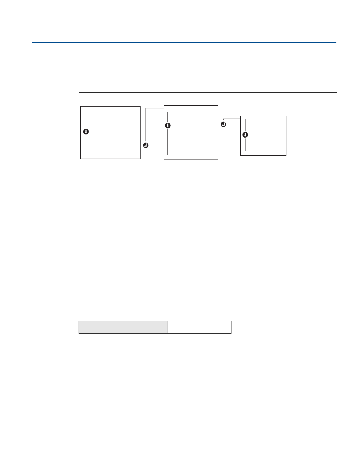
Follow flow chart to select the desired mapped variables. Use the SCROLL and ENTER buttons to select
each variable. Save by selecting SAVE as indicated on the LCD screen when prompted. See Figure 2-4 on
page 12 for an example of a mapped variable with the LOI.
Figure 2-4. Mapping Variables with LOI
2.6.2 Configuring the sensor(s)
Reference Manual
00809-0200-4728, Rev SA
Sensor configuration includes setting the information for:
Sensor type
Connection type
Units
Damping values
Sensor serial number
RTD 2-wire offset
Field Communicator
The configure sensors method will guide you through the configuration of all necessary settings
associated with configuring a sensor including:
For a full list of Sensor Types available with the Rosemount 644 Transmitter and their associated levels of
accuracy.
From the HOME screen, enter the Fast Key sequence.
Device Dashboard Fast Keys
2, 1, 1
AMS Device Manager
1. Right click on the device and select Configure.
2. In the left navigation pane select Manual Setup and select the Sensor 1or Sensor 2 tab depending
on the need.
12
3. Individually select the sensor type, connection, units and other sensor related information as desired
from the drop down menus on the screen.
4. Select Apply when complete.
Configuration

Reference Manual
VIEW SENSORVIEW SENSOR
SENSOR CONFIGSENSOR CONFIG
BACK TO MENU
EXIT MENU
VIEW S1 CONFIG
VIEW S2 CONFIG*
BACK TO MENU
EXIT MENU
VIEW CONFIG
SENSOR CONFIG
SENSOR CONFIG
UNITS
RERANGE
LOOP TEST
DISPLAY
EXTENDED MENU
EXIT MENU
SENSOR 1 CONFIG
SENSOR 2 CONFIG*
BACK TO MENU
EXIT MENU
00809-0200-4728, Rev SA
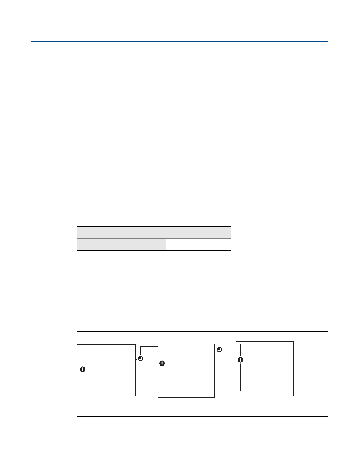
LOI
Reference Figure 2-5 for guidance on where to find Sensor Configuration in the LOI menu.
Figure 2-5. Configuring Sensors with LOI
* Available only if option code (S) or (D) is ordered.
Contact an Emerson™ representative for information on the temperature sensors, thermowells, and
accessory mounting hardware that is available through Emerson.
2-wire RTD offset
Configuration
July 2018
The 2-wire offset feature allows the measured lead wire resistance to be input and corrected for, which
results in the transmitter adjusting its temperature measurement for the error caused by this added
resistance. Because of a lack of lead wire compensation within the RTD, temperature measurements
made with a 2-wire RTD are often inaccurate.
This feature can be configured as a subset of the Sensor Configuration process in the Field
Communicator, AMS Device Manager, and the LOI.
To utilize this feature properly perform the following steps:
1. Measure the lead wire resistance of both RTD leads after installing the 2-wire RTD and Rosemount
644 Transmitter.
2. Navigate to the 2-wire RTD Offset parameter.
3. Enter the total measured resistance of the two RTD leads at the 2-wire Offset prompt to ensure
proper adjustment. The transmitter will adjust its temperature measurement to correct the error
caused by lead wire resistance.
Field Communicator
From the HOME screen, enter the Fast Key sequence.
Device Dashboard Fast Keys
2, 1, 1
AMS Device Manager
1. Right click on the device and select Configure.
Config uration
2. In the left navigation pane select Manual Setup and select the Sensor 1or Sensor 2 tab depending
on the need. Find the 2-wire offset text field and enter the value.
3. Select Apply when complete.
13
Configuration
CHANGE ALLCHANGE ALL
SENSOR 1 UNITS
SENSOR 2 UNITS*
DIFF UNITS*
AVERAGE UNITS*
1ST GOOD UNITS**
BACK TO MENU
EXIT MENU
DEG C UNITS
DEG F UNITS
DEG R UNITS
KELVIN UNITS
MV UNITS
OHM UNITS
BACK TO MENU
EXIT MENU
VIEW CONFIG
SENSOR CONFIG
UNITS
UNITS
RERANGE
LOOP TEST
DISPLAY
EXTENDED MENU
EXIT MENU
July 2018
2.6.3 Setting output units
The Units can be configured for a number of different parameters in the Rosemount 644 Transmitter.
Individual Units can be configured for:
Sensor 1
Sensor 2
Te rminal temperature
Differential temperature
Average temperature
First good temperature
Each of the base parameters and calculated outputs from those values can have a unit of measure
associated with it. Set the transmitter output to one of the following engineering units:
Celsius
Fahrenheit
Rankine
Kelvin
Ohms
Millivolts
Reference Manual
00809-0200-4728, Rev SA
Field Communicator
From the HOME screen, enter the Fast Key sequence.
HART 5 HART 7
Device Dashboard Fast Keys
2, 2, 1, 4 2, 2, 1, 5
AMS Device Manager
1. Right click on the device and select Configure.
2. In the left navigation pane select Manual Setup. The unit fields for various variables are spread over
the Manual Setup tabs, click through the tabs and change the desired units.
3. Select Apply when complete.
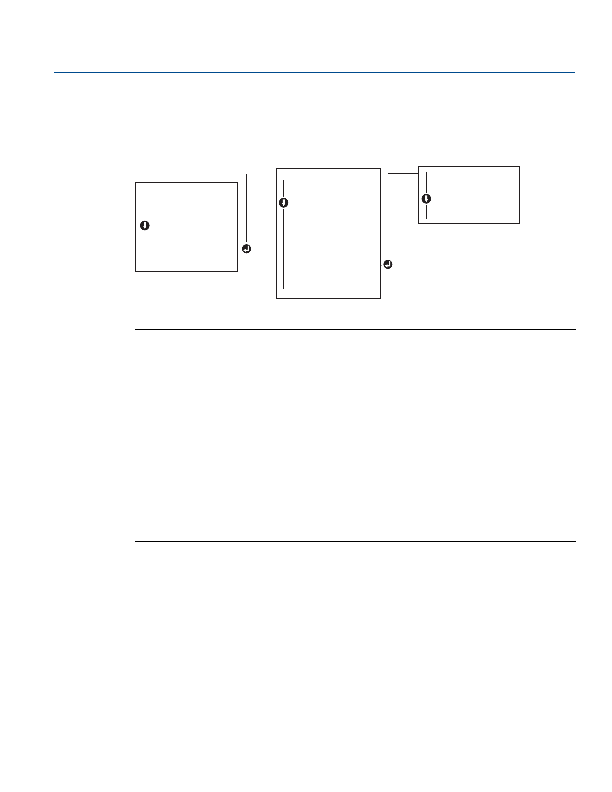
LOI
Reference the below image for where to find the Units configuration in the LOI menu.
Figure 2-6. Configuring Units with LOI
14
* Available only if option code (S) or (D) is ordered.
** Available only if option codes (S) and (DC) are both ordered, or if option codes (D) and (DC) are both ordered.
Configuration

Reference Manual
00809-0200-4728, Rev SA
Note
The list of choices available for Units after the primary menu is dependent on your Sensor configuration
settings.
2.7 Configure dual sensor options
Dual-sensor configuration deals with the functions that can be used with a transmitter ordered with Dual
Sensor inputs. In the Rosemount 644 Transmitter these functions include:
Differential temperature
Average temperature
Hot Backup
– First good temperature (requires options S and DC, or options D and DC)
2.7.1 Differential temperature configuration
The Rosemount 644 Transmitter ordered and configured for dual-sensors can accept any two inputs then
display the differential temperature between them. Use the following procedures to configure the
transmitter to measure differential temperature.
™
and sensor drift alert diagnostics (requires option code DC)
Configuration
July 2018
Note
This procedure assumes the differential temperature is a calculated output of the device but does not
re-assign it as the primary variable. If it desired for Differential to be the transmitter’s primary variable
see “Mapping the HART variables” on page 11 to set it to PV.
Field Communicator
From the HOME screen, enter the Fast Key sequence.
Device Dashboard Fast Keys
2, 2, 3, 1
AMS Device Manager
1. Right click on the device and select Configure.
2. In the left navigation pane choose Manual Setup.
3. On the Calculated Output Tab find the Differential Temperature group box.
4. Select Units and Damping settings then select Apply when complete.
Config uration
15

Configuration
CHANGE ALL
SENSOR 1 UNITS
SENSOR 2 UNITS*
DIFFRNTL UNITS*
DIFFRNTL UNITS*
AVERAGE UNITS*
1
ST
GOOD UNITS**
BACK TO MENU
EXIT MENU
DEG C UNITS
DEG F UNITS
DEG R UNITS
KELVIN UNITS
MV UNITS
OHM UNITS
BACK TO MENU
EXIT MENU
VIEW CONFIG
SENSOR CONFIG
UNITS
UNITS
RERANGE
LOOP TEST
DISPLAY
EXTENDED MENU
EXIT MENU
CALIBRAT
DAMPING
DAMPING
VARIABLE MAP
TAG
ALARM SAT VALUES
PASSWORD
....
PV DAMP
SENSOR 1 DAMP
SENSOR 2 DAMP*
DIFFRNTL
DIFFRNTL DAMP*DAMP*
AVERAGE DAMP*
1ST GOOD DAMP**
BACK TO MENU
EXIT MENU
VIEW CONFIG
SENSOR CONFIG
UNITS
RERANGE
LOOP TEST
DISPLAY
EXTENDED MENU
EXTENDED MENU
EXIT MENU
July 2018
Reference Manual
00809-0200-4728, Rev SA
LOI
To configure the Differential Temperature on the LOI, the Units and Damping values must be set
separately. Reference figures below for where to find these in the menu.
Figure 2-7. Configuring Differential Units with LOI
* Available only if option code (S) or (D) is ordered.
** Available only if option codes (S) and (DC) are both ordered, or if option codes (D) and (DC) are both ordered.
Figure 2-8. Configuring Differential Damping with LOI
2.7.2 Average temperature configuration
16
* Available only if option code (S) or (D) is ordered.
** Available only if option codes (S) and (DC) are both ordered, or if option codes (D) and (DC) are both ordered.
The Rosemount 644 Transmitter ordered and configured for dual-sensors can output and display the
Average temperature of any two inputs. Use the following procedures to configure the transmitter to
measure the average temperature:
Note
This procedure assumes the average temperature is a calculated output of the device but does not
re-assign it as the primary variable. If it is desired for average to be the transmitter’s primary variable see
“Mapping the HART variables” on page 11 to set it to PV.
Field Communicator
From the HOME screen, enter the Fast Key sequence.
Device Dashboard Fast Keys
2, 2, 3, 3
Configuration

Reference Manual
CHANGE ALL
SENSOR 1 UNITS
SENSOR 2 UNITS*
DIFFRNTL UNITS*
AVERAGE UNITS
AVERAGE UNITS*
1ST GOOD UNITS**
BACK TO MENU
EXIT MENU
DEG C UNITS
DEG F UNITS
DEG R UNITS
KELVIN UNITS
MV UNITS
OHM UNITS
BACK TO MENU
EXIT MENU
VIEW CONFIG
SENSOR CONFIG
UNITS
UNITS
RERANGE
LOOP TEST
DISPLAY
EXTENDED MENU
EXIT MENU
CALIBRAT
DAMPING
DAMPING
VARIABLE MAP
TAG
ALARM SAT VALUES
PASSWORD
....
PV DAMP
SENSOR 1 DAMP
SENSOR 2 DAMP*
DIFFRNTL DAMP*
AVERAGE DAMP
AVERAGE DAMP*
1ST GOOD DAMP**
BACK TO MENU
EXIT MENU
VIEW CONFIG
SENSOR CONFIG
UNITS
UNITS
RERANGE
LOOP TEST
DISPLAY
EXTENDED MENU
EXIT MENU
00809-0200-4728, Rev SA
AMS Device Manager
1. Right click on the device and select Configure.
2. In the left navigation pane select Manual Setup.
3. On the Calculated Output Tab find the Average Temperature group box.
4. Select Units and Damping settings then select Apply when complete.
LOI
To configure average temperature on the LOI, the units and damping values must be set separately.
Reference Figure 2-9 and Figure 2-10 below for where to find these in the menu.
Figure 2-9. Configuring Average Units with LOI
Configuration
July 2018
* Available only if option code (S) or (D) is ordered.
** Available only if option codes (S) and (DC) are both ordered, or if option codes (D) and (DC) are both ordered.
Figure 2-10. Configuring Average Damping with LOI
* Available only if option code (S) or (D) is ordered.
** Available only if option codes (S) and (DC) are both ordered, or if option codes (D) and (DC) are both ordered.
Config uration
17

Configuration
July 2018
Note
If Sensor 1 and/or Sensor 2 should fail while PV is configured for average temperature and Hot Backup is
not enabled, the transmitter will go into alarm. For this reason, it is recommended when PV is Sensor
Average, that Hot Backup be enabled when dual-element sensors are used, or when two temperature
measurements are taken from the same point in the process. If a sensor failure occurs when Hot Backup
is enabled, while PV is Sensor Average, three scenarios could result:
If Sensor 1 fails, the average will only be reading from Sensor 2, the working sensor
If Sensor 2 fails, the average will only be reading from Sensor 1, the working sensor
If both sensors fail simultaneously, the transmitter will go into alarm and the status available (via
HART) states that both Sensor 1 and Sensor 2 have failed
In the first two scenarios, the 4–20 mA signal is not disrupted and the status available to the control
system (via HART) specifies which sensor has failed.
2.7.3 Hot Backup configuration
The Hot Backup feature configures the transmitter to automatically use Sensor 2 as the primary sensor if
Sensor 1 fails. With Hot Backup enabled, the primary variable (PV) must either be first good or average.
See the “NOTE” directly above for details on using Hot Backup when the PV is set to Average.
Reference Manual
00809-0200-4728, Rev SA
Sensors 1 or 2 can be mapped as the secondary variable (SV), tertiary variable (TV), or quaternary
variable (QV). In the event of a primary variable (Sensor 1) failure, the transmitter enters Hot Backup
mode and Sensor 2 becomes the PV. The 4–20 mA signal is not disrupted, and a status is available to the
control system through HART that Sensor 1 has failed. An LCD display, if attached, displays the failed
sensor status.
While configured to Hot Backup, if Sensor 2 fails but Sensor 1 is still operating properly, the transmitter
continues to report the PV 4–20 mA analog output signal, while a status is available to the control
system through HART that Sensor 2 has failed.
Resetting Hot Backup
In Hot Backup mode, if Sensor 1 does fail and Hot Backup is initiated, the transmitter will not revert back
to Sensor 1 to control the 4–20 mA analog output until the Hot Backup mode is reset by re-enabling
through HART, re-setting it through the LOI or by briefly powering down the transmitter.
Field Communicator
The field communicator will walk you through a method to correctly configure the necessary elements
of the Hot Backup feature.
From the HOME screen, enter the Fast Key sequence.
Device Dashboard Fast Keys
2, 1, 5
AMS Device Manager
18
1. Right click on the device and select Configure.
2. In the left navigation pane select Manual Setup.
3. On the Diagnostics Tab find the Hot Backup group box.
4. Choose the button Configure Hot Backup or Reset Hot Backup depending on the desired function
and walk through the guided steps.
5. Select Apply when complete.
Configuration
Reference Manual
CALIBRAT
DAMPING
VARIABLE MAP
TAG
ALM SAT VALUES
PASSWORD
SIMULATE
HART REV
HOT BACK CONFIG**
HOT BACK CONFIG**
DRIFT ALERT**
....
HOT BACK MODE
HOT BACK PV
HOT BACK RESET
BACK TO MENU
EXIT MENU
VIEW CONFIG
SENSOR CONFIG
UNITS
RERANGE
LOOP TEST
DISPLAY
EXTENDED MENU
EXTENDED MENU
EXIT MENU
00809-0200-4728, Rev SA
LOI
To configure Hot Backup on the LOI, enable the mode and set the PV values. Reference Figure 2-11 for
where to find these in the menu.
Figure 2-11. Configuring Hot Backup with LOI
* Available only if option code (S) or (D) is ordered.
** Available only if option codes (S) and (DC) are both ordered, or if option codes (D) and (DC) are both ordered.
Configuration
July 2018
For information on using Hot Backup in conjunction with the HART Tri-Loop™ see “Using the transmitter
with the HART Tri-Loop” on page 35.
2.7.4 Sensor drift alert configuration
The sensor drift alert command allows the transmitter to set a warning flag (through HART), or go into
analog alarm when the temperature difference between sensor 1 and sensor 2 exceeds a user-defined
limit.
This feature is useful when measuring the same process temperature with two sensors, ideally when
using a dual-element sensor. When sensor drift alert mode is enabled, the user sets the maximum
allowable difference, in engineering units, between sensor 1 and sensor 2. If this maximum difference is
exceeded, a sensor drift alert warning flag will be set.
Though it defaults to WARNING, when configuring the transmitter for sensor drift alert, the user also has
the option of specifying the analog output of the transmitter go into ALARM when sensor drifting is
detected.
Note
Using dual sensor configuration in the Rosemount 644 Transmitter, the transmitter supports the
configuration and simultaneous use of Hot Backup and sensor drift alert. If one sensor fails, the
transmitter switches output to use the remaining good sensor. Should the difference between the two
sensor readings exceed the configured threshold, the AO will go to alarm indicating the sensor drift
condition. The combination of sensor drift alert and Hot Backup improves sensor diagnostic coverage
while maintaining a high level of availability. Refer to the Rosemount 644 FMEDA report for the impact
on safety.
Config uration
19

Configuration
CALIBRAT
DAMPING
VARIABLE MAP
TAG
ALM SAT VALUES
PASSWORD
SIMULATE
HART REV
HOT BACK CONFIG**
DRIFT ALERT**
DRIFT ALERT**
....
DRIFT MODE
DRIFT LIMIT
DRIFT UNITS
DRIFT DAMP
BACK TO MENU
EXIT MENU
VIEW CONFIG
SENSOR CONFIG
UNITS
RERANGE
LOOP TEST
DISPLAY
EXTENDED MENU
EXTENDED MENU
EXIT MENU
July 2018
Reference Manual
00809-0200-4728, Rev SA
Field Communicator
The Field Communicator will walk you through a method to correctly configure the necessary elements
of a sensor drift alert feature.
From the HOME screen, enter the Fast Key sequence.
Device Dashboard Fast Keys
2, 1, 6
AMS Device Manager
1. Right click on the device and select Configure.
2. On the Diagnostics Tab find the Sensor Drift Alert group box.
3. Select to Enable the Mode and fill in the Units, Threshold and Damping values from the drop downs
provided or select the Configure Sensor Drift Alert button and walk through the guided steps.
4. Select Apply when complete.
LOI
To configure sensor drift alert on the LOI, enable the mode, then set the PV, drift limit, and value for drift
alert damping all separately. Reference figure below for where to find these in the menu.
Figure 2-12. Configuring Sensor Drift Alert with LOI
20
* Available only if option code (S) or (D) is ordered.
** Available only if option codes (S) and (DC) are both ordered, or if option codes (D) and (DC) are both ordered.
Note
Enabling the drift alert option to WARNING will set a flag (through the HART communications) whenever
the maximum acceptable difference between sensor 1 and sensor 2 has been exceeded. For the
transmitter’s analog signal to go into ALARM when drift alert is detected, select alarm during the
configuration process.
Configuration

Reference Manual
ENTER VALUESENTER VALUES
BACK TO MENU
EXIT MENU
LRVLRV
URVURV
BACK TO MENU
EXIT MENU
VIEW CONFIG
SENSOR CONFIG
UNITS
RERANGE
RERANGE
LOOP TEST
DISPLAY
EXTENDED MENU
EXIT MENU
00809-0200-4728, Rev SA
2.8 Configure device outputs
2.8.1 Re-range the transmitter
Re-ranging the transmitter sets the measurement range to the limits of the expected readings for a
certain application. Setting the measurement range to the limits of expected readings maximizes
transmitter performance; the transmitter is most accurate when operated within the expected
temperature range for the application.
The range of expected readings is defined by the Lower Range Value (LRV) and Upper Range Value (URV).
The transmitter range values can be reset as often as necessary to reflect changing process conditions.
For a complete listing of Range and Sensor limits.
Note
The re-range functions should not be confused with the trim functions. Although the re-range function
matches a sensor input to a 4–20 mA output, as in conventional calibration, it does not affect the
transmitter’s interpretation of the input.
Select from one of the methods below to re-range the transmitter.
Configuration
July 2018
Field Communicator
From the HOME screen, enter the Fast Key sequence.
Device Dashboard Fast Keys
Lower range value Upper range value
2, 2, 5, 5, 3 2, 2, 5, 5, 2
AMS Device Manager
1. Right click on the device and select Configure.
2. In the left navigation pane select Manual Setup.
3. On the Analog Output Tab find the Primary Variable Configuration group box.
4. Change the Upper Range Value and Lower Range Value to their desired settings.
5. Select Apply when complete.
LOI
Reference the image below to find the range value configuration path on the LOI.
Figure 2-13. Re-ranging the Transmitter with LOI
Config uration
21

Configuration
Damped Value NP–()
2TU–
2TU+
-----------------
× P+=
July 2018
2.8.2 Damping
The damping function changes the response time of the transmitter to smooth variations in output
readings caused by rapid changes in input. Determine the appropriate damping setting based on the
necessary response time, signal stability, and other requirements of the loop dynamics of the system.
The default damping value is 5.0 seconds and can be reset to any value between 1 and 32 seconds.
The value chosen for damping affects the response time of the transmitter. When set to zero (disabled),
the damping function is off and the transmitter output reacts to changes in input as quickly as the
intermittent sensor algorithm allows. Increasing the damping value increases transmitter response time.
With damping enabled, if the temperature change is within 0.2 percent of the sensor limits, the
transmitter measures the change in input every 500 milliseconds (for a single sensor device) and outputs
values according to the following relationship:
P = previous damped value
N = new sensor value
T = damping time constant
Reference Manual
00809-0200-4728, Rev SA
U = update rate
At the value to which the damping time constant is set, the transmitter output is at 63 percent of the
input change and it continues to approach the input according to the damping equation above.
For example, as illustrated in Figure 2-14, if the temperature undergoes a step change—within 0.2
percent of the sensor limits—from 100 degrees to 110 degrees, and the damping is set to 5.0 seconds,
the transmitter calculates and reports a new reading every 500 milliseconds using the damping
equation. At 5.0 seconds, the transmitter outputs 106.3 degrees, or 63 percent of the input change, and
the output continues to approach the input curve according to the equation above.
For information regarding the damping function when the input change is greater than 0.2 percent of
the sensor limits, refer to “Intermittent sensor detection” on page 28.
Figure 2-14. Change in Input vs. Change in Output with Damping Set to Five Seconds
22
Configuration
 Loading...