

Page 1
Product Data Sheet
00813-0100-4728, Rev UE
February 2019
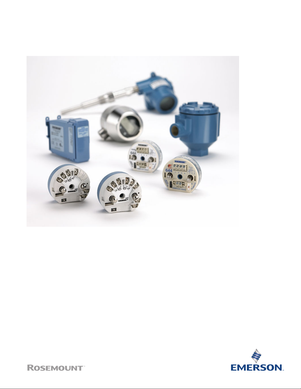
Rosemount™644 Temperature Transmitter
The most versatile temperature transmitter
Reduce complexity and simplify the day-to-day operations of your diverse temperature applications with
the versatile Rosemount™ 644 family of temperature transmitters. Make better decisions for your process
with the new and easy to use Rosemount 644 Transmitter capabilities including: diagnostics, safety
certification, integral transient protection, and display options.
Page 2

February 2019
Features and benefits
Fulfill your needs within one model family with a customizable transmitter design
■
DIN head mount, field mount, and rail mount form factors
■
4–20 mA/HART® with Selectable Revisions, FOUNDATION™ Fieldbus or PROFIBUS® PA Protocol support
■
SIL3 Capable: IEC 61508 certified by an accredited third party agency for use in safety instrumented systems up to SIL 3
[minimum requirement of single use (1oo1) for SIL 2 and redundant use (1oo2) for SIL 3]
■
Enhanced display with Local Operator Interface (LOI)
■
LCD display
■
Integral transient protection
■
Enhanced accuracy and stability
■
Transmitter-sensor matching with Callendar-Van Dusen constants
■
Variety of enclosures
Contents
Features and benefits........................................................................................................................................................................ 2
Ordering Information........................................................................................................................................................................ 5
Specifications ................................................................................................................................................................................. 15
Dimensional drawings..................................................................................................................................................................... 29
Specifications and reference data for Rosemount 644 HART (Device Revision 7 or Previous)........................................................... 42
Product Certifications......................................................................................................................................................................50
2 www.emerson.com
Page 3
February 2019
Rosemount 644 selection guide
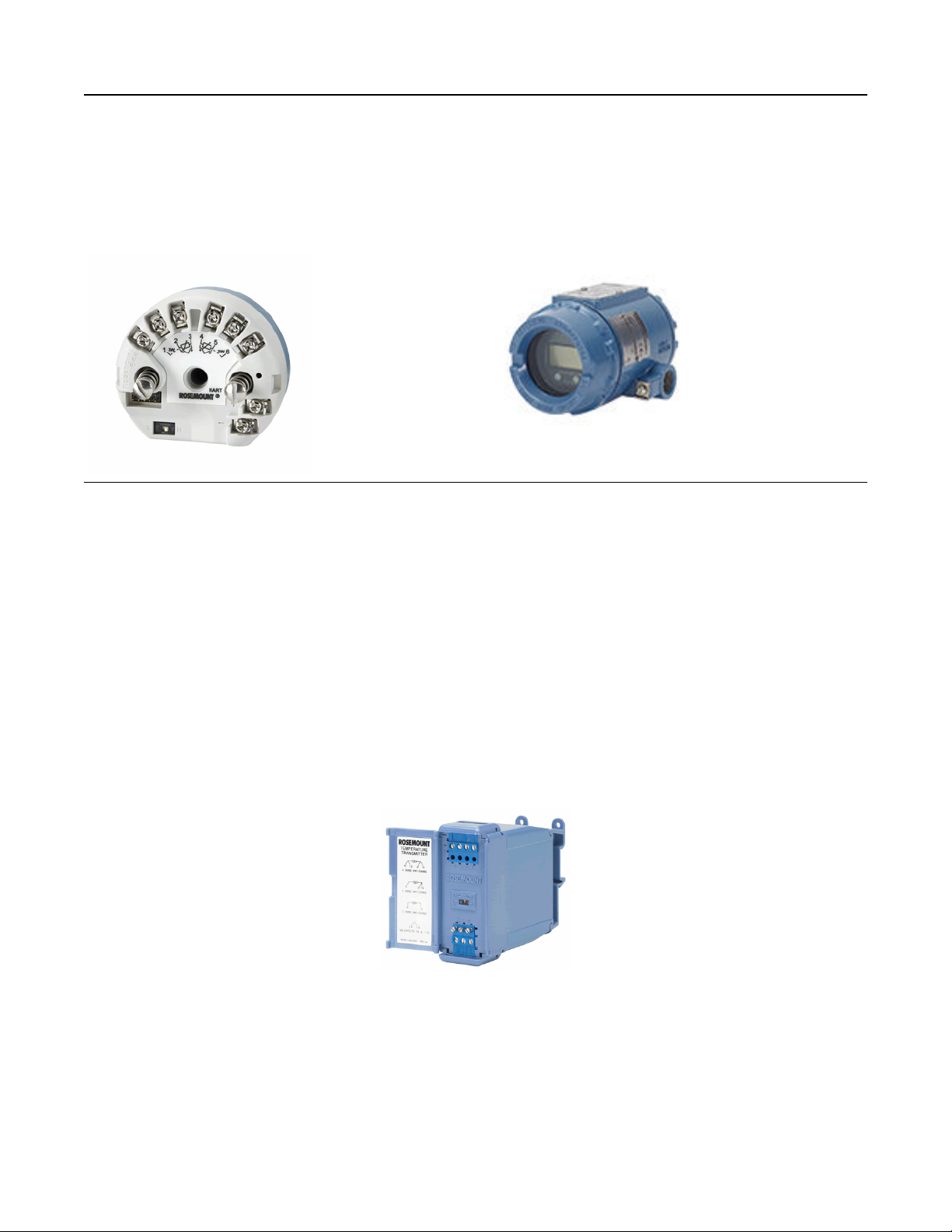
Rosemount 644 HART Transmitters
HART head mount and field mount
■
Single or dual sensor inputs for RTD, thermocouple, mV, and Ohm
■
DIN A Head mount and field mount transmitters
■
SIL3 Capable: IEC 61508 certified by an accredited third party agency for use in safety instrumented systems up to SIL 3
(minimum requirement of single use [1oo1] for SIL 2 and redundant use [1oo2] for SIL 3)
■
LCD display
■
Enhanced display with LOI
■
Integral transient protection
■
Diagnostic suite
■
Enhanced accuracy and stability
■
Transmitter–sensor matching with Callendar-Van Dusen constants
HART rail mount
■
Single sensor input for RTD, thermocouple, mV, and Ohm
■
Custom alarm and saturation levels
■
Transmitter–sensor matching with Callendar-Van Dusen constants
■
Hardware alarm switch
3
Page 4
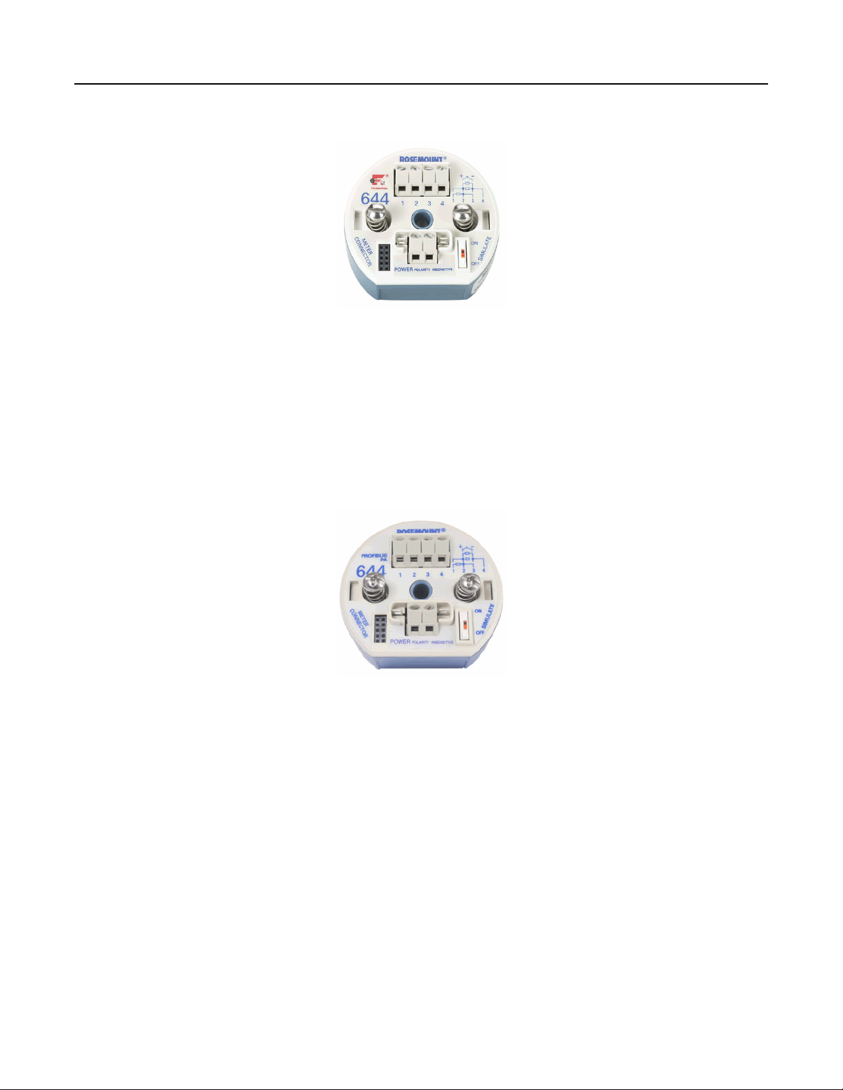
Rosemount 644 FOUNDATION Fieldbus
■
Single sensor input for RTD, thermocouple, mV, and Ohm
■
DIN A head mount transmitter
■
Standard function blocks: two analog inputs, one PID, and one backup Link Active Scheduler (LAS)
■
LCD display
■
ITK 5.01 compliant
■
Transmitter–sensor matching with Callendar-Van Dusen constants
■
Integral transient protection
February 2019
Rosemount 644 PROFIBUS PA
■
Single sensor input for RTD, thermocouple, mV, and Ohm
■
DIN A head mount transmitter
■
Standard function blocks: one physical, one transducer, and one analog output
■
LCD display
■
Compliant to PROFIBUS PA Profile 3.02
■
Transmitter–sensor matching with Callendar-Van Dusen constants
Easy to use human-centered designs to make your job simple
■
Diagnostic information and process health at your fingertips with intuitive Device Dashboards (DD).
■
Communication clips are easily accessible when an LCD display is attached.
■
Easy wiring practices with captive sensor screw terminals, an optimized wiring diagram, and field mount enclosure option.
Optimize plant efficiency and increase visibility into the process with an expansive diagnostic offering
■
Keep your process up and running with the Hot Backup™ feature where if your primary sensor fails, a second sensor seamlessly
takes over and prevents the measurement failure.
■
Tighten control with sensor drift alert that detects drifting sensors and pro-actively notifies the user.
4 www.emerson.com
Page 5

February 2019
■
Enable predictive maintenance practices with thermocouple degradation diagnostic that monitors the health of the
thermocouple loop.
■
Improve quality with minimum and maximum temperature tracking that records temperature extremes of the process and the
ambient environment.
Ordering Information
The Rosemount 644 is a versatile temperature transmitter that delivers field reliability and advanced accuracy and stability to meet
demanding process needs.
Transmitter features include:
■
HART/4–20 mA with Selectable Revision 5 and 7 (option code A), FOUNDATION Fieldbus (option code F) or PROFIBUS PA (option
code W)
■
DIN A head mount, field mount, or rail mount transmitter styles
■
Head mount - Dual sensor (option code S)
■
Field mount - Dual sensor (option code D)
■
Safety Certified to IEC 61508 with Certificate of FMEDA Data (option code QT)
■
LCD display (option code M5)
■
LOI (option code M4)
■
Advanced diagnostics (option codes DC and DA1)
■
Enhanced transmitter accuracy and stability (option code P8)
■
Transmitter-sensor matching (option code C2)
Specification and selection of product materials, options, or components must be made by the purchaser of the equipment. See
Specifications and reference data for Rosemount 644 HART (Device Revision 7 or Previous) for more information on material
selection.
Table 1: Rosemount 644 Temperature Transmitter Ordering Information
The starred offerings (★) represent the most common options and should be selected for best delivery. The non-starred offerings
are subject to additional delivery lead time.
● = Available
– = Not Available
Model Product description
644 Temperature transmitter
Transmitter type
H DIN A head mount - single sensor input ★
5
Page 6

February 2019
Table 1: Rosemount 644 Temperature Transmitter Ordering Information (continued)
Model Product description
R Rail mount - single sensor input ★
S DIN A head mount - dual sensor input (HART only) ★
(1)
F
D
(1)
Field mount - single sensor input (HART only) ★
Field mount - dual sensor input (HART only) ★
Output Head Rail
A 4–20 mA with digital signal based on HART protocol ● ● ★
(2)
F
FOUNDATION Fieldbus digital signal (includes 2 AI function blocks and
● – ★
Backup LAS)
(2)
W
PROFIBUS PA digital signal ● – ★
Product certifications
Hazardous locations certificates (consult factory for availability
(3)
) A F W A
NA No approval ● ● ● ● ★
E5 USA Explosion-proof; Dust Ignition-proof ● ● ● – ★
Head Rail
A F W A
I5 USA Intrinsically Safe; Non-incendive ● ● ● ● ★
K5 USA Explosionproof; Intrinsically Safe; Non-incendive; Dust Ignition-
● ● ● – ★
proof
NK IECEx Dust ● ● – – ★
KC USA and Canada Intrinsically Safe and Non-incendive – – – ● ★
KB USA and Canada: Explosion-proof; Intrinsically Safe; Non-incendive;
● – – – ★
Dust Ignition-proof
KD USA, Canada, and ATEX Explosionproof, Intrinsically Safe ● ● ● – ★
I6 Canada Intrinsically Safe ● ● ● ● ★
K6 Canada Explosionproof; Intrinsically Safe; Non-incendive; Dust
● ● ● – ★
Ignition-proof
I3 China Intrinsic Safety ● ● – – ★
E3 China Flameproof ● ● ● – ★
N3 China Type n ● ● – – ★
E1 ATEX Flameproof ● ● ● – ★
N1 ATEX Type n ● ● ● – ★
NC ATEX Type n Component ● ● ● ● ★
K1 ATEX Flameproof; Intrinsic Safety; Type n; Dust ● ● ● – ★
ND ATEX Dust Ignition–Proof ● ● ● – ★
KA Canada and ATEX: Explosion proof; Intrinsically Safe; Non-incendive ● – – – ★
I1 ATEX Intrinsic Safety ● ● ● ● ★
E7 IECEx Flameproof ● ● ● – ★
6 www.emerson.com
Page 7
February 2019
Table 1: Rosemount 644 Temperature Transmitter Ordering Information (continued)
Model Product description
I7 IECEx Intrinsic Safety ● ● ● ● ★
N7 IECEx Type n ● ● ● – ★
NG IECEx Type n Component ● ● ● ● ★
K7 IECEx Flameproof; Intrinsic Safety; Type n; Dust ● ● – – ★
I2 INMETRO Intrinsic Safety ● ● ● – ★
E4 Japan Flameproof ● ● – – ★
I4 Japan Intrinsic Safety ● ● – – ★
E2 INMETRO Flameproof ● ● ● – ★
EM Technical Regulations Customs Union (EAC) Flameproof ● ● ● – ★
IM Technical Regulations Customs Union (EAC) Intrinsic Safety ● ● ● ● ★
KM Technical Regulations Customs Union (EAC) Flameproof, Intrinsic
● ● ● – ★
Safety, and Dust-Ignitionproof
Consult factory on availability.
(1)
Only available with H (single sensor), not S(dual sensor).
(2)
See Table 2 for the validity of enclosures with individual approval options.
(3)
Options
Head Rail
A F W A
Plantweb™ standard diagnostic functionality
(1)
DC
DA1 HART sensor and process diagnostic suite: Thermocouple diagnostic
Diagnostics: Hot Backup and sensor drift alert ● – – – ★
● – – – ★
and min/max tracking
Enclosure options
Housing style Material Entry size Diameter
(2) (3)
J5
(3)
J6
R1 Rosemount
Universal junction
box, 2 entries
Universal junction
box, 2 entries
connection head, 2
Aluminum M20 × 1.5 3-in. (76
mm)
Aluminum ½–14 NPT 3-in. (76
mm)
Aluminum M20 × 1.5 3-in. (76
mm)
● ● ● – ★
● ● ● – ★
● ● ● – ★
entries
R2 Rosemount
connection head, 2
entries
(2)
J1
Universal junction
box, 3 entries
J2 Universal junction
box, 3 entries
Aluminum ½–14 NPT 3-in. (76
mm)
Aluminum M20 × 1.5 3.5-in. (89
mm)
Aluminum ½–14 NPT 3.5-in. (89
mm)
● ● ● – ★
● ● ● – ★
● ● ● – ★
7
Page 8

D1
D2
J3
(2)
(1) (2) (4)
(1) (4)
Field mount
housing, separate
terminal
compartment
Field mount
housing, separate
terminal
compartment
Universal junction
box, 3 entries
Aluminum M20 × 1.5 3.5-in. (89
mm)
Aluminum ½–14 NPT 3.5-in. (89
mm)
Cast SST M20 × 1.5 3.5-in. (89
mm)
February 2019
– – – – ★
– – – – ★
● ● ● –
J4 Universal junction
box, 3 entries
(2) (3)
J7
Universal junction
box, 2 entries
(3)
J8
Universal junction
box, 2 entries
R3 Rosemount
connection head, 2
entries
R4 Rosemount
connection head, 2
entries
S1 Connection head, 2
entries
S2 Connection head, 2
entries
S3 Connection head, 2
entries
S4 Connection head, 2
entries
Mounting bracket
(5)
Cast SST ½–14 NPT 3.5-in. (89
mm)
Cast SST M20 × 1.5 3-in. (76
mm)
Cast SST ½–14 NPT 3-in. (76
mm)
Cast SST M20 × 1.5 3-in. (76
mm)
Cast SST ½–14 NPT 3-in. (76
mm)
Polished SST ½–14 NPT 3-in. (76
mm)
Polished SST ½–14 NPSM 3-in. (76
mm)
Polished SST M20 × 1.5 3-in. (76
mm)
Polished SST M20 × 1.5,
M24 × 1.4
3-in. (76
mm)
● ● ● –
● ● ● –
● ● ● –
● ● ● –
● ● ● –
● ● ● –
● ● ● –
● ● ● –
● ● ● –
B4 316 SST U-bolt mounting bracket, 2-in. pipe mount ● ● ● ● ★
B5 “L” mounting bracket for 2-in. pipe or panel mounting ● ● ● ● ★
Display and interface options
M4 LCD display with LOI ● – – – ★
M5 LCD display ● ● ● – ★
Software configuration
C1 Custom configuration of date, descriptor and message (requires CDS
● ● ● ● ★
with order)
Enhanced performance
(6)
P8 Enhanced transmitter accuracy and stability ● – – – ★
Alarm level configuration
A1 NAMUR alarm and saturation levels, high alarm ● – – ● ★
Head Rail
8 www.emerson.com
Page 9

February 2019
A F W
A
CN NAMUR alarm and saturation levels, low alarm ● – – ● ★
C8 Low alarm (standard Rosemount alarm and saturation values) ● – – ● ★
Line filter
F5 50 Hz line voltage filter ● ● ● ● ★
F6 60 Hz line voltage filter ● ● ● ● ★
Sensor trim
C2 Transmitter sensor matching - trim to specific Rosemount RTD
● ● ● ● ★
calibration schedule (CVD constants)
5-Point calibration option
C4 5-point calibration (use option code Q4 to generate a calibration
● ● ● ● ★
certificate)
Calibration certificate
Q4 Calibration certificate (3-point calibration with certificate) ● ● ● ● ★
QP Calibration certification and tamper evident seal ● – – – ★
Custody transfer
D4 MID Custody Transfer (Europe) ● – – – ★
Quality certification for safety
QT Safety Certified to IEC 61508 with certificate of FMEDA data ● – – – ★
Shipboard certification
SBS American Bureau of Shipping (ABS) Type Approval ● ● ● – ★
SBV Bureau Veritas (BV) Type Approval ● ● ● – ★
SDN Det Norske Veritas (DNV) Type Approval ● ● ● – ★
SLL Lloyd's Register (LR) Type Approval ● ● ● – ★
External ground
G1 External ground lug assembly (see External ground screw assembly ) ● ● ● – ★
Transient protection
(7) (8)
T1
Integral transient protector ● ● – – ★
Cable gland option
G2 Cable gland (7.5–11.99 mm) ● ● ● – ★
G7 Cable gland, M20 × 1.5, Ex e, blue polyamide (5–9 mm) ● ● ● – ★
Cover chain option
G3 Cover chain ● ● ● – ★
Conduit Electrical Connector
(9)
GE M12, 4-pin, male connector (eurofast®) ● ● ● – ★
GM A size mini, 4-pin, male connector (minifast®) ● ● ● – ★
External label
EL External label for ATEX Intrinsic Safety ● ● ● – ★
9
Page 10
February 2019
HART revision configuration
HR5 Configured for HART Revision 5 ● – – – ★
(10)
HR7
Configured for HART Revision 7 ● – – – ★
Assemble to options
XA Sensor specified separately and assembled to transmitter ● ● ● – ★
Extended product warranty
WR3 3-year limited warranty ● ● ● ● ★
WR5 5-year limited warranty ● ● ● ● ★
Typical rail mount model number: 644 R A I5
Typical head mount model number: 644 S A I5 DC DA1 J5 M5
Typical field mount model Nnumber: 644 F A I5 DC DA1 D1 M4 T1
Only available with S (dual sensor), not H(single sensor).
(1)
When ordered with XA, ½-in. NPT enclosure will come equipped with an M20 adapter with the sensor installed as a process ready.
(2)
Enclosure ships equipped with 50.8 mm (2-in.) SST pipe U-bolt mounting kit.
(3)
Available with Transmitter Type 644F or 644D only.
(4)
Bracket assembly only available with J1, J2, J3, J4, D1, and D2.
(5)
See Table 11 for Enhanced Accuracy specifications.
(6)
Transient Protection option requires the use of J1, J2, J3, or J4.
(7)
Transient Protection with Output option code F only available with NA, E3, I3, and N3 product certifications.
(8)
Available with Intrinsically Safe approvals only. For USA Intrinsically Safe or non-incendive approval (option code I5), install in accordance with
(9)
Rosemount drawing 03151-1009.
Configures the HART output to HART Revision 7. The device can be field configured to HART Revision 5 if needed.
(10)
Note
For additional options (e.g., K codes), contact your local Emerson representative.
Table 2: Rosemount 644 Enclosure Options Valid with Individual Approval Codes
Code Hazardous Location Approval Description Enclosure Options Valid with Approval
NA No approval J1, J2, J3, J4, R1, R2, R3, R4, J5, J6, J7, J8, S1, S2, S3,
S4, D1, D2
E5 USA Explosion proof; Dust Ignition-proof J1, J2, J3, J4, R1, R2, R3, R4, J5, J6, J7, J8, D1, D2
I5 USA Intrinsically Safe; Non-incendive J1, J2, J3, J4, R1, R2, R3, R4, J5, J6, J7, J8, D1, D2
K5 USA Explosion proof; Intrinsically Safe; Non-
J1, J2, J3, J4, R1, R2, R3, R4, J5, J6, J7, J8, D1, D2
incendive; Dust Ignition-proof
NK IECEx Dust J1, J2, J3, J4, R1, R2, R3, R4, J5, J6, J7, J8, D1, D2
KC USA and Canada Intrinsically Safe and Non-
Only available with Rail mount device
incendive
KB USA and Canada: Explosion proof; Intrinsically
J2, J4, R2, R4, J6, J8, D2
Safe; Non-incendive; Dust Ignition-proof
KD USA, Canada, and ATEX Explosion proof,
J2, J4, R2, R4, J6, J8, D2
Intrinsically Safe
I6 Canada Intrinsically Safe J1, J2, J3, J4, R1, R2, R3, R4, J5, J6, J7, J8, D1, D2
K6 Canada Explosion proof; Intrinsically Safe; Non-
J2, J4, R2, R4, J6, J8, D2
incendive; Dust Ignition-proof
I3 China Intrinsic Safety J1, J2, J3, J4, R1, R2, R3, R4, J5, J6, J7, J8, D1, D2
10 www.emerson.com
Page 11

February 2019
Table 2: Rosemount 644 Enclosure Options Valid with Individual Approval Codes (continued)
Code Hazardous Location Approval Description Enclosure Options Valid with Approval
E3 China Flameproof R1, R2, R3, R4, J1, J2, J3, J4, J5, J6, J7, J8, D1, D2
N3 China Type n R1, R2, R3, R4, J1, J2, J3, J4, J5, J6, J7, J8, D1, D2
E1 ATEX Flameproof J1, J2, J3, J4, R1, R2, R3, R4, J5, J6, J7, J8, D1, D2
N1 ATEX Type n J1, J2, J3, J4, R1, R2, R3, R4, J5, J6, J7, J8, D1, D2
NC ATEX Type n Component None
K1 ATEX Flameproof; Intrinsic Safety; Type n; Dust J1, J2, J3, J4, R1, R2, R3, R4, J5, J6, J7, J8, D1, D2
ND ATEX Dust Ignition-Proof J1, J2, J3, J4, R1, R2, R3, R4, J5, J6, J7, J8, D1, D2
KA Canada and ATEX: Explosion proof; Intrinsically
Safe; Non-incendive
I1 ATEX Intrinsic Safety J1, J2, J3, J4, R1, R2, R3, R4, J5, J6, J7, J8, S1, S2, S3,
E7 IECEx Flameproof J1, J2, J3, J4, R1, R2, R3, R4, J5, J6, J7, J8, D1, D2
I7 IECEx Intrinsic Safety J1, J2, J3, J4, R1, R2, R3, R4, J5, J6, J7, J8, S1, S2, S3,
N7 IECEx Type n J1, J2, J3, J4, R1, R2, R3, R4, J5, J6, J7, J8, D1, D2
NG IECEx Type n Component None
K7 IECEx Flameproof; Intrinsic Safety; Type n; Dust J1, J2, J3, J4, R1, R2, R3, R4, J5, J6, J7, J8, D1, D2
I2 INMETRO Intrinsic Safety J1, J2, J3, J4, R1, R2, R3, R4, J5, J6, J7, J8
E4 Japan Flameproof J2, J6
E2 INMETRO Flameproof R1, R2, R3, R4, J1, J2, J3, J4, J5, J6, J7, J8, D1, D2
KM Technical Regulations Customs Union (EAC)
Flameproof, Intrinsic Safety, and Dust-Ignition
proof
IM Technical Regulations Customs Union (EAC)
Intrinsic Safety
EM Technical Regulations Customs Union (EAC)
Flameproof
J2, J4, R2, R4, J6, J8, D2
S4, D1, D2
S4, D1, D2
J1, J2, J3, J4,J5,J6, J7, J8, R1, R2, R3, R4,
D1, D2, J1, J2, J3, J4,J5,J6, J7, J8, R1, R2, R3, R4, S1,
S2, S3, S4
J1, J2, J3, J4,J5,J6, J7, J8, R1, R2, R3, R4,
K2 INMETRO Flameproof, Intrinsic Safety R1, R2, R3, R4, J1, J2, J3, J4, J5, J6, J7, J8
Tagging
Hardware
■
13 characters total
■
Tags are adhesive or metal labels
■
Tag is permanently attached to transmitter
Software
The transmitter can store up to 32 characters for FOUNDATION Fieldbus and PROFIBUS PA or eight for HART protocol. If no characters
are specified, the first eight characters of the hardware tag are the default. An optional 32 character long software tag is available
when option code HR7 is ordered.
11
Page 12

February 2019
Considerations
External ground screw assembly
The external ground screw assembly can be ordered by specifying code G1 when an enclosure is specified. However, some
approvals include the ground screw assembly in the transmitter shipment, hence it is not necessary to order code G1. The table
below identifies which approval options include the external ground screw assembly and which do not.
Option code External Ground Screw Assembly Included?
E5, I1, I2, I5, I6, I7, IM, IP, K5, K6, NA, I3, KB No–order option code G1
E1, E2, E3, E4, E7, EM, EP, KM, KP, K7, N1, N7, ND, K1, K2, KA,
NK, N3, KD, T1
Table 3: Enclosure Spares
Description Part number
Universal head, aluminum, standard cover, 2-conduit - M20 entries 00644-4420-0002
Universal head, aluminum, display cover, 2-conduit - M20 entries 00644-4420-0102
Universal head, aluminum, standard cover, 2-conduit - ½–14 NPT entries 00644-4420-0001
Universal head, aluminum, display cover, 2-conduit - ½–14 NPT entries 00644-4420-0101
Universal head, SST, standard cover, 2-conduit - M20 entries 00644-4433-0002
Universal head, SST, display cover, 2-conduit - M20 entries 00644-4433-0102
Universal head, SST, standard cover, 2-conduit - ½–14 NPT entries 00644-4433-0001
Universal head, SST, display cover, 2-conduit - ½–14 NPT entries 00644-4433-0101
Connection head, aluminum, standard cover, 2-conduit - M20 × ½ ANPT entries 00644-4410-0021
Connection head, aluminum, display cover, 2-conduit - M20 × ½ ANPT entries 00644-4410-0121
Connection head, aluminum, standard cover, 2-conduit - ½–14 NPT × ½ ANPT entries 00644-4410-0011
Connection head, aluminum, display cover, 2-conduit - ½–14 NPT × ½ ANPT entries 00644-4410-0111
Connection head, SST, standard cover, 2-conduit - M20 × ½ ANPT entries 00644-4411-0021
Yes
Connection head, SST, display cover, 2-conduit - M20 × ½ ANPT entries 00644-4411-0121
Connection head, SST, standard cover, 2-conduit - ½–14 NPT × ½ ANPT entries 00644-4411-0011
Connection head, SST, display cover, 2-conduit - ½–14 NPT × ½ ANPT entries 00644-4411-0111
Connection head, polished SST, standard cover, 2-conduit - M20 × 1.5 entries 00079-0312-0033
Connection head, polished SST, display cover, 2-conduit - M20 × 1.5 entries 00079-0312-0133
Connection head, polished SST, standard cover, 2-conduit - M20 × 1.5/M24 × 1.5 entries 00079-0312-0034
Connection head, polished SST, display cover, 2-conduit - M20 × 1.5/M24 × 1.5 entries 00079-0312-0134
Connection head, polished SST, standard cover, 2-conduit - ½ –14 NPT entries 00079-0312-0011
Connection head, polished SST, display cover, 2-conduit - ½–14 NPT entries 00079-0312-0111
Connection head, polished SST, standard cover, 2-conduit - ½–14 NPSM entries 00079-0312-0022
Connection head, polished SST, display cover, 2-conduit - ½–14 NPSM entries 00079-0312-0122
Universal head, aluminum, standard cover, 3-conduit - M20 entries 00644-4439-0001
Universal head, aluminum, display cover, 3-conduit - M20 entries 00644-4439-0101
12 www.emerson.com
Page 13

February 2019
Table 3: Enclosure Spares (continued)
Description Part number
Universal head, aluminum, standard cover, 3-conduit - ½–14 NPT entries 00644-4439-0002
Universal head, aluminum, display cover, 3-conduit - ½–14 NPT entries 00644-4439-0102
Universal head, SST, standard cover, 3-conduit - M20 entries 00644-4439-0003
Universal head, SST, display cover, 3-conduit - M20 entries 00644-4439-0103
Universal head, SST, standard cover, 3-conduit - ½ - 14 NPT entries 00644-4439-0004
Universal head, SST, display cover, 3-conduit - ½ - 14 NPT entries 00644-4439-0104
Table 4: Display Kit Spares
Description Part number
Display only
Rosemount 644 HART LCD display (option M5) 00644-7730-0001
Rosemount 644 HART LOI (option M4) 00644-7730-1001
Rosemount 644 FOUNDATION Fieldbus LCD display (option M5) 00644-4430-0002
Rosemount 644 PROFIBUS PA LCD display (option M5) 00644-4430-0002
Rosemount 644 HART Legacy display kit (option M5 - device rev 7) 00644-4430-0002
Display with aluminum cover
Rosemount 644 HART LCD display (option M5) 00644-7730-0011
Rosemount 644 HART LCD display (option M5 - for use with options J1-J2) 00644-7730-0111
Rosemount 644 HART LOI (option M4) 00644-7730-1011
Rosemount 644 HART LOI (option M4 - for use with options J1-J2) 00644-7730-1111
Rosemount 644 FOUNDATION Fieldbus LCD display (option M5) 00644-4430-0001
Rosemount 644 PROFIBUS PA LCD display (option M5) 00644-4430-0001
644 HART Legacy display kit (option M5) 00644-4430-0001
Display with SST meter cover
Rosemount 644 HART LCD display (option M5)
Rosemount 644 HART LCD display (option M5)
Rosemount 644 HART LOI (option M4)
Rosemount 644 HART LOI (option M4)
(1)
(2)
Rosemount 644 FOUNDATION Fieldbus LCD display (option M5)
Rosemount 644 PROFIBUS PA LCD display (option M5)
Rosemount 644 HART Legacy display kit (option M5)
(1)
(2)
(1)
(1)
(1)
00644-7730-0021
00644-7730-0121
00644-7730-1021
00644-7730-1121
00644-4430-0011
00644-4430-0011
00644-4430-0011
Covers provided are compatible with the 3-in. (76 mm) universal junction box and Rosemount connection head enclosure styles.
(1)
Cover provided is compatible with the 3.5-in. (89 mm) universal junction box and field mount enclosure styles.
(2)
Table 5: Transient Protection Spares
Description Part number
HART transient protector without enclosure 00644-4537-0001
13
Page 14

Table 5: Transient Protection Spares (continued)
Description Part number
February 2019
HART transient protector with universal head, aluminum, standard cover, 3-conduit -
00644-4538-0001
M20
HART transient protector with universal head, aluminum, display cover, 3-conduit -
00644-4538-0101
M20
HART transient protector with universal head, aluminum, standard cover, 3-conduit -
00644-4538-0002
½ NPT
HART transient protector with universal head, aluminum, display cover, 3-conduit - ½
00644-4538-0102
NPT
HART transient protector with universal head, SST, standard cover, 3-conduit - M20 00644-4538-0003
HART transient protector with universal head, SST, display cover, 3-conduit - M20 00644-4538-0103
HART transient protector with universal head, SST, standard cover, 3-conduit - ½-NPT 00644-4538-0004
HART transient protector with universal head, SST, display cover, 3-conduit - ½-NPT 00644-4538-0104
FOUNDATION Fieldbus transient protector without enclosure 00644-4539-0001
Table 6: Miscellaneous Accessories
Description Part number
Stainless steel meter housing cover, Fieldbus extended 03031-0199-0025
Ground screw assembly kit
(1)
00644-4431-0001
Mounting screws and springs 00644-4424-0001
Hardware kit for mounting a Rosemount 644 head mount to a DIN rail (includes clips
00644-5301-0010
for symmetrical and asymmetrical rails)
Hardware kit for retrofitting a Rosemount 644 head mount in an existing threaded
00644-5321-0010
sensor
connection head (former option code L1)
U-bolt mounting kit for universal housing 00644-4423-0001
U-bolt mounting bracket, 2-in. pipe mount - 316 SST (option B4) 00644-7610-0001
L - mounting bracket for 2-in. pipe or panel mounting, SST, 2g vibration rating (option
00644-7611-0001
B5)
Universal clip for rail or wall mount 03044-4103-0001
24 inches of symmetric (top hat) rail 03044-4200-0001
24 inches of asymmetric (G) rail 03044-4201-0001
Ground clamp for symmetric or asymmetric rail 03044-4202-0001
Snap rings kit (used for assembly to a DIN sensor) 00644-4432-0001
Cover clamp assembly for 2-conduit J-box 00644-4434-0001
Cover clamp assembly for 3-conduit J-box 00644-4434-0002
Terminal block, 13 mm M4 mounting screws 00065-0305-0001
Compatible with the 3-in. (76 mm) universal junction box and Rosemount connection head enclosure styles.
(1)
14 www.emerson.com
Page 15

February 2019
Table 7: Housing Covers
Description Part number
Standard cover- aluminum (J5, J6, R1, R2) 03031-0292-0001
Standard cover- SST (J7, J8, R3, R4) 03031-0292-0002
Aluminum meter cover. (J5, J6, R1, R2) 03031-0199-0015
SST meter cover (J7, J8, R3, R4) 03031-0199-0025
Specifications
HART, FOUNDATION Fieldbus, and PROFIBUS PA Protocols
Functional specifications
Inputs
User-selectable; sensor terminals rated to 42.4 Vdc. See Accuracy example (FOUNDATION Fieldbus and PROFIBUS PA devices).
Output
Single two-wire device with either 4–20 mA/HART, linear with temperature or input; or completely digital outputs with FOUNDATION
Fieldbus communication (ITK 5.01 compliant), or PROFIBUS PA (compliant with profile 3.02).
Isolation
Input/output isolation tested to 620 Vrms.
Local display options
LCD
display
LCD
display
with LOI
An optional 11 digit, two-line integral LCD display operates with a floating or fixed decimal point. It displays
engineering units (°F, °C, °R, K, Ohms and mV), mA, and percent of range. The display can be configured to alternate
between selected display options. Display settings are pre-configured at the factory according to the standard
transmitter configuration. They can be re-configured in the field using either HART, FOUNDATION Fieldbus, or
PROFIBUS PA communications.
An optional 14-digit, two-line integral LCD display operates with a floating or fixed decimal point. The LOI includes
all features and functionality available in the regular display with an added two-button configuration capability
directly at the display interface. The LOI also has optional password protection for secure operations. The LOI is only
available on the Rosemount 644 HART head mount and field mount transmitters.
For more information on the LOI configuration options or further functionality that the LOI offers, see the
Rosemount 644 Temperature Transmitter Reference Manual.
Humidity Limits
0–95 percent relative humidity
Update Time
≤0.5 second per sensor
Accuracy(default configuration) PT 100
HART Standard: ±0.15 °C
HART Enhanced: ±0.1 °C
FOUNDATION Fieldbus: ±0.15 °C
15
Page 16
February 2019
PROFIBUS PA: ±0.15 °C
Physical specifications
Material selection
Emerson provides a variety of Rosemount product with various product options and configurations including materials of
construction that can be expected to perform well in a wide range of applications. The Rosemount product information presented
is intended as a guide for the purchaser to make an appropriate selection for the application. It is the purchaser’s sole responsibility
to make a careful analysis of all process parameters (such as all chemical components, temperature, pressure, flow rate, abrasives,
contaminants, etc.), when specifying product, materials, options and components for the particular application. Emerson is not in a
position to evaluate or guarantee the compatibility of the process fluid or other process parameters with the product, options,
configuration or materials of construction selected.
Conformance to specifications (±3σ [Sigma])
Technology leadership, advanced manufacturing techniques, and statistical process control ensure specification conformance to at
least ±3σ.
Electrical connections
Rosemount model Power and Sensor Terminals
644 head mount (HART) Captivated screw terminals permanently fixed to terminal block
644 head mount (FOUNDATION Fieldbus/PROFIBUS) Compression screw terminals permanently fixed to the terminal
block
644 field mount (HART) Captivated screw terminals permanently fixed to the terminal
block
644 rail mount (HART) Compression screw permanently fixed to front panel
Field Communicator Connections
Communication Terminals
Rosemount 644 head/field mount Clips permanently fixed to terminal block
Rosemount 644 rail mount Clips permanently fixed to front panel
Materials of Construction
Electronics Housing and Terminal Block
Rosemount 644 head/ field mount GE polyphenylene oxide glass reinforced GFN -2 or -3
Rosemount 644 rail mount Polycarbonate
Enclosure (Options J1, J2, J5, J6, R1, R2, D1, and D2)
Housing Low-copper aluminum
Paint Polyurethane
Cover O-ring Buna-N
Materials of Construction (Stainless Steel Housing for Biotechnology, Pharmaceutical Industries, and Sanitary
Applications)
Housing and standard meter cover
■
316 SST
16 www.emerson.com
Page 17

February 2019
Cover O-ring
■
Buna-N
Mounting
The Rosemount 644R attaches directly to a wall or a DIN rail. The Rosemount 644H installs in a connection head or universal head
mounted directly on a sensor assembly, apart from a sensor assembly using a universal head, or to a DIN rail using an optional
mounting clip.
Special Mounting Considerations
See for the special hardware that is available to:
■
Mount a Rosemount 644H to a DIN rail. (see Dimensional drawings)
■
Retrofit a new Rosemount 644H to replace an existing Rosemount 644H Transmitter in an existing threaded sensor
connection head. (see Table 3)
Weight
Code Options Weight
644H HART, head mount transmitter 78 g (2.75 oz)
644H FOUNDATION Fieldbus, head mount transmitter 92 g (3.25 oz)
644H PROFIBUS PA, head mount transmitter 92 g (3.25 oz)
644R HART, rail mount transmitter 174 g (6.14 oz)
M5 LCD display 34 g (1.2 oz)
M4 LCD display with local operator interface 34 g (1.2 oz)
J1, J2 Universal head, 3-conduits, standard cover 718 g (25.33oz)
J1, J2 Universal head, 3-conduits, meter cover 826 g (29.14oz)
J3, J4 Cast SST universal head, 3-conduits, standard cover 2073 g (73.12oz)
J3, J4 Cast SST universal head, 3-conduits, meter cover 2148 g (75.77oz)
J5, J6 Aluminum 2-conduits, universal head, standard cover 520g (18.43oz)
J5, J6 Aluminum 2-conduits, universal head, meter cover 604 g (21.27oz)
J7, J8 Cast SST universal head 2-conduits, standard, cover 577 g (20.35oz)
J7, J8 Cast SST universal head 2-conduits, meter cover 667 g (23.53oz)
R1, R2 Aluminum connection head, standard cover 523 g (18.45 oz)
R1, R2 Aluminum connection head, meter cover 618 g (21.79 oz)
R3, R4 Cast SST connection head, standard cover 1615 g (56.97 oz)
R3, R4 Cast SST connection head, meter cover 1747 g (61.62 oz)
D1, D2 HART, field mount transmitter, aluminum housing, meter
cover, standard cover
1128 g (39.79 oz)
Weight (Stainless Steel Housing for Biotechnology, Pharmaceutical Industries, and Sanitary Applications)
Option Code
S1 840 g (27 oz) 995 g (32 oz)
S2 840 g (27 oz) 995 g (32 oz)
Standard Cover Meter Cover
17
Page 18

Option Code Standard Cover Meter Cover
S3 840 g (27 oz) 995 g (32 oz)
S4 840 g (27 oz) 995 g (32 oz)
Enclosure Ratings (Rosemount 644H/F)
All available enclosures are Type 4X, IP66, and IP68.
Sanitary Housing Surface
Surface finish is polished to 32 RMA. Laser etched product marking on housing and standard covers.
Performance specifications
ElectroMagnetic Compatibility (EMC) NAMUR NE 21 Standard
The Rosemount 644H HART meets the requirements for NAMUR NE 21 Rating.
Susceptibility Parameter Influence
ESD
■
6 kV contact discharge
■
8 kV air discharge
None
February 2019
Radiated
Burst
Surge
Conducted
■
80 – 1000 MHz at 10 V/m AM < 1.0%
■
1 kV for I.O. None
■
0.5 kV line–line
■
1 kV line–ground (I.O. tool)
■
10 kHz to 80 MHz at 10 V < 1.0%
None
CE Electromagnetic Compatibility Compliance Testing
The Rosemount 644 is compliant with Directive 2004/108/EC. Meets the criteria under IEC 61326:2006, IEC 61326-2-3:2006.
Power Supply Effect
Less than ±0.005 percent of span per volt
Stability
RTDs and thermocouples have a stability of ±0.15 percent of output reading or 0.15 °C (whichever is greater) for 24 months.
When ordered with the P8 option code:
■
RTDs: ±0.25 percent of reading or 0.25 °C, whichever is greater, for five years
■
Thermocouples: ±0.5 percent of reading or 0.5 °C, whichever is greater, for five years
Self Calibration
The analog-to-digital measurement circuitry automatically self-calibrates for each temperature update by comparing the dynamic
measurement to extremely stable and accurate internal reference elements.
Vibration Effect
The Rosemount 644 HART head mount and field mount are tested to the following specifications with no effect on performance
per IEC 60770-1, 2010:
18 www.emerson.com
Page 19
–
+
+
–
1
2-wire
RTD and Ω
3-wire
RTD and Ω*
4-wire
RTD and Ω
T/C
and mV
2 3 4 4 4 43 3 32 2 21 1 1
+
_
February 2019
Frequency Vibration
10 to 60 Hz 0.35 mm displacement
60 to 1000 Hz 5g (50 m/s2) peak acceleration
The Rosemount 644 Fieldbus and PROFIBUS are tested to the following specifications with no effect on performance per IEC
60770-1: 1999:
Frequency Vibration
10 to 60 Hz 0.21 mm displacement
60 to 2000 Hz 3 g peak acceleration
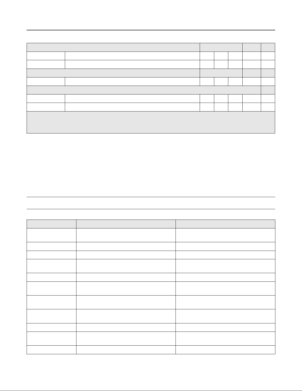
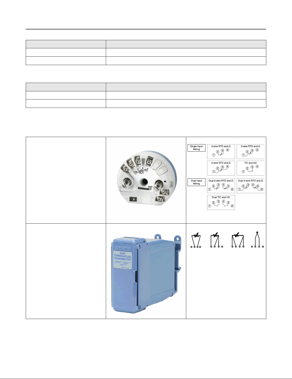
Rosemount 644 Sensor Connections Diagrams
Emerson provides 4-wire sensors for all single element RTDs. You can use these RTDs in 3-wire configurations by leaving the
unneeded leads disconnected and insulated with electrical tape.
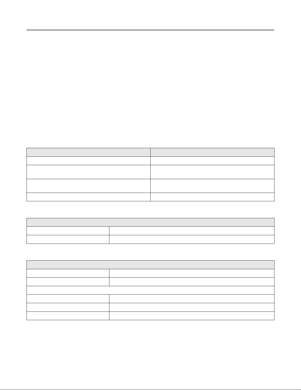
- HART head mount
- HART rail mount
- Fieldbus
- PROFIBUS
19
Page 20
- HART field mount
FOUNDATION Fieldbus specifications
February 2019
Function blocks
Resource block
The resource block contains physical transmitter information including available memory, manufacture identification, device type,
software tag, and unique identification.
Transducer block
The transducer block contains the actual temperature measurement data, including sensor 1 and terminal temperature. It includes
information about sensor type and configuration, engineering units, linearization, reranging, damping, temperature correction,
and diagnostics.
LCD display block
The LCD display block is used to configure the local display, if an LCD display is being used.
Analog input (AI)
■
Processes the measurement and makes it available on the Fieldbus segment.
■
Allows filtering, alarming, and engineering unit changes.
PID block
The transmitter provides control functionality with one PID function block in the transmitter. The PID block can be used to perform
single loop, cascade, or feedforward control in the field.
Block
Resource N/A
Execution time (milliseconds)
Transducer N/A
LCD display block N/A
Analog input 1 45
Analog Input 2 45
PID 1 60
20 www.emerson.com
Page 21

February 2019
Turn-on Time
Performance within specifications in less than 20 seconds after power is applied, when damping value is set to zero seconds.
Status
If self-diagnostics detect a sensor burnout or a transmitter failure, the status of the measurement will be updated accordingly.
Status may also send the AI output to a safe value.
Power Supply
Powered over FOUNDATION Fieldbus with standard Fieldbus power supplies. The transmitter operates between 9.0 and 32.0 Vdc, 12
mA maximum.
Alarms
The AI function block allows the user to configure the alarms to HI-HI, HI, LO, or LO-LO with hysteresis settings.
Backup Link Active Scheduler (LAS)
The transmitter is classified as a device link master, which means it can function as a LAS if the current link master device fails or is
removed from the segment.
The host or other configuration tool is used to download the schedule for the application to the link master device. In the absence
of a primary link master, the transmitter will claim the LAS and provide permanent control for the H1 segment.
FOUNDATION Fieldbus Parameters
Schedule entries
Links 16
Virtual Communications Relationships (VCR) 12
25
PROFIBUS PA specifications
Function blocks
Physical Block
The physical block contains physical transmitter information including manufacturer identification, device type, software tag, and
unique identification.
Transducer Block
The transducer block contains the actual temperature measurement data, including sensor 1 and terminal temperature. It includes
information about sensor type and configuration, engineering units, linearization, re-ranging, damping, temperature correction,
and diagnostics.
Analog Input Block (AI)
The AI block processes the measurement and makes it available on the PROFIBUS segment. Allows filtering, alarming, and
engineering unit changes.
Turn-on time
Performance within specifications in less than 20 seconds after power is applied, when damping value is set to zero seconds.
Power Supply
Powered over PROFIBUS with standard Fieldbus power supplies. The transmitter operates between 9.0 and 32.0 Vdc,12 mA
maximum.
21
Page 22

Load (Ohms)
4−20 mA dc
HART and Analog
operating range
Analog only
operating range
1240
1100
1000
750
500
250
0
10
12.0 Min
18.1 30
42.4
February 2019
Alarms
The AI function block allows the user to configure the alarms to HI-HI, HI, LO, or LO-LO with hysteresis settings.
4–20 mA/HART specifications
Power Supply
External power supply required. Transmitters operate on 12.0 to 42.4 Vdc transmitter terminal voltage (with 250 ohm load, 18.1
Vdc power supply voltage is required). Transmitter power terminals rated to 42.4 Vdc.
Table 8: Load Limitations
Maximum load = 40.8 × (supply voltage - 12.0)
(1)
(1)
Note
HART Communication requires a loop resistance between 250 and 1100 Ohms. Do not communicate with the transmitter when
power is below 12 Vdc at the transmitter terminals.
Temperature Limits
(1)
(2)
22 www.emerson.com
Without transient protection (optional).
Description
With LCD display
Without LCD display –40 to 185 °F
The lower operating and storage temperature limit of a transmitter with option code BR6 is –76 °F (–60 °C)
LCD display may not be readable and display updates will be slower at temperatures below –22 °F (–30 °C).
(2)
Operating limit
–40 to 185 °F
–40 to 85 °C
–40 to 85 °C
(1)
Storage limit
–50 to 185 °F
–45 to 85 °C
–58 to 250 °F
–50 to 120 °C
(1)
Page 23

February 2019
Hardware and Software Failure Mode
The Rosemount 644 features software driven alarm diagnostics and an independent circuit which is designed to provide backup
alarm output if the microprocessor software fails. The alarm direction (HI/LO) is user-selectable using the failure mode switch. If
failure occurs, the position of the switch determines the direction in which the output is driven (HI or LO). The switch feeds into the
digital-to-analog (D/A) converter, which drives the proper alarm output even if the microprocessor fails. The values at which the
transmitter software drives its output in failure mode depends on whether it is configured to standard, custom, or NAMURcompliant (NAMUR recommendation NE 43, June 1997) operation. Table 9 shows the configuration alarm ranges.
Table 9: Available Alarm Range
Units - mA Min Max Rosemount Namur
High alarm 21 23 21.75 21
Low alarm
High saturation 20.5 20.9
Low saturation
(1)
(2)
(3)
(1)
(1)
Requires 0.1 mA gap between low alarm and low saturation values.
Rail mount transmitters have a high saturation max of 0.1 mA less than the high alarm setting, with a max value of 0.1 mA less than the high
alarm max.
Rail mount transmitters have a low saturation min of 0.1 mA greater than the low alarm setting, with a minimum of 0.1 mA greater than the low
alarm min.
3.5 3.75 3.75 3.6
3.7
(3)
(2)
3.9 3.9 3.8
20.5 20.5
Custom Alarm and Saturation Level
Custom factory configuration of alarm and saturation level is available with option code C1 for valid values. These values can also be
configured in the field using a Field Communicator.
Turn-on Time
Performance within specifications in less than six seconds after power is applied, when damping value is set to zero seconds.
External Transient Protection
The Rosemount 470 Transient Protector prevents damage from transients induced by lightning, welding, or heavy electrical
equipment. For more information, refer to the Rosemount 470 Transient Protector Product Data Sheet. Transient Protection
(option code T1)
The transient protector helps to prevent damage to the transmitter from transients induced on the loop wiring by lightning,
welding, heavy electrical equipment, or switch gears. The transient protection electronics are contained in an add-on assembly that
attaches to the standard transmitter terminal block. The external ground lug assembly (code G1) is included with the Transient
Protector. The transient protector has been tested per the following standard:
■
IEEE C62.41-2002 (IEEE 587)/Location Categories B3. 6kV/3kA peak (1.2 50 Ω × Wave 8 20 Ω s Combination Wave) 6kV/0.5kA
peak (100 kHz Ring Wave) EFT, 4kVpeak, 2.5kHz, 5 × 50 nS
■
Loop resistance added by protector: 22 ohms max.
■
Nominal clamping voltages: 90 V (common mode), 77 V (normal mode)
Accuracy example (FOUNDATION Fieldbus and PROFIBUS PA devices)
When using a Pt 100 (α = 0.00385) sensor input:
■
Total accuracy = ±0.15 °C
■
No D/A accuracy effects apply.
23
Page 24

Table 10: Ambient Temperature Effect
Sensor Options Sensor Reference Input Range
(°C)
2-, 3-, 4-wire RTDs
Temperature Effects per 1.0
°C (1.8 °F) Change in
Ambient Temperature
(1) (2)
February 2019
Range D/A Effect
(3)
Pt 100 (α = 0.00385) IEC 751 –200 to 850 0.003 °C (0.0054 °F) Entire
sensor
input range
Pt 200 (α = 0.00385) IEC 751 –200 to 850 0.004 °C (0.0072 °F) Entire
sensor
input range
Pt 500 (α = 0.00385) IEC 751 –200 to 850 0.003 °C (0.0054 °F) Entire
sensor
input range
Pt 1000 (α =
0.00385)
IEC 751 –200 to 300 0.003 °C (0.0054 °F) Entire
sensor
input range
Pt 100 (α =
0.003916)
JIS 1604 –200 to 645 0.003 °C (0.0054 °F) Entire
sensor
input range
Pt 200 (α =
0.003916)
JIS 1604 –200 to 645 0.004 °C (0.0072 °F) Entire
sensor
input range
Ni 120 Edison Curve No. 7 –70 to 300 0.003 °C (0.0054 °F) Entire
sensor
input range
Cu 10 Edison Copper
Winding No. 15
–50 to 250 0.03 °C (0.054 °F) Entire
sensor
input range
0.001% of span
0.001% of span
0.001% of span
0.001% of span
0.001% of span
0.001% of span
0.001% of span
0.001% of span
Pt 50 (α = 0.00391) GOST 6651-94 –200 to 550 0.004 °C (0.0072 °F) Entire
0.001% of span
sensor
input range
Pt 100 (α = 0.00391) GOST 6651-94 –200 to 550 0.002 °C (0.0036 °F) Entire
0.001% of span
sensor
input range
Cu 50 (α = 0.00426) GOST 6651-94 –50 to 200 0.008 °C (0.0144 °F) Entire
0.001% of span
sensor
input range
Cu 50 (α = 0.00428) GOST 6651-94 –185 to 200 0.008 °C (0.0144 °F) Entire
0.001% of span
sensor
input range
Cu 100 (α =
0.00426)
GOST 6651-94 –50 to 200 0.004 °C (0.0072 °F) Entire
sensor
0.001% of span
input range
Cu 100 (α =
0.00428)
GOST 6651-94 –185 to 200 0.004 °C (0.0072 °F) Entire
sensor
0.001% of span
input range
Thermocouples
24 www.emerson.com
Page 25

February 2019
Table 10: Ambient Temperature Effect (continued)
Sensor Options Sensor Reference Input Range
(°C)
Temperature Effects per 1.0
°C (1.8 °F) Change in
Ambient Temperature
(1) (2)
Range D/A Effect
(3)
Type B NIST Monograph 175,
IEC 584
Type E NIST Monograph 175,
IEC 584
Type J NIST Monograph 175,
IEC 584
Type K NIST Monograph 175,
IEC 584
Type N NIST Monograph 175,
IEC 584
Type R NIST Monograph 175,
IEC 584
Type S NIST Monograph 175,
IEC 584
Type T NIST Monograph 175,
IEC 584
100 to 1820 0.014 °C T ≥ 1000 °C 0.001% of span
0.032 °C – (0.0025% of (T –
300))
0.054 °C – (0.011% of (T –
100))
300 °C ≤ T <
1000 °C
100 °C ≤ T <
300 °C
0.001% of span
0.001% of span
–200 to 1000 0.005 °C + (0.00043% of T) All 0.001% of span
–180 to 760 0.0054 °C + (0.00029%of T) T ≥ 0 °C 0.001% of span
0.0054 °C + (0.0025% of
T < 0 °C 0.001% of span
absolute value T)
–180 to 1372 0.0061 °C + (0.00054% of T) T ≥ 0 °C 0.001% of span
0.0061 °C + (0.0025% of
T < 0 °C 0.001% of span
absolute value T)
–200 to 1300 0.0068 °C + (0.00036% of T) All 0.001% of span
0 to 1768 0.016 °C T ≥ 200 °C 0.001% of span
0.023 °C – (0.0036% of T) T < 200 °C 0.001% of span
0 to 1768 0.016 °C T ≥ 200 °C 0.001% of span
0.023 °C – (0.0036% of T) T < 200 °C 0.001% of span
–200 to 400 0.0064 °C T ≥ 0 °C 0.001% of span
0.0064 °C +(0.0043% of
T < 0 °C 0.001% of span
absolute value T)
DIN Type L DIN 43710 –200 to 900 0.0054 °C + (0.00029% of T) T ≥ 0 °C 0.001% of span
0.0054 °C + (0.0025% of
T < 0 °C 0.001% of span
absolute value T)
DIN Type U DIN 43710 –200 to 600 0.0064 °C T ≥ 0 °C 0.001% of span
0.0064 °C + (0.0043% of
T < 0 °C 0.001% of span
absolute value T)
Type W5Re/W26Re ASTM E 988-96 0 to 2000 0.016 °C T ≥ 200 °C 0.001% of span
0.023 °C – (0.0036% of T) T < 200 °C 0.001% of span
GOST Type L GOST R 8.585-2001 -200 to 800 0.007 °C T ≥ 0 °C 0.001% of span
0.007 °C + (0.003% of
T < 0 °C 0.001% of span
absolute value T)
Other input types
Millivolt input –10 to 100 mV 0.0005 mV Entire
0.001% of span
sensor
input range
25
Page 26

Table 10: Ambient Temperature Effect (continued)
Sensor Options Sensor Reference Input Range
(°C)
Temperature Effects per 1.0
°C (1.8 °F) Change in
Ambient Temperature
(1) (2)
February 2019
Range D/A Effect
(3)
2-, 3-, 4-wire Ohm 0 to 2000 Ω 0.0084 Ω Entire
0.001% of span
sensor
input range
Change in ambient is with reference to the calibration temperature of the transmitter 68 °F (20 °C) from factory.
(1)
Ambient temperature effect specification valid over minimum temperature span of 28 °C (50 °F).
(2)
Does not apply to FOUNDATION Fieldbus.
(3)
Temperature Effects Example (HART devices)
When using a Pt 100 (α = 0.00385) sensor input with a 0–100 °C span at 30 °C ambient temperature:
■
Digital temperature effects: 0.003 °C × (30 - 20) = 0.03 °C
■
D/A effects: [0.001% of 100] × (30 – 20) = 0.01 °C
■
Worst case error: Digital + D/A + Digital Temperature Effects + D/A Effects = 0.15 °C + 0.03 °C + 0.03 °C + 0.01 °C = 0.22 °C
■
Total probable error:
= 0.16 °C
Temperature Effects Examples (FOUNDATION Fieldbus devices and PROFIBUS PA)
When using a Pt 100 (α = 0.00385) sensor input at 30 °C span at 30 °C ambient temperature:
■
Digital temperature effects: 0.003 °C × (30 – 20) = 0.03 °C
■
D/A effects: No D/A effects apply.
■
Worst case error: Digital + Digital Temperature Effects = 0.15 °C + 0.03 °C = 0.18 °C
■
Total probable error: = 0.153 °C
Table 11: Transmitter Accuracy when Ordered with Option Code P8
Sensor Options Sensor
2-, 3-, 4-wire RTDs °C °F °C °F °C °F
Pt 100 (α =
Reference
IEC 751 –200 to
0.00385)
Pt 200 (α =
IEC 751 –200 to
0.00385)
Pt 500 (α =
IEC 751 –200 to
0.00385)
Pt 1000 (α =
IEC 751 –200 to
0.00385)
Pt 100 (α =
JIS 1604 –200 to
0.003916)
Pt 200 (α =
JIS 1604 –200 to
0.003916)
Ni 120 Edison Curve
No. 7
Input Ranges Minimum Span
850
850
850
300
645
645
–70 to
300
–328 to
1562
–328 to
1562
–328 to
1562
–328 to
572
–328 to
1193
–328 to
1193
–94 to
572
10 18 ± 0.10 ± 0.18 ±0.02% of span
10 18 ± 0.22 ± 0.40 ±0.02% of span
10 18 ± 0.14 ± 0.25 ±0.02% of span
10 18 ± 0.10 ± 0.18 ±0.02% of span
10 18 ± 0.10 ± 0.18 ±0.02% of span
10 18 ± 0.22 ± 0.40 ±0.02% of span
10 18 ± 0.08 ± 0.14 ±0.02% of span
(1)
Digital Accuracy
(2)
D/A Accuracy
(3) (4)
26 www.emerson.com
Page 27

February 2019
Table 11: Transmitter Accuracy when Ordered with Option Code P8 (continued)
Cu 10 Edison Copper
Winding No. 15
–50 to
250
Pt 50 (α=0.00391) GOST 6651-94 –200 to
550
Pt 100 (α=0.00391) GOST 6651-94 –200 to
550
Cu 50
(α=0.00426)
Cu 50
(α=0.00428)
Cu 100
(α=0.00426)
Cu 100
(α=0.00428)
Thermocouples
Type B
(6)
GOST 6651-94 –50 to
GOST 6651-94 –185 to
GOST 6651-94 –50 to
GOST 6651-94 –185 to
(5)
NIST
Monograph
200
200
200
200
100 to
1820
175, IEC 584
Type E NIST
Monograph
–200 to
1000
175, IEC 584
–58 to
482
–328 to
1022
–328 to
1022
–58 to
392
–301 to
392
–58 to
392
–301 to
392
212 to
3308
–328 to
1832
10 18 ±1.00 ± 1.80 ±0.02% of span
10 18 ±0.20 ±0.36 ±0.02% of span
10 18 ±0.10 ±0.18 ±0.02% of span
10 18 ±0.20 ±0.36 ±0.02% of span
10 18 ±0.34 ±0.61 ±0.02% of span
10 18 ±0.17 ±0.31 ±0.02% of span
10 18 ±0.17 ±0.31 ±0.02% of span
25 45 ± 0.75 ± 1.35 ±0.02% of span
25 45 ± 0.20 ± 0.36 ±0.02% of span
Type J NIST
Monograph
–180 to
760
175, IEC 584
Type K
(7)
NIST
Monograph
–180 to
1372
175, IEC 584
Type N NIST
Monograph
–200 to
1300
175, IEC 584
Type R NIST
0 to 1768 32 to
Monograph
175, IEC 584
Type S NIST
0 to 1768 32 to
Monograph
175, IEC 584
Type T NIST
Monograph
–200 to
400
175, IEC 584
DIN Type L DIN 43710 –200 to
900
DIN Type U DIN 43710 –200 to
600
Type W5Re/
ASTM E 988-96 0 to 2000 32 to
W26Re
–292 to
1400
–292 to
2501
–328 to
2372
3214
3214
–328 to
752
–328 to
1652
–328 to
1112
3632
25 45 ± 0.25 ± 0.45 ±0.02% of span
25 45 ± 0.25 ± 0.45 ±0.02% of span
25 45 ± 0.40 ± 0.72 ±0.02% of span
25 45 ± 0.60 ± 1.08 ±0.02% of span
25 45 ± 0.50 ± 0.90 ±0.02% of span
25 45 ± 0.25 ± 0.45 ±0.02% of span
25 45 ± 0.35 ± 0.63 ±0.02% of span
25 45 ± 0.35 ± 0.63 ±0.02% of span
25 45 ± 0.70 ± 1.26 ±0.02% of span
27
Page 28

Table 11: Transmitter Accuracy when Ordered with Option Code P8 (continued)
February 2019
GOST Type L GOST R
8.585-2001
–200 to
800
–392 to
1472
25 45 ± 0.25 ± 0.45 ±0.02% of span
Other input types
Millivolt input –10 to 100 mV 3 mV ±0.015 mV ±0.02% of span
2-, 3-, 4-wire Ohm input 0 to 2000 ohms 20 ohm ±0.35 ohm ±0.02% of span
No minimum or maximum span restrictions within the input ranges. Recommended minimum span will hold noise within accuracy specification
(1)
with damping at zero seconds.
Digital accuracy: Digital output can be accessed by the Field Communicator.
(2)
Total Analog accuracy is the sum of digital and D/A accuracies.
(3)
Applies to HART/4–20 mA devices.
(4)
Total digital accuracy for thermocouple measurement: sum of digital accuracy +0.25 °C (0.45 °F) (cold junction accuracy).
(5)
Digital accuracy for NIST Type B is ±3.0 °C (±5.4 °F) from 100 to 300 °C (212 to 572 °F).
(6)
Digital accuracy for NIST Type K is ±0.7 °C (±1.3 °F) from –180 to –90 °C (–292 to –130 °F).
(7)
Reference accuracy example (HART only)
When using a Pt 100 (α = 0.00385) sensor input with a 0 to 100 °C span: Digital Accuracy would be ±0.10 °C, D/A accuracy would be
±0.02% of 100 °C or ±0.02 °C, Total = ±0.12 °C.
Differential capability exists between any two sensor types (dual-sensor option)
For all differential configurations, the input range is X to Y where:
■
X = Sensor 1 minimum – Sensor 2 maximum and
■
Y = Sensor 1 maximum – Sensor 2 minimum
28 www.emerson.com
Page 29

33 (1.3)
60 (2.4)
59 (2.3)
24 (.96)
C
B
A
E
D
31 (1.2)
59 (2.3)
D
B
C
F
E
60 (2.4)
33 (1.3)
23 (1.0)
59 (2.3)
26 (1.0)
February 2019
Dimensional drawings
Figure 1: Rosemount 644H (DIN A Head Mount)
HART device shown with captivated screw terminals
FOUNDATION Fieldbus and PROFIBUS device shown with Standard
Compression Screw Terminals
A. Failure mode switch
B. Meter connector
C. Sensor terminals
Dimensions are in millimeters (inches).
D. Communication terminals
E. Power terminals
F. Simulation switch
29
Page 30

Figure 2: Rosemount 644 Field Mount
Transmitter exploded view
February 2019
Display compartment Terminal compartment
A. Nameplate
B. Cover
C. Housing with electronics module
D. LCD display
E. Display cover
Dimensions are in millimeters (inches).
F. Failure mode switch
G. Meter connector
H. Sensor terminals
I. Communication terminals
J. Power terminals
30 www.emerson.com
Page 31

A
B
C
February 2019
Figure 3: Rosemount 644 Rail Mount
A. Sensor terminals
B. Failure mode switch
C. Power terminals
Dimensions are in millimeters (inches).
Figure 4: Mounting kits for Rosemount 644H
Rosemount 644R Rail and Walls Clips
A. Top hat rail grooves
B. G-rail grooves
C. Screw holes for mounting to a wall
31
Page 32

Figure 5: Rosemount 644H Rail Clips
D
E
F
D
E
F
G-Rail (asymmetric) Top Hat Rail (symmetric)
Note
Kit (part number 00644-5301-0010) includes mounting hardware and both types of rail kits.
February 2019
D. Mounting hardware
E. Transmitter
F. Rail clip
32 www.emerson.com
Page 33

A
B
C
D
112
(4.4)
96
(3.8)
95
(3.7)
75
(2.9)
103 (4.0) with LCD Display
104
(4.0)
78
(3.0)
128 (5.0) with LCD Display
100
(3.9)
February 2019
G-Rail (asymmetric) Top Hat Rail (symmetric)
Note
Part number 03044-4103-0001.
Threaded-Sensor Universal Head (Option code J5, J6, J7 or J8) DIN Style Sensor Connection Head (Option code R1, R2, R3
or R4)
33
Page 34

90.9
(3.6)
85.9
(3.4)
102.6 (4.0)
with LCD cover
B
A
108
(4.3)
102
(4.0)
February 2019
Threaded-Sensor Universal Head (Option code J5, J6, J7 or J8) DIN Style Sensor Connection Head (Option code R1, R2, R3
or R4)
A. Standard cover
B. Display cover
C. LCD display
D. SST “U” Bolt Mounting, 2-in. pipe (shipped with each connection head ordered with assembly option XA)
Dimensions are in millimeters (inches).
Threaded Sensor Universal Head, 3-conduit (Option code J1 or J2)
A. Standard cover
B. Display cover
Dimensions are in millimeters (inches).
34 www.emerson.com
Page 35

59
(2.3)
33
(1.3)
24
(0.96)
68
(2.7)
40
(1.6)
31
(1.2)
F
F
D
G
B
A
C
33
(1.3)
38
(1.5)
67
(2.7)
59
(2.3)
26
(1.0)
A
E
C
D
F
G
F
February 2019
HART device shown with transient protector (Option code
T1)
FOUNDATION Fieldbus device shown with transient protector
(Option code T1)
Note: Option code T1 requires the use of J1, J2, J3 or J4 enclosure option.
A. Sensor terminals
B. Failure mode switch
C. Meter connector
D. Power terminals
E. Simulation switch
F. Transient protector
G. Ground wire
Dimensions are in millimeters (inches).
35
Page 36

Accessory dimensional drawings
A B C
80
(3.1)
76
(3.0)
70
(2.8)
24
(0.96)
45
(1.8)
25
(1.0)
28 (1.1)
33 (1.3)
D B C
70
(2.8)
61
(2.4)
47
(1.9)
74
(2.9)
25
(1.0)
45
(1.8)
33 (1.3)
76
(3.0)
28 (1.1)
B
A
C
B
D
E
Figure 6: Stainless Steel Housing for Biotechnology, Pharmaceutical Industries, and Sanitary Applications
Sanitary housing (option code S1, S2, S3, S4)
Standard cover LCD display cover
A. Standard cover
B. O-ring
C. Housing
D. LCD display cover
Dimensions are in millimeters (inches).
February 2019
Figure 7: Display
LCD display
Enhanced display with LOI
36 www.emerson.com
Page 37

60
(2.4)
30
(1.2)
25
(1.0)
100
(3.9)
25
(1.0)
25
(1.0)
2
(0.065)
112
(4.4)
76
(3.0)
4
(0.14)
February 2019
A. LCD display
B. Rosemount 644 Transmitter
D. LCD display with LOI
E. Display rotation screws
C. Display rotation
Dimensions are in millimeters (inches).
Figure 8: Optional Mounting
Optional Transmitter Mounting Brackets
Option Code B4 Bracket for enclosures j1, j2, J3, and J4 Option code B4 bracket for enclosures D1 and D2
Dimensions are in millimeters (inches).
Option Code B5 Bracket for enclosures j1, j2, J3, and J4 Option code B5 bracket for enclosures D1 and D2
37
Page 38

60
(2.4)
175
(6.9)
71
(2.8)
156
(6.2)
71
(2.8)
60
(2.4)
19
(0.75)
19
(0.75)
2
(0.083)
February 2019
Dimensions are in millimeters (inches).
38 www.emerson.com
Page 39

February 2019
Configuration
Transmitter configuration
The transmitter is available with standard configuration setting for either HART (see Standard HART configuration), FOUNDATION
Fieldbus (see Standard FOUNDATION Fieldbus configuration) or PROFIBUS PA (see Standard PROFIBUS PA configuration). The
configuration settings and block configuration may be changed in the field with Emerson DeltaV™, AMS Suite, handheld Field
communicator or other host or configuration tool.
Standard HART configuration
Unless specified, the transmitter will be shipped as follows:
Sensor type RTD, Pt 100 (α=0.00385, 4-wire)
4 mA value 0 °C
20 mA value 100 °C
Output Linear with temperature
Saturation levels 3.9/20.5 mA
Damping 5 seconds
Line voltage filter 50 Hz
Alarm High (21.75 mA)
LCD display (when installed) Engineering units and mA
Tag See Tagging.
Standard FOUNDATION Fieldbus configuration
Unless otherwise specified, the transmitter will be shipped as follows:
Sensor type: RTD, Pt 100 (α=0.00385, 4-wire)
Damping: 5 seconds
Units of measurement: °C
Line voltage filter: 50 Hz
Software tag: See Tagging
Function block tags:
■
Resource block: Resource
■
Transducer block: Transducer
■
LCD display block: LCD display
■
Analog input blocks: AI 1300, AI 1400
PID block: PID 1500
Alarm limits of AI 1300, AI 1400
■
HI-HI: Infinity
■
HI: Infinity
■
LO: Infinity
■
LO-LO: Infinity
Local display (when installed): Engineering units of temperature
39
Page 40

Figure 9: Standard Block Configuration
■
T1= Sensor Temperature
■
Tb= Terminal Temperature
Final stations
AI blocks are scheduled for one second. AI blocks are linked as shown above.
Standard PROFIBUS PA configuration
Unless specified, the transmitter will be shipped as follows:
Device address: 126
Sensor Type: RTD, Pt 100 (α=0.00385, 4-wire)
February 2019
Damping: 5 seconds
Units of measurement: °C
Line voltage filter: 50 Hz
Software tag: see Tagging.
Alarm limits:
■
HI-HI: Infinity
■
HI: Infinity
■
LO: - Infinity
■
LO-LO: Infinity
Local display (when installed): Engineering units of temperature
Custom configuration
Custom configurations are to be specified when ordering. This configuration must be the same for all sensors. The following table
lists the necessary requirements to specify a custom configuration:
40 www.emerson.com
Page 41

February 2019
Option code Customization available
H
C1: Factory Configuration Data (CDS required)
A
R
Also needs option code:
T
P
r
o
t
o
c
o
l
...M4 or M5
■
Date: day/month/year
■
Descriptor: Eight alphanumeric characters
■
Message: 32 alphanumeric characters
■
Hardware tag: 13 characters
■
Software tag: Eight characters
■
Sensor type and connection
■
Measurement range and units
■
Damping value
■
Failure mode: High or Low
■
Hot Backup: Mode and PV
■
Sensor drift alert: Mode, limit and units
■
Display configuration: Select what will be shown on the
LCD display.
...DC
...DC
C2:Transmitter – sensor matching
A1, CN, or C8: Alarm level configuration
Q4: Three-point calibration with certificate
C4: Five-point calibration
■
Custom alarm and saturation levels: Choose custom High
and Low alarm and saturation levels.
■
Security information: Write protection, HART Lock and LOI
Password
■
The transmitters are designed to accept Callendar-Van
Dusen constants from a calibrated RTD. Using these
constants, the transmitter generates a custom curve to
match the sensor-specific curve. Specify a Rosemount
Series 65, 65, or 78 RTD sensor on the order with a special
characterization curve (V or X8Q4 option). These
constants will be programmed into the transmitter with
this option.
■
A1: NAMUR Alarm and saturation levels, with high alarm
configured
■
CN: NAMUR Alarm and saturation levels, with low alarm
configured
■
C8: Low alarm (standard Rosemount alarm and saturation
values)
■
Calibration certificate. Three-point calibration at 0, 50, and
100% with certificate.
■
Will include five-point calibration at 0, 25, 50, 75, and
100% analog and digital output points. Use with
Calibration Certificate Q4.
HR7: HART Revision configuration
■
Your Rosemount 644 head mount and field mount are
HART revision selectable. Order the HR7 code to configure
your device to operate in HART Revision 7 mode. Your
device is also configurable in the field. Refer to the
Rosemount 644 Quick Start Guide or Reference Manual for
more instructions.
■
Long software tag: 32 characters
41
Page 42

Option code Requirements/specification
February 2019
F
C1: Factory configuration data
O
(CDS required)
U
C2: Transmitter – sensor matching The transmitters are designed to accept Callendar-Van Dusen
N
D
A
T
I
O
N
F
C4: Five-point calibration Will include five-point calibration at 0, 25, 50, 75, and 100%
i
e
l
d
Q4: Three-point calibration with certificate Calibration certificate. Three-point calibration with certificate.
b
u
s
Option code Requirements/specification
P
C1: Factory Configuration Data
R
(CDS required)
O
C2: Transmitter – Sensor Matching The transmitters are designed to accept Callendar-Van Dusen
F
I
B
U
S
P
A
C4: Five-point calibration Will include five-point calibration at 0, 25, 50, 75, and 100%
Date: day/month/year Descriptor: 16 alphanumeric characters
Message: 32 alphanumeric characters
constants from a calibrated RTD. Using these constants, the
transmitter generates a custom curve to match the sensorspecific curve. Specify a Series 65, 65, or 78 RTD sensor on the
order with a special characterization curve (V or X8Q4 option).
These constants will be programmed into the transmitter with
this option.
analog and digital output points. Use with Calibration
Certificate Q4.
Date: day/month/year Descriptor: 16 alphanumeric characters
Message: 32 alphanumeric characters
constants from a calibrated RTD. Using these constants, the
transmitter generates a custom curve to match the sensorspecific curve. Specify a Series 65, or 78 RTD sensor on the
order with a special characterization curve (V or X8Q4 option).
These constants will be programmed into the transmitter with
this option.
analog and digital output points. Use with Calibration
Certificate Q4.
Q4: Three-point calibration with certificate Calibration certificate. Three-point calibration with certificate.
Specifications and reference data for Rosemount 644 HART (Device Revision 7 or Previous)
Functional specifications
Inputs
User-selectable; sensor terminals rated to 42.4 Vdc. See Accuracy example (FOUNDATION Fieldbus and PROFIBUS PA devices).
Output
Single two-wire device with either 4–20 mA/HART, linear with temperature or input; or completely digital outputs with FOUNDATION
Fieldbus communication (ITK 5.01 compliant), or PROFIBUS PA (compliant with profile 3.02).
Isolation
Input/output isolation tested to 620 Vrms.
42 www.emerson.com
Page 43

February 2019
Local display options
LCD
display
LCD
display
with LOI
An optional 11 digit, two-line integral LCD display operates with a floating or fixed decimal point. It displays
engineering units (°F, °C, °R, K, Ohms and mV), mA, and percent of range. The display can be configured to alternate
between selected display options. Display settings are pre-configured at the factory according to the standard
transmitter configuration. They can be re-configured in the field using either HART, FOUNDATION Fieldbus, or
PROFIBUS PA communications.
An optional 14-digit, two-line integral LCD display operates with a floating or fixed decimal point. The LOI includes
all features and functionality available in the regular display with an added two-button configuration capability
directly at the display interface. The LOI also has optional password protection for secure operations. The LOI is only
available on the Rosemount 644 HART head mount and field mount transmitters.
For more information on the LOI configuration options or further functionality that the LOI offers, see the
Rosemount 644 Temperature Transmitter Reference Manual.
Humidity Limits
0–95 percent relative humidity
Update Time
≤0.5 second per sensor
Accuracy(default configuration) PT 100
HART Standard: ±0.15 °C
HART Enhanced: ±0.1 °C
FOUNDATION Fieldbus: ±0.15 °C
PROFIBUS PA: ±0.15 °C
Physical specifications
Material selection
Emerson provides a variety of Rosemount product with various product options and configurations including materials of
construction that can be expected to perform well in a wide range of applications. The Rosemount product information presented
is intended as a guide for the purchaser to make an appropriate selection for the application. It is the purchaser’s sole responsibility
to make a careful analysis of all process parameters (such as all chemical components, temperature, pressure, flow rate, abrasives,
contaminants, etc.), when specifying product, materials, options and components for the particular application. Emerson is not in a
position to evaluate or guarantee the compatibility of the process fluid or other process parameters with the product, options,
configuration or materials of construction selected.
Conformance to specifications (±3σ [Sigma])
Technology leadership, advanced manufacturing techniques, and statistical process control ensure specification conformance to at
least ±3σ.
Electrical connections
Rosemount model
644 head mount (HART) Captivated screw terminals permanently fixed to terminal block
644 head mount (FOUNDATION Fieldbus/PROFIBUS) Compression screw terminals permanently fixed to the terminal
644 field mount (HART) Captivated screw terminals permanently fixed to the terminal
644 rail mount (HART) Compression screw permanently fixed to front panel
Power and Sensor Terminals
block
block
43
Page 44

February 2019
Field Communicator Connections
Communication Terminals
Rosemount 644 head/field mount Clips permanently fixed to terminal block
Rosemount 644 rail mount Clips permanently fixed to front panel
Materials of Construction
Electronics Housing and Terminal Block
Rosemount 644 head/ field mount GE polyphenylene oxide glass reinforced GFN -2 or -3
Rosemount 644 rail mount Polycarbonate
Enclosure (Options J1, J2, J5, J6, R1, R2, D1, and D2)
Housing Low-copper aluminum
Paint Polyurethane
Cover O-ring Buna-N
Materials of Construction (Stainless Steel Housing for Biotechnology, Pharmaceutical Industries, and Sanitary
Applications)
Housing and standard meter cover
■
316 SST
Cover O-ring
■
Buna-N
Mounting
The Rosemount 644R attaches directly to a wall or a DIN rail. The Rosemount 644H installs in a connection head or universal head
mounted directly on a sensor assembly, apart from a sensor assembly using a universal head, or to a DIN rail using an optional
mounting clip.
Special Mounting Considerations
See for the special hardware that is available to:
■
Mount a Rosemount 644H to a DIN rail. (see Dimensional drawings)
■
Retrofit a new Rosemount 644H to replace an existing Rosemount 644H Transmitter in an existing threaded sensor
connection head. (see Table 3)
Weight
Code
644H HART, head mount transmitter 78 g (2.75 oz)
644H FOUNDATION Fieldbus, head mount transmitter 92 g (3.25 oz)
644H PROFIBUS PA, head mount transmitter 92 g (3.25 oz)
644R HART, rail mount transmitter 174 g (6.14 oz)
M5 LCD display 34 g (1.2 oz)
M4 LCD display with local operator interface 34 g (1.2 oz)
J1, J2 Universal head, 3-conduits, standard cover 718 g (25.33oz)
Options Weight
44 www.emerson.com
Page 45

February 2019
Code Options Weight
J1, J2 Universal head, 3-conduits, meter cover 826 g (29.14oz)
J3, J4 Cast SST universal head, 3-conduits, standard cover 2073 g (73.12oz)
J3, J4 Cast SST universal head, 3-conduits, meter cover 2148 g (75.77oz)
J5, J6 Aluminum 2-conduits, universal head, standard cover 520g (18.43oz)
J5, J6 Aluminum 2-conduits, universal head, meter cover 604 g (21.27oz)
J7, J8 Cast SST universal head 2-conduits, standard, cover 577 g (20.35oz)
J7, J8 Cast SST universal head 2-conduits, meter cover 667 g (23.53oz)
R1, R2 Aluminum connection head, standard cover 523 g (18.45 oz)
R1, R2 Aluminum connection head, meter cover 618 g (21.79 oz)
R3, R4 Cast SST connection head, standard cover 1615 g (56.97 oz)
R3, R4 Cast SST connection head, meter cover 1747 g (61.62 oz)
D1, D2 HART, field mount transmitter, aluminum housing, meter
cover, standard cover
1128 g (39.79 oz)
Weight (Stainless Steel Housing for Biotechnology, Pharmaceutical Industries, and Sanitary Applications)
Option Code Standard Cover Meter Cover
S1 840 g (27 oz) 995 g (32 oz)
S2 840 g (27 oz) 995 g (32 oz)
S3 840 g (27 oz) 995 g (32 oz)
S4 840 g (27 oz) 995 g (32 oz)
Enclosure Ratings (Rosemount 644H/F)
All available enclosures are Type 4X, IP66, and IP68.
Sanitary Housing Surface
Surface finish is polished to 32 RMA. Laser etched product marking on housing and standard covers.
Performance specifications
ElectroMagnetic Compatibility (EMC) NAMUR NE 21 Standard
The Rosemount 644H HART meets the requirements for NAMUR NE 21 Rating.
Susceptibility
ESD
Radiated
Burst
Parameter Influence
■
6 kV contact discharge
■
8 kV air discharge
■
80 – 1000 MHz at 10 V/m AM < 1.0%
■
1 kV for I.O. None
None
45
Page 46

Susceptibility Parameter Influence
Surge
■
0.5 kV line–line
■
1 kV line–ground (I.O. tool)
None
February 2019
Conducted
■
10 kHz to 80 MHz at 10 V < 1.0%
CE Electromagnetic Compatibility Compliance Testing
The Rosemount 644 is compliant with Directive 2004/108/EC. Meets the criteria under IEC 61326:2006, IEC 61326-2-3:2006.
Power Supply Effect
Less than ±0.005 percent of span per volt
Stability
RTDs and thermocouples have a stability of ±0.15 percent of output reading or 0.15 °C (whichever is greater) for 24 months.
When ordered with the P8 option code:
■
RTDs: ±0.25 percent of reading or 0.25 °C, whichever is greater, for five years
■
Thermocouples: ±0.5 percent of reading or 0.5 °C, whichever is greater, for five years
Self Calibration
The analog-to-digital measurement circuitry automatically self-calibrates for each temperature update by comparing the dynamic
measurement to extremely stable and accurate internal reference elements.
Vibration Effect
The Rosemount 644 HART head mount and field mount are tested to the following specifications with no effect on performance
per IEC 60770-1, 2010:
Frequency
10 to 60 Hz 0.35 mm displacement
60 to 1000 Hz 5g (50 m/s2) peak acceleration
The Rosemount 644 Fieldbus and PROFIBUS are tested to the following specifications with no effect on performance per IEC
60770-1: 1999:
Frequency
10 to 60 Hz 0.21 mm displacement
60 to 2000 Hz 3 g peak acceleration
Vibration
Vibration
Rosemount 644 Sensor Connections Diagrams
Emerson provides 4-wire sensors for all single element RTDs. You can use these RTDs in 3-wire configurations by leaving the
unneeded leads disconnected and insulated with electrical tape.
46 www.emerson.com
Page 47

–
+
+
–
1
2-wire
RTD and Ω
3-wire
RTD and Ω*
4-wire
RTD and Ω
T/C
and mV
2 3 4 4 4 43 3 32 2 21 1 1
+
_
February 2019
- HART head mount
- HART rail mount
- Fieldbus
- PROFIBUS
- HART field mount
47
Page 48

Load (Ohms)
4−20 mA dc
HART and Analog
operating range
Analog only
operating range
1240
1100
1000
750
500
250
0
10
12.0 Min
18.1 30
42.4
February 2019
4–20 mA/HART specifications
Power Supply
External power supply required. Transmitters operate on 12.0 to 42.4 Vdc transmitter terminal voltage (with 250 ohm load, 18.1
Vdc power supply voltage is required). Transmitter power terminals rated to 42.4 Vdc.
Load limitations
Maximum Load = 40.8 × (Supply Voltage - 12.0)
(1)
(1)
Note
HART Communication requires a loop resistance between 250 and 1100 Ohms. Do not communicate with the transmitter when
power is below 12 Vdc at the transmitter terminals.
Temperature Limits
(1)
(2)
Hardware and Software Failure Mode
The Rosemount 644 Transmitter features software driven alarm diagnostics and an independent circuit which is designed to
provide backup alarm output if the microprocessor software fails. The alarm direction (HI/LO) is user-selectable using the failure
mode switch. If failure occurs, the position of the switch determines the direction in which the output is driven (HI or LO). The
switch feeds into the digital-to-analog (D/A) converter, which drives the proper alarm output even if the microprocessor fails. The
48 www.emerson.com
Without transient protection(optional).
Descriptions
With LCD display
Without LCD display –40 to 185 °F
The lower operating and storage temperature limit of a transmitter with option code BR6 is –76 °F (–60 °C).
LCD display may not be readable and display updates will be slower at temperatures below –22 °F (–30 °C).
(2)
Operating Limit
–40 to 185 °F
–40 to 85 °C
–40 to 85 °C
(1)
Storage Limit
–50 to 185 °F
–45 to 85 °C
–60 to 250 °F
–50 to 120 °C
(1)
Page 49

February 2019
values at which the transmitter software drives its output in failure mode depends on whether it is configured to standard, custom,
or NAMUR-compliant (NAMUR recommendation NE 43, June 1997) operation. Table 12 shows the configuration alarm ranges.
Custom Alarm and Saturation Level
Table 12: Available Alarm Range Measured in mA
Standard NAMUR- NE 43 Compliant
Linear output 3.9 ≤ I
Fail high 21.75 ≤ I ≤ 23 21.5 ≤ I ≤ 23
Fail low 3.5 ≤ I ≤ 3.75 3.5 ≤ I ≤ 3.6
I = Process Variable (current output).
(1)
Custom factory configuration of alarm and saturation level is available with option code C1 for valid values. These values can also be
configured in the field using a Field Communicator.
(1)
£ 20.5 3.8 ≤ I ≤ 20.5
Turn-on Time
Performance within specifications in less than six seconds after power is applied, when damping value is set to zero seconds.
Transient Protection
The Rosemount 470 Transient Protector prevents damage from transients induced by lightning, welding, or heavy electrical
equipment. For more information, refer to the Rosemount 470 Transient Protector Product Data Sheet.
Accuracy
For complete accuracy tables by sensor type, see Table 1.
Configuration
For standard and custom configuration information, see Configuration.
49
Page 50

February 2019
Product Certifications
Rev 3.0
European Directive Information
A copy of the EU Declaration of Conformity can be found at the end of the Quick Start Guide. The most recent revision of the EU
Declaration of Conformity can be found at Emerson.com/Rosemount.
Ordinary Location Certification
As standard, the transmitter has been examined and tested to determine that the design meets the basic electrical, mechanical,
and fire protection requirements by a nationally recognized test laboratory (NRTL) as accredited by the Federal Occupational Safety
and Health Administration (OSHA).
North America
The US National Electrical Code® (NEC) and the Canadian Electrical Code (CEC) permit the use of Division marked equipment in
Zones and Zone marked equipment in Divisions. The markings must be suitable for the area classification, gas, and temperature
class. This information is clearly defined in the respective codes.
USA
E5
Certificate:
Standards:
Markings:
Certificate:
Standards:
Markings:
I5 USA Intrinsic Safety and Non-Incendive
Certificate:
Standards:
Markings:
USA Explosionproof, Non-Incendive, Dust-Ignitionproof
[XP & DIP]: 3006278; [NI]: 3008880 & 3044581
FM Class 3600: 2011, FM Class 3615: 2006, FM Class 3616: 2011, FM Class 3810: 2005, ANSI/NEMA®-250: 2003,
ANSI/IEC 60529: 2004
XP CL I, DIV 1, GP B, C, D; DIP CL II/III, DIV 1, GP E, F, G; T5 (–50 °C ≤ Ta ≤ +85 °C); Type 4X; IP66; See I5 description for
Non-Incendive markings.
1091070
FM Class 3600: 2011, FM Class 3615: 2006, FM Class 3616: 2011, UL Std. No. 61010-1-12, UL Std. No. 50E, CAN/CSA
C22.2 No. 60529-05
XP CL I, DIV 1, GP B, C, D; DIP CL II / III, DIV 1, GP E, F, G; T5 (–50 °C ≤ Ta ≤ +85 °C); Type 4X; IP66;
3008880 [Headmount Fieldbus/PROFIBUS®, Railmount HART]
FM Class 3600: 2011, FM Class 3610: 2010, FM Class 3611: 2004, FM Class 3810: 2005, NEMA – 250: 1991
IS CL I/II/III, DIV I, GP A, B, C, D, E, F, G; NI CL I, DIV 2, GP A, B, C, D
Special Conditions for Safe Use (X):
1. When no enclosure option is selected, the Rosemount 644 Temperature Transmitter shall be installed in an enclosure
meeting the requirements of ANSI/ISA S82.01 and ANSI/ISA S82.03 or other applicable ordinary location standards.
2. Option code K5 is only applicable with a Rosemount enclosure. However, K5 is not valid with enclosure options S1, S2, S3, or
S4.
50 www.emerson.com
Page 51

February 2019
3. An enclosure option must be selected to maintain a Type 4X rating.
Certificate:
Standards:
Markings:
Special Conditions for Safe Use (X):
1. When no enclosure option is selected, the Rosemount 644 Temperature Transmitter shall be installed in an enclosure
2. The Rosemount 644 Transmitter optional housings may contain aluminum and is considered a potential risk of ignition by
Certificate:
Standards:
Markings:
Special Conditions for Safe Use (X):
1. When no enclosure option is selected, the Model 644 Temperature Transmitter shall be installed in a final enclosure
2. Option code K5 is only applicable with a Rosemount enclosure. However, K5 is not valid with enclosure options S1, S2, S3, or
3. An enclosure option must be selected to maintain a Type 4X rating.
3044581 [Headmount HART]
FM Class 3600: 2011, FM Class 3610: 2010, FM Class 3611: 2004, FM Class 3810: 2005, ANSI/NEMA – 250: 1991,
ANSI/IEC 60529: 2004; ANSI/ISA 60079-0: 2009; ANSI/ISA 60079-11: 2009
[No Enclosure]: IS CL I, DIV I, GP A, B, C, D T4; CL I ZONE 0 AEx ia IIC T4 Ga; NI CL I, DIV 2, GP A, B, C, D T5 [With
Enclosure]: IS CL I/II/III, DIV 1, GP A, B, C, D, E, F, G; NI CL I, DIV 2, GP A, B, C, D; Type 4X; IP68
meeting the requirements of ANSI/ISA 61010-1 and ANSI/ISA 60079-0.
impact or friction. Care must be taken during installation and use to prevent impact and friction.
1091070
FM Class 3600: 2011, FM Class 3610: 2010, FM Class 3611: 2004, UL Std. No. 61010-1-12, UL Std. No. 50E, CAN/CSA
C22.2 No. 60529-05, UL Std. No. 60079-11: Ed. 6
IS CL I / II / III, DIV I, GP A, B, C, D, E, F, G; CL I ZONE 0 AEx ia IIC; NI CL I, DIV 2, GP A, B, C, D
meeting type of protection IP20 and meeting the requirements of ANSI/ISA 61010-1 and ANSI/ISA 60079-0.
S4.
4. The Model 644 optional housings may contain aluminum and is considered a potential risk of ignition by impact or friction.
Care must be taken during installation and use to prevent impact and friction.
Canada
I6
Certificate:
Standards:
Markings:
K6 Canada Explosion proof, Dust-Ignition proof, Intrinsic Safety and Division 2
Certificate:
Standards:
Markings:
Canada Intrinsic Safety and Division 2
1091070
CAN/CSA C22.2 No. 0-10, CSA Std C22.2 No. 25-1966, CAN/CSA-C22.2 No. 94-M91, CSA Std C22.2 No. 142-M1987,
CAN/CSA-C22.2 No. 157-92, CSA Std C22.2 No. 213-M1987, C22.2 No 60529-05, CAN/CSA C22.2 No. 60079-11:14,
CAN/CSA Std. No. 61010-1-12
HART] IS CL I GP A, B, C, D T4/T6; CL I, DIV 2, GP A, B, C, D [Fieldbus/Profibus] IS CL I GP A, B, C, D T4; CL I, ZONE 0 IIC;
CL I, DIV 2, GP A, B, C, D
1091070
CAN/CSA C22.2 No. 0-10, CSA Std C22.2 No. 25-1966, CSA Std. C22.2 No. 30-M1986, CAN/CSA-C22.2 No. 94-M91,
CSA Std C22.2 No. 142-M1987, CAN/CSA-C22.2 No. 157-92, CSA Std C22.2 No. 213-M1987, C22.2 No 60529-05,
CAN/CSA C22.2 No. 60079-11:14, CAN/CSA Std. No. 61010-1-12
CL I/II/III, DIV 1, GP B, C, D, E, F, G; See I6 description for Intrinsic Safety and Division 2 markings.
51
Page 52

February 2019
Europe
E1 ATEX Flameproof
Certificate:
Standards:
Markings:
Specific Conditions of Use(X):
1. See certificate for ambient temperature range.
2. The non-metallic label may store an electrostatic charge and become a source of ignition in Group III environments.
3. Guard the LCD display cover against impact energies greater than 4 joules.
4. Flameproof joints are not intended for repair.
5. A suitable certified Ex d or Ex tb enclosure is required to be connected to temperature probes with Enclosure option "N".
6. Care shall be taken by the end user to ensure that the external surface temperature on the equipment and the neck of the
7. Non-standard paint options may cause risk from electrostatic discharge. Avoid installations that cause electrostatic build-up
FM12ATEX0065X
EN 60079-0: 2012+A11:2013, EN 60079-1: 2014, EN 60529:1991 +A1:2000+A2:2013
II 2 G Ex db IIC T6…T1 Gb, T6(–50 °C ≤ Ta ≤ +40 °C), T5…T1(–50 °C ≤ Ta ≤ +60 °C); See Table 22 for process
temperatures.
DIN Style Sensor probe does not exceed 130°C.
on painted surfaces, and only clean the painted surfaces with a damp cloth. If paint is ordered through a special option code,
contact the manufacturer for more information.
I1 ATEX Intrinsic Safety
Certificate:
Standards:
Markings:
Special Conditions for Safe Use(X):
1. The equipment must be installed in an enclosure which affords it a degree of protection of at least IP20 in accordance with
2. When fitted with the Transient Protector Assembly, the equipment is not capable of withstanding the 500V test as defined
N1
Certificate:
Standards:
Markings:
NC ATEX Type n – without enclosure
Certificate:
Standards:
Markings:
[Headmount HART]: Baseefa12ATEX0101X [Headmount Fieldbus/PROFIBUS]: Baseefa03ATEX0499X [Railmount
HART]: BAS00ATEX1033X
EN IEC 60079-0: 2018, EN 60079-11: 2012
[HART]: II 1 G Ex ia IIC T6…T4 Ga; [Fieldbus/PROFIBUS]: II 1 G Ex ia IIC T4 Ga; See Table 23 for entity parameters
and temperature classifications.
the requirements of IEC 60529. Non-metallic enclosures must have a surface resistances of less than 1GΏ; light alloy or
zirconium enclosures must be protected from impact and friction when installed in a Zone 0 environment.
in clause 6.3.13 of EN60079-11:2012. This must be taken into account during installation.
ATEX Type n – with enclosure
BAS00ATEX3145
EN 60079-0:2012+A11:2013, EN 60079-15: 2010
II 3 G Ex nA IIC T5 Gc (–40 °C ≤ Ta≤ +70 °C)
[Headmount Fieldbus/Profibus, Railmount HART]: Baseefa13ATEX0093X [Headmount HART]:
Baseefa12ATEX0102U
EN IEC 60079-0: 2018, EN 60079-15: 2010
[Headmount Fieldbus/PROFIBUS, Railmount HART]: II 3 G Ex nA IIC T5 Gc (–40 °C ≤ Ta ≤ +70 °C) [Headmount
HART]: II 3 G Ex nA IIC T6…T5 Gc; T6(–60 °C ≤ Ta ≤ +40 °C); T5(–60 °C ≤ Ta ≤ +85 °C)
Special Conditions for Safe Use(X):
52 www.emerson.com
Page 53

February 2019
1. The Rosemount 644 Transmitter must be installed in a suitably certified enclosure such that it is afforded a degree of
protection of at least IP54 in accordance with IEC 60529 and EN 60079-15.
2. When fitted with the Transient Protector Assembly, the equipment is not capable of withstanding the 500 V test as defined
in clause 6.5 of EN 60079-15:2010. This must be taken into account during installation.
ND ATEX Dust
Certificate:
Standards:
Markings:
Special Conditions for Safe Use(X):
1. See certificate for ambient temperature range.
2. The non-metallic label may store an electrostatic charge and become a source of ignition in Group III environments.
3. Guard the LCD display cover against impact energies greater than 4 joules.
4. Flameproof joints are not intended for repair.
5. A suitable certified Ex d or Ex tb enclosure is required to be connected to temperature probes with Enclosure option "N".
6. Care shall be taken by the end user to ensure that the external surface temperature on the equipment and the neck of the
DIN Style Sensor probe does not exceed 130°C.
FM12ATEX0065X
EN 60079-0: 2012+A11:2013, EN 60079-31: 2014, EN 60529:1991 +A1:2000
II 2 D Ex tb IIIC T130 °C Db, (–40 °C ≤ Ta ≤ +70 °C); IP66; See Table 22 for process temperatures.
7. Non-standard paint options may cause risk from electrostatic discharge. Avoid installations that cause electrostatic build-up
on painted surfaces, and only clean the painted surfaces with a damp cloth. If paint is ordered through a special option code,
contact the manufacturer for more information.
International
E7
Certificate:
Standards:
Markings:
Special Conditions for Safe Use (X):
1. See certificate for ambient temperature range.
2. The non-metallic label may store an electrostatic charge and become a source of ignition in Group III environments.
3. Guard the LCD display cover against impact energies greater than 4 joules.
4. Flameproof joints are not intended for repair.
5. A suitable certified Ex d or Ex tb enclosure is required to be connected to temperature probes with Enclosure option "N".
6. Care shall be taken by the end user to ensure that the external surface temperature on the equipment and the neck of the
7. Non-standard paint options may cause risk from electrostatic discharge. Avoid installations that cause electrostatic build-up
IECEx Flameproof
IECEx FMG 12.0022X
IEC 60079-0: 2011, IEC 60079-1: 2014
Ex db IIC T6…T1 Gb, T6(–50 °C ≤ Ta ≤ +40 °C), T5…T1(–50 °C ≤ Ta≤ +60 °C); See Table 22 for process temperatures.
DIN Style Sensor probe does not exceed 130°C.
on painted surfaces, and only clean the painted surfaces with a damp cloth. If paint is ordered through a special option code,
contact the manufacturer for more information.
I7
Certificate:
Standards:
IECEx Intrinsic Safety
[Headmount HART]: IECEx BAS 12.0069X [Headmount Fieldbus/PROFIBUS, Railmount HART]: IECEx BAS 07.0053X
IEC 60079-0: 2017, IEC 60079-11: 2011
53
Page 54

February 2019
Markings:
Conditions of Certification (X):
1. The equipment must be installed in an enclosure which affords it a degree of protection of at least IP20 in accordance with
2. When fitted with the Transient Protector Assembly, the equipment is not capable of withstanding the 500V test as defined
N7 IECEx Type n – with enclosure
Certificate:
Standards:
Markings:
NG IECEx Type n – without enclosure
Certificate:
Standards:
Markings:
Conditions of Certification (X):
1. The Rosemount 644 Transmitter must be installed in a suitably certified enclosure such that it is afforded a degree of
Ex ia IIC T6…T4 Ga See Table 23 for entity parameters and temperature classifications.
the requirements of IEC 60529. Non-metallic enclosures must have a surface resistance of less than 1GΩ; light alloy or
zirconium enclosures must be protected from impact and friction when installed in a Zone 0 environment.
in Clause 6.3.13 of IEC 60079-11:2011. This must be taken into account during installation.
IECEx BAS 07.0055
IEC 60079-0: 2011, IEC 60079-15: 2010
Ex nA IIC T5 Gc (–40 °C ≤ Ta≤ +70 °C)
[Headmount Fieldbus/PROFIBUS, Railmount HART]: IECEx BAS 13.0053X [Headmount HART]: IECEx BAS 12.0070U
IEC 60079-0: 2017, IEC 60079-15: 2010
[Headmount Fieldbus/PROFIBUS, Railmount HART]: Ex nA IIC T5 Gc (–40 °C ≤ Ta ≤ +70 °C) [Headmount HART]: Ex nA
IIC T6…T5 Gc; T6(–60 °C ≤ Ta≤ +40 °C); T5(–60 °C ≤ Ta ≤ +85 °C)
protection of at least IP54 in accordance with IEC 60529 and IEC 60079-15.
2. When fitted with the Transient Protector Assembly, the equipment is not capable of withstanding the 500 V test. This must
be taken into account during installation.
NK IECEx Dust
Certificate:
Standards:
Markings:
Specific Conditions of Use(X):
1. See certificate for ambient temperature range.
2. The non-metallic label may store an electrostatic charge and become a source of ignition in Group III environments.
3. Guard the LCD display cover against impact energies greater than 4 joules.
4. Flameproof joints are not intended for repair.
5. A suitable certified Ex d or Ex tb enclosure is required to be connected to temperature probes with Enclosure option "N".
6. Care shall be taken by the end user to ensure that the external surface temperature on the equipment and the neck of the
DIN Style Sensor probe does not exceed 130°C.
7. Non-standard paint options may cause risk from electrostatic discharge. Avoid installations that cause electrostatic build-up
on painted surfaces, and only clean the painted surfaces with a damp cloth. If paint is ordered through a special option code,
contact the manufacturer for more information.
IECEx FMG 12.0022X
IEC 60079-0: 2011, IEC 60079-31: 2013
Ex tb IIIC T130 °C Db, (–40 °C ≤ Ta≤ +70 °C); IP66 See Table 22
for process temperatures.
54 www.emerson.com
Page 55

February 2019
Brazil
E2 INMETRO Flameproof and Dust
Certificate:
Standards:
Markings:
Special Conditions for Safe Use(X):
1. See product description for ambient temperature limits and process temperature limits.
2. The non-metallic label may store an electrostatic charge and become a source of ignition in Group III environments.
3. Guard the LCD cover against impact energies greater than 4 joules.
4. Consult the manufacturer if dimensional information on flameproof joints is necessary.
I2 INMETRO Intrinsic Safety
Certificate:
Standards:
Markings:
UL-BR 13.0535X
ABNT NBR IEC 60079-0:2013, ABNT NBR IEC 60079-1:2016, ABNT NBR IEC 60079-31:2014
Ex db IIC T6…T1 Gb; T6…T1: (–50 °C ≤ Ta ≤ +40 °C), T5…T1: (–50 °C ≤ Ta ≤ +60 °C) Ex tb IIIC T130 °C Db; IP66; (–40 °C
≤ Ta ≤ +70 °C)
[Fieldbus]: UL-BR 15.0264X [HART]: UL-BR 14.0670X
ABNT NBR IEC 60079-0:2008 + Corrigendum 1:2011, ABNT NBR IEC 60079-11:2011
[Fieldbus]: Ex ia IIC T* Ga (–60 °C ≤ Ta≤ +**°C) [HART]: Ex ia IIC T* Ga (–60 °C ≤ Ta ≤ +**°C). See for Table 23 and
temperature classifications.
Special Conditions for Safe Use(X):
1. The apparatus must be installed in an enclosure which affords it a degree of protection of at least IP20.
2. Non-metallic enclosures must have a surface resistances of less than 1 GΏ; light alloy or zirconium enclosures must be
protected from impact and friction when installed in a Zone 0 environment.
3. When fitted with the Transient Protector Assembly, the equipment is not capable of withstanding the 500V test as defined
on ABNT NBR IEC 60079-11. This must be taken into account during installation.
4. The ingress protection degree IP66 is provided only for the Model 644 Field Mount Assembly which is formed by installing
an Enhanced Model 644 Temperature Transmitter within a dual-compartment Plantweb enclosure.
China
E3 China Flameproof
Certificate:
Standards:
Markings:
产品安全使用特定条件
产品防爆合格证后缀“X”代表产品安全使用有特定条件:
1. 涉及隔爆接合面的维修须联系产品制造商。
GYJ16.1192X
GB3836.1-2010, GB3836.2-2010, GB12476.1-2013, GB12476.5-2013
Ex d IIC T6…T1; Ex tD A21 T130 °C; IP66
2. 产品铭牌材质为非金属,使用时须防止产生静电火花,只能用湿布清理。
产品使用注意事项
1. 产品使用环境温度与温度组别的关系为:
55
Page 56

February 2019
Table 13:
防爆标志 温度组别 环境温度
Ex d IIC T6~T1 Gb T6~T1 -50 ℃ ≤ Ta ≤+ 40 ℃
T5~T1 -50 ℃ ≤ Ta ≤ + 60 ℃
Ex Td A21 IP66 T130 ℃ / -40 ℃ ≤ Ta ≤ + 70 ℃
2. 产品外壳设有接地端子,用户在安装使用时应可靠接地。
3. 现场安装时,电缆引入口须选用国家指定的防爆检验机构按检验认可、具有 Ex dⅡC, Ex tD A21 IP66 防爆等级的电缆引入
装置或堵封件,冗余电缆引入口须用堵封件有效密封。
4. 用于爆炸性气体环境中,现场安装、使用和维护必须严格遵守“断电后开盖!”的警告语。用于爆炸性粉尘环境中,现场
安装、使用、和维护必须严格遵守“爆炸性粉尘场所严禁开盖!”的警告语。
5. 用于爆炸性粉尘环境中,产品外壳表面须保持清洁,以防粉尘堆积,单严禁用压缩空气吹扫。
6. 产品的安装、使用和维护应同时遵守产品使用说明书、GB3836.13-2013“爆炸性环境 第 13 部分:设备的修理、检修、修
复和改造”、GB3836.15-2000“爆炸性气体环境用电气设备 第 15 部分:危险场所电气安装(煤矿除外)”、
GB3836.16-2006“爆炸性气体环境用电气设备 第 16 部分:电气装置的检查和维护(煤矿除外)”和 GB50257-2014“电气
装置安装工程爆炸和火灾危险环境电力装置施工及验收规范”和 GB15577-2007“粉尘防爆安全规程”、GB12476.2-2010
“可燃性粉尘环境用电气设备 第 2 部分 选型和安装”的有关规定。
I3 China Intrinsic Safety
Certificate:
Standards:
Markings:
GYJ16.1191X
GB3836.1-2010, GB3836.4-2010, GB3836.20-2010
Ex ia IIC T4~T6 Ga
产品安全使用特殊条件
防爆合格证号后缀“X”代表产品安全使用有特定条件:
1. 温度变送器须安装于外壳防护等级不低于国家标准 GB/T4208-2017 规定的 IP20 的壳体中,方可用于爆炸性危险场所,金
属壳体须符合国家标准 GB3836.1-2010 第 8 条的规定,非金属壳体须符合 GB3836.1-2010 第 7.4 条的规定。
2. 非金属外壳表面电阻必须小于 1GΩ,轻金属或者锆外壳在安装时必须防止冲击和摩擦。
3. 当 Transmitter Type 为 F、D 时,产品外壳含有轻金属,用于 0 区时需注意防止由于冲击或摩擦产生的点燃危险。
4. 产品选用瞬态保护端子板(选项代码为 T1)时,此设备不能承受 GB3836.4-2010 标准中第 6.3.12 条规定的 500V 交流有
效值试验电压的介电强度试验。
产品使用注意事项
1. 产品环境温度为:
Table 14:
输出代码 最大输出功率(W) 温度组别 环境温度
A 0.67 T6 -60 ℃ ≤ Ta ≤+ 40 ℃
当 Options 不选择 Enhanced Performance 时
0.67 T5 -60 ℃ ≤ Ta ≤+ 50 ℃
1 T5 -60 ℃ ≤ Ta ≤+ 40 ℃
1 T4 -60 ℃ ≤ Ta ≤+ 80 ℃
F 或 W 1.3 T4 -50 ℃ ≤ Ta ≤+ 60 ℃
5.32 T4 -50 ℃ ≤ Ta ≤+ 60 ℃
56 www.emerson.com
Page 57

February 2019
Table 15: 当 Options 选择 Enhanced Performance 时
最大输出功率(W) 温度组别 环境温度
0.67 T6 -60 ℃ ≤ Ta ≤+ 40 ℃
0.67 T5 -60 ℃ ≤ Ta ≤+ 50 ℃
0.80 T5 -60 ℃ ≤ Ta ≤+ 40 ℃
0.80 T4 -60 ℃ ≤ Ta ≤+ 80 ℃
2. 参数:
Table 16: 当 Options 不选择 Enhanced Performance 时 输入端(+ , -)
输出代码 最高输入电压 最大输入电流 最大输入功率 最大内部等效参数
Ui(V) Ii(mA) Pi(W) Ci(nF) Li(mH)
A 30 200 0.67/1 10 0
F 或 W 30 300 1.3 2.1 0
F 或 W(FISCO) 17.5 380 5.32 2.1 0
Table 17: 传感器端(1,2,3,4)
输出代码 最高输
出电压
Uo (V) Io (mA) Po (W) Co(nF) Lo(mH)
A 13.6 80 0.08 75 0
F 或 W 13.9 23 0.079 7.7 0
Table 18: 当 Options 选择 Enhanced Performance 时 输入端(+ , -)
最高输入电压 最大输入电流 最大输入功率 最大内部等效参数
Ui(V) Ii(mA) Pi(W) Ci(nF) Li(mH)
30 150 (Ta ≤+ 80 ℃) 0.67/0.8 3.3 0
170 (Ta ≤+ 70 ℃)
190 (Ta ≤+ 60 ℃)
Table 19: 传感器端(1,2,3,4)
最高输
出电压
Uo(V) Io (mA) Po(W) Co(μF) Lo(mH)
13.6 80 0.08 IIC 0.816 5.79
最大输
出电流
最高输
出电压
最大输
出功率
最大输
出功率
组别 最大内部等效参数
最大内部等效参数
IIB 5.196 23.4
IIA 18.596 48.06
注:本案电气参数符合 GB3836.19-2010 对 FISCO 现场仪表的参数要求。
3. 该产品必须与已通过防爆认证的关联设备配套共同组成本安防爆系统方可使用于爆炸性气体环境。其系统接线必须同时
遵守本产品和所配关联设备的使用说明书要求,接线端子不得接错。
57
Page 58

February 2019
4. 用户不得自行更换该产品的零部件,应会同产品制造商共同解决运行中出现的故障,以杜绝损坏现象的发生。
5. 产品的安装、使用和维护应同时遵守产品使用说明书、GB3836.13-2013“爆炸性环境 第 13 部分:设备的修理、检修、修
复和改造”、GB/T3836.15-2017“爆炸性环境 第 15 部分:电气装置的设计,选型和安装”、GB/T3836.16-2017“爆炸性环
境 第 16 部分:电气装置的检查和维护”、GB/T3836.18-2017“爆炸性环境 第 18 部分:本质安全电气系统”和
GB50257-2014“电气装置安装工程爆炸和火灾危险环境电力装置施工及验收规范”的有关规定。
N3 China Type n
Certificate:
Standards:
Markings:
1. 产品温度组别和使用环境温度范围之间的关系为:
Table 20: 当 Options 不选择 Enhanced Performance 时:
温度组别 环境温度
T5 -40 ℃ ≤ Ta ≤+ 70 ℃
Table 21: 当 Options 选择 Enhanced Performance 时:
温度组别 环境温度
T6 -60 ℃ ≤ Ta ≤+ 40 ℃
T5 -60 ℃ ≤ Ta ≤+ 85 ℃
2. 最高工作电压:45Vdc。
3. 现场安装时,电缆引入口须选用经国家指定的防爆检验机构检验认可、具有 Ex e IIC Gb 防爆等级的电缆引入装置或堵封
件,冗余电缆引入口须用封堵件有效密封。电缆引入装置或封堵件的安装使用必须遵守其使用说明书的要求并保证外壳
防护等级达到 IP54(符合 GB/T4208-2017 标准要求)以上。
4. 用户不得自行更换该产品的零部件,应会同产品制造商共同解决运行中出现的故障,以杜绝损坏现象的发生。
GYJ15.1502
GB3836.1-2010, GB3836.8-2014
Ex nA IIC T5/T6 Gc
5. 产品的安装、使用和维护应同时遵守产品使用说明书、GB3836.13-2013“爆炸性环境 第 13 部分:设备的修理、检修、修
复和改造”、GB/T3836.15-2017“爆炸性环境 第 15 部分:电气装置的设计、选型和安装”、GB/T3836.16-2017“爆炸性环
境 第 16 部分:电气装置的检查和维护”和 GB50257-2014“电气装置安装工程爆炸和火灾危险环境电力装置施工及验收规
范”的有关规定。
EAC – Belarus, Kazakhstan, Russia
EM
Standards:
Markings:
Special Conditions for Safe Use (X):
1. See certificate TR CU 012/2011 for ambient temperature range.
2. Guard the LCD display cover against impact energies greater than 4 joules.
3. Flameproof joints are not intended for repair.
4. Non-standard paint options may cause risk from electrostatic discharge. Avoid installations that cause electrostatic build-up
58 www.emerson.com
Technical Regulation Customs Union TR CU 012/2011 (EAC) Flameproof
GOST 31610.0-2014, GOST IEC 60079-1-2011
1Ex d IIC T6…T1 Gb X, T6(–50 °C ≤ Ta≤ +40 °C), T5…T1(–50 °C ≤ Ta ≤ +60 °C) See Table 22 for process temperature.
on painted surfaces, and only clean the painted surfaces with a damp cloth. If paint is ordered through a special option code,
contact the manufacturer for more information.
Page 59

February 2019
IM Technical Regulation Customs Union TR CU 012/2011 (EAC) Intrinsic Safety
Standards:
Markings:
Special Conditions for Safe Use (X):
1. The apparatus must be installed in an enclosure which affords it a degree of protection of at least IP20 in accordance with
the requirements of GOST 14254-96. Non-metallic enclosures must have a surface resistances of less than 1 GΏ; light alloy
or zirconium enclosures must be protected from impact and friction when installed in a Zone 0 environment.
2. When fitted with the Transient Protector Assembly, the equipment is not capable of withstanding the 500V test as defined
in GOST 31610.11-2014. This must be taken into account during installation.
3. See certificate TR CU 012/2011 for ambient temperature range.
KM Technical Regulation Customs Union TR CU 012/2011 (EAC) Flameproof, Intrinsic Safety, and Dust-Ignition
Standards:
Markings:
Special Conditions for Safe Use (X):
1. The non-metallic label may store an electrostatic charge and become a source of ignition in Group III environments. Label
must be cleaned by a damp cloth with the antistatic to avoid storing an electrostatic charge.
GOST 31610.0-2014, GOST 31610.11-2014
[HART]: 0Ex ia IIC T6…T4 Ga X; [Fieldbus, FISCO, PROFIBUS PA]: 0Ex ia IIC T4 Ga X
See Table 23 for entity parameters and temperature classifications.
proof
GOST 31610.0-2014, GOST IEC 60079-1-2011, GOST 31610.11-2014, GOST R IEC 60079-31-2010
Ex tb IIIC T130°C Db X (–40 °C ≤ Ta≤ +70 °C); IP66; See Table 22 for process temperatures. See EM for Flameproof
Markings and see IM for Intrinsic Safety Markings.
2. Guard the LCD display cover against impact energies greater than 4 joules. See EM for Flameproof Specific Conditions of Use
and see IM for Intrinsic Safety Specific Conditions of Use.
Japan
E4
Certificate:
Markings:
I4 Japan Intrinsic Safety
Certificate:
Standards
Markings
Special Conditions for Safe Use (X):
1. The apparatus must be installed in an enclosure which affords it a degree of protection of at least IP20.
2. Non-metallic enclosures must have a surface resistances of less than 1 GΏ; light alloy or zirconium enclosures must be
protected from impact and friction when installed in a Zone 0 environment.
Japan Flameproof
TC20671 [J2 with LCD], TC20672 [J2], TC20673 [J6 with LCD], TC20674 [J6]
Ex d IIC T5
CML 18JPN2118X
JNIOSH-TR-46-1, JNIOSH-TR-46-6
[Fieldbus] Ex ia IIC T4 Ga (–60 °C≤ Ta ≤ +60 °C)
Combinations
K1
K2
K5
Combination of E1, I1, N1, and ND
Combination of E2 and I2
Combination of E5 and I5
59
Page 60

February 2019
K7
KA
KB
KC
KD
Combination of E7, I7, NK, and N7
Combination of K6, E1, and I1
Combination of K5 and K6
Combination of I5 and I6
Combination of E5, I5, K6, E1, and I1
Additional certifications (not for railmount)
SBS American Bureau of Shipping (ABS) Type Approval
Certificate:
SBV Bureau Veritas (BV) Type Approval
Certificate:
Requirements:
Application:
SDN Det Norske Veritas (DNV) Type Approval
Certificate:
Application:
TAA00000K8
Location Classes: Temperature: D; Humidity: B; Vibration: A; EMC: B; Enclosure: B/IP66: A, C/IP66: SST
16-HS1553094-PDA
26325 BV
Bureau Veritas Rules for the Classification of Steel Ships
Class notations: AUT-UMS, AUT-CCS, AUT-PORT and AUT-IMS
SLL Lloyds Register (LR) Type Approval
Certificate:
Application:
11/60002
For use in environmental categories ENV1, ENV2, ENV3, and ENV5
Tables
Table 22: Process Temperatures
T6 T5 T4 T3 T2 T1 T130
Max Ambient +40 °C
(+104 °F)
Sensor
extension
0-in. 55 °C (131
°F)
3-in. 55 °C (131
°F)
6-in. 60 °C (140
°F)
9-in. 65 °C (149
°F)
+60 °C
(+140 °F)
Transmitter with LCD display
70 °C (158
°F)
70 °C (158
°F)
70 °C (158
°F)
75 °C (167
°F)
+60 °C
(+140 °F)
95 °C (203
°F)
100 °C (212
°F)
100 °C (212
°F)
110 °C (230
°F)
+60 °C
(+140 °F)
95 °C (203
°F)
100 °C (212
°F)
100 °C (212
°F)
110 °C (230
°F)
+60 °C
(+140 °F)
95 °C (203
°F)
100 °C (212
°F)
100 °C (212
°F)
110 °C (230
°F)
+60 °C
(+140 °F)
95 °C (203
°F)
100 °C (212
°F)
100 °C (212
°F)
110 °C (230
°F)
+70 °C
(+158 °F)
95 °C (203
°F)
100 °C (212
°F)
100 °C (212
°F)
110 °C (230
°F)
Transmitter without LCD display
0-in. 55 °C (131
°F)
70 °C (158
°F)
100 °C (212
°F)
170 °C (338
°F)
280 °C (536
°F)
440 °C (824
°F)
100 °C (212
°F)
60 www.emerson.com
Page 61

February 2019
Table 22: Process Temperatures (continued)
T6 T5 T4 T3 T2 T1 T130
3-in. 55 °C (131
°F)
6-in. 60 °C (140
°F)
9-in. 65 °C (149
°F)
Table 23: Entity Parameters
Fieldbus/PROFIBUS [FISCO] HART® legacy HART enhanced
Ui (V) 30 [17.5] 30 30
Ii (mA) 300 [380] 200 150 for T a ≤80°C
Pi (W) 1.3 at T4(-50 °C ≤ T a ≤ +60 °C) [5.32
at T4(-50 °C ≤ T a ≤ +60 °C)]
Ci (nF) 2.1 10 3.3
Li (mH) 0 0 0
70 °C (158
°F)
70 °C (158
°F)
75 °C (167
°F)
110 °C (230
°F)
120 °C (248
°F)
130 °C (266
°F)
.67 at T6(–60 °C ≤ T a ≤ +40 °C)
.67 at T5(–60 °C ≤ T a ≤ +50 °C)
1.0 at T5(–60 °C ≤ T a ≤ +40 °C)
1.0 at T4(–60 °C ≤ T a ≤ +80 °C)
190 °C (374
°F)
200 °C (392
°F)
200 °C (392
°F)
300 °C (572
°F)
300 °C (572
°F)
300 °C (572
°F)
170 for T a≤ 70 °C
190 for Ta≤60°C
.67 at T6(–60 °C ≤ T a ≤ +40 °C)
.67 at T5(–60 °C ≤ T a ≤ +50 °C)
.80 at T5(–60 °C ≤ T a ≤ +40 °C)
.80 at T4(–60 °C ≤ T a ≤ +80 °C)
450 °C (842
°F)
450 °C (842
°F)
450 °C (842
°F)
110 °C (230
°F)
110 °C (230
°F)
120 °C (248
°F)
61
Page 62

February 2019
62 www.emerson.com
Page 63

February 2019
63
Page 64

00813-0100-4728
Rev. UE
February 2019
Global Headquarters
Emerson Automation Solutions
6021 Innovation Blvd.
Shakopee, MN 55379, USA
+1 800 999 9307 or +1 952 906 8888
+1 952 949 7001
RFQ.RMD-RCC@Emerson.com
Latin America Regional Office
Emerson Automation Solutions
1300 Concord Terrace, Suite 400
Sunrise, FL 33323, USA
+1 954 846 5030
+1 954 846 5121
RFQ.RMD-RCC@Emerson.com
Asia Pacific Regional Office
Emerson Automation Solutions
1 Pandan Crescent
Singapore 128461
+65 6777 8211
+65 6777 0947
Enquiries@AP.Emerson.com
North America Regional Office
Emerson Automation Solutions
8200 Market Blvd.
Chanhassen, MN 55317, USA
+1 800 999 9307 or +1 952 906 8888
+1 952 949 7001
RMT-NA.RCCRF@Emerson.com
Europe Regional Office
Emerson Automation Solutions Europe
GmbH
Neuhofstrasse 19a P.O. Box 1046
CH 6340 Baar
Switzerland
+41 (0) 41 768 6111
+41 (0) 41 768 6300
RFQ.RMD-RCC@Emerson.com
Middle East and Africa Regional Office
Emerson Automation Solutions
Emerson FZE P.O. Box 17033
Jebel Ali Free Zone - South 2
Dubai, United Arab Emirates
+971 4 8118100
+971 4 8865465
RFQ.RMTMEA@Emerson.com
Linkedin.com/company/Emerson-Automation-Solutions
Twitter.com/Rosemount_News
Facebook.com/Rosemount
Youtube.com/user/RosemountMeasurement
Google.com/+RosemountMeasurement
©
2019 Emerson. All rights reserved.
Emerson Terms and Conditions of Sale are available upon request. The Emerson logo is a
trademark and service mark of Emerson Electric Co. Rosemount is mark of one of the
Emerson family of companies. All other marks are the property of their respective owners.
 Loading...