

Page 1
Owner’s Manual
Bedienungsanleitung
Mode d’emploi
Manuale dell’utente
Manual del usuario
Manual do proprietário
Gebruikershandleiding
Português NederlandsDeutsch Français Italiano EspañolEnglish
Page 2

Page 3
Thank you, and congratulations on your choice
of the Roland Percussion Sound Module TD-4.
Before using this unit, carefully read the
sections entitled: “USING THE UNIT SAFELY”
and “IMPORTANT NOTES” (Owner’s manual
p. 2–3; p. 4). These sections provide
important information concerning the
proper operation of the unit. Additionally, in
order to feel assured that you have gained a
good grasp of every feature provided by your
new unit, Owner’s manual should be read in
its entirety.
The manual should be saved and kept on
hand as a convenient reference.
Deutsch Français Italiano Español Português NederlandsEnglish
Copyright ©2009 ROLAND CORPORATION
All rights reserved. No part of this publication may be
reproduced in any form without the written permission of
ROLAND CORPORATION.
1
Page 4
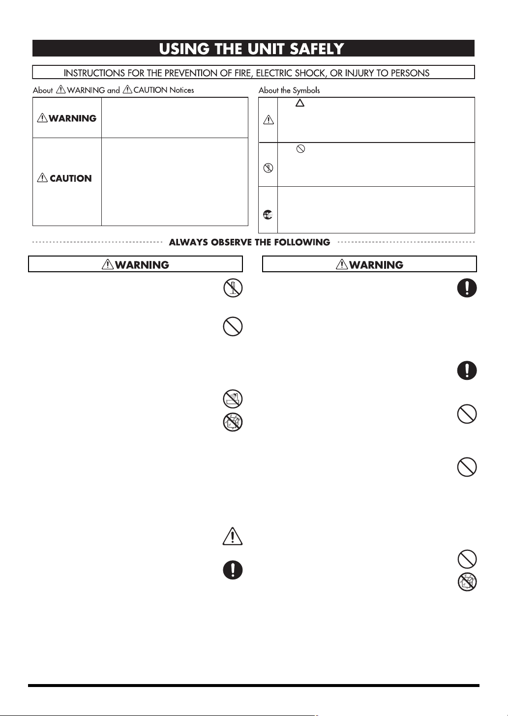
USING THE UNIT SAFELY
Used for instructions intended to alert the
user to the risk of death or severe injury
should the unit be used improperly.
Used for instructions intended to alert the
user to the risk of injury or material
damage should the unit be used
improperly.
* Material damage refers to damage or
other adverse eects caused with
respect to the home and all its
furnishings, as well to domestic animals
or pets.
002c
• Do not open (or modify in any way) the unit or its AC
adaptor.
....................................................................................................................
003
• Do not attempt to repair the unit, or replace parts
within it (except when this manual provides specific
instructions directing you to do so). Refer all servicing
to your retailer, the nearest Roland Service Center, or
an authorized Roland distributor, as listed on the
“Information” page.
....................................................................................................................
004
• Never install the unit in any of the following locations.
• Subject to temperature extremes (e.g., direct
sunlight in an enclosed vehicle, near a heating
duct, on top of heat-generating equipment); or are
• Damp (e.g., baths, washrooms, on wet floors); or are
• Exposed to steam or smoke; or are
• Subject to salt exposure; or are
•Humid; or are
• Exposed to rain; or are
• Dusty or sandy; or are
• Subject to high levels of vibration and shakiness.
....................................................................................................................
005
• This unit should be used only with a stand that is
recommended by Roland.
....................................................................................................................
006
• When using the unit with a stand recommended by
Roland, the stand must be carefully placed so it is level
and sure to remain stable. If not using a stand, you still
need to make sure that any location you choose for
placing the unit provides a level surface that will
properly support the unit, and keep it from wobbling.
....................................................................................................................
The symbol alerts the user to important instructions or
warnings.The specic meaning of the symbol is
determined by the design contained within the triangle. In
the case of the symbol at left, it is used for general
cautions, warnings, or alerts to danger.
The symbol alerts the user to items that must never be
carried out (are forbidden). The specic thing that must not
be done is indicated by the design contained within the
circle. In the case of the symbol at left, it means that the
unit must never be disassembled.
The ● symbol alerts the user to things that must be
carried out. The specic thing that must be done is
indicated by the design contained within the circle. In the
case of the symbol at left, it means that the power-cord
plug must be unplugged from the outlet.
008c
• Be sure to use only the AC adaptor supplied with the
unit. Also, make sure the line voltage at the installation
matches the input voltage specified on the AC
adaptor’s body. Other AC adaptors may use a different
polarity, or be designed for a different voltage, so their
use could result in damage, malfunction, or electric
shock.
....................................................................................................................
008e
• Use only the attached power-supply cord. Also, the
supplied power cord must not be used with any other
device.
....................................................................................................................
009
• Do not excessively twist or bend the power cord, nor
place heavy objects on it. Doing so can damage the
cord, producing severed elements and short circuits.
Damaged cords are fire and shock hazards!
....................................................................................................................
010
• This unit, either alone or in combination with an
amplifier and headphones or speakers, may be
capable of producing sound levels that could cause
permanent hearing loss. Do not operate for a long
period of time at a high volume level, or at a level that
is uncomfortable. If you experience any hearing loss or
ringing in the ears, you should immediately stop using
the unit, and consult an audiologist.
....................................................................................................................
011
• Do not allow any objects (e.g., flammable material,
coins, pins); or liquids of any kind (water, soft drinks,
etc.) to penetrate the unit.
....................................................................................................................
2
Page 5
012b
• Immediately turn the power off, remove the AC
adaptor from the outlet, and request servicing by your
retailer, the nearest Roland Service Center, or an
authorized Roland distributor, as listed on the “Information” page when:
• The AC adaptor, the power-supply cord, or the plug
has been damaged; or
• If smoke or unusual odor occurs
• Objects have fallen into, or liquid has been spilled
onto the unit; or
• The unit has been exposed to rain (or otherwise has
become wet); or
• The unit does not appear to operate normally or
exhibits a marked change in performance.
....................................................................................................................
013
• In households with small children, an adult should
provide supervision until the child is capable of
following all the rules essential for the safe operation
of the unit.
....................................................................................................................
014
• Protect the unit from strong impact.
(Do not drop it!)
....................................................................................................................
015
• Do not force the unit’s power-supply cord to share an
outlet with an unreasonable number of other devices.
Be especially careful when using extension cords—the
total power used by all devices you have connected to
the extension cord’s outlet must never exceed the
power rating (watts/amperes) for the extension cord.
Excessive loads can cause the insulation on the cord to
heat up and eventually melt through.
....................................................................................................................
016
• Before using the unit in a foreign country, consult with
your retailer, the nearest Roland Service Center, or an
authorized Roland distributor, as listed on the “Information” page.
....................................................................................................................
101b
• The unit and the AC adaptor should be located so
their location or position does not interfere with their
proper ventilation.
....................................................................................................................
101c
• This (TD-4) for use only with Roland stand MDS series.
Use with other stands is capable of resulting in instability causing possible injury.
....................................................................................................................
101f
• Please be sure to read and adhere to the cautionary
notices contained in the instructions that came with
this product.
Please note that, depending on the manner in which
keyboard performances are carried out, you may
encounter situations where the keyboard falls off the
stand or the stand topples over, even though you
have followed all of the instructions and advice
contained within the product’s manual. For this
reason, you should always perform a safety check
each time you use the stand.
....................................................................................................................
102c
• Always grasp only the plug on the AC adaptor cord
when plugging into, or unplugging from, an outlet or
this unit.
....................................................................................................................
103b
• At regular intervals, you should unplug the AC adaptor
and clean it by using a dry cloth to wipe all dust and
other accumulations away from its prongs. Also,
disconnect the power plug from the power outlet
whenever the unit is to remain unused for an
extended period of time. Any accumulation of dust
between the power plug and the power outlet can
result in poor insulation and lead to fire.
....................................................................................................................
104
• Try to prevent cords and cables from becoming
entangled. Also, all cords and cables should be placed
so they are out of the reach of children.
....................................................................................................................
106
• Never climb on top of, nor place heavy objects on the
unit.
....................................................................................................................
107c
• Never handle the AC adaptor or its plugs with wet
hands when plugging into, or unplugging from, an
outlet or this unit.
....................................................................................................................
108b
• Before moving the unit, disconnect the AC adaptor
and all cords coming from external devices.
....................................................................................................................
109b
• Before cleaning the unit, turn off the power and
unplug the AC adaptor from the outlet.
....................................................................................................................
110b
• Whenever you suspect the possibility of lightning in
your area, disconnect the AC adaptor from the outlet.
....................................................................................................................
118c
• Keep any caps and wing bolts you may remove in a
safe plac e out of child ren’s reach, so there is no chance
of them being swallowed accidentally.
....................................................................................................................
Deutsch Français Italiano Español Português NederlandsEnglish
3
Page 6

IMPORTANT NOTES
Power Supply
301
• Do not connect this unit to same electrical outlet that is being
used by an electrical appliance that is controlled by an inverter
(such as a refrigerator, washing machine, microwave oven, or
air conditioner), or that contains a motor. Depending on the
way in which the electrical appliance is used, power supply
noise may cause this unit to malfunction or may produce
audible noise. If it is not practical to use a separate electrical
outlet, connect a power supply noise filter between this unit
and the electrical outlet.
302
• The AC adaptor will begin to generate heat after long hours of
consecutive use. This is normal, and is not a cause for concern.
307
• Before connecting this unit to other devices, turn off the power
to all units. This will help prevent malfunctions and/or damage
to speakers or other devices.
Placement
351
• Using the unit near power amplifiers (or other equipment
containing large power transformers) may induce hum. To
alleviate the problem, change the orientation of this unit; or
move it farther away from the source of interference.
352a
• This device may interfere with radio and television reception.
Do not use this device in the vicinity of such receivers.
352b
• Noise may be produced if wireless communications devices,
such as cell phones, are operated in the vicinity of this unit.
Such noise could occur when receiving or initiating a call, or
while conversing. Should you experience such problems, you
should relocate such wireless devices so they are at a greater
distance from this unit, or switch them off.
354a
• Do not expose the unit to direct sunlight, place it near devices
that radiate heat, leave it inside an enclosed vehicle, or
otherwise subject it to temperature extremes. Excessive heat
can deform or discolor the unit.
355b
• When moved from one location to another where the temperature and/or humidity is very different, water droplets (condensation) may form inside the unit. Damage or malfunction may
result if you attempt to use the unit in this condition. Therefore,
before using the unit, you must allow it to stand for several
hours, until the condensation has completely evaporated.
Maintenance
401a
• For everyday cleaning wipe the unit with a soft, dry cloth or
one that has been slightly dampened with water. To remove
stubborn dirt, use a cloth impregnated with a mild, nonabrasive detergent. Afterwards, be sure to wipe the unit
thoroughly with a soft, dry cloth.
402
• Never use benzine, thinners, alcohol or solvents of any kind, to
avoid the possibility of discoloration and/or deformation.
Repairs and Data
452
• Please be aware that all data contained in the unit’s memory
may be lost when the unit is sent for repairs. Important data
should always be written down on paper (when possible).
During repairs, due care is taken to avoid the loss of data.
However, in certain cases (such as when circuitry related to
memory itself is out of order), we regret that it may not be
possible to restore the data, and Roland assumes no liability
concerning such loss of data.
Additional Precautions
553
• Use a reasonable amount of care when using the unit’s
buttons, sliders, or other controls; and when using its jacks and
connectors. Rough handling can lead to malfunctions.
554
• Never strike or apply strong pressure to the display.
556
• When connecting / disconnecting all cables, grasp the
connector itself—never pull on the cable. This way you will
avoid causing shorts, or damage to the cable’s internal
elements.
558a
• To avoid disturbing your neighbors, try to keep the unit’s
volume at reasonable levels. You may prefer to use
headphones, so you do not need to be concerned about those
around you (especially when it is late at night).
558c
• Since sound vibrations can be transmitted through floors and
walls to a greater degree than expected, take care not to allow
such sound to become a nuisance to neighbors, especially at
night and when using headphones. Although the drum pads
and pedals are designed so there is a minimal amount of extraneous sound produced when they’re struck, rubber heads tend
to produce louder sounds compared to mesh heads. You can
effectively reduce much of the unwanted sound from the pads
by switching to mesh heads.
559a
• When you need to transport the unit, package it in the box
(including padding) that it came in, if possible. Otherwise, you
will need to use equivalent packaging materials.
562
• Some connection cables contain resistors. Do not use cables
that incorporate resistors for connecting to this unit. The use of
such cables can cause the sound level to be extremely low, or
impossible to hear. For information on cable specifications,
contact the manufacturer of the cable.
985
• The explanations in this manual include illustrations that
depict what should typically be shown by the display. Note,
however, that your unit may incorporate a newer, enhanced
version of the system (e.g., includes newer sounds), so what
you actually see in the display may not always match what
appears in the manual.
• If there is a danger that you might accidentally strike the unit
during performance, adjust the locations at which Tom 1 (T1)
and Tom 2 (T2) are attached to the stand, to reduce the gap
between the pads.
4
Page 7

Contents
USING THE UNIT SAFELY.......................... 2
IMPORTANT NOTES.................................. 4
Panel Descriptions ................................... 6
Front Panel ...........................................................................6
Side Panel .............................................................................7
Rear Panel .............................................................................7
Bottom Panel ......................................................................7
Getting Ready to Play .............................. 8
Mounting the TD-4 on the Stand .................................8
Connecting Your Audio Equipment............................9
Turning the Power On/Off...........................................10
Saving Your Settings........................................................................10
Tensioning the Head of a Mesh Pad (PDX-8) ........11
Playing..................................................... 12
Hearing What the Kits Sound Like ............................ 12
Selecting a Drum Kit ...................................................... 12
About the “DRUM KIT” screen.......................................................12
Performance Techniques .............................................13
Pads (e.g., PDX-8, PD-8)................................................................... 13
Cymbals (e.g., CY-8, CY-12R/C)..................................................... 13
Hi-Hat (CY-5)........................................................................................ 14
Hi-Hat Control Pedal FD-8.............................................................. 14
Quickly Tuning or Muffling.......................................... 15
TUNING..................................................................................................15
MUFFLING ............................................................................................15
Playing Along with a Portable Audio Player ......... 16
Practicing ................................................ 17
Playing with the Metronome......................................17
Quick Recording and Playback (QUICK REC)......... 17
Recording............................................................................................. 17
Playback................................................................................................ 18
Using Time Check to Check Your Recorded Performance .18
Practicing in Coach Mode ............................................ 19
Selecting a Practice Menu.............................................................. 19
<1> WARM UPS..................................................................................20
<2>
Correctly Playing in Time with the Beat (TIME CHECK)........ 22
<3>
Continuing to play at a steady tempo (TEMPO CHECK) ......23
<4>
Developing Internal Timing Sense (QUIET COUNT)..............24
<5>
Gradually raising and lowering the tempo (AUTO UP/DOWN)
..... 26
Creating a Drum Kit ................................27
Selecting the Parameters ............................................. 27
Editing Instrument Parameters (INSTRUMENT) ...28
Adjusting the volume of the pads or drum kit
(MIXER)................................................................................ 29
Using the Onboard Effects (AMBIENCE) ................. 30
Naming a Drum Kit (KIT NAME).................................. 30
Copying a Drum Kit (COPY) ......................................... 31
Exchanging Drum Kits (EXCHANGE) ........................ 32
Restoring a Drum Kit (RESTORE)................................ 33
System Settings.......................................34
Specifying How the Metronome will Sound
(METRONOME) ................................................................. 34
Editing the pad settings (PAD SETTINGS) .............. 35
Specifying the Type of Pad ............................................................ 35
Setting the Pad Sensitivity ............................................................. 35
Specifying How the CR2 Trigger Cable will be Used ............ 36
Other Settings (OPTIONS) ............................................ 36
Adjusting the Display Contrast (LCD Contrast) ...................... 37
Adjusting the Brightness of the Backlight (LCD Bright) ...... 37
Adjusting the Button Operating Sound (Keypad Sound)... 37
Allowing the Head and Rim Settings to be Edited
Separately (Head/Rim Link) ........................................................... 37
Restoring the Factory Settings (Factory Reset).......................37
Expanding your drum set.......................38
Adding a CRASH 2 cymbal........................................... 38
Using a CY-12R/C or CY-15R instead of the
CY-8 cymbal ...................................................................... 38
Using the VH-11 V Hi-hat.............................................. 39
Connecting the VH-11 and Making Settings on the TD-4
.....39
Other Settings .........................................41
MIDI Settings .................................................................... 41
MIDI-related Settings.......................................................................41
Detailed Settings for Trigger Parameters............... 42
Protecting Modified Kits and Settings
(Edit Lock) .......................................................................... 45
Troubleshooting .....................................46
Error Messages ........................................48
Drum Kit/Instrument List .......................49
MIDI Implementation Chart ...................51
Specifications ..........................................52
Index ........................................................53
Deutsch Français Italiano Español Português NederlandsEnglish
5
Page 8
Panel Descriptions
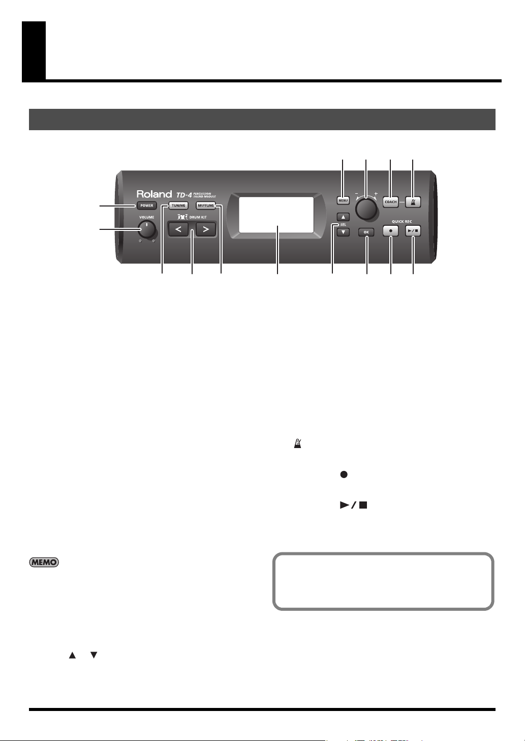
Front Panel
fig.FrontP.eps
1
2
354 6 8 101314
7 9 11 12
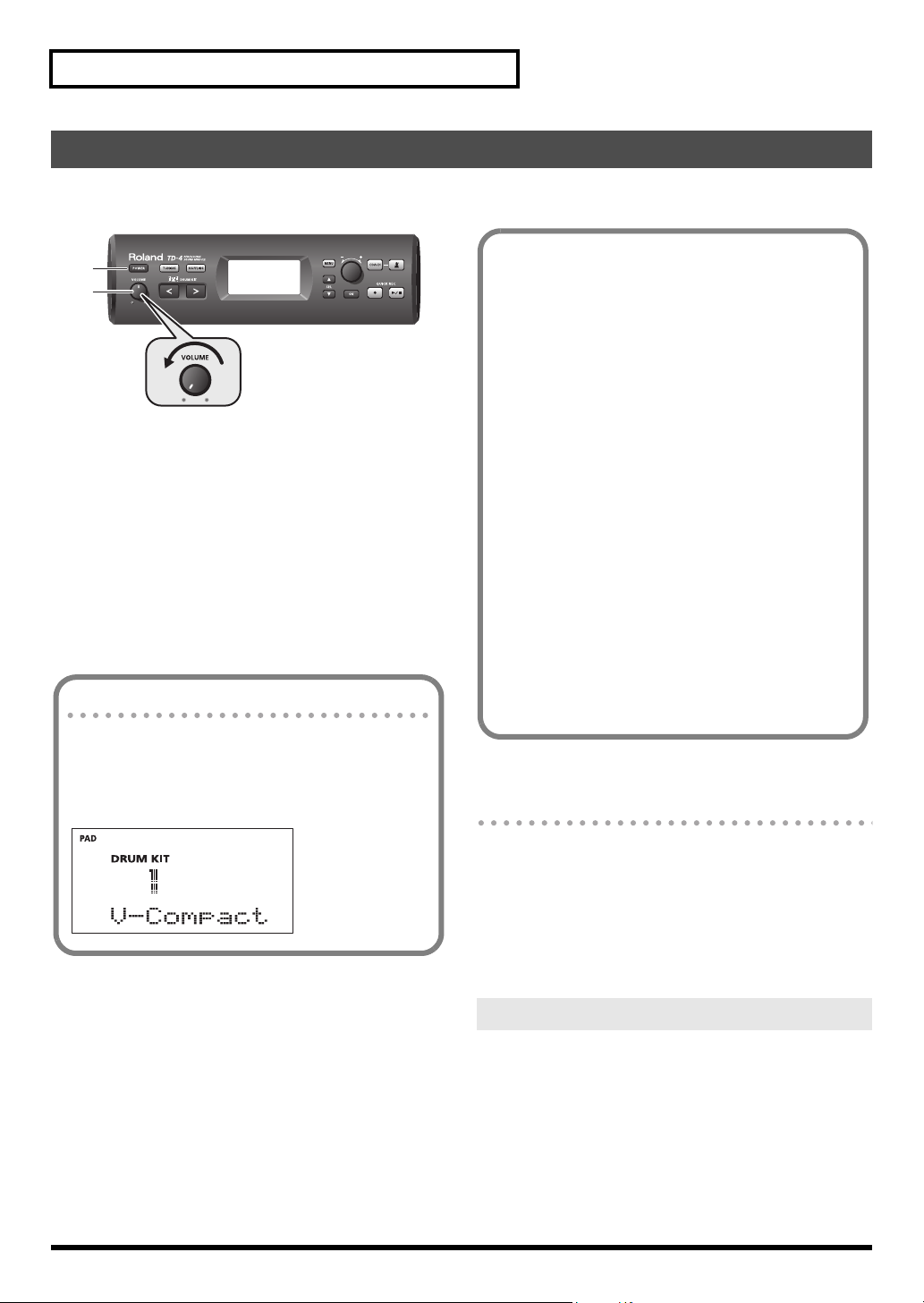
1. [POWER] button
Turns the power on/off (p. 10).
2. [VOLUME] knob
Adjusts the volume from the OUTPUT and PHONES jacks (p.
10).
3. [TUNING] button
Use this when you want to tune each instrumental sound (p.
15).
4. [MUFFLING] button
Use this when you want to muffle (mute) each instrumental
sound (p. 15).
5. DRUM KIT [<] [>] buttons
Use these to switch drum kits (p. 12). You’ll also use these
buttons to return to the drum kit screen from other screens
(except during recording/playback).
6. Display
During performance, this shows the drum kit name and other
information. During editing, this shows the contents of the
settings.
The backlight will automatically dim when no panel
operations have been performed for a certain period of time.
7. [MENU] button
Use this when you want to make various settings for the TD4, such as editing the settings of a drum kit or adjusting the
pads.
9. [-/+] dial
Use this dial to edit a value.
Use this to adjust a value. Turning the dial toward “+” will
increase the value, and turning it toward “-” will decrease the
value.
10. [OK] button
Use this to confirm a menu item to use with the Coach
function, or to confirm a value you’ve edited.
11. [COACH] button
Press this when you want to use the Coach function (p. 19).
12. [ ] (Metronome) button
This turns the metronome on (sounding) or off (silent) (p. 17).
13. QUICK REC [ ] (Rec) button
Use this to record your playing (p. 17).
14. QUICK REC [ ] (Play/Stop) button
Play back what you recorded (p. 18).
With some buttons, a sound is produced when you press
them.
If you want, you can turn off this sound (p. 37).
8. SEL [ ] [ ] button
Use this to select a menu item when using the Coach
function, or to select parameters when making various
settings for the TD-4.
6
Page 9
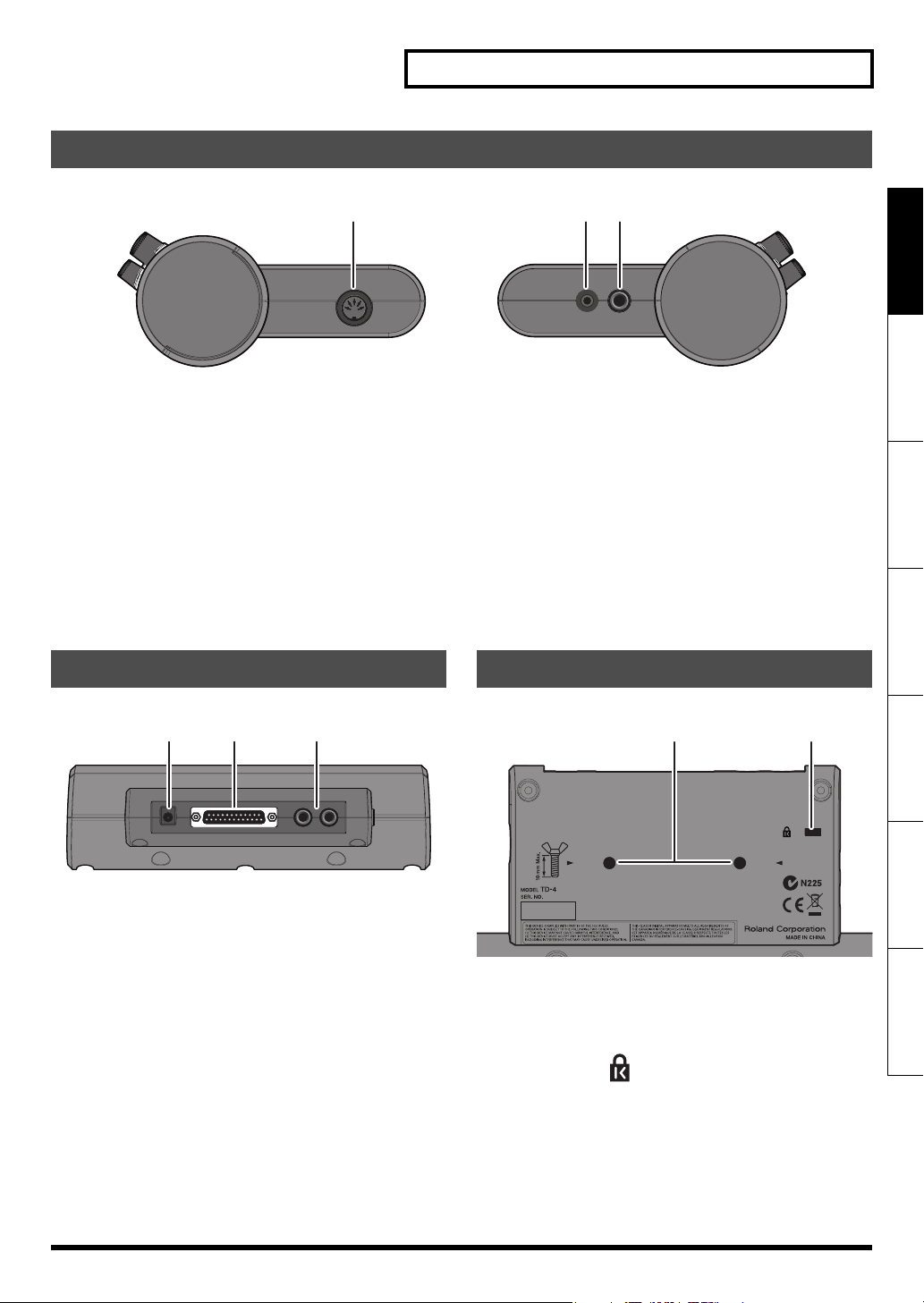
Side Panel
fig.SideP.eps
Panel Descriptions
15 16 17
Deutsch Français Italiano Español Português NederlandsEnglish
15. MIDI OUT connector
Use this when you want to use the pads to play external MIDI
sound sources or for recording with sequencers (p. 41).
Rear Panel
fig.RearP.epss
18 19 20
18. DC IN jack
Connect the included AC adaptor here (p. 9).
19. TRIGGER INPUT connector
Connecting the special cable connects the pads and pedals
to the TD-4 (p. 8).
20. OUTPUT jacks (L/MONO, R)
All sounds of the TD-4 are output here. Use for connecting to
an amp or other external audio equipment.
If you’re working in mono, only use the L/MONO jack.
16. MIX IN jack
For connecting an external audio source such as MP3 or CD
players (p. 16). All sound input here is also sent from the
OUTPUT and PHONES jacks.
* To adjust the volume, use the controls of the external device
connected to MIX IN.
17. PHONES jack
For connecting stereo headphones (p. 9).
Using the headphone jack will not mute the main OUTPUT
jacks.
Bottom Panel
fig.BottomP.eps
2221
21. Sound module mounting plate attachment holes
Attach the included sound module mounting plate here so
that you can attach the TD-4 to your drum stand.
22. Security Slot ( )
http://www.kensington.com/
7
Page 10
Getting Ready to Play
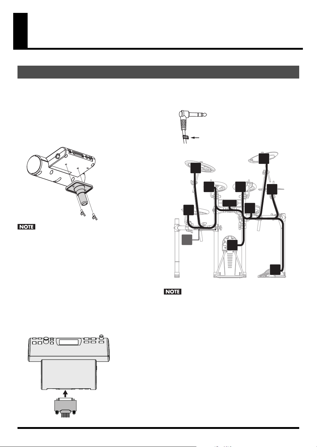
Mounting the TD-4 on the Stand
1. Attach the included sound module mounting plate
to the TD-4.
Use the included wing bolts to attach the plate as shown in
the illustration.
* Use only the included wing bolts. Using any other nuts may
cause malfunction.
* You must use the TD-4 with the sound module mounting
plate installed.
fig.H-mounting.eps
• When turning the unit upside-down, get a bunch of
newspapers or magazines, and place them under the four
corners or at both ends to prevent damage to the buttons
and controls. Also, you should try to orient the unit so no
buttons or controls get damaged.
• When turning the unit upside-down, handle with care to
avoid dropping it, or allowing it to fall or tip over.
2. Attach the TD-4 (with the sound module mounting
plate installed) to your drum stand (such as the
MDS-4; available separately).
3. Connect the included cable to the TD-4’s TRIGGER
INPUT connector, and connect your pads and
pedals.
fig.Connecter-joint.eps
Labels indicating the pad to be connected are attached to
the cable.
Connect the pads and pedals as shown in the illustration.
fig.Trig-Plug.eps
fig.Connect-cable.eps
CR1
RD
T3
T1T2
TD-4
SNR
HH
CR2
KIK
HHC
• If you don’t connect a pad to each of the cables, make the
following settings for unconnected pads in order to prevent
malfunction.
• Turn the Pad Type setting OFF (p. 35).
• If you’re not using the CR2, leave the CR2 cable cap attached,
and fasten the cable to the stand so that it does not interfere
with your playing.
• The included connection cables are the optimal length for
when they're attached to the MDS-4. If you’re using a
different stand, you'll need to provide extension cables.
8
Page 11
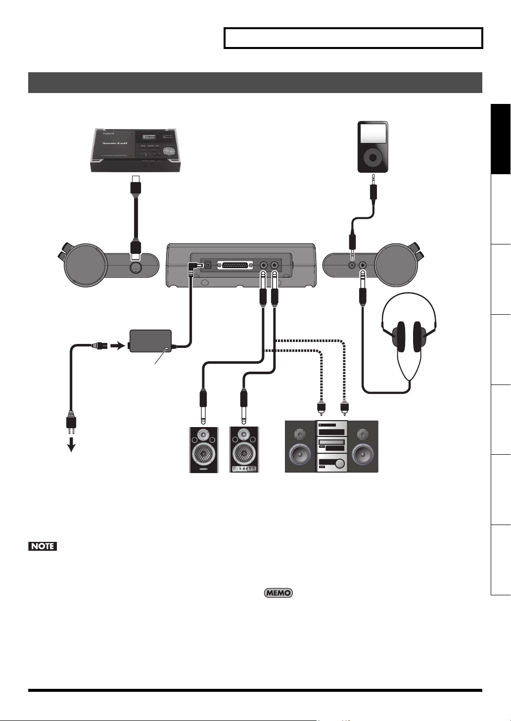
Connecting Your Audio Equipment
fig.Connection.eps
MIDI Sound Module
MIDI IN
AC Adaptor
Getting Ready to Play
Portable Audio Player
Deutsch Français Italiano Español Português NederlandsEnglish
Stereo
miniature plug
Stereo
1/4” phone plug
Power Cord
To AC Outlet
Indicator
Powered Amp, etc
1. Power-off all equipment before making
connections.
To prevent malfunction and/or damage to speakers or other
devices, always turn down the volume, and turn off the
power on all devices before making connections.
2. Connect the OUTPUT jacks (L/MONO, R) to your
audio system or amp.
*If you’re using headphones, connect them to the PHONES
jack.
Stereo
Headphones
Audio Set, etc
3. Connect the included AC adaptor to the DC IN jack.
Place the AC adaptor so the side with the indicator (see
illustration) faces upwards and the side with written
information faces downwards.
* The indicator will light when you plug the AC adaptor into an
AC outlet.
Using the MIX IN jack allows playing along with music from a
portable audio player or other external sources (p. 16).
9
Page 12
Getting Ready to Play
Turning the Power On/Off
* Once connections have been made (p. 9), turn on the power to the connected equipment in the order specified. Doing it in the wrong
order raises the risk of damage/malfunction to that equipment.
fig.P-PowerOn.eps
If you don’t hear any sound
3
1
Check the following points.
Pad and Pedal Connections
• Is the cable correctly connected to the TRIGGER INPUT
connector?
• Are the cables correctly connected to each pad or
pedal?
1. Turn the [VOLUME] knob all the way to the left.
2. Minimize the volume of the connected amp or
audio system.
3. Press the [POWER] button.
* Even with the volume all the way down, you may still hear
some sound when the power is switched on, but this is
normal, and does not indicate a malfunction.
* The TD-4 is equipped with a protection circuit and requires a
brief interval a few seconds) after powering before it will
operate normally.
Caution when Turning On the Power
After you turn on the power, do NOT touch any pads or
pedals until the drum kit name (the illustration below) has
appeared in the display. Doing so can cause various
problems.
ig.d-OpenKitNo1.eps
When Using an Amp or Audio System
• Are the TD-4’s OUTPUT jacks connected correctly to the
input jacks of your amp/audio system?
• Are the input selections and volume settings correct on
that amp/audio system?
• Possible problem with the connection cables
themselves?
• Isn’t the [VOLUME] knob turned all the way to the left?
• Have the input select settings of your audio system or
amp been made correctly?
• Is the amp or audio system volume setting correct?
When using headphones
• Are your headphones plugged into PHONES jack?
• Isn’t the [VOLUME] knob turned all the way to the left?
Turning the Power Off
1. Turn the volume down on the TD-4 and any
connected equipment.
2. Power-off the connected equipment.
3. Hold down the [POWER] button until the display
indicates “See you!”
4. Power-on the connected amp or audio system.
5. While hitting a pad, gradually turn the [VOLUME]
knob toward the right to adjust the volume.
Adjust the volume of the connected amp/ audio system to
the desired level.
10
Saving Your Settings
The TD-4 does not have a specific “operation” for saving your
settings. Any changes you’ve made will be saved when you turn
off the power.
* You must turn off the power by pressing the [POWER] button.
Page 13
Getting Ready to Play
Tensioning the Head of a Mesh Pad (PDX-8)
BEFORE using the PDX-8 mesh pads you must adjust the tension.
You can tension mesh heads the same way you do with acoustic drums.
* Use a drum key to make adjustments.
Adjusting the tension of the PDX-8 head is only for playing response and will not affect the pitch as on an acoustic drum.
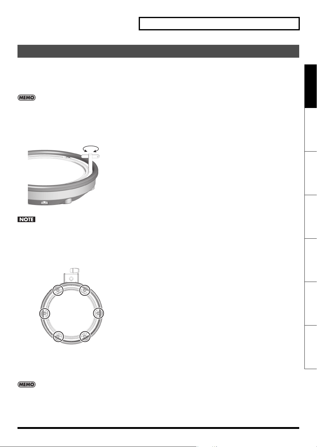
1. Use the included drum key to tighten the tuning
bolts.
Strike the head to check the feel and response.
fig.PDX8-Adj.eps
Loosen Tighten
fig.PDX8-Bolt.eps
Tighten the tuning bolts in the numerical order shown in the
following illustration. If you firmly tighten a tuning bolt at
one location all at once, it will be impossible to stretch the
head evenly, and this may cause triggering response
problems.
6
1
Deutsch Français Italiano Español Português NederlandsEnglish
4
2
3
5
2. Tension the head evenly as you test the playing
feel, just as you would with an acoustic drum.
Head tension may slacken with the passage of time. Readjust
the tension as needed.
11
Page 14
Playing
Hearing What the Kits Sound Like
After turning the power on, you can play the demo patterns.
Here’s how you can listen to the sounds by switching drum kits
while playing the demo patterns.
fig.P-Demo.eps
2 1, 3
* All rights reserved. Unauthorized use of this material for
purposes other than private, personal enjoyment is a
violation of applicable laws.
* No data for the demo patterns that is played will be output
from MIDI OUT.
Selecting a Drum Kit
A drum kit is a combination of the sounds & settings for each pad
and pedal, as well as ambience.
fig.P-DrumKit.eps
1. Press the [ ] (Play/Stop) button.
The demo patterns will play.
2. Press the DRUM KIT [<] [>] buttons to select drum
kit.
3. To stop demo pattern playback, press the
[ ] button once again.
When you press the [ ] (Rec) button to start recording
your performance (p. 17), the demo patterns will temporarily
be erased. The next time you turn on the power, you will
again be able to play the demo patterns.
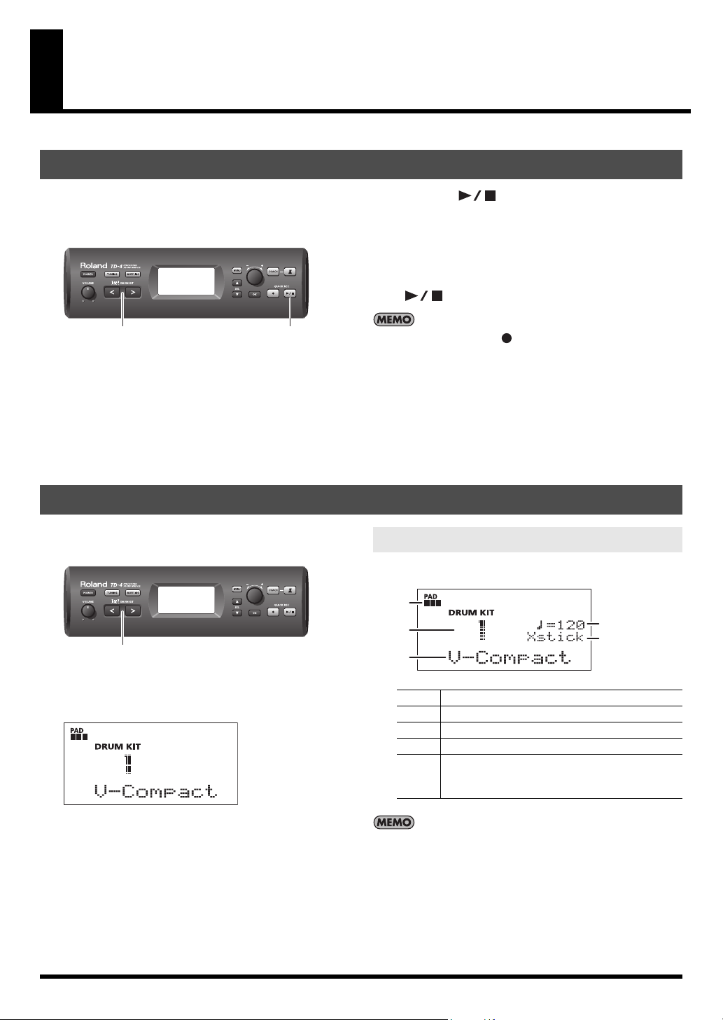
About the “DRUM KIT” screen
This is the TD-4’s basic screen.
fig.d-KitNo1.eps
1
1. Press the DRUM KIT [<] [>] buttons to select drum
kit.
fig.d-KitScreen.eps
12
D
A
C
E
B
A Drum kit number
B Drum kit name
C This shows the metronome tempo (p. 17).
D Strength of the pad strike displayed in 6 levels.
This is shown if the cross-stick technique can be
E
Regardless of the screen that is displayed, pressing the DRUM
KIT [<] [>] buttons will access the “DRUM KIT” screen (except
during recording/playback).
used with the snare (p. 29).
(When Xstick Volume is anything other than OFF)
Page 15
Performance Techniques
Playing
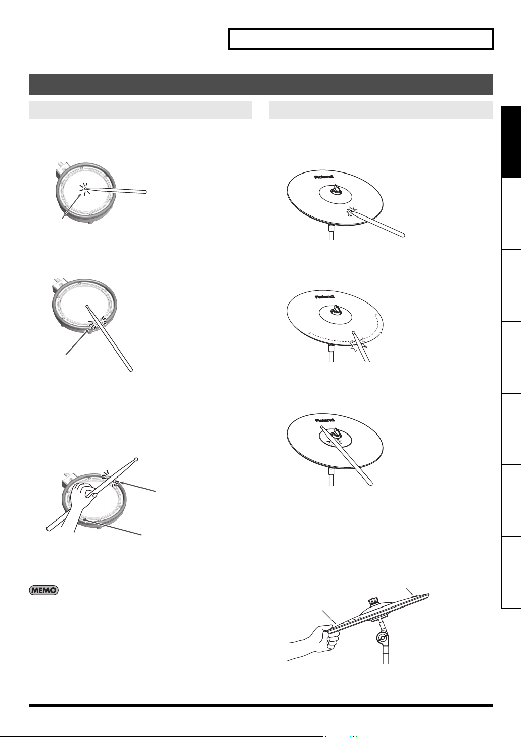
Pads (e.g., PDX-8, PD-8)
Head Shot
Hit only the head of the pad.
fig.Play-Head.eps
Head
Open Rim Shot
Strike the rim of the pad.
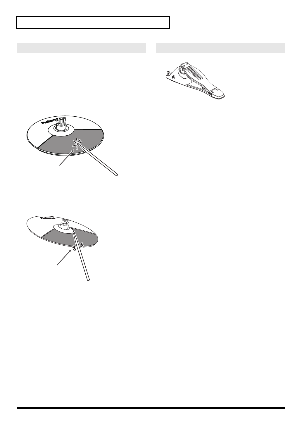
fig.Play-Rim.eps
Rim
Cross Stick
Only strike the rim of the pad.
Velocity switching “snare rim” sound, played softly produces a
cross stick sound, and when played harder, produces a open rim
shot sound (p. 29).
fig.Play-Cross.eps
Cymbals (e.g., CY-8, CY-12R/C)
Bow Shot
The most common method, playing the middle area of the
cymbal.
fig.Play-CYBow.eps
Deutsch Français Italiano Español Português NederlandsEnglish
Edge Shot
When striking the edge with the shoulder of the stick (as shown in
the figure).
fig.Play-CYEdge.eps
Edge Sensor
Bell Shot (CY-12R/C, CY-15R)
This playing method involves striking the bell of the cymbal.
* Set the Crash 2 Usage setting (p. 36) to “RIDE BELL.”
fig.Play-CYBell.eps
Rim
Rim
* To play the cross stick, be sure that you only strike the rim of
the pad. Place your hand on the head gently, otherwise this
may prevent the cross stick function from working properly.
When playing cross stick, set “Xstick Volume” (p. 29) to
anything other than “OFF.”
* Strike the bell somewhat strongly with the shoulder of the stick.
Choking a Cymbal
Choking (pinching) the cymbal’s edge with the hand immediately
after hitting the cymbal will mute or choke the sound, just like
with a real cymbal. The Choke function only works when you grasp
in the area (where the edge sensor is) as shown in the figure. If you
do otherwise, it will not work.
fig.Play-Choke.eps
Roland Logo
Edge Sensor
13
Page 16
Playing
Hi-Hat (CY-5)
Open/Closed
The hi-hat sound will change smoothly between open and closed
depending on pressure applied to the hi-hat control pedal.
Foot closed and foot splash sounds are possible.
Bow Shot
Playing the middle area of the hi-hat pad.
fig.Play-VHBow.eps
Bow
Edge Shot
Playing the edge of the hi-hat pad with the shoulder of the stick
(as shown in the figure).
fig.Play-VHEdge.eps
Hi-Hat Control Pedal FD-8
fig.FD-8.eps
Open Hi-Hat
Strike the hi-hat without pressing the pedal.
Half Open Hi-Hat
Strike the hi-hat with the pedal pressed half-way.
Closed Hi-Hat
Strike the hi-hat with the pedal pressed.
Foot Closed
Completely press down the pedal.
Foot Splash
Quickly hitting the hi-hat pedal (with heel or toes) and instantly
releasing it.
Edge
* Connect the FD-8 to the TD-4 before turning on the power.
14
Page 17
Playing
Quickly Tuning or Muffling
You can use dedicated buttons to quickly tune or muffle the sound. When you press the button, the sound you selected will be heard.
You cannot make tuning or muffling settings for pads to which an instrument (p. 28) in the cymbal-type instrument group (HIHAT,
CRASH, RIDE) is assigned. For such pads, the display will indicate “- - -.”
TUNING
fig.P-Tuning.eps
3
1, 5
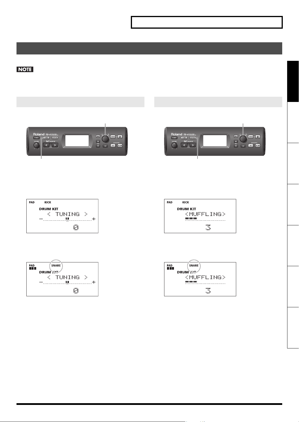
1. Press the [TUNING] button so it’s lit.
The TUNING screen appears.
The selected pad will sound at this time.
fig.d-Tuning-1.eps
2. Strike the pad that you want to tune.
The pad you struck will blink in the screen.
fig.d-Tuning-2.eps
MUFFLING
fig.P-Muffling.eps
3
1, 5
1. Press the [MUFFLING] button so it’s lit.
The MUFFLING screen appears.
The selected pad will sound at this time.
fig.d-Muffling-1.eps
2. Strike the pad that you want to muffle.
The pad you struck will blink in the screen.
fig.d-Muffling-2.eps
Deutsch Français Italiano Español Português NederlandsEnglish
3. While striking the pad to hear the sound, turn the [/+] dial to adjust the tuning.
Value: -600–0–+600
A negative (-) value will lower the pitch, and a positive (+)
value will raise the pitch.
4. Repeat steps 2–3 to adjust the tuning of each pad.
5. When you’ve finished tuning, press the [TUNING]
button to turn it off.
3. While striking the pad to hear the sound, turn the
[-/+] dial to adjust the muffling.
Value: 0–10
Raising this value reduces the resonance and decay (length)
of the sound.
4. Repeat steps 2–3 to adjust the muffling of each
pad.
5. When you’ve finished adjusting the muffling, press
the [MUFFLING] button to turn it off.
15
Page 18
Playing
If Head/Rim Link (p. 37) is “ON,” both the HEAD and the RIM settings will be edited simultaneously.
In some cases, you may see an “*” in the right side of the screen; this indicates that the tuning/muffling values specified for the
HEAD and the RIM are different.
Playing Along with a Portable Audio Player
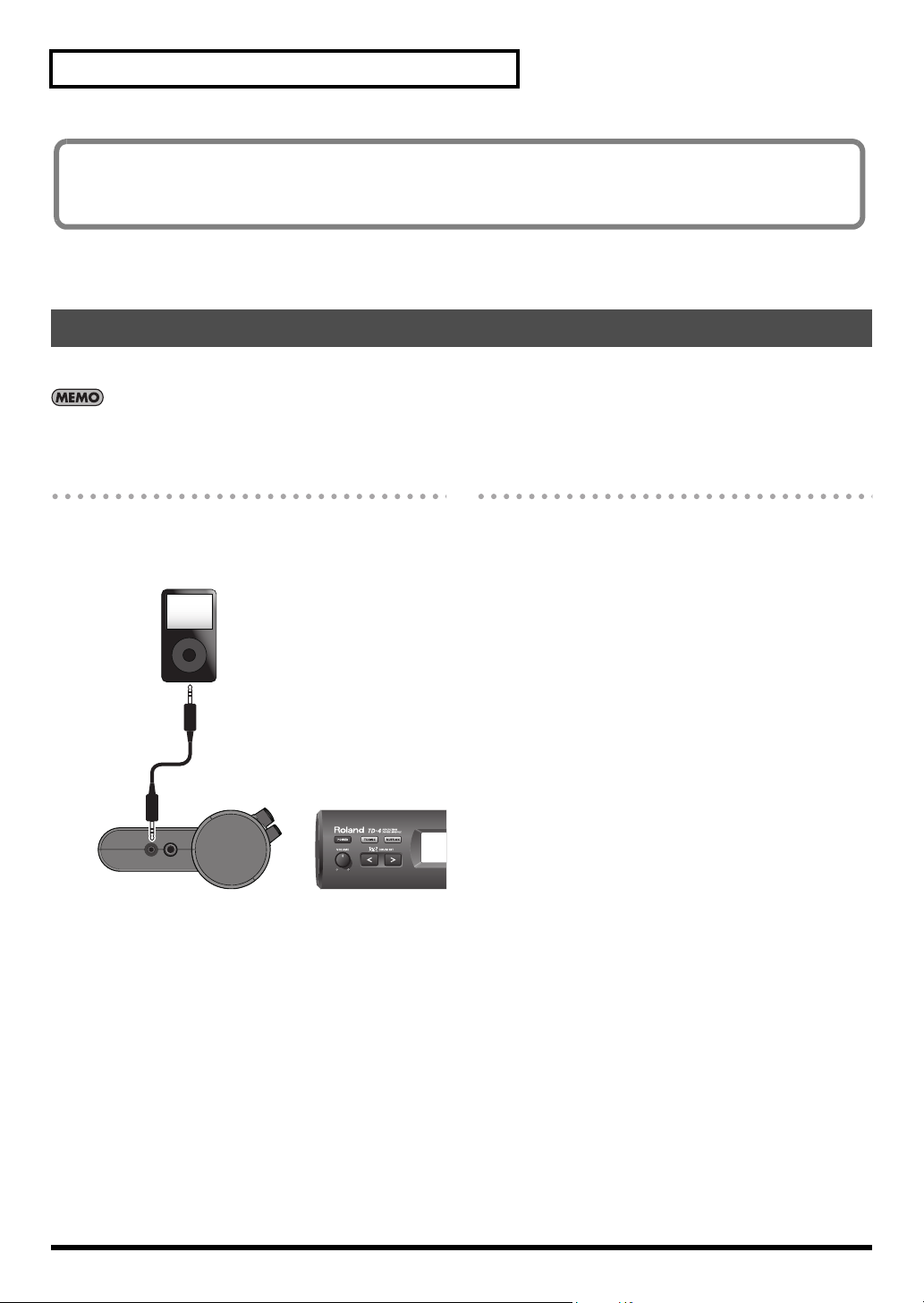
By connecting a portable audio/CD player to the MIX IN jack you can play the TD-4 with your favorite songs.
You can connect other audio devices as well.
Connections
Lower the volume of the TD-4 and your audio player before
making connections.
fig.Connect-iPod.eps
Portable Audio Player
Stereo
miniature plug
* If a connection cable has built-in resistors, the volume level of
the source connected to the TD-4 (MIX IN) may be too low. If
this occurs, use connection cables that do not contain
resistors.
Playback
1. Start the music on your portable audio player.
For details on how to use your audio player, refer to its
owner’s manual.
2. Then adjust the volume of your portable audio
player.
Sounds received at the MIX IN jack are output from the
OUTPUT and PHONES jacks.
* Adjust the volume on the audio player to get the right
balance between it and the TD-4.
3. Adjust the volume of the TD-4.
16
Page 19

Practicing
Playing with the Metronome
fig.P-Metronome.eps
1, 32
1. Press the [ ] button.
The metronome starts and the screen will indicate the tempo.
The button will blink in time with the metronome.
fig.d-Metro.eps
2. Turn the [-/+] dial to adjust the tempo.
Value: 40–260
3. To turn off the metronome, press the [ ] button
to turn it off.
Quick Recording and Playback (QUICK REC)
The TD-4 provides a Quick Rec function that lets you easily record
your own performance. This is a very useful practice tool,
recording and then checking your drumming.
Deutsch Français Italiano Español Português NederlandsEnglish
Whenever you turn on the power, the TD-4 is prepared for
the playback of its demo patterns.
After you’ve made a recording, if you turn off the power, the
data for the recording will be erased. Then, the next time the
power is switched on, the demo patterns will once again be
loaded in from internal memory.
A signal input via the MIX IN jack won’t be recorded.
Recording
fig.P-QuickRec.eps
Even without pressing the [ ] button, you can change the
tempo by turning the [-/+] dial in the Drum Kit screen.
You can change the way that the metronome sounds (p. 34).
1, 3
* First: Please select the drum kit that you want to use for
recording.
1. Press the [ ] (Rec) button.
The [ ] (Rec) button will blink, and the TD-4 will enter
recording-standby mode.
fig.d-Rec-1.eps
• To record along with the metronome, press the [ ] button
to turn the metronome on, and use the [-/+] dial to adjust the
tempo.
17
Page 20

Practicing
2. Hit any pad/pedal and recording begins.
The following screen appears.
fig.d-Rec-2.eps
3. To stop recording, press the [ ] (Rec) button and
the button goes dark.
* If you exceed the maximum recording time, recording stops
automatically.
fig.d-Rec-3.eps
Playback
fig.P-QuickPlay.eps
2. To stop playback, press the [ ] (Play/Stop)
button and the button goes dark.
When playback has finished, the [ ] (Play/Stop)
button automatically goes dark.
Using Time Check to Check Your Recorded Performance
You can use Coach mode’s “TIME CHECK” function to check
whether your recorded performance was played with accurate
timing.
You must play along with the metronome when recording.
1. Press the [ ] (Play/Stop) button so it’s lit; the
recorded performance will play.
2. Press the [COACH] button.
The following screen appears.
fig.d-RecCheck.eps
1, 2
1. Press the [ ] (Play/Stop) button so it’s lit.
The following screen appears, and playback begins.
fig.d-RecPlay-1.eps
* The recorded performance data is not transmitted from MIDI
OUT.
By holding down the [ ] (Play/Stop) button for about
one second, you can select loop playback; the recorded
performance will play repeatedly.
fig.d-LoopPlay.eps
Loop Playback
During playback, you can change the playback tempo by
turning the [-/+] dial. When you stop playback, the tempo will
revert to the setting at which it was recorded.
* Loop playback will automatically be selected and the
metronome will turn on.
3. To stop playback, press the [ ] (Play/Stop)
button and the button goes dark.
18
Page 21

Practicing
Practicing in Coach Mode
The TD-4’s Coach mode is a unique set of exercises specifically designed to help build speed, accuracy and stamina, as well as develop
better timing skills.
Throughout the Coach modes, you will discover that some of them have programmable parameters, allowing you to adapt the functions
to your specific needs.
Selecting a Practice Menu
fig.P-CoachMenu.ep s
1
23
1. Press the [COACH] button so it’s lit.
The Coach mode menu screen will appear.
fig.d-Tr-Menu-1.eps
Menu Explanation
Warm Ups
p. 20
When you want to get
w ar m e d u p b e fo r e yo u
begin practicing.
Time Check
p. 22
Strengthens your
ability to play accurate
rhythms.
Tempo Check
p. 23
Deutsch Français Italiano Español Português NederlandsEnglish
2. Use the SEL [ ] [ ] buttons to select the desired
practice menu item (shown at right).
3. When you’ve selected a practice menu item, press
the [OK] button.
You’ll proceed to the start screen of the selected practice
menu item.
Or you can just press the [ ] button to immediately start
practicing without calling up the start screen.
In the start screen of the Practice menu, you can press the
[MENU] button and make settings for each menu item.
Strengthens your
ability to play at a
consistent speed.
Quiet Count
p. 24
Strengthens your
ability to maintain the
tempo internally.
Auto Up/Down
p. 26
Strengthens your
endurance.
19
Page 22

Practicing
<1> WARM UPS
In this mode you’ll successively practice steps 1–3, be graded on your performance at each step, and then receive a final evaluation.
You can choose one of three courses, ranging from easy to difficult. You can also adjust the tempo according to your level of skill.
Start practicing
fig.WarmUp-1.eps
In the WARM UPS start screen, press the [ ]
button to start practicing.
After you’ve started WARM UPS, you can press the [ ]
button to pause the WARM UPS.
fig.WarmUp-6.eps
To resume practicing, press the [ ] button once again.
If you’re finished with WARM UPS, press the [OK] button.
Here you can press the SEL [ ] button to move to the
previous step, or press the SEL [ ] button to move to the
next step.
You can turn the [-/+] dial to adjust the tempo even while
practicing.
Step 2: AutoUpDown
The tempo will gradually be raised and lowered.
The tempo will increase by 1BPM (beat-per-minute) for each beat
until the metronome reaches the upper limit; then the tempo will
continue slowing down by 1BPM until it reaches the initial tempo.
* AutoUpDown will be executed if Duration (p. 21) is 10 MINS
or 15 MINS.
fig.d-WarmUp-3.eps
Tempo lower limit Tempo upper limit
* The current tempo value will be the lower tempo limit.
While practicing, you can press the SEL [ ] button to
specify the current tempo as the upper limit; if you press the
SEL [ ] button, the upper tempo limit will return to 260.
Step 3: TimeCheck
At this step, the accuracy of your playing will be checked against
the metronome. You can see in the screen if you are ahead, behind
or on the beat.
fig.WarmUp-4.eps
Step 1: Change-up
In this step, the rhythm type will change every two measures.
Starting from half notes, the note values will gradually become
shorter, and will then return to half notes; this change in rhythms
will be repeated.
fig.WarmUp-2.eps
Remaining
time
Current
note value
20
Lagging Correct Rushing
Overall evaluation
This grades your performance at each step, and displays the
overall evaluation.
fig.WarmUp-5.eps
Evaluation (display)
EXCELLENT!, VERY GOOD!, GOOD, AVERAGE, START OVER
Page 23

Practicing
When you’ve finished practicing
Press the [OK] button to return to the Coach mode
menu screen.
Select a course and make settings
1. From the WARM UPS start screen, press the [MENU]
button so it’s lit.
fig.WarmUp-Op1.eps
2. Use the SEL [ ] [ ] buttons to select a
parameter.
3. Turn the [-/+] dial to edit the value.
4. Press the [MENU] button to return to the WARM
UPS start screen.
Duration (time selection):
fig.WarmUp-Op1.eps
Change-up:
Step 1: Selects the pattern by which the rhythm will vary during
Change-up.
fig.WarmUp-Op3.eps
Value Explanation
MaxTempo:
Step 2: Specifies the upper tempo limit during step 2:
AutoUpDown.
fig.WarmUp-Op4.eps
Deutsch Français Italiano Español Português NederlandsEnglish
Value Explanation
5 MINS
10 MINS
15 MINS
Time required: 5 minutes
Change-up: 2 minutes, TimeCheck: 3 minutes
Time required: 10 minutes
Change-up: 3 minutes, AutoUpDown: 3 minutes, TimeCheck: 4 minutes
Time required: 15 minutes
Change-up: 5 minutes, AutoUpDown: 5 minutes, TimeCheck: 5 minutes
Grade:
This selects how strictly you will be graded and how TimeCheck
will evaluate your accuracy.
fig.WarmUp-Op2.eps
Value Explanation
EASY Normal setting
HARD Grading (evaluation) will be stricter.
Value Explanation
40–260
* You can also use Tap input (p. 34) to specify
the tempo.
Tempo:
This specifies the tempo.
fig.WarmUp-Op5.eps
Value Explanation
40–260
* You can also use Tap input (p. 34) to
specify the tempo.
21
Page 24

Practicing
<2> Correctly Playing in Time with the Beat (TIME CHECK)
This mode lets you practice playing accurately along with the metronome.
Start practicing
fig.TimeCheck-1.eps
1. In the TIME CHECK start screen, press the [ ]
button to start practicing.
You can use the [-/+] dial to adjust the tempo even while you
practice.
2. Strike the pad in time with the metronome.
fig.TimeCheck-2.eps
Lagging Rushing
• The screen will indicate whether your pad strikes match the
beat sounded by the metronome.
• The percentage of your strikes that were played with
accurate timing is displayed as a “%” value.
Settings
1. In the TIME CHECK start screen, press the [MENU]
button so it’s lit.
fig.TimeCheck-Op1.eps
2. Use the SEL[ ] [ ]buttons to select a
parameter.
3. Use the [-/+] dial to edit the value.
4. Press the [MENU] button to return to the TIME
CHECK start screen.
Score:
Specifies whether the score will be shown in the screen.
fig.TimeCheck-Op1.eps
Scoring
If Score (shown at right) is “ON,” the Time Check will automatically
end when you’ve finished practicing the specified number of
measures. Then your performance will be scored, and the results
will appear in the screen.
fig.TimeCheck-Op4.eps
When you’ve finished practicing
3. Press the [OK] button to return to the Coach mode
menu screen.
22
Value Explanation
OFF
ON
(4, 8, 16, 32 meas)
Your performance will not be scored.
Only the timing will be checked.
The score will be shown in the screen.
You can also specify the number of measures you’ll practice before being scored.
Grade:
Specifies the strictness of scoring.
fig.TimeCheck-Op2.eps
Value Explanation
EASY Normal
HARD Timing will be checked more strictly.
Page 25

Tempo:
Specifies the tempo.
fig.TimeCheck-Op5.eps
Value Explanation
40–260
* You can also set the tempo by using Tap
input (p. 34).
<3> Continuing to play at a steady tempo (TEMPO CHECK)
This mode lets you practice playing at a steady tempo without relying on the tempo sounded by the metronome.
Practicing
Deutsch Français Italiano Español Português NederlandsEnglish
Start practicing
fig.TempoKeep-1.eps
1. In the TEMPO CHECK start screen, press the [ ]
button to start practicing.
fig.TempoKeep-2.eps
You can turn the [-/+] dial to adjust the tempo even while
you’re practicing.
2. Strike the pads in time with the metronome.
Strike the pads at a constant tempo.
• The more your tempo becomes accurate, the softer the
metronome volume will become.
• The metronome volume will increase if the tempo of your
pad strikes begins to drift. The more your tempo drifts, the
louder the metronome will become. Strike the pads with an
accurate timing that matches the tempo of the metronome.
fig.TempoKeep-3.eps
Signicant
inaccuracy
Moderate
inaccuracy
Slight
inaccuracy
Perfect timing
• The accuracy of your striking tempo is shown as a “%” value.
When you’ve finished practicing
3. Press the [OK] button to return to the Coach mode
menu screen.
If the tempo of your strikes is significantly inaccurate, it may
be impossible to precisely determine the amount of
inaccuracy.
23
Page 26

Practicing
Settings
1. In the TEMPO CHECK start screen, press the [MENU]
button so it’s lit.
fig.TempoKeep-Op2.eps
2. Use the SEL[ ] [ ]buttons to select a
parameter.
3. Use the [-/+] dial to edit the value.
4. Press the [MENU] button to return to the TEMPO
CHECK start screen.
Grade:
Specifies the strictness with which your tempo will be graded.
fig.TempoKeep-Op2.eps
Value Explanation
EASY Normal
HARD Your tempo will be graded more strictly.
Tempo:
Specifies the tempo.
fig.TempoKeep-Op3.eps
Value Explanation
40–260
* You can also set the tempo by using Tap input
(p. 34).
<4> Developing Internal Timing Sense (QUIET COUNT)
This mode will help you develop a good sense of time/tempo.
The metronome will alternate between “sounding and quiet” at selected intervals (see p. 25).
The selected cycle will repeat until you press the [ ] button to stop.
Start practicing
fig.Quiet-1.eps
1. In the QUIET COUNT start screen, press the [ ]
button to start practicing.
2. Strike the pads in time with the metronome.
You can turn the [-/+] dial to adjust the tempo even while
you’re practicing.
• The metronome will sound during the first few measures.
When you reach the last measure during which the
metronome will sound, the screen will indicate “Ready.”
fig.Quiet-2.eps
• When the metronome stops sounding, the screen indication
will change to “Quiet.” Continue striking the pads during this
time.
fig.d-Quiet-3.eps
24
Page 27

Practicing
• The “%” value indicates the percentage by which you played
at an accurate tempo during the “Quiet” indication.
fig.d-Quiet-4.eps
3. Repeat step 2 to continue practicing.
When you’ve finished practicing
4. Press the [OK] button to return to the Coach mode
menu screen.
Settings
1. In the QUIET COUNT start screen, press the [MENU]
button so it’s lit.
fig.Quiet-Op1.eps
Quiet:
Of the measures specified by “Meas,” this setting specifies the
length of the measures that will be “Quiet.”
fig.Quiet-Op2.eps
Value Explanation
RANDOM
1, 2, 4
The length of the Quiet interval will randomly
change each time.
Specifies the length (number of measures) of
the Quiet interval.
* This setting cannot be longer than half of
the Measures value.
Tempo:
Specifies the tempo.
fig.Quiet-Op3.eps
Deutsch Français Italiano Español Português NederlandsEnglish
2. Use the SEL[ ] [ ]buttons to select a
parameter.
3. Use the [-/+] dial to edit the value.
4. Press the [MENU] button to return to the QUIET
COUNT start screen.
Measures:
Specify the length (measures) of the interval for which the
metronome will alternate between “sounding” and “quiet.”
fig.Quiet-Op1.eps
Value
2, 4, 8, 16 (Measures)
Value Explanation
40–260
* You can also set the tempo by using Tap input
(p. 34).
25
Page 28

Practicing
<5> Gradually raising and lowering the tempo (AUTO UP/DOWN)
The metronome increases and decreases tempo over time, to help develop stamina and endurance.
Start practicing
fig.d-AutoUD-1.eps
1. In the AUTO UP/DOWN start screen, press the [ ]
button to start practicing.
fig.d-AutoUD-2.eps
Tempo lower limit Tempo upper limit
2. Play the pads in time with the metronome.
• Starting at the lower tempo limit, the metronome speed will
increase in steps according to the “rate” you have selected.
When the metronome reaches the upper limit; then the
tempo will slow down at the same rate. This cycle will be
repeated.
• While practicing, you can press the SEL [ ] button to
specify the current tempo as the upper limit; if you press the
SEL [ ] button, the upper tempo limit will return to 260.
3. Use the [-/+] dial to edit the value.
4. Press the [MENU] button to return to the AUTO UP/
DOWN start screen.
Rate:
Specifies the speed at which the metronome tempo will increase
(decrease).
fig.d-AutoUD-Op1.eps
Value Explanation
SLOW
MEDIUM
FAST
The tempo will increment (decrement) by one
BPM every four beats.
The tempo will increment (decrement) by one
BPM every two beats.
The tempo will increment (decrement) by one
BPM every beat.
MaxTempo:
Specifies the upper tempo limit.
fig.d-AutoUD-Op2.eps
When you’ve finished practicing
3. Press the [OK] button to return to the Coach mode
menu screen.
Settings
1. In the AUTO UP/DOWN start screen, press the
[MENU] button so it’s lit.
fig.d-AutoUD-Op1.eps
2. Use the SEL[ ] [ ]buttons to select a
parameter.
26
Value Explanation
* You can also use Tap input (p. 34) to specify
40–260
the tempo.
* This cannot be set lower than MinTempo.
MinTempo:
Specifies the lower tempo limit.
fig.d-AutoUD-Op3.eps
Value Explanation
40–259
* You can also use Tap input (p. 34) to specify
the tempo.
Page 29

Creating a Drum Kit
All sounds assigned to a drum kit can be edited for your specific purposes.
Selecting the Parameters
fig.P-KitMenu.eps
2
Menu Parameter
134
1. Use the DRUM KIT [<] [>] buttons to select the drum
kit that you want to edit.
2. Press the [MENU] button so it’s lit.
The drum kit settings menu screen will appear.
fig.d-KitMenu-1.eps
3. Use the SEL[ ] [ ]buttons to select the desired
menu (shown at right).
4. When you’ve selected the desired menu, press the
[OK] button.
You’ll move to the edit screen for the selected menu.
You can turn the [-/+] dial to select the pad whose settings
you want to edit.
5. When you’ve finished making settings, press the
[MENU] button to turn off its illumination; you’ll
return to the DRUM KIT screen.
p. 28
•Instrument
•Tuning
• Muffling
p. 29
• Volume of each pad
• Pan position of each pad
• Volume of the entire
drum kit
• Cross stick volume
p. 30
•Ambience Type
•Depth of ambience
p. 30
• Naming a drum kit
•Kit Copy (p. 31)
•Kit Exchange (p. 32)
• Kit Restore (p. 33)
Deutsch Français Italiano Español Português NederlandsEnglish
27
Page 30

Creating a Drum Kit
Editing Instrument Parameters (INSTRUMENT)
On the TD-4, each of the instruments in the drum kit (e.g., kick drum or snare drum) are called an “instrument (INST).”
1. In the menu screen, choose “1 INSTRUMENT” and
press the [OK] button.
The “Instrument” screen will appear.
fig.d-Kit-Inst-1.eps
2. Use the SEL[ ] [ ]buttons to select a
parameter.
3. Strike a pad to select the pad whose settings you
want to edit.
The pad you struck will blink in the screen.
Instrument Number
Instrument Group
Instrument
Screen Parameter Value Explanation
Instrument group
Instrument Instrument of the selected pad
Tuning -600–0–+600
4. Use the [-/+] dial to edit the setting.
5. Press the [OK] button to return to the “MENU”
screen.
See Drum Kit/
Instrument List
(p. 49)
Instrument type
Head Tuning
* The tuning can edited only for pads to which an
instrument from the KICK, SNARE, TOM, or PERC
instrument groups has been assigned.
Muffling (Mute)
Muffling 0–10
• Tuning and Muffling can also be adjusted by pressing the [TUNING] button or [MUFFLING] button in the Drum Kit screen.
• If Head/Rim Link (p. 37) is “ON,” Head and Rim (or for a cymbal, the bow and edge) settings will be edited simultaneously for SNARE,
HH, CRASH, and RIDE.
If the instrumental sounds assigned to the HEAD and RIM differ from the recommended combination specified at the factory, an “*”
will appear at the right side of the screen.
• If Head/Rim Link (p. 37) is ON and the instruments assigned to the head and rim (or for a cymbal, the bow and edge) differ from the
recommended combination, an “*” will appear at the right side of the screen.
• If the Head/Rim Link setting (p. 37) is on, an “*” will appear in the right side of the screen if different tuning or muffling values are
specified for the head and rim (or in the case of a cymbal, the bow and the edge).
* Muffling can be edited only for pads to which an
instrument from the KICK, SNARE, TOM, or PERC
instrument groups has been assigned.
28
Page 31

Adjusting the volume of the pads or drum kit (MIXER)
Adjusting the volume and pan (stereo position) of individual pads/pedals.
Creating a Drum Kit
1. In the menu screen, choose “2 MIXER” and press
the [OK] button.
The “Mixer” screen will appear.
fig.
2. Use the SEL[ ] [ ]buttons to select a
parameter.
3. If the parameter is “Pad Volume” or “Pan,” strike a
pad to select the pad whose setting you want to
edit.
The pad you struck will blink in the screen.
4. Use the [-/+] dial to edit the setting.
5. Press the [OK] button to return to the “MENU”
screen.
Screen Parameter Value Explanation
Volume of each pad
Pad Volume 0–100
Pan L10–CENTER–10R Pan position of each pad
* Use the HH Pedal Sens setting (p. 36) to
adjust the sensitivity of the hi-hat pedal.
Deutsch Français Italiano Español Português NederlandsEnglish
Kit Volume 0–10 Volume of the entire drum kit
Cross stick volume
Raising this value will increase the volume of the
cross stick.
For a value of 1–3, the Drum Kit screen will indicate “Xstick.”
Xstick Volume OFF, 1–3
• If Head/Rim Link (p. 37) is ON, the Pad Volume and Pan settings of the Head and Rim (or for a cymbal, the bow and edge) will be
edited simultaneously for SNARE, HH, CRASH, and RIDE. The screen will indicate the value of the setting for the head (or for a cymbal,
the bow). If Head/Rim Link is OFF, strike the pad’s head or rim (or for a cymbal, the bow or edge) to select the setting you want to edit.
• If Head/Rim Link (p. 37) is ON, and the Pad Volume and Pan of the head and rim (or for a cymbal, the bow and edge) have different
values, an “*” will appear at the right side of the screen.
When set to “OFF,” playing cross stick will produce the open rim shot sound.
* Use the Xstick Adjust setting (p. 36) to adjust
the level of the striking force at which the
switch between the cross stick sound and the
open rim shot sound will be made.
29
Page 32

Creating a Drum Kit
Using the Onboard Effects (AMBIENCE)
“Ambience” refers to resonance of the room in which you’re playing the drums.
Changing the ambience settings lets you play in different sounding rooms.
1. In the menu screen, choose “3 AMBIENCE” and
press the [OK] button.
The “Ambience” screen will appear.
fig.d-Kit-Ambi-1.eps
2. Use the SEL[ ] [ ]buttons to select a
parameter.
3. Use the [-/+] dial to edit the setting.
4. Press the [OK] button to return to the “MENU”
screen.
Screen Parameter Value Explanation
OFF, ROOM, ROCK CLUB,
Type
Depth 0–5
HALL S, HALL L, ARENA,
DANCEFLOOR, STUDIO,
RECORDING, ISOLATOR
Ambience Type
If you turn this “OFF,” ambience will not be
applied.
Depth of ambience.
If you turn this “0,” ambience will not be applied.
Naming a Drum Kit (KIT NAME)
You can create a name of up to ten characters for each kit.
1. In the menu screen, choose “4 KIT NAME” and press
the [OK] button.
The “Kit Name” screen will appear.
fig.d-Kit-Name-1.eps
2. SEL[ ] [ ]button to move the cursor to the
character that you want to edit.
3. Use the [+/-] dial to change the character.
30
* You can use the following buttons to edit the name
efficiently.
Button Explanation
Deletes the character at the cursor loca-
[]
[]
[COACH]
tion, and moves subsequent characters
one place to the left.
Inserts a space at the cursor location,
and moves subsequent characters one
place to the right.
Switches the type of character at the
cursor location between uppercase,
lowercase, and/or numbers and symbols.
4. Press the [OK] button to return to the “MENU”
screen.
Page 33

Copying a Drum Kit (COPY)
You can copy drum kits.
The copy-destination settings will be lost when you execute the Copy operation. Use this operation with care.
Creating a Drum Kit
1. In the menu screen, choose “5 KIT COPY” and press
the [OK] button.
The “Kit Copy” screen will appear.
fig.d-Kit-Copy-1.eps
2. Use the [-/+] dial to select COPY.
3. Press the SEL [ ] button.
fig.d-Kit-Copy-2.eps
4. Use the [-/+] dial to select the source drum kit for
the Copy operation.
* At this time you can strike the pads to audition the drum kit
you’ve selected.
5. Press the SEL [ ] button.
fig.d-Kit-Copy-3.eps
7. Press the SEL [ ] button.
A confirmation message will blink.
fig.d-Kit-Copy-4.eps
* You can cancel by pressing the [MENU] button.
8. To execute the Copy operation, press the [OK]
button.
The operation will be executed.
When the operation is completed, the following message will
appear and you’ll be returned to the drum kit screen.
fig.d-Kit-Copy-5.eps
Deutsch Français Italiano Español Português NederlandsEnglish
6. Use the [-/+] dial to select the destination drum kit
for the Copy operation.
31
Page 34

Creating a Drum Kit
Exchanging Drum Kits (EXCHANGE)
You can exchange drum kits.
1. In the menu screen, choose “5 KIT COPY” and press
the [OK] button.
The “Kit Copy” screen will appear.
fig.d-Kit-Copy-1.eps
2. Use the [-/+] dial to select EXCHANGE.
3. Press the SEL [ ] button.
fig.d-Kit-Copy-2.eps
7. Press the SEL [ ] button.
A confirmation message will blink.
fig.d-Kit-Copy-4.eps
* You can cancel by pressing the [MENU] button.
8. To execute the Exchange operation, press the [OK]
button.
The operation will be executed.
When the operation is completed, the following message will
appear and you’ll be returned to the drum kit screen.
fig.d-Kit-Copy-5.eps
4. Use the [-/+] dial to select the source drum kit for
the Exchange operation.
* At this time you can strike the pads to audition the drum kit
you’ve selected.
5. Press the SEL [ ] button.
fig.d-Kit-Copy-3.eps
6. Use the [-/+] dial to select the destination drum kit
for the Exchange operation.
32
Page 35

Restoring a Drum Kit (RESTORE)
You can rewrite (restore) a specified drum kit’s settings to the factory settings (preset).
The restore-destination settings will be lost when you execute the Restore operation. Use this operation with care.
Creating a Drum Kit
1. In the menu screen, choose “5 KIT COPY” and press
the [OK] button.
The “Kit Copy” screen will appear.
fig.d-Kit-Copy-1.eps
2. Use the [-/+] dial to select RESTORE.
3. Press the SEL [ ] button.
fig.d-Kit-Copy-2.eps
7. Press the SEL [ ] button.
A confirmation message will blink.
fig.d-Kit-Copy-4.eps
* You can cancel by pressing the [MENU] button.
8. To execute the Restore operation, press the [OK]
button.
The operation will be executed.
When the operation is completed, the following message will
appear and you’ll be returned to the drum kit screen.
fig.d-Kit-Copy-5.eps
Deutsch Français Italiano Español Português NederlandsEnglish
4. Use the [-/+] dial to select the source drum kit for
the Restore operation.
*If you select RESTORE, a number from P1 through P25 will be
shown. “P” indicates a preset drum kit.
* At this time you can strike the pads to audition the drum kit
you’ve selected.
5. Press the SEL [ ] button.
fig.d-Kit-Copy-3.eps
6. Use the [-/+] dial to select the destination drum kit
for the Restore operation.
33
Page 36

System Settings
Here you can edit the “System parameters,” which affect the overall operation of the TD-4.
Specifying How the Metronome will Sound (METRONOME)
1. Press the [MENU] button so it’s lit.
The MENU screen appears.
fig.d-KitMenu-1.eps
The Metronome screen appears.
fig.d-Sys-Metro-1.eps
3. Use the SEL[ ] [ ]buttons to select the
2. Use the SEL[ ] [ ]buttons to choose
“7 METRONOME,” and press the [OK] button.
parameter that you want to edit.
4. Use the [-/+] dial to edit the value.
5. Press the [OK] button to return to the “MENU”
screen.
Screen Parameter Value Explanation
Specifies the tempo of the metronome.
Tempo (Tap) 40–260
Beat 1–9 Specifies the time signature of the metronome.
* You can specify the tempo by striking a pad four or
more times at the desired interval (Tap Tempo).
34
Rhythm
Type
Volume 0–10
Sound listed at right
listed at right
Specifies the note value that will be sounded by the metronome.
Whole notes, quarter notes, eighth notes, eighth note
triplets, sixteenth notes
Specifies the volume of the metronome.
Specifies the sound of the metronome.
ELECTRONIC, BEEP, TRADITION, CLICK, COWBELL,
WOODBLOCK, SHAKER, TRIANGLE
Page 37

Editing the pad settings (PAD SETTINGS)
System Settings
1. Press the [MENU] button so it’s lit.
The MENU screen appears.
fig.d-KitMenu-1.eps
2. Use the SEL[ ] [ ]buttons to choose
“8 PAD SETTINGS,” and press the [OK] button.
The Pad Settings screen appears.
fig.d-Sys-Pad-1.eps
3. Use the SEL[ ] [ ]buttons to select the
parameter that you want to edit.
4. Use the [-/+] dial to edit the value.
5. Press the [OK] button to return to the “MENU”
screen.
Specifying the Type of Pad
Screen Parameter/Value Explanation
Pad Type
For each Pad, you can select the type of pad you’re using (the pad type) so the TD-4 will accurately receive the signal from the pad.
Pad Type:
KD-8, KD-85, KD-120, PD-8, PD-85, PD-105, PD-125, PDX-8, CY-5, CY-8, CY-14C, CY-12R/C,
CY-15R, VH-11, OFF
The “Pad Type” is a collection of settings for various pad-related parameters; it sets these parameters to the appropriate values for each
type of pad.
Simply select the pad type that’s appropriate for the pad you’ve connected. Each parame ter will be set to the appropriate value, allowing
you perform optimally.
If the pad does not respond as expected even though you’ve selected the correct pad type, you can make fine adjustments to each parameter as appropriate for your pad.
* If you’ve turned this OFF for a pad, and would like to change that pad’s setting to something other than OFF, you’ll need to
re-select the pad by turning the [-/+] dial in the MENU screen (p. 27).
Deutsch Français Italiano Español Português NederlandsEnglish
Setting the Pad Sensitivity
When you specify the pad type, the following settings are automatically set to the values appropriate for each pad, meaning that you will
normally not need to adjust them. If you wish to make detailed adjustments, you can edit the following parameters.
Screen Parameter/Value Explanation
You can adjust the sensitivity of the pads to accommodate your personal playing style.
This allows you to have more dynamic control over the sound volume,
Sensitivity
1–32
based on how hard you play.
Higher sensitivity allows the pad to produce a loud volume even when
played softly.
Lower sensitivity will keep the pad producing a low volume even when
played forcefully.
35
Page 38

System Settings
Screen Parameter/Value Explanation
HH Pedal Sens
-5–+5
Xstick Adjust
-9–+9
Advanced Edit
Adjusts the sensitivity of the “foot close” or “foot splash” sound.
Positive (+) values will produce a louder sound even when you press
the pedal lightly.
Specifies the striking force at which the cross stick and open rim shot
sounds are switched.
Positive (+) values will play the cross stick sound even for stronger
strikes.
Here you can adjust the pad parameters in greater detail.
Refer to p. 42.
Specifying How the CR2 Trigger Cable will be Used
Screen Parameter/value Explanation
Crash 2 Usage
RIDE BELL:
The CR2 trigger cable will be used for RIDE BELL (p. 38).
CRASH 2:
The CR2 trigger cable will be used for CRASH2.
Other Settings (OPTIONS)
1. Press the [MENU] button so it’s lit.
The MENU screen appears.
fig.d-KitMenu-1.eps
2. Use the SEL [ ] [ ] buttons to choose
“9 OPTIONS,” and press the [OK] button.
The Options screen appears.
fig.d-Sys-Option-1.eps
36
3. Use the SEL [ ] [ ] buttons to select the
parameter that you want to edit.
4. Use the [-/+] dial to edit the value.
5. Press the [OK] button to return to the “MENU”
screen.
Page 39

System Settings
Adjusting the Display Contrast (LCD Contrast)
fig.d-Sys-Option-1.eps
Value
1–10
Adjusting the Brightness of the Backlight (LCD Bright)
fig.d-Sys-Option-2.eps
Value
1–10
Adjusting the Button Operating Sound (Keypad Sound)
fig.d-Sys-Option-3.eps
Restoring the Factory Settings (Factory Reset)
The “Factory Reset” operation returns all settings of all pads and
drum kits stored in the TD-4 to their factory-set condition.
* If you want to return an individual kit to its factory settings,
execute the drum kit “Restore” operation (p. 33).
The settings stored in the TD-4 will be lost when you execute
a factory reset.
1. In the “Options” screen, press the SEL [ ] button
a number of times to choose “Factory Reset,” and
press the [OK] button.
fig.d-Sys-FRst-1.eps
2. Use the [-/+] dial to select the settings for which
you want to execute a factory reset.
Value Explanation
PADS PAD SETTINGS parameter
SYSTEM
ALL KITS All Drum kit
ALL All of the TD-4’s data
System Parameter
(OPTIONS and PAD SETTINGS parameter)
Deutsch Français Italiano Español Português NederlandsEnglish
Value Explanation
OFF
1–3 Specifies the volume of the operating sound.
The buttons will not produce an operating sound.
Allowing the Head and Rim Settings to be Edited Separately (Head/Rim Link)
fig.d-Sys-Option-4.epsm
Value Explanation
Head and rim (or for a cymbal, the bow and
edge) settings (Instrument/Tuning/Muffling/
Pad Volume/Pan) will be edited simultaneously
ON
OFF
for SNARE, HH, CRASH, and RIDE.
* If Crash 2 Usage is set to RIDE BELL, the
RIDE’s BELL will also be edited
simultaneously.
Head and rim settings will be edited separately
for SNARE, HH, CRASH, and RIDE.
3. Press the SEL [ ] button.
A confirmation message appears.
fig.d-Sys-FRst-2.eps
* If you decide to cancel, press the [MENU] button.
4. Press the [OK] button.
The factory reset will be executed.
When the factory reset is finished, the following message will
appear and you will return to the DRUM KIT screen.
fig.d-Sys-FRst-3.eps
37
Page 40

Expanding your drum set
Adding a CRASH 2 cymbal
Here’s an example of adding a separately sold cymbal (CY-8) to the
TD-4K as “Crash Cymbal 2” (CRASH 2).
fig.Expand-1.eps
CY-8
MDY-10U
Using a CY-12R/C or CY-15R instead of the CY-8 cymbal
Here’s an example of replacing the RIDE cymbal (CY-8) with a
separately sold CY-12R/C or CY-15R.
fig.Expand-2.eps
CY-12R/C
CY-15R
CRASH 2 (CY-8) settings
1. Connect the “CR2” trigger cable.
2. Set the Crash 2 Usage parameter to “CRASH 2” (p.
36).
3. As the pad type (Pad Type), select “CY-8” (p. 35).
38
RIDE (CY-12R/C, CY-15R) settings
* In this case, the Crash 2 pad cannot be connected.
1. Connect the “RD” trigger cable to the BOW/EDGE
output jack.
2. Connect the “CR2” trigger cable to the BOW/BELL
output jack.
3. Set the Crash 2 Usage parameter to “RIDE BELL” (p.
36).
4. As the pad type (Pad Type), select “CY-12/15R” (p.
35).
• If you select an instrument whose name is not followed by “/
B” in the instrument settings (p. 28), the sound won’t switch
to the bell sound even if you strongly strike the bow.
Page 41

Using the VH-11 V Hi-hat
Here’s an example of using the VH-11 (sold separately) as the hi-hat.
The VH-12 is not supported.
Expanding your drum set
Connecting the VH-11 and Making Settings on the TD-4
You could also use the leftover CY-5 as CRASH 2.
Connections
fig.VH-Connect.eps
Clutch Screw
Motion Sensor
Unit
CONTROL OUT
Jack
Connect the
HHC cable
• Connect the “HH” trigger cable to the TRIGGER OUT jack.
• Connect the “HHC” trigger cable to the CONTROL OUT jack.
* For details on installing the VH-11 to the hi-hat stand, refer to
the “VH-11 Owner’s Manual.”
TRIGGER OUT
Jack
Connect the
HH cable
Deutsch Français Italiano Español Português NederlandsEnglish
Settings
1. Make sure that the VH-11 is correctly connected to
the TD-4.
2. Set up the hi-hat, take your foot off the pedal, and
power-on the TD-4.
* It will be impossible to make the adjustment correctly if the
hi-hat is touching the motion sensor when you turn on the
power.
3. Loosen the clutch screw, and allow the hi-hat to
rest naturally on top of the motion sensor unit.
4. Press the [MENU] button so it’s lit.
39
Page 42

Expanding your drum set
5. Use the SEL [ ] [ ] buttons to choose “8 PAD
SETTINGS,” and press the [OK] button.
The Pad Type screen will appear.
fig.d-Sys-Pad-1.eps
6. Lightly strike the hi-hat; the screen will indicate
“HH.”
7. Use the [-/+] dial to select the VH-11.
8. Press the SEL [ ] button to select “HH Pedal
Sens.”
fig.d-VH11-Offset.eps
VH Offset Adjustment Points
If the closed hi-hat sound is difficult to attain, rotate the
VH offset adjustment screw towards “CLOSE.”
If the open hi-hat sound is difficult to attain, rotate the
screw towards “OPEN.”
If the sound cuts off when you strike the hi-hat forcefully,
rotate the VH Offset adjustment screw towards “OPEN.”
10. Adjust other parameters as needed.
If you don’t set up the VH-11 correctly, it may not operate
correctly. For details, refer to the VH-11 owner’s manual.
9. While you watch the meter that’s shown in the
lower part of the screen, turn the VH-11’s VH offset
adjustment screw to adjust it.
Adjust the screw so that the meter indicates “ ”.
fig.Offset-Adj.eps
Correct
fig.VH-Offset.eps
VH Oset
Adjustment
Screw
OPEN CLOSE
40
Page 43

Other Settings
MIDI Settings
About MIDI
MIDI (Musical Instrument Digital Interface) is a standard that
allows performance data and other information to be exchanged
among electronic musical instruments and computers.
On the TD-4 you can use MIDI in the following ways.
Use the pads to play external instruments
You can layer sounds on the TD-4 as well as play sounds from MIDI
sound modules and samplers.
fig.Connect-MIDI.eps
MIDI Sound Module
MIDI IN
MIDI-related Settings
1. Press the [MENU] button so it’s lit.
The MENU screen appears.
fig.d-KitMenu-1.eps
Deutsch Français Italiano Español Português NederlandsEnglish
2. Use the SEL [ ] [ ] buttons to choose “6 MIDI,”
and press the [OK] button.
The MIDI screen appears.
fig.d-Sys-MIDI-1.eps
3. Use the SEL [ ] [ ] buttons to choose the
parameter that you want to edit.
4. Use the [-/+] dial to edit the value.
5. Press the [OK] button to return to the “MENU”
screen.
Display Parameter Value Explanation
Specifies the MIDI note numbers transmitted by the
Note#
• The note number for Xstick will be the SNARE RIM note number minus 3.
• Selecting HH will specify the HH BOW/EDGE OPEN note number.
• The HH BOW/EDGE CLOSE and HH FOOT CLOSE note numbers will be as follows.
• HH BOW CLOSE: HH BOW OPEN note number minus 4
• HH EDGE CLOSE: HH EDGE OPEN note number minus 4
• HH FOOT CLOSE: HH BOW OPEN note number minus 2
Channel OFF, 1–16
0 (C-)–127 (G9),
OFF
pads. To select the pad whose setting you want to edit,
strike that pad. If you specify “OFF” that pad will not
transmit a note message.
Each kit has an individual note number settings.
Specifies the channel on which the MIDI message will be
transmitted.
If you specify “OFF,” MIDI messages will not be transmitted.
41
Page 44

Other Settings
Display Parameter Value Explanation
Specifies whether program change messages will be
transmitted to an external MIDI device (ON) or not transmitted (OFF).
ProgramChg
Tx
OFF, ON
With the “ON” setting, a program number corresponding to the selected drum kit will be transmitted when
you switch drum kits on the TD-4.
* The program number for each drum kit is the same
as the drum kit number.
Detailed Settings for Trigger Parameters
Normally, you will not need to edit these settings, since they are automatically set to the appropriate values for the pad when you specify
the pad type. You can edit these parameters if the pad does not respond as you wish.
1. In the “Pad Settings” screen, press the SEL [ ]
button a number of times to choose “Advanced
Edit,” and press the [OK] button.
The “Pad Advanced” screen appears.
2. Use the SEL [ ] [ ] buttons to select the
parameter that you want to edit.
3. Use the [-/+] dial to edit the value.
4. Press the [OK] button to return to the “MENU”
screen.
Display/Parameter Parameter/Value Explanation
Threshold
0–16
fig.Threshold.eps
In the following example, B will sound but A and C will not sound.
When set to a higher value, no sound is produced when the pad is struck lightly. Gradually
raise the “Threshold” value while striking the pad.
Check this and adjust accordingly. Repeat this process until you get the perfect setting for
your playing style.
This setting allows a trigger signal to be received only when the pad
is above a determined dynamic level (velocity). This can be used to
prevent a pad from sounding because of vibrations from other pads.
Threshold
CBA
Curve
See below
LINEAR
The standard setting. This produces the most natural correspondence between playing dynamics and volume change.
fig.VeloC-LINEAR.eps
Volume
LINEAR
Striking
Force
42
This setting allows you to control the relation between playing velocity (striking force) and changes in volume. Adjust this curve until
the response feels as natural as possible.
EXP1, EXP2
Compared to LINEAR, strong dynamics produce a greater change.
fig.VeloC-EXP.eps
VolumeVolume
Striking
Force
EXP2EXP1
Page 45

Display/Parameter Parameter/Value Explanation
Other Settings
LOG1, LOG2
Compared to LINEAR, a soft playing produces a greater change.
fig.VeloC-LOG.eps
Volume
Volume
Striking
LOG2LOG1
Force
LOUD1, LOUD2
Very little dynamic response, making it easy to maintain strong volume levels. If using drum triggers, these settings help maintain stable levels.
fig.VeloC-LOUD.eps
VolumeVolume
SPLINE
Extreme changes are made in response to playing dynamics.
fig.VeloC-SPLINE.eps
Volume
Striking
SPLINE
Force
Display/Parameter Parameter/Value Explanation
Specifies the detection time for the trigger signal. Since the rise time
of the trigger signal waveform may differ slightly depending on the
Scan Time
0.4–4.0 (ms)
characteristics of each pad or acoustic drum trigger (drum pickup),
you may notice that identical hits (velocity) may produce sound at
different volumes. If this occurs, you can adjust the “Scan Time” so
that your way of playing can be detected more precisely.
fig.ScanTime.eps
While repeatedly hitting the pad at a constant force, gradually raise the Scan Time value from 0.4 msec,
until the resulting volume stabilizes at the loudest level. At this setting, try both soft and loud strikes, and
make sure that the volume changes appropriately.
* As the value is set higher, the time it takes for the sound to be played increases. Set this to the lowest
value possible.
Striking
LOUD2LOUD1
Force
Scan Time
Deutsch Français Italiano Español Português NederlandsEnglish
Time
This setting prevents spurious re-triggering. Important if you are using acoustic drum triggers. Such triggers can produce altered wave-
Retrig Cancel
1–16
forms, which may also cause inadvertent sounding at Point A in the
figure (Re-trigger). This occurs in particular at the decaying edge of
the waveform. Retrig Cancel detects such distortion in and prevents
re-triggering from occurring.
fig.Retrigger.eps
While repeatedly striking the pad, raise the “Retrig Cancel” value until re-triggering no longer occurs.
* Although setting this to a high value prevents retriggering, it then becomes easy for sounds to be
omitted when the drums played fast (roll etc.). Set this to the lowest value possible while still
ensuring that there is no retriggering.
You can also eliminate this problem of re-triggering with the Mask Time setting. Mask Time does not
detect trigger signals if they occur within the specified amount of time after the previous trigger
signal was received. Re-trigger Cancel detects the attenuation of the trigger signal level, and
triggers the sound after internally determining which trigger signals were actually generated when
the head was struck, while weeding out the other false trigger signals that need not trigger a sound.
A
Time
43
Page 46

Other Settings
Display/Parameter Parameter/Value Explanation
This setting prevents double triggering.
When playing a kick trigger, the beater can bounce back and hit the
head a second time immediately after the intended note—with
Mask Time
0–64 ms
fig.MaskTime.eps
When using a kick trigger, try to let the beater bounce back and hit the head very quickly, then
raise the “Mask Time” value until there are no more sounds made by the beater rebound.
* When set to a high value, it will be difficult to play very quickly. Set this to as low a value as
you can.
acoustic drums sometimes the beater stays against the head—is
causes a single hit to “double trigger” (two sounds instead of one).
The Mask Time setting helps to prevent this. Once a pad has been
hit, any additional trigger signals occurring within the specified
“Mask Time” (0–64 msec) will be ignored.
Adjust the “Mask Time” value while playing the pad.
Mask Time
Time
If two or more sounds are being produced when you strike the head just once, then adjust
Sound not produced
Retrig Cancel.
This setting cancels “crosstalk,” which means that when you play
one pad you hear a sound coming from another pad. This can happen when two pads are installed on the same stand. In some cases
Xtalk Cancel
0–80%
you can prevent crosstalk by increasing the distance between the
two mounted pads.
In some cases you can prevent crosstalk by increasing the
distance between the two mounted pads.
Crosstalk Example: If you hit the snare pad and the tom 1 also sounds
Raise the “Xtalk Cancel” for the pad being used for tom 1. The tom 1 pad will be less prone to receive crosstalk from other pads.
* If the value is set too high, and two pads are played simultaneously, the one that is struck less forcefully may not sound. Be careful
and set this parameter to the minimum value required to prevent crosstalk.
When a PD-125/105/85, PDX-8, PD-9/8/7, CY series pad, VH-11, or RT10S is connected, you can adjust the relation between your playing
Rim Gain
0–8.0
velocity (force) on the rim/edge and the resulting volume level.
Higher value allows the rim/edge to produce a loud volume even
when played softly. Lower value will keep the rim/edge producing a
low volume even when played forcefully.
When a PD-125/105/85, PDX-8, or RT-10S is connected, you can adjust the sensitivity of the rim response.
Rim Adjust
0–8.0
There are some cases that you have a rim sound unexpectedly when
you hit the head strongly. You can improve this situation with decreasing the value of “RimShot Adjust.” When you set the value too
small, it might be difficult to play the rim sound.
44
Page 47

Other Settings
Protecting Modified Kits and Settings (Edit Lock)
When this function is turned on, editing of the kits remains possible. However, any changes made will be ignored once the power is
turned off.
This is especially useful for in-store purposes and /or music shows. Or let’s imagine that you have modified many kits, and some friends
come over to your place, and start playing your TD-4. Using this Edit Lock function allows you to protect your kits in case someone
accidently changes some of the settings.
Once you make this setting, it will be remembered even when the power is turned off.
Deutsch Français Italiano Español Português NederlandsEnglish
Turning on Edit Lock
With the power off, hold down the [ ] (Rec) button and
SEL
fig.P-PLockOn.eps
fig.d-LockScreen.eps
fig.d-ERstLock.eps
[] button, press the [POWER] button.
When the Edit Lock setting is turned on, a “ ” symbol will
appear in the screen that appears immediately after you
press the [POWER] button.
The “ ” symbol will also appear in the Options screen
where you select Factory Reset, and subsequent Factory
Reset operations will not be possible.
Turning off Edit Lock
With the power off, hold down the [ ] (Rec) button and
SEL
fig.P-PLockOff.eps
[] button, press the [POWER] button.
45
Page 48

Troubleshooting
This section outlines points to check if you experience problems, and what to do about them.
Demo patterns won’t play
❏ Could you be recording?
→ If you press the [ ] (Rec) button to record your performance
(p. 17), the demo patterns will temporarily be erased, but you
will again be able to hear the demo patterns after you turn the
power off, then on again.
Recorded data has disappeared
❏ Could you have turned off the power?
→ When you turn off the power after recording, the recorded
data will be erased; the next time you turn on the power, the
demo patterns will be recalled from internal memory.
No Sound from One or More Pads
❏ Is the volume level of an instrument lowered?
→ In the drum kit settings, adjust the mixer Pad Volume (p. 29).
❏ Is the pad connected correctly?
→ Make sure that pad/input connections are correct.
Use only the provided cables to connect the pads (p. 8).
❏ Is the instrument set to OFF?
→ OFF is the setting for producing no sound.
Select an instrumentnumbered other than “OFF” (p. 49).
❏ Could the pad type be “OFF”?
→ Make the correct Pad Type setting (p. 35).
Pad Not Playing Correctly
❏ Is the pad type setting correct?
→ Set the Pad Type (p. 35).
❏ Is the pad’s sensitivity setting correct?
→ Set the Sensitivity (p. 35).
* For fullest expression in performance, we recommend the
exclusive use of Roland pads.
❏ Is the pad’s mesh head tensioned evenly?
→ Refer to the owner’s manual for the pad you are using, then
adjust the mesh head tension. This is very important for
proper triggering.
❏ Can’t play the bell sound even though
CY-12R/C or CY-15R is connected
→ Check the settings as described in RIDE (CY-12R/C, CY-15R)
settings (p. 38).
❏ Crash2 sound won’t play
→ Check the settings as described in CRASH2 (CY-8) settings (p.
38).
❏ When you strike a pad, you hear a pad you
didn’t strike
→ Adjust the Xtalk Cancel setting (p. 44).
→ If there is a pad you’re not using, turn that pad’s Pad Type
“OFF” (p. 35).
Cannot Play Rim Shots/Edge Shots
46
❏ Are you playing the rim shot correctly?
→ For a rim shot, use the stick’s shoulder to strike the rim of the
pad (p. 13).
❏ Is the Rim Adjust set to “0” ?
→ Set this to anything other than “0” (p. 44).
You need to set the “Rim Adjust” when using the PD-85, PD105, or PD-125 to play rim shots.
Page 49

Troubleshooting
Cross Stick Does Not Work
❏ Are you playing the cross stick correctly?
→ Playing cross stick on electronic drums is a bit different. Be
sure your hand or stick does not strike the head also (p. 13).
❏ Is the Xstick Volume set to “OFF”?
→ Set the Xstick Volume to a value other than “OFF” (p. 29).
No Metronome Sound
❏ Is the metronome volume level set to “0” ?
→ Set the metronome Volume to a value other than “0” (p. 34).
No Ambience Applied
❏ Is the Ambience set to “OFF” ?
→ Set the Ambience to a value other than “OFF” (p. 30).
❏ Is the Ambience Depth set to “0” ?
→ Set the Ambience Depth to a value other than “0” (p. 30).
Sound in Headphones Distorted
❏ Sometimes, setting the output too high
certain tones can the sound seem distorted.
→ Turn down the [VOLUME] knob. This will reduce the distortion.
Output Sound is Distorted
❏ Depending on the instrument settings, some
slight distortion may occur in the sound.
→ In the drum kit settings, adjust the mixer Pad Volume (p. 29).
→ You can suppress distortion by setting the pan near the
center. In the drum kit settings, adjust the mixer pan setting
(p. 29).
No Sound/Low Volume from Source
Connected to the MIX IN Jack
❏ Could you be using a connection cable that
contains a resistor?
→ Use a connection cable that does not contain a resistor.
❏ Check the volume level of the connected audio
source.
→ See the owner’s manual for the device if there’s a problem.
To adjust the volume of the device connected to the MIX IN
jack, use the controls of the connected device.
Can’t play the sound module connected to
the MIDI OUT connector
❏ Is the MIDI cable connected correctly?
→ Connect the cable to the MIDI IN connector of the external
MIDI sound module.
❏ Is the MIDI channel set correctly?
→ In order to transmit MIDI messages to an external MIDI sound
module, both devices need to be set to the same MIDI channel
(p. 41).
❏ Have you specified the correct note number
for the pad?
→ Set the pad’s note number to a value other than “OFF” (p. 41).
→ Make sure that the pad is set to the same note number as the
sound on your external MIDI sound module.
The note numbers can be specified independently for each kit.
Others
❏ Settings are not saved
→ There is no “Save Settings” operation on the TD-4 itself. The
settings you modify are saved when you turn off the power.
Be sure to turn off the power by pressing the [POWER] button.
Deutsch Français Italiano Español Português NederlandsEnglish
❏ Screen display is difficult to read
→ After you’ve turned on the power, press the [MENU] button →
SEL ] button → [OK] button in that order, and use the [-/+]
dial to adjust the contrast (p. 37).
47
Page 50

Error Messages
Display Meaning Action
Press the [OK] button.
Data in the TD-4’s memory is
corrupted.
A factory reset will be executed. (doing so will
erase any changes you have made).
If this does not resolve the problem, consult your
Roland dealer or nearest Roland Service Center.
A problem has occurred with the
internal system.
Contact your dealer or a nearby Roland service
center.
48
Page 51

Drum Kit/Instrument List
Preset Drum Kits
No. Name
1
2
3
4
5
6
7
8
9
10
11
12
13
14
15
16
17
18
19
20
21
22
23
24
25
V-Compact
Coated
Power
Light
Heavy
Vintage
Fiber
Short Tail
HALL
Brushes
Studio
Tight
ARENA
Oldies
Reggae
Percussion
ISOLATOR
HipHop
Techno
Drum’nBass
House
Abstract
Electronic
TR-808
TR-909
Instruments
No. Name
Kick
1 Maple
2 Deep
3 Fiber
4 Compact
5 Dark
6 Vintage
7 Tight
8 HardAttack
9 Solid
10 Nu-Hip
11 Elec 1
12 Elec 2
13 TR808
14 TR909
Snare
1
2
3
4
5
6
7
8
9
10
11
12
13
Maple 1
Maple 1 R
Maple 2
Maple 2 R
Steel
Steel R
Brass
Brass R
Lite
Lite R
Deep
Deep R
Open
Open R
Brush
Brush R
Box
Box R
Whack
Whack R
Barrel
Barrel R
Club
Club R
Clip
Clip R
No. Name
14
15
16
Elec
Elec R
TR808
TR808 R
TR909
TR909 R
Tom
1 Wood 12”
2 Wood 13”
3 Wood 16”
4 Clear 12”
5 Clear 14”
6 Clear 16”
7 Fiber 12”
8 Fiber 13”
9 Fiber 16”
10 Coated 12”
11 Coated 13”
12 Coated 16”
13 TR808_1
14 TR808_2
15 TR808_3
16 TR909_1
17 TR909_2
18 TR909_3
19 Elec_1
20 Elec_2
21 Elec_3
Hi-Hat
1
2
3
4
5
Bright
Bright E
Lite
Lite E
Club
Club E
TR808
TR808 E
TR909
TR909 E
Deutsch Français Italiano Español Português NederlandsEnglish
49
Page 52

Drum Kit/Instrument List
No. Name
Crash
1
2
3
4
5
6
7
8
Ride
1
2
3
Percussion
1 Bongo Hi *1
2 Bongo Lo
3 Conga Hi *1
4 Conga Lo
5 Timbale Hi *2
6 Timbale Lo
7 Cajon *1
8 Cajon Bass
9 Claves
10 Shaker
11 Tambourine
12 Cowbell 1
13 Cowbell 2
14 WoodBlockH
15 WoodBlockL
Medium16”
Medium16”E
Medium18”
Medium18”E
Dark 16”
Dark 16” E
Dark 18”
Dark 18” E
Splash
Splash E
China
China E
TR808
TR808 E
Elec
Elec E
Heavy /B
Heavy
Heavy E
Heavy B
Lite /B
Lite
Lite E
Lite B
Elec /B
Elec
Elec E
Elec B
No. Name
16 TriangleOp
17 TriangleCl
18 SleighBell
19 TreeChimes
OFF
Off
*1
Switches to the slap sound
when struck forcefully.
*2
Switches to the rim sound
when struck forcefully.
About the instruments (sounds)
The last letter of each instrument name refers to the following
definitions.
R: rim sound of snare
E: edge sound of cymbal
B: bell sound of cymbal
/B: Switches to the bell sound when struck forcefully.
Copyright
When you purchase the TD-4 percussion sound module
from an authorized Roland dealer, the included sounds
are licensed, not sold, to you by Roland Corporation, for
commercial use in music production, public performance,
broadcast, etc.
You may use any of the included sounds in a commercial
or non-commercial recording without paying any
additional license fees. However, you must strictly adhere
to the following crediting guidelines on any music
recording that utilize material from TD-4.
Reproduction or duplication of any of the sound
contained in the TD-4, either as they exist on this sound
module or by any means of reformatting, mixing, filtering,
re-synthesizing, processing or otherwise editing for use in
another product or for re-sale, is strictly prohibited
without the express written consent of Roland. All
unauthorized giving, trading, lending, renting, re-issue, redistribution or re-sale of the sounds included in the TD-4
are expressly prohibited.
In Plain English: Be creative in your application of the TD-4
sounds, and keep this sounds for your use only. DO NOT
COPY IT.
50
Page 53

MIDI Implementation Chart
PERCUSSION SOUND MODULE
Model TD-4
MIDI Implementation Chart
Date: Dec. 1, 2008
Version : 1.00
Basic
Channel
Mode
Note
Number :
Velocity
After
Touch
Pitch Bend
Control
Change
Function...
Default
Changed
Default
Messages
Altered
True Voice
Note On
Note O
Key’s
Channel’s
1–16, OFF
1–16, OFF
Mode 3
X
**************
0–127, OFF
**************
O 9nH, v = 1–127
O 8nH, v = 64
O
X
X
4
O
Transmitted Recognized
X
X
X
*3
X
**************
X
X
X
X
X
X
X
X
Remarks
Memorized
Memorized
Deutsch Français Italiano Español Português NederlandsEnglish
Foot Controller *1
Program
Change
: True Number
System Exclusive
System
Common
System
Real Time
Aux
Messages
: Song Position
: Song Select
: Tune Request
: Clock
: Commands
: All Sound O
: Reset All Controllers
: Local On/O
: All Notes O
: Active Sensing
: System Reset
Notes
Mode 1 : OMNI ON, POLY
Mode 3 : OMNI OFF, POLY
*2
O 0–24
**************
X
X
X
X
X
X
X
X
X
X
O
X
*1 Transmits the position of the hi-hat pedal.
*2 O X is selectable.
*3
Xstick: SNARE RIM note number minus 3
HH BOW CLOSE: HH BOW OPEN note number minus 4
HH EDGE CLOSE: HH EDGE OPEN note number minus 4
HH FOOT CLOSE: HH BOW OPEN note number minus 2
Mode 2 : OMNI ON, MONO
Mode 4 : OMNI OFF, MONO
X
X
X
X
X
X
X
X
X
X
X
X
X
X
Program No. 1–25 (xed)
O : Yes
X : No
51
Page 54

Specifications
TD-4: Percussion Sound Module
● Instruments
Drum Instruments: 125
● Drum Kits
25
● Instrument Parameters
KICK, SNARE, TOM, PERC, Tuning, Muffling
● Mixer Parameters
Pad Volume, Pan, Kit Volume, Cross Stick Volume
● Ambience Types
9
● Rhythm Coach Functions
Warm Ups
Time Check
Tempo Check
Quiet Count
Auto Up/Down
● Quick Rec
Resolution: 96 ticks per quarter note
Recording Method: Real-time
Maximum Note Storage: approx. 9,000 Notes
● Display
Custom (backlit LCD)
● Connectors
Trigger Input connector (DB-25 type)
(Kick, Snare, Tom1, Tom2, Tom3, Hi-Hat, Crash1, Crash2, Ride,
Hi-Hat Control)
Output Jacks (L (MONO), R) (Stereo 1/4 inch phone type)
Phones Jack (Stereo 1/4 inch phone type)
Mix in Jack (stereo miniature phone type)
MIDI OUT Connector
● Power Supply
AC Adaptor (DC 9 V)
● Current Draw
500 mA
● Dimensions
224.0 (W) x 151.1 (D) x 65.1 (H) mm
8-7/8 (W) x 6 (D) x 2-9/16 (H) inches
● Weight
477 g / 1 lb 1 oz (excluding AC Adaptor)
● Accessories
Owner’s Manual
AC Adaptor (PSB-1U)
Special Connection Cable
Wing Bolt (M5 x 10) x 2
Sound Module Mounting Plate
● Options
Pads (PD-8, PDX-8, PD-85, PD-105, PD-125)
Cymbals (CY-5, CY-8, CY-12R/C, CY-14C, CY-15R)
Kick Triggers (KD-8, KD-85, KD-120)
Hi-Hats (VH-11)
Hi-Hat Control Pedal (FD-8)
Stand (MDS-4)
Cymbal Mount (MDY-10U)
Pad Mount (MDH-10U)
Acoustic Drum Trigger (RT-10K, RT-10S, RT-10T)
Personal Drum Monitor: PM-10, PM-30
V-Drums Accessory Package: DAP-3
V-Drums Mat (TDM-20/TDM-10)
* In the interest of product improvement, the specifications
and/or appearance of this unit are subject to change without
prior notice.
● Output Impedance
1.0 k ohms
52
Page 55

Index
Symbols
............................................................. 45
........................................................ 6, 17
A
Advanced Edit ....................................... 36
AMBIENCE ............................................... 30
AUTO UP/DOWN .................................. 26
AutoUpDown ........................................ 20
B
Beat ........................................................... 34
Bell Shot ................................................... 13
Bow Shot .......................................... 13–14
C
Change-up ....................................... 20–21
Channel .................................................... 41
Choking a Cymbal ................................ 13
Closed Hi-Hat ......................................... 14
COACH ....................................................... 6
Coach Mode ........................................... 19
Copy .......................................................... 31
Crash 2 Usage ........................................ 36
Cross Stick ............................................... 13
Curve ........................................................ 42
CY-12R/C .......................................... 13, 38
CY-15R ...................................................... 38
CY-5 ........................................................... 14
CY-8 ........................................................... 13
D
DC IN ........................................................... 7
Demo Pattern ........................................ 12
Depth ........................................................ 30
DRUM KIT .................................... 6, 12, 27
Copy .................................................. 31
Exchange ......................................... 32
Name ................................................. 30
Restore ............................................. 33
Duration .................................................. 21
E
Edge Shot ......................................... 13–14
Edit Lock .................................................. 45
EXP1, 2 ...................................................... 42
F
Factory Reset ......................................... 37
FD-8 ........................................................... 14
Foot Closed ............................................ 14
Foot Splash ............................................. 14
G
Grade .......................................... 21–22, 24
H
Half Open Hi-Hat .................................. 14
Head Shot ............................................... 13
Head/Rim Link ................................ 16, 37
HH Pedal Sens ....................................... 36
Hi-Hat Control Pedal ........................... 14
I
Instrument .............................................. 28
Instrument group ................................. 28
K
Keypad Sound ....................................... 37
KIT NAME ................................................. 30
Kit Volume .............................................. 29
L
LCD Bright ............................................... 37
LCD Contrast .......................................... 37
LINEAR ...................................................... 42
LOG1, 2 ..................................................... 43
LOUD1, 2 ................................................. 43
M
Mask Time ............................................... 44
MaxTempo ....................................... 21, 26
Measures ................................................. 25
MENU .......................................................... 6
Metronome ...................................... 17, 34
MIDI ........................................................... 41
MIDI OUT ................................................... 7
MinTempo .............................................. 26
MIX IN .................................................. 7, 16
MIXER ........................................................ 29
MUFFLING ................................................. 6
Muffling ............................................ 15, 28
N
Note# ........................................................ 41
O
OK ................................................................ 6
Open Hi-Hat ........................................... 14
Open Rim Shot ...................................... 13
Open/Closed .......................................... 14
OPTIONS .................................................. 36
OUTPUT ..................................................... 7
P
PAD SETTINGS ....................................... 35
Pad Type .................................................. 35
Pad Volume ............................................ 29
Pan ............................................................. 29
PD-8 ........................................................... 13
PDX-8 ................................................. 11, 13
PHONES ..................................................... 7
Playback ................................................... 18
Portable Audio Player ......................... 16
POWER ................................................. 6, 10
ProgramChg Tx ..................................... 42
Q
QUICK REC .......................................... 6, 17
Quiet ......................................................... 25
R
Rate ............................................................ 26
Recording ................................................ 17
Retrig Cancel .......................................... 43
Rhythm Type .......................................... 34
Rim Adjust ............................................... 44
Rim Gain ................................................... 44
S
Scan Time ................................................ 43
Score ......................................................... 22
SEL ................................................................ 6
Sensitivity ................................................ 35
Sound ........................................................ 34
SPLINE ....................................................... 43
T
Tempo ................................ 21, 23–25, 34
TEMPO CHECK ....................................... 23
Threshold ................................................ 42
TIME CHECK ............................................ 22
TimeCheck .............................................. 20
TRIGGER INPUT ........................................ 7
TUNING ...................................................... 6
Tuning ............................................... 15, 28
Type ........................................................... 30
V
V Hi-hat ..................................................... 39
VH-11 ........................................................ 39
VOLUME .............................................. 6, 10
Volume ..................................................... 34
W
WARM UPS .............................................. 20
X
Xstick Adjust ........................................... 36
Xstick Volume ........................................ 29
Xtalk Cancel ............................................ 44
Deutsch Français Italiano Español Português NederlandsEnglish
53
Page 56

Page 57

Information
When you need repair service, call your nearest Roland Service Center or authorized Roland
distributor in your country as shown below.
AFRICA
EGYPT
Al Fanny Trading Oce
9, EBN Hagar Al Askalany Street,
ARD E1 Golf, Heliopolis,
Cairo 11341, EGYPT
TEL: (022)-418-5531
REUNION
Maison FO - YAM Marcel
25 Rue Jules Hermann,
Chaudron - BP79 97 491
Ste Clotilde Cedex,
REUNION ISLAND
TEL: (0262) 218-429
SOUTH AFRICA
T.O.M.S. Sound & Music (Pty)Ltd.
2 ASTRON ROAD DENVER
JOHANNESBURG ZA 2195,
SOUTH AFRICA
TEL: (011)417 3400
Paul Bothner(PTY)Ltd.
Royal Cape Park, Unit 24
Londonderry Road, Ottery 7800
Cape Town, SOUTH AFRICA
TEL: (021) 799 4900
ASIA
CHINA
Roland Shanghai Electronics
Co.,Ltd.
5F. No.1500 Pingliang Road
Shanghai 200090, CHINA
TEL: (021) 5580-0800
Roland Shanghai Electronics
Co.,Ltd.
(BEIJING OFFICE)
10F. No.18 3 Section Anhuaxili
Chaoyang District Beijing 100011
CHINA
TEL: (010) 6426-5050
HONG KONG
Tom Lee Music Co., Ltd. Service
Division
22-32 Pun Shan Street, Tsuen
Wan, New Territories,
HONG KONG
TEL: 2415 0911
Parsons Music Ltd.
8th Floor, Railway Plaza, 39
Chatham Road South, T.S.T,
Kowloon, HONG KONG
TEL: 2333 1863
INDIA
Rivera Digitec (India) Pvt. Ltd.
411, Nirman Kendra Mahalaxmi
Flats Compound O. Dr. Edwin
Moses Road, Mumbai-400011,
INDIA
TEL: (022) 2493 9051
INDONESIA
PT Citra IntiRama
Jl. Cideng Timur No. 15J-15O
Jakarta Pusat
INDONESIA
TEL: (021) 6324170
KOREA
Cosmos Corporation
1461-9, Seocho-Dong,
Seocho Ku, Seoul, KOREA
TEL: (02) 3486-8855
MALAYSIA
Roland Asia Pacic Sdn. Bhd.
45-1, Block C2, Jalan PJU 1/39,
Dataran Prima, 47301 Petaling
Jaya, Selangor, MALAYSIA
TEL: (03) 7805-3263
VIET NAM
Suoi Nhac Company, Ltd
370 Cach Mang Thang Tam St.
Dist.3, Ho Chi Minh City,
VIET NAM
TEL: 9316540
PHILIPPINES
G.A. Yupangco & Co. Inc.
339 Gil J. Puyat Avenue
Makati, Metro Manila 1200,
PHILIPPINES
TEL: (02) 899 9801
SINGAPORE
SWEE LEE MUSIC COMPANY PTE.
LTD .
150 Sims Drive,
SINGAPORE 387381
TEL: 6846-3676
TAI WAN
ROLAND TAIWAN ENTERPRISE
CO., LTD.
Room 5, 9. No. 112 Chung Shan
N.Road Sec.2, Taipei, TAIWAN,
R.O.C.
TEL: (02) 2561 3339
THAILAND
Theera Music Co. , Ltd.
100-108 Soi Verng Nakornkasem,
New Road,Sumpantawongse,
Bangkok 10100 THAILAND
TEL: (02) 224-8821
AUSTRALIA/
NEW ZEALAND
AUSTRALIA/
NEW ZEALAND
Roland Corporation
Australia Pty.,Ltd.
38 Campbell Avenue
Dee Why West. NSW 2099
AUSTRALIA
For Australia
Tel: (02) 9982 8266
For New Zealand
Tel: (09) 3098 715
CENTRAL/LATIN
AMERICA
ARGENTINA
Instrumentos Musicales S.A.
Av.Santa Fe 2055
(1123) Buenos Aires
ARGENTINA
TEL: (011) 4508-2700
BARBADOS
A&B Music Supplies LTD
12 Webster Industrial Park
Wildey, St.Michael, Barbados
TEL: (246)430-1100
BRAZIL
Roland Brasil Ltda.
Rua San Jose, 780 Sala B
Parque Industrial San Jose
Cotia - Sao Paulo - SP, BRAZIL
TEL: (011) 4615 5666
CHILE
Comercial Fancy II S.A.
Rut.: 96.919.420-1
Nataniel Cox #739, 4th Floor
Santiago - Centro, CHILE
TEL: (02) 688-9540
COLOMBIA
Centro Musical Ltda.
Cra 43 B No 25 A 41 Bododega 9
Medellin, Colombia
TEL: (574)3812529
COSTA RICA
JUAN Bansbach Instrumentos
Musicales
Ave.1. Calle 11, Apartado 10237,
San Jose, COSTA RICA
TEL: 258-0211
CURACAO
Zeelandia Music Center Inc.
Orionweg 30
Curacao, Netherland Antilles
TEL:(305)5926866
DOMINICAN REPUBLIC
Instrumentos Fernando Giraldez
Calle Proyecto Central No.3
Ens.La Esperilla
Santo Domingo,
Dominican Republic
TEL:(809) 683 0305
ECUADOR
Mas Musika
Rumichaca 822 y Zaruma
Guayaquil - Ecuador
TEL:(593-4)2302364
EL SALVADOR
OMNI MUSIC
75 Avenida Norte y Final
Alameda Juan Pablo II,
Edicio No.4010 San Salvador,
EL SALVADOR
TEL: 262-0788
GUATEMALA
Casa Instrumental
Calzada Roosevelt 34-01,zona 11
Ciudad de Guatemala
Guatemala
TEL:(502) 599-2888
HONDURAS
Almacen Pajaro Azul S.A. de C.V.
BO.Paz Barahona
3 Ave.11 Calle S.O
San Pedro Sula, Honduras
TEL: (504) 553-2029
MARTINIQUE
Musique & Son
Z.I.Les Mangle
97232 Le Lamantin
Martinique F.W.I.
TEL: 596 596 426860
Gigamusic SARL
10 Rte De La Folie
97200 Fort De France
Martinique F.W.I.
TEL: 596 596 715222
MEXICO
Casa Veerkamp, s.a. de c.v.
Av. Toluca No. 323, Col. Olivar de
los Padres 01780 Mexico D.F.
MEXICO
TEL: (55) 5668-6699
NICARAGUA
Bansbach Instrumentos
Musicales Nicaragua
Altamira D'Este Calle Principal
de la Farmacia 5ta.Avenida
1 Cuadra al Lago.#503
Managua, Nicaragua
TEL: (505)277-2557
PAN AMA
SUPRO MUNDIAL, S.A.
Boulevard Andrews, Albrook,
Panama City, REP. DE PANAMA
TEL: 315-0101
PAR AGUAY
Distribuidora De Instrumentos
Musicales
J.E. Olear y ESQ. Manduvira
Asuncion PARAGUAY
TEL: (595) 21 492147
PERU
Audionet
Distribuciones Musicales SAC
Juan Fanning 530
Miraores
Lima - Peru
TEL: (511) 4461388
TRINIDAD
AMR Ltd
Ground Floor
Maritime Plaza
Barataria Trinidad W.I.
TEL: (868) 638 6385
URUGUAY
Todo Musica S.A.
Francisco Acuna de Figueroa
1771
C.P.: 11.800
Montevideo, URUGUAY
TEL: (02) 924-2335
VENEZUELA
Instrumentos Musicales
Allegro,C.A.
Av.las industrias edf.Guitar import
#7 zona Industrial de Turumo
Caracas, Venezuela
TEL: (212) 244-1122
EUROPE
AUSTRIA
Roland Elektronische
Musikinstrumente HmbH.
Austrian Oce
Eduard-Bodem-Gasse 8,
A-6020 Innsbruck, AUSTRIA
TEL: (0512) 26 44 260
BELGIUM/FRANCE/
HOLLAND/
LUXEMBOURG
Roland Central Europe N.V.
Houtstraat 3, B-2260, Oevel
(Westerlo) BELGIUM
TEL: (014) 575811
CROATIA
ART-CENTAR
Degenova 3.
HR - 10000 Zagreb
TEL: (1) 466 8493
CZECH REP.
CZECH REPUBLIC DISTRIBUTOR
s.r.o
Voctárova 247/16
CZ - 180 00 PRAHA 8,
CZECH REP.
TEL: (2) 830 20270
DENMARK
Roland Scandinavia A/S
Nordhavnsvej 7, Postbox 880,
DK-2100 Copenhagen
DENMARK
TEL: 3916 6200
FINLAND
Roland Scandinavia As, Filial
Finland
Elannontie 5
FIN-01510 Vantaa, FINLAND
TEL: (0)9 68 24 020
GERMANY
Roland Elektronische
Musikinstrumente HmbH.
Oststrasse 96, 22844 Norderstedt,
GERMANY
TEL: (040) 52 60090
GREECE/CYPRUS
STOLLAS S.A.
Music Sound Light
155, New National Road
Patras 26442, GREECE
TEL: 2610 435400
HUNGARY
Roland East Europe Ltd.
Warehouse Area ‘DEPO’ Pf.83
H-2046 Torokbalint, HUNGARY
TEL: (23) 511011
IRELAND
Roland Ireland
G2 Calmount Park, Calmount
Avenue, Dublin 12
Republic of IRELAND
TEL: (01) 4294444
ITALY
Roland Italy S. p. A.
Viale delle Industrie 8,
20020 Arese, Milano, ITALY
TEL: (02) 937-78300
NORWAY
Roland Scandinavia Avd. Kontor
Norge
Lilleakerveien 2 Postboks 95
Lilleaker N-0216 Oslo
NORWAY
TEL: 2273 0074
POLAND
ROLAND POLSKA SP. Z O.O.
UL. Gibraltarska 4.
PL-03 664 Warszawa
POLAND
TEL: (022) 679 4419
PORTUGAL
Roland Iberia, S.L.
Portugal Oce
Cais das Pedras, 8/9-1 Dto
4050-465, Porto, PORTUGAL
TEL: 22 608 00 60
ROMANIA
FBS LINES
Piata Libertatii 1,
535500 Gheorgheni, ROMANIA
TEL: (266) 364 609
RUSSIA
MuTek
Dorozhnaya ul.3,korp.6
117 545 Moscow, RUSSIA
TEL: (095) 981-4967
SLOVAKIA
DAN Acoustic s.r.o.
Povazská 18.
SK - 940 01 Nové Zámky
TEL: (035) 6424 330
SPAIN
Roland Iberia, S.L.
Paseo García Faria, 33-35
08005 Barcelona SPAIN
TEL: 93 493 91 00
SWEDEN
Roland Scandinavia A/S
SWEDISH SALES OFFICE
Danvik Center 28, 2 tr.
S-131 30 Nacka SWEDEN
TEL: (0)8 702 00 20
SWITZERLAND
Roland (Switzerland) AG
Landstrasse 5, Postfach,
CH-4452 Itingen, SWITZERLAND
TEL: (061) 927-8383
UKRAINE
EURHYTHMICS Ltd.
P.O.Box: 37-a.
Nedecey Str. 30
UA - 89600 Mukachevo, UKRAINE
TEL: (03131) 414-40
UNITED KINGDOM
Roland (U.K.) Ltd.
Atlantic Close, Swansea
Enterprise Park, SWANSEA
SA7 9FJ,
UNITED KINGDOM
TEL: (01792) 702701
MIDDLE EAST
BAHRAIN
Moon Stores
No.1231&1249 Rumaytha
Building Road 3931, Manama 339
BAHRAIN
TEL: 17 813 942
IRAN
MOCO INC.
No.41 Nike St., Dr.Shariyati Ave.,
Roberoye Cerahe Mirdamad
Tehran, IRAN
TEL: (021)-2285-4169
ISRAEL
Halilit P. Greenspoon & Sons Ltd.
8 Retzif Ha'alia Hashnia St.
Tel-Aviv-Yafo ISRAEL
TEL: (03) 6823666
JORDAN
MUSIC HOUSE CO. LTD. FREDDY
FOR MUSIC
P. O. Box 922846
Amman 11192 JORDAN
TEL: (06) 5692696
KUWAIT
EASA HUSAIN AL-YOUSIFI &
SONS CO.
Al-Yousi Service Center
P.O.Box 126 (Safat) 13002 KUWAIT
TEL: 00 965 802929
LEBANON
Chahine S.A.L.
George Zeidan St., Chahine Bldg.,
Achraeh, P.O.Box: 16-5857
Beirut, LEBANON
TEL: (01) 20-1441
OMAN
TALENTZ CENTRE L.L.C.
Malatan House No.1
Al Noor Street, Ruwi
SULTANATE OF OMAN
TEL: 2478 3443
QATAR
Al Emadi Co. (Badie Studio &
Stores)
P.O. Box 62, Doha, QATAR
TEL: 4423-554
SAUDI ARABIA
aDawliah Universal Electronics
APL
Behind Pizza Inn
Prince Turkey Street
aDawliah Building,
PO BOX 2154,
Alkhobar 31952
SAUDI ARABIA
TEL: (03) 8643601
SYRIA
Technical Light & Sound Center
Rawda, Abdul Qader Jazairi St.
Bldg. No. 21, P.O.BOX 13520,
Damascus, SYRIA
TEL: (011) 223-5384
TURKEY
ZUHAL DIS TICARET A.S.
Galip Dede Cad. No.37
Beyoglu - Istanbul / TURKEY
TEL: (0212) 249 85 10
U.A.E.
Zak Electronics & Musical
Instruments Co. L.L.C.
Zabeel Road, Al Sherooq Bldg.,
No. 14, Ground Floor, Dubai,
U.A.E.
TEL: (04) 3360715
NORTH AMERICA
CANADA
Roland Canada Ltd.
(Head Oce)
5480 Parkwood Way Richmond B.
C., V6V 2M4 CANADA
TEL: (604) 270 6626
Roland Canada Ltd.
(Toronto Oce)
170 Admiral Boulevard
Mississauga On L5T 2N6 CANADA
TEL: (905) 362 9707
U. S. A.
Roland Corporation U.S.
5100 S. Eastern Avenue
Los Angeles, CA 90040-2938,
U. S. A.
TEL: (323) 890 3700
As of Oct. 1, 2007 (ROLAND)
Page 58

Page 59

 Loading...