

Page 1
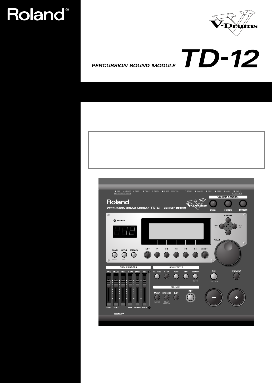
Owner’s Manual
We’d like to take a moment to thank you for purchasing the Roland Percussion Sound Module TD-12.
201b
Before using this unit, carefully read the sections entitled: “IMPORTANT SAFETY
INSTRUCTIONS” (p. 2), “USING THE UNIT SAFELY” (p. 3), and “IMPORTANT NOTES”
(p. 5). These sections provide important information concerning the proper operation
of the unit. Additionally, in order to feel assured that you have gained a good grasp
of every feature provided by your new unit, Owner’s manual should be read in its
entirety. The manual should be saved and kept on hand as a convenient reference.
202
Copyright © 2005 ROLAND CORPORATION
All rights reserved. No part of this publication may be reproduced in any form without the
written permission of ROLAND CORPORATION.
Page 2
WARNING: To reduce the risk of fire or electric shock, do not expose this apparatus to rain or moisture.
CAUTION
RISK OF ELECTRIC SHOCK
DO NOT OPEN
ATTENTION: RISQUE DE CHOC ELECTRIQUE NE PAS OUVRIR
CAUTION: TO REDUCE THE RISK OF ELECTRIC SHOCK,
DO NOT REMOVE COVER (OR BACK).
NO USER-SERVICEABLE PARTS INSIDE.
REFER SERVICING TO QUALIFIED SERVICE PERSONNEL.
The lightning flash with arrowhead symbol, within an
equilateral triangle, is intended to alert the user to the
presence of uninsulated “dangerous voltage” within the
product’s enclosure that may be of sufficient magnitude to
constitute a risk of electric shock to persons.
The exclamation point within an equilateral triangle is
intended to alert the user to the presence of important
operating and maintenance (servicing) instructions in the
literature accompanying the product.
INSTRUCTIONS PERTAINING TO A RISK OF FIRE, ELECTRIC SHOCK, OR INJURY TO PERSONS.
IMPORTANT SAFETY INSTRUCTIONS
SAVE THESE INSTRUCTIONS
WARNING - When using electric products, basic precautions should always be followed, including the following:
1. Read these instructions.
2. Keep these instructions.
3. Heed all warnings.
4. Follow all instructions.
5. Do not use this apparatus near water.
6. Clean only with a dry cloth.
7. Do not block any of the ventilation openings. Install in
accordance with the manufacturers instructions.
8. Do not install near any heat sources such as radiators,
heat registers, stoves, or other apparatus (including
amplifiers) that produce heat.
9. Do not defeat the safety purpose of the polarized or
grounding-type plug. A polarized plug has two blades with
one wider than the other. A grounding type plug has two
blades and a third grounding prong. The wide blade or the
third prong are provided for your safety. If the provided plug
does not fit into your outlet, consult an electrician for
replacement of the obsolete outlet.
10. Protect the power cord from being walked on or pinched
particularly at plugs, convenience receptacles, and the
point where they exit from the apparatus.
11. Only use attachments/accessories specified
by the manufacturer.
12. Unplug this apparatus during lightning storms or when
unused for long periods of time.
13. Refer all servicing to qualified service personnel. Servicing
is required when the apparatus has been damaged in any
way, such as power-supply cord or plug is damaged, liquid
has been spilled or objects have fallen into the apparatus,
the apparatus has been exposed to rain or moisture, does
not operate normally, or has been dropped.
For the U.K.
WARNING:
IMPORTANT:
As the colours of the wires in the mains lead of this apparatus may not correspond with the coloured markings identifying
the terminals in your plug, proceed as follows:
The wire which is coloured GREEN-AND-YELLOW must be connected to the terminal in the plug which is marked by the
letter E or by the safety earth symbol or coloured GREEN or GREEN-AND-YELLOW.
The wire which is coloured BLUE must be connected to the terminal which is marked with the letter N or coloured BLACK.
The wire which is coloured BROWN must be connected to the terminal which is marked with the letter L or coloured RED.
THIS APPARATUS MUST BE EARTHED
THE WIRES IN THIS MAINS LEAD ARE COLOURED IN ACCORDANCE WITH THE FOLLOWING CODE.
GREEN-AND-YELLOW: EARTH, BLUE: NEUTRAL, BROWN: LIVE
2
Page 3

USING THE UNIT SAFELY
Used for instructions intended to alert
the user to the risk of death or severe
injury should the unit be used
improperly.
Used for instructions intended to alert
the user to the risk of injury or material
damage should the unit be used
improperly.
* Material damage refers to damage or
other adverse effects caused with
respect to the home and all its
furnishings, as well to domestic
animals or pets.
001
• Before using this unit, make sure to read the
instructions below, and the Owner’s Manual.
................................................................................................
001-50
• Connect mains plug of this model to a mains
socket outlet with a protective earthing connection.
................................................................................................
002a
• Do not open or perform any internal modifications
on the unit.
................................................................................................
003
• Do not attempt to repair the unit, or replace parts
within it (except when this manual provides
specific instructions directing you to do so). Refer
all servicing to your retailer, the nearest Roland
Service Center, or an authorized Roland
distributor, as listed on the “Information” page.
................................................................................................
004
• Never use or store the unit in places that are:
• Subject to temperature extremes (e.g., direct
sunlight in an enclosed vehicle, near a heating
duct, on top of heat-generating equipment); or
are
• Damp (e.g., baths, washrooms, on wet floors); or
are
• Humid; or are
• Exposed to rain; or are
• Dusty; or are
• Subject to high levels of vibration.
................................................................................................
007
• Make sure you always have the unit placed so it is
level and sure to remain stable. Never place it on
stands that could wobble, or on inclined surfaces.
................................................................................................
The symbol alerts the user to important instructions
or warnings.The specific meaning of the symbol is
determined by the design contained within the
triangle. In the case of the symbol at left, it is used for
general cautions, warnings, or alerts to danger.
The symbol alerts the user to items that must never
be carried out (are forbidden). The specific thing that
must not be done is indicated by the design contained
within the circle. In the case of the symbol at left, it
means that the unit must never be disassembled.
The ● symbol alerts the user to things that must be
carried out. The specific thing that must be done is
indicated by the design contained within the circle. In
the case of the symbol at left, it means that the powercord plug must be unplugged from the outlet.
008a
• The unit should be connected to a power supply
only of the type described in the operating instructions, or as marked on the bottom of unit.
................................................................................................
008e
• Use only the attached power-supply cord. Also,
the supplied power cord must not be used with
any other device.
................................................................................................
009
• Do not excessively twist or bend the power cord,
nor place heavy objects on it. Doing so can damage
the cord, producing severed elements and short
circuits. Damaged cords are fire and shock hazards!
................................................................................................
010
• This unit, either alone or in combination with an
amplifier and headphones or speakers, may be
capable of producing sound levels that could cause
permanent hearing loss. Do not operate for a long
period of time at a high volume level, or at a level
that is uncomfortable. If you experience any
hearing loss or ringing in the ears, you should
immediately stop using the unit, and consult an
audiologist.
................................................................................................
011
• Do not allow any objects (e.g., flammable material,
coins, pins); or liquids of any kind (water, soft
drinks, etc.) to penetrate the unit.
................................................................................................
3
Page 4
012a
• Immediately turn the power off, remove the power
cord from the outlet, and request servicing by your
retailer, the nearest Roland Service Center, or an
authorized Roland distributor, as listed on the
“Information” page when:
• The power-supply cord, or the plug has been
damaged; or
• If smoke or unusual odor occurs
• Objects have fallen into, or liquid has been
spilled onto the unit; or
• The unit has been exposed to rain (or otherwise
has become wet); or
• The unit does not appear to operate normally or
exhibits a marked change in performance.
................................................................................................
013
• In households with small children, an adult should
provide supervision until the child is capable of
following all the rules essential for the safe
operation of the unit.
................................................................................................
014
• Protect the unit from strong impact.
(Do not drop it!)
................................................................................................
015
• Do not force the unit’s power-supply cord to share
an outlet with an unreasonable number of other
devices. Be especially careful when using extension
cords—the total power used by all devices you
have connected to the extension cord’s outlet must
never exceed the power rating (watts/amperes) for
the extension cord. Excessive loads can cause the
insulation on the cord to heat up and eventually
melt through.
................................................................................................
016
• Before using the unit in a foreign country, consult
with your retailer, the nearest Roland Service
Center, or an authorized Roland distributor, as
listed on the “Information” page.
................................................................................................
026
• Do not put anything that contains water (e.g.,
flower vases) on this unit. Also, avoid the use of
insecticides, perfumes, alcohol, nail polish, spray
cans, etc., near the unit. Swiftly wipe away any
liquid that spills on the unit using a dry, soft cloth.
................................................................................................
101a
• The unit should be located so that its location or
position does not interfere with its proper ventilation.
................................................................................................
102b
• Always grasp only the plug on the power-supply
cord when plugging into, or unplugging from, an
outlet or this unit.
................................................................................................
103a
• At regular intervals, you should unplug the power
plug and clean it by using a dry cloth to wipe all
dust and other accumulations away from its
prongs. Also, disconnect the power plug from the
power outlet whenever the unit is to remain
unused for an extended period of time. Any
accumulation of dust between the power plug and
the power outlet can result in poor insulation and
lead to fire.
................................................................................................
104
• Try to prevent cords and cables from becoming
entangled. Also, all cords and cables should be
placed so they are out of the reach of children.
................................................................................................
106
• Never climb on top of, nor place heavy objects on
the unit.
................................................................................................
107b
• Never handle the power cord or its plugs with wet
hands when plugging into, or unplugging from, an
outlet or this unit.
................................................................................................
108a
• Before moving the unit, disconnect the power plug
from the outlet, and pull out all cords from
external devices.
................................................................................................
109a
• Before cleaning the unit, turn off the power and
unplug the power cord from the outlet.
................................................................................................
110a
• Whenever you suspect the possibility of lightning
in your area, pull the plug on the power cord out
of the outlet.
................................................................................................
118a
• Should you remove screws from the bottom panel
of the unit (p. 16), keep them in a safe place out of
children’s reach, so there is no chance of them
being swallowed accidentally.
................................................................................................
4
Page 5

IMPORTANT NOTES
291b
In addition to the items listed under “IMPORTANT SAFETY INSTRUCTIONS” and “USING THE UNIT
SAFELY” on pages 2–4, please read and observe the following:
Power Supply
301
• Do not connect this unit to same electrical outlet that is
being used by an electrical appliance that is controlled by
an inverter (such as a refrigerator, washing machine,
microwave oven, or air conditioner), or that contains a
motor. Depending on the way in which the electrical
appliance is used, power supply noise may cause this unit
to malfunction or may produce audible noise. If it is not
practical to use a separate electrical outlet, connect a power
supply noise filter between this unit and the electrical
outlet.
307
• Before connecting this unit to other devices, turn off the
power to all units. This will help prevent malfunctions
and/or damage to speakers or other devices.
308
• Although the LCD and LEDs are switched off when the
POWER switch is switched off, this does not mean that the
unit has been completely disconnected from the source of
power. If you need to turn off the power completely, first
turn off the POWER switch, then unplug the power cord
from the power outlet. For this reason, the outlet into
which you choose to connect the power cord’s plug should
be one that is within easy reach and readily accessible.
Placement
351
• Using the unit near power amplifiers (or other equipment
containing large power transformers) may induce hum. To
alleviate the problem, change the orientation of this unit; or
move it farther away from the source of interference.
352a
• This device may interfere with radio and television
reception. Do not use this device in the vicinity of such
receivers.
352b
• Noise may be produced if wireless communications
devices, such as cell phones, are operated in the vicinity of
this unit. Such noise could occur when receiving or initiating a call, or while conversing. Should you experience
such problems, you should relocate such wireless devices
so they are at a greater distance from this unit, or switch
them off.
355b
• When moved from one location to another where the
temperature and/or humidity is very different, water
droplets (condensation) may form inside the unit. Damage
or malfunction may result if you attempt to use the unit in
this condition. Therefore, before using the unit, you must
allow it to stand for several hours, until the condensation
has completely evaporated.
Maintenance
401a
• For everyday cleaning wipe the unit with a soft, dry cloth
or one that has been slightly dampened with water. To
remove stubborn dirt, use a cloth impregnated with a mild,
non-abrasive detergent. Afterwards, be sure to wipe the
unit thoroughly with a soft, dry cloth.
402
• Never use benzine, thinners, alcohol or solvents of any
kind, to avoid the possibility of discoloration and/or deformation.
Repairs and Data
452
• Please be aware that all data contained in the unit’s
memory may be lost when the unit is sent for repairs.
Important data should always be backed up in another
MIDI device (e.g., a sequencer), or written down on paper
(when possible). During repairs, due care is taken to avoid
the loss of data. However, in certain cases (such as when
circuitry related to memory itself is out of order), we regret
that it may not be possible to restore the data, and Roland
assumes no liability concerning such loss of data.
Memory Backup
501b
• This unit contains a battery which powers the unit’s
memory circuits while the main power is off. When this
battery becomes weak, the message shown below will
appear in the display. Once you see this message, have the
battery replaced with a fresh one as soon as possible to
avoid the loss of all data in memory. To have the battery
replaced, consult with your retailer, the nearest Roland
Service Center, or an authorized Roland distributor, as
listed on the “Information” page.
“Backup Battery Low!”
5
Page 6

IMPORTANT NOTES
Additional Precautions
551
• Please be aware that the contents of memory can be
irretrievably lost as a result of a malfunction, or the
improper operation of the unit. To protect yourself against
the risk of loosing important data, we recommend that you
periodically save a backup copy of important data you
have stored in the unit’s memory in another MIDI device
(e.g., a sequencer).
552
• Unfortunately, it may be impossible to restore the contents
of data that was stored in the unit’s memory or in another
MIDI device (e.g., a sequencer) once it has been lost.
Roland Corporation assumes no liability concerning such
loss of data.
553
• Use a reasonable amount of care when using the unit’s
buttons, sliders, or other controls; and when using its jacks
and connectors. Rough handling can lead to malfunctions.
554
• Never strike or apply strong pressure to the display.
556
• When connecting / disconnecting all cables, grasp the
connector itself—never pull on the cable. This way you will
avoid causing shorts, or damage to the cable’s internal
elements.
557
• A small amount of heat will radiate from the unit during
normal operation.
558a
• To avoid disturbing your neighbors, try to keep the unit’s
volume at reasonable levels. You may prefer to use
headphones, so you do not need to be concerned about
those around you (especially when it is late at night).
558c
• Since sound vibrations can be transmitted through floors
and walls to a greater degree than expected, take care not
to allow such sound to become a nuisance to neighbors,
especially at night and when using headphones. Although
the drum pads and pedals are designed so there is a
minimal amount of extraneous sound produced when
they’re struck, rubber heads tend to produce louder
sounds compared to mesh heads. You can effectively
reduce much of the unwanted sound from the pads by
switching to mesh heads.
559a
• When you need to transport the unit, package it in the box
(including padding) that it came in, if possible. Otherwise,
you will need to use equivalent packaging materials.
562
• Use a cable from Roland to make the connection. If using
some other make of connection cable, please note the
following precautions.
• Some connection cables contain resistors. Do not use
cables that incorporate resistors for connecting to this
unit. The use of such cables can cause the sound level to
be extremely low, or impossible to hear. For information on cable specifications, contact the manufacturer of the cable.
6
Page 7

Contents
USING THE UNIT SAFELY ........................................................................3
IMPORTANT NOTES..................................................................................5
Features ...................................................................................................11
Panel Descriptions ..................................................................................13
Top Panel............................................................................................................................. 13
Rear Panel ...........................................................................................................................15
Setting Up the Kit ....................................................................................16
Mounting the TD-12 on the Stand ...................................................................................16
Connecting the Pads and Pedals...................................................................................... 17
Connecting Headphones, Audio Equipment, Amps, or Other Gear .........................18
Turning On/Off the Power ..............................................................................................19
Connecting the Hi-Hat (VH-11) and Setting the “VH Offset” ....................................20
Connecting the Hi-Hat ............................................................................................................................ 20
Adjusting the Offset................................................................................................................................. 20
Adjusting Mesh Head Tension ........................................................................................21
Adjusting the PD-105 Head Tension ..................................................................................................... 21
Adjusting the PD-85 Head Tension ....................................................................................................... 21
Playing Methods......................................................................................22
Pad (PD-105/PD-85)..........................................................................................................22
Change the Nuance of the Rim Shot...................................................................................................... 22
Brush Sweeps ............................................................................................................................................ 22
Cymbal (CY-12R/C) ..........................................................................................................22
Choke Play................................................................................................................................................. 23
Positional Sensing..................................................................................................................................... 23
Hi-Hat (VH-11/VH-12).....................................................................................................23
Button Operation and Displays..............................................................24
Saving Your Settings..........................................................................................................24
Buttons, Sliders, Dial and Knobs .....................................................................................24
Cursor ..................................................................................................................................24
Function Buttons ([F1]–[F5])............................................................................................. 24
Changing Data Values.......................................................................................................24
Choosing Pads from the TD-12’s Top Panel ..................................................................25
Convenient [PREVIEW] Functions ........................................................................................................ 25
How to Play Patterns.........................................................................................................25
How to Turn the Metronome (Click) On/Off................................................................ 25
How to Adjust the Tempo ................................................................................................26
Adjusting the Display Contrast .......................................................................................26
About the Display in the Upper Right of the Screen ....................................................26
Group Faders...................................................................................................................... 26
Listening to the Demo Song...................................................................27
Changing the Drum Kits...................................................................................................27
Changing the Volume Balance.........................................................................................27
Muting the Performance of the Backing Instruments and Drums .............................27
Turning the Metronome (Click) On/Off ........................................................................27
7
Page 8

Contents
Useful Functions to Know ......................................................................28
About the Preset Drum Kits .............................................................................................28
Playing Patterns to Check Drum Kit Tones ...................................................................28
Restoring Edited Drum Kits to the Factory Default Settings ......................................28
Restoring All Settings to the Factory Settings...................................................................................... 28
Restoring the Factory Settings to Individual Kits................................................................................ 28
Playing Back Patterns by Striking the Pads (Pad Pattern Function) ..........................29
Stopping Playback of the Pattern Being Played...................................................................................29
Disabling the Pad Pattern Function....................................................................................................... 29
Striking a Pad to Switch the Drum Kits (Pad Switch Function)..................................29
Enabling Cross Sticks ........................................................................................................29
Playing Along with Patterns ............................................................................................29
Choosing a Pattern ................................................................................................................................... 29
Muting a Specific Part.............................................................................................................................. 29
Chapter 1. Drum Kit Settings [KIT] ........................................................30
Choosing a Drum Kit.........................................................................................................30
About the “DRUM KIT” Screen ............................................................................................................. 30
Selecting a Drum Kit from the List [F1 (LIST)].............................................................. 31
Kit Parameters [F2 (FUNC)] .............................................................................................31
Adjusting the Volume [F1 (VOLUME)] ................................................................................................31
Assigning a Tempo for Each Kit [F2 (TEMPO)]................................................................................... 31
Playing Brushes [F3 (BRUSH)] ............................................................................................................... 32
Disabling the Pad Pattern Function [F4 (PAD PTN)] ......................................................................... 32
Naming a Drum Kit [F3 (NAME)]................................................................................... 32
Effects On and Off Switches [F4 (FX SW)] .....................................................................32
Playing Cross Stick [F5 (XSTICK)]...................................................................................32
Chapter 2. Drum Instrument Settings [INST] ........................................33
Choosing a Pad to Edit......................................................................................................33
Choose by Hitting a Pad.......................................................................................................................... 33
Choose with the Buttons .........................................................................................................................33
Lock the Pad You are Editing (TRIG LOCK) [SHIFT] + [RIM] ......................................................... 33
Assign an Instrument to a Pad.........................................................................................33
Selecting an Instrument from the List [F1 (LIST)].........................................................34
Editing Drum Sounds [F2 (EDIT)]................................................................................... 34
Editing an Acoustic Drum Kit (V-EDIT)............................................................................................... 34
Editing Other Instruments ...................................................................................................................... 34
Editing Procedure..................................................................................................................................... 34
Using the Compressor and EQ [F3 (COMP/EQ)]......................................................... 36
Using Pads/Pedal as Controllers [F4 (CONTROL)]..................................................... 37
Playing a Pattern by Hitting a Pad (Pad Pattern) [F1 (PATTERN)].................................................. 37
Changing the Pitch with the Hi-Hat Pedal [F2 (PDLBEND)] ............................................................ 38
MIDI Settings for Each Pad [F3 (MIDI)]................................................................................................ 38
MIDI Note Numbers transmitted by Hi-Hat [F4 (HH MIDI)]........................................................... 38
MIDI Note Number transmitted by Brush Sweep/Cross Stick [F5 (BR MIDI)] .............................38
Chapter 3. Mixer Settings .......................................................................39
Mixer Parameters [MIXER] ..............................................................................................39
Using Group Faders to Edit (MIX EDIT) ..............................................................................................39
8
Page 9

Contents
Chapter 4. Effect Settings.......................................................................40
Effects On and Off Switches [KIT] - [F4 (FX SW)].........................................................40
Using the Compressor and EQ [INST] - [F3 (COMP/EQ)]..........................................40
Compressor (COMP) ...............................................................................................................................41
Equalizer (EQ)........................................................................................................................................... 41
Ambience [AMBIENCE] ...................................................................................................42
Multi-Effects [SHIFT] + [AMBIENCE]............................................................................ 42
Multi-Effects Parameters......................................................................................................................... 43
Chapter 5. Trigger Settings [TRIGGER].................................................44
Selecting the Pad Type [F1 (BANK)]............................................................................... 44
Trigger Inputs and Pad/Playing Methods corresponding chart ......................................................44
Setting the Pad Sensitivity [F2 (BASIC)]......................................................................... 45
Pad Sensitivity ..........................................................................................................................................45
Minimum level for the pad (Threshold) ...............................................................................................45
How Playing Dynamics Changes the Volume (Velocity Curve) ......................................................45
Hi-Hat Settings [F3 (HI-HAT)].........................................................................................46
Connecting the VH-11 and Adjusting the TD-12................................................................................. 47
Connecting the VH-12 and Adjusting the TD-12................................................................................. 48
Connecting and Setting the Hi-Hat Control Pedal (FD Series).......................................................... 48
Eliminate Crosstalk Between Pads [F4 (XTALK)]......................................................... 49
Advanced Trigger Parameters [F5 (ADVANCE)].........................................................50
Trigger Signal Detection Time (Scan Time).......................................................................................... 50
Detecting Trigger Signal Attenuation (Retrigger Cancel) .................................................................. 50
Double Triggering Prevention (Mask Time) ........................................................................................51
Rim/Edge Dynamic Response (Rim Gain)........................................................................................... 51
Rim Shots Response (Rim Shot Adjust) ................................................................................................51
Cross Stick Threshold (XStick Thrshld) ................................................................................................51
Playing Bow, Bell, and Edge (3-Way Triggering)................................................................................ 52
Naming a Trigger Bank [F5 (Name)]..................................................................................................... 52
Chapter 6. Sequencer (Playback)...........................................................53
Basic Operation ..................................................................................................................53
Choosing a Pattern [PATTERN] ......................................................................................54
About the “PATTERN” screen ............................................................................................................... 54
Select a Pattern from the List [F1 (LIST)]........................................................................54
Playing Back a Pattern [PLAY] ........................................................................................54
Tempo Adjustment ............................................................................................................ 55
Setting the Tempo by Hitting a Pad (Tap Tempo) ..............................................................................55
Synchronizing with an External MIDI Device .....................................................................................55
Part Settings [F2 (PART)].................................................................................................. 56
Make Settings for the Backing Part [F1 (BACKING)] .........................................................................56
Master Tuning........................................................................................................................................... 56
Percussion Part Settings [F2 (PERC)] .................................................................................................... 57
Percussion Set Settings ............................................................................................................................57
Volume/Pan Settings for Each Part [F3 (MIXER)] ..............................................................................59
Reverb Settings for Backing Parts [F3 (MIXER)] - [F4 (REVERB)] .................................................... 59
Muting a Specific Part [F5 (MUTE)] ......................................................................................................60
Pattern Settings [F3 (FUNC)]............................................................................................60
Time Signature/Number of Measures/Tempo Settings [F1 (SETUP)]............................................ 60
Choosing a Playback Method [F2 (TYPE)] ...........................................................................................61
Confirming the Usage Status of the TD-12’s Internal Memory [F3 (MEMORY)]........................... 61
Naming a Pattern [F5 (NAME)] .............................................................................................................62
Starting and Stopping the Metronome (Click) On/Off................................................62
Using a Indicator as a Click (Tempo Indicator)............................................................. 62
Setting the Click .................................................................................................................63
9
Page 10

Contents
Chapter 7. Sequencer (Recording/Editing) ...........................................64
Recording a Pattern [REC]................................................................................................ 64
How to Record.......................................................................................................................................... 64
Checking the Tones and Phrases During Recording (Rehearsal)...................................................... 66
Editing a Pattern [F4 (EDIT)]............................................................................................ 67
Copying a Pattern [F1 (COPY)] .............................................................................................................. 67
Connecting Two Patterns [F2 (APPEND)]............................................................................................ 68
Erasing a pattern [F3 (ERASE)] ..............................................................................................................68
Deleting a Pattern [F4 (DELETE)] .......................................................................................................... 69
Chapter 8. Copy Function [COPY] .........................................................70
About Copied Settings............................................................................................................................. 71
Chapter 9. Settings for the Entire TD-12 [SETUP]................................72
MIDI Settings and Operations [F1 (MIDI)] ....................................................................72
Setting the MIDI Channels for Each Part [F1 (MIDI CH)].................................................................. 72
MIDI Settings for the Entire TD-12 [F2 (GLOBAL)]............................................................................ 72
MIDI Messages for Detailed Performance Expressions [F3 (CTRL)]................................................ 74
Switching Drum Kits via MIDI (Program Change) [F4 (PROG)]...................................................... 74
Saving Data to an external MIDI Device (Bulk Dump) [F5 (BULK)]................................................ 75
Selecting Output Destinations [F2 (OUTPUT)] .............................................................76
Output Destination for the Drum Instruments.................................................................................... 76
Output Destination for the Sequencer Parts/Metronome Click/
Sound Input from MIX IN [F2 (OTHER)]............................................................................................. 76
Setting the Switches [F3 (CONTROL)] ...........................................................................76
Using Pads as Switches [F1 (PAD SW)] ................................................................................................76
PREVIEW Button Velocity [F2 (PREVIEW)] ........................................................................................77
Adjusting the Display Contrast [F3 (LCD)].......................................................................................... 77
Checking the TD-12’s Internal Program Version [F5 (VERSION)] ................................................... 77
Synchronizing Images to a TD-12 Performance [F4 (V-LINK)] ..................................78
What is V-LINK? ......................................................................................................................................78
Connection Examples ..............................................................................................................................78
Using V-LINK ........................................................................................................................................... 78
Restoring the Factory Settings [F5 (F RESET)]............................................................... 79
Chapter 10. Drum Kit Chain [CHAIN].....................................................80
Creating a Drum Kit Chain ..............................................................................................80
Naming a Drum Kit Chain [F5 (NAME)] .............................................................................................81
Playing with a Drum Kit Chain .......................................................................................81
Messages and Error Messages..............................................................82
Preset Drum Kit List................................................................................84
Preset Pattern List...................................................................................86
Drum Instrument List ..............................................................................88
Preset Percussion Set List .....................................................................92
Backing Instrument List..........................................................................94
MIDI Implementation Chart.....................................................................96
Specifications ..........................................................................................98
Block Diagram .......................................................................................100
Index .......................................................................................................102
10
Page 11
Features
Everything Is New! Module—
Stand—V-Hi-Hat—Pads
The TD-12 follows in the foot steps of the TD-20, taking
advantage of Roland’s powerful COSM technology. Velocity,
position, and interval of each hit are detected precisely,
providing real and natural dynamics. The new, dual trigger
PD-105/85 pads give you superior feel, response and control
of the sound. You can play both shallow and deep rim shots.
12 trigger inputs let you use lots of pads, leaving room for
advanced Pad Switch applications. (p. 76)
* COSM (Composite Object Sound Modeling) is a Roland
technology combining multiple sound modeling processes to
create new sounds.
* Positional detection is possible on snare drums (head/rim),
toms (rim) and ride cymbals (bow).
560 New Drum Sounds
Expanded V-Editing
The onboard sound library was created for the TD-12, and
designed to work with enhanced V-Editing. Besides being able
to change heads, muffling types, shell depth, etc. you can also
place sizzles on any cymbal, and add snare buzz to the toms
or kick.
High-speed triggering
Overview
Advances in trigger technology combined with new pad
designs and V-Hi-Hat pads, provide natural response and
feel. Even playing with brushes (plastic only) has improved
(p. 32).
Audio Signal Routing Stage
or Studio
Flexibility of audio routing is important in the professional
environment. The TD-12 lets you use all of the outputs in a
very efficient way. Each sound of the drum kit can be assigned
to one of the 4 individual outs. (Master out can be used as an
individual pair. The Effects, Ambience, Backing parts, Click
and even audio coming in the MIX input, can be assigned to
individual outputs. Perfect for any situation.
V-Hi-Hat Compatibility
By including the VH-11 V-Hi-Hat, which features a single-
piece construction, you can perform with a natural feel. Using
the VH-12 two-piece hi-hat, you can use pressure on the pedal
when the hi-hat is closed to create further changes in the
nuance and/or pitch of the sound (p. 23).
An Easy User Interface
The interface is very easy to navigate. With the many buttons
on the top panel, you won’t lose time searching for functions.
Clear graphics, icons and menus guide you through the
simple and complex operations. No matter where you are
inside the TD-12, pushing the KIT button always brings you
back to the main kit page. Even still, please read this manual.
Cables Are Easy To Organize
The MDS-12 stand allows you to pass the cables through the
pipes, making easy to transport and set up again. It
streamlines the look as well.
11
Page 12
Features
Top Quality Signal
Processing
Each instrument assigned to trigger 1–12 head and rim inputs
has an individual three-band equalizer and compressor (p.
40). There is also a multi-effects unit with delays, flanger,
chorus, and phaser (p. 42). There’s also Ambience, with a new
room “shape” feature in addition to being able to change wall
materials, size, etc. (p. 42) All effects are simple to understand
and use. Via the top panel, you can also turn all the effects on
or off individually.
Functions For Stage
The group faders on the top panel let you make quick changes
as needed during performance (p. 26). You can play drum kits
in any desired order (Drum Kit Chain, p. 80). The +/- buttons
are large enough to be pressed with a drum stick. (Don’t HIT
them!) Another very useful function allows you to send the
click sound ONLY to the headphones if desired (p. 76). An
audio input (stereo) for custom monitoring (MIX IN jack, p.
18) is also provided. The MIX EDIT function allows immediate
editing of volume, Ambience send level, and MFX send level
using the group faders (p. 39).
Sequencer
Advanced Tempo Functions
Each KIT can have it’s own tempo setting. The visual indicator
helps you count off the tempo of a song without needing to
hear the click (p. 62). Tap Tempo function allows you to set
tempo from all trigger inputs or the preview button (p. 55).
MIDI Sound Module
Potentials
Percussion sets are accessed on a different MIDI channel than
the drums. They can be played from the internal sequencer or
external MIDI source (SPD type pad etc.) and feature a 128
note map. And with 262 backing instruments available, there
are sounds for all types of music (p. 94).
V-LINK function
V-LINK ( ) is a function that allows music and
images to be performed together. By using MIDI to connect
two or more V-LINK compatible devices, you can easily enjoy
performing a wide range of visual effects that are linked to the
expressive elements of a music performance. By using the TD-
12 and Edirol DV-7PR together, connected pads can be used to
switch the Edirol DV-7PR’s images (clips/palettes) (p. 78).
Recording and playing back patterns is very easy. The 6 part
backing section, (including drums) can be used for live or
recording performances. Recording directly from the pads to
the percussion part is a great new feature, too (p. 73).
12
Page 13
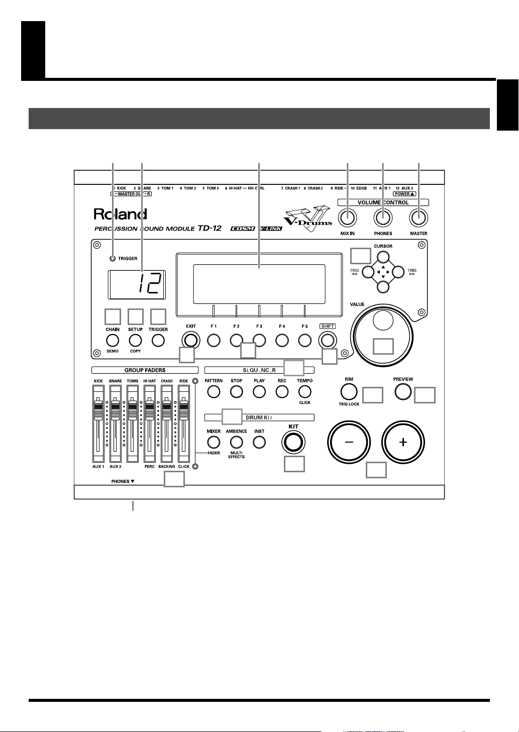
Panel Descriptions
Top Panel
fig.top
4
Overview
21
3 14 15 16
17
65
7
8
9
18
11
19
20
12
10
22
1.
Trigger Indicator
This lights up each time a trigger signal is received from a
pad. It monitors the pad connection and is helpful when
customizing trigger parameters.
2.
LED Display
Displays the Kit number (currently selected drum kit).
3.
Graphic Display
During normal performance, you see the kit name and
other information. When editing, relative graphics and
text will appear depending on the edit mode you are in.
* In this owner’s manual, this will be referred to as “the display.”
13
4.
CHAIN Button
A Chain allows you to set up a customized order for
playing your kits. There are 16 Chains (32 steps each).
Chains can be named also (p. 80).
5.
SETUP (COPY) Button
For access to functions that affect the TD-12 globally,
such as MIDI parameters etc. (p. 72)
You can copy drum kit, instrument, and other settings by
pressing this button together with the SHIFT button (p.
70).
21
13
Page 14

Panel Descriptions
6.
TRIGGER Button
For access to trigger parameters (p. 44).
7.
EXIT Button
Press this to return to the previous screen. Repeated
pressing takes you back to the “DRUM KIT” screen.
8.
F1–F5 Buttons (Function Buttons)
These buttons change their function depending on the
contents of the display. The lower part of the display will
indicate the function of each button (p. 24).
9.
SHIFT Button
Used in combination with other buttons. How this
functions is explained in respective parts of this manual.
10.
GROUP FADERS
The faders are switchable, allowing you to adjust the
volume of the kick, snare, toms, hi-hat, cymbals,
percussion and backing instruments, and the click sound
(p. 26).
11.
SEQUENCER
These provide access to and control of sequencer
functions (pattern playback/recording, Percussion set)
etc. (p. 53, p. 64)
12.
DRUM KIT
These buttons take you to the screens for creating or
editing a drum kit. (p. 33, p. 39, p. 40).
13.
KIT Button
One touch brings you back to the basic display screen. It
works from any Edit mode as well.
14.
MIX IN Knob
Adjusts the level of the audio source connected to the
MIX IN jack. This sound is output from the MASTER
OUT jacks and/or the PHONES jack. Other possibilities
(p. 76).
17.
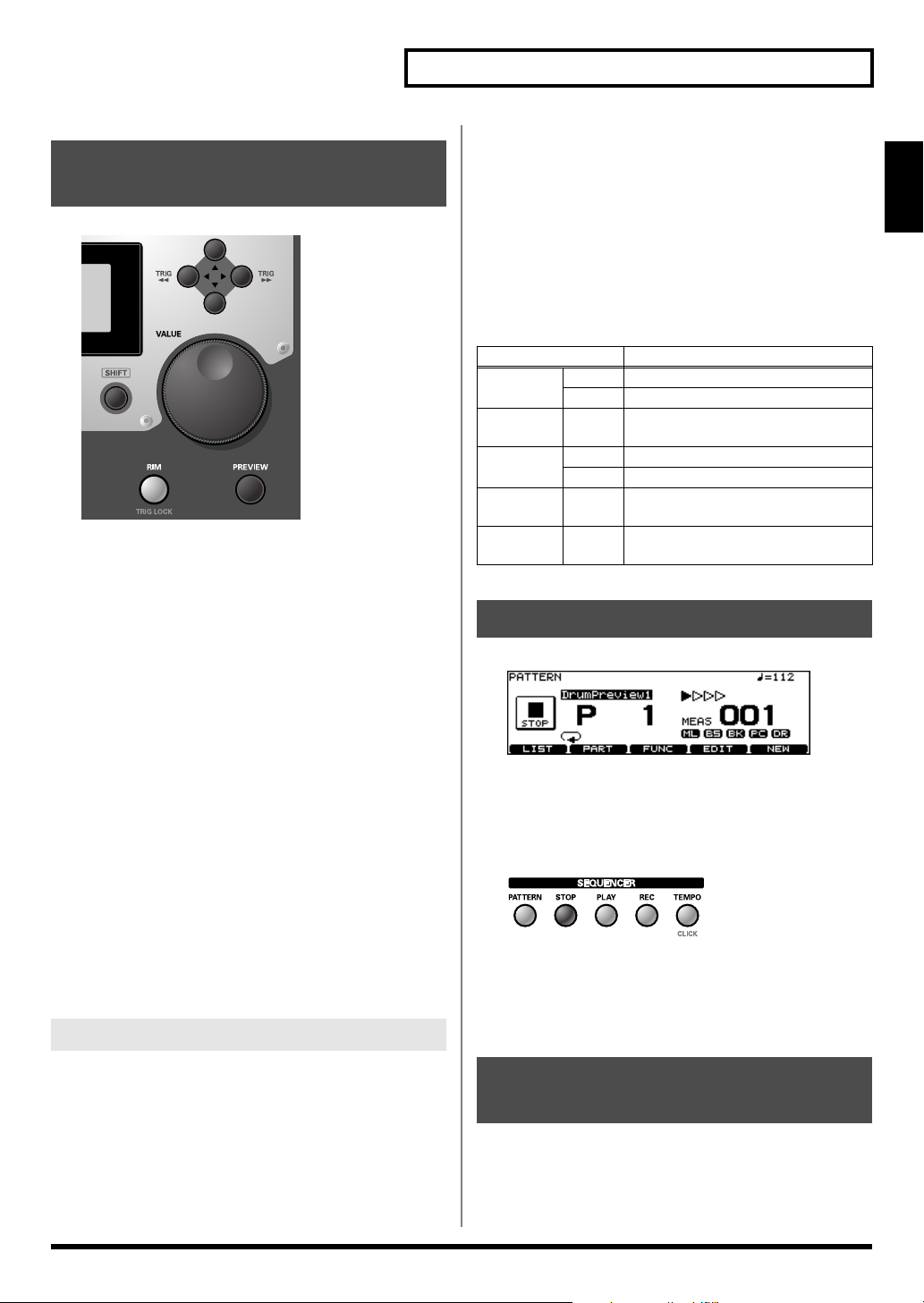
CURSOR (TRIG) Buttons
Used to move the cursor in the display (p. 24).
You can select the pad (trigger number) you want to
make settings for by pressing this button together with
the SHIFT button. You can also use the PREVIEW button
to check the sound of the instrument assigned to the
selected pad.
* When you connect a pad to the TD-12, you can then tap the
pad to select it as the pad for which settings are made.
18.
VALUE Dial
This dial functions like the + and - buttons. Use it to scroll
quickly or make large changes in edited values (p. 24).
19.
RIM (TRIG LOCK) Button
Press this to select the rim of a pad. (RIM button lights.)
(p. 25).
By pressing this button together with the SHIFT button,
you can prevent the screen from being switched
inadvertently even if you hit another pad when editing
instruments (Trigger Lock; p. 33).
20.
PREVIEW Button
This button allows you to audition an instrument after
you have chosen it with the CURSOR (TRIG) buttons or
after you have played a pad/pedal (p. 25).
21.
+ Button, - Button
These buttons are used to switch drum kits or to change
values when editing. The + button increases the value,
and the - button decreases it (p. 24). You can also use the
tip of your drum stick to press them.
* Never hit them with a stick as this can cause malfunctions.
22.
PHONES Jack
A pair of stereo headphones can be connected to this jack.
Connecting the headphones will not mute the output
from the MASTER OUT jacks (p. 18).
15.
PHONES Knob
Adjusts the headphone volume. Plugging in headphones
does not affect the master output (like other audio
device.)
16.
MASTER Knob
Adjusts the volume of the MASTER OUT jacks.
14
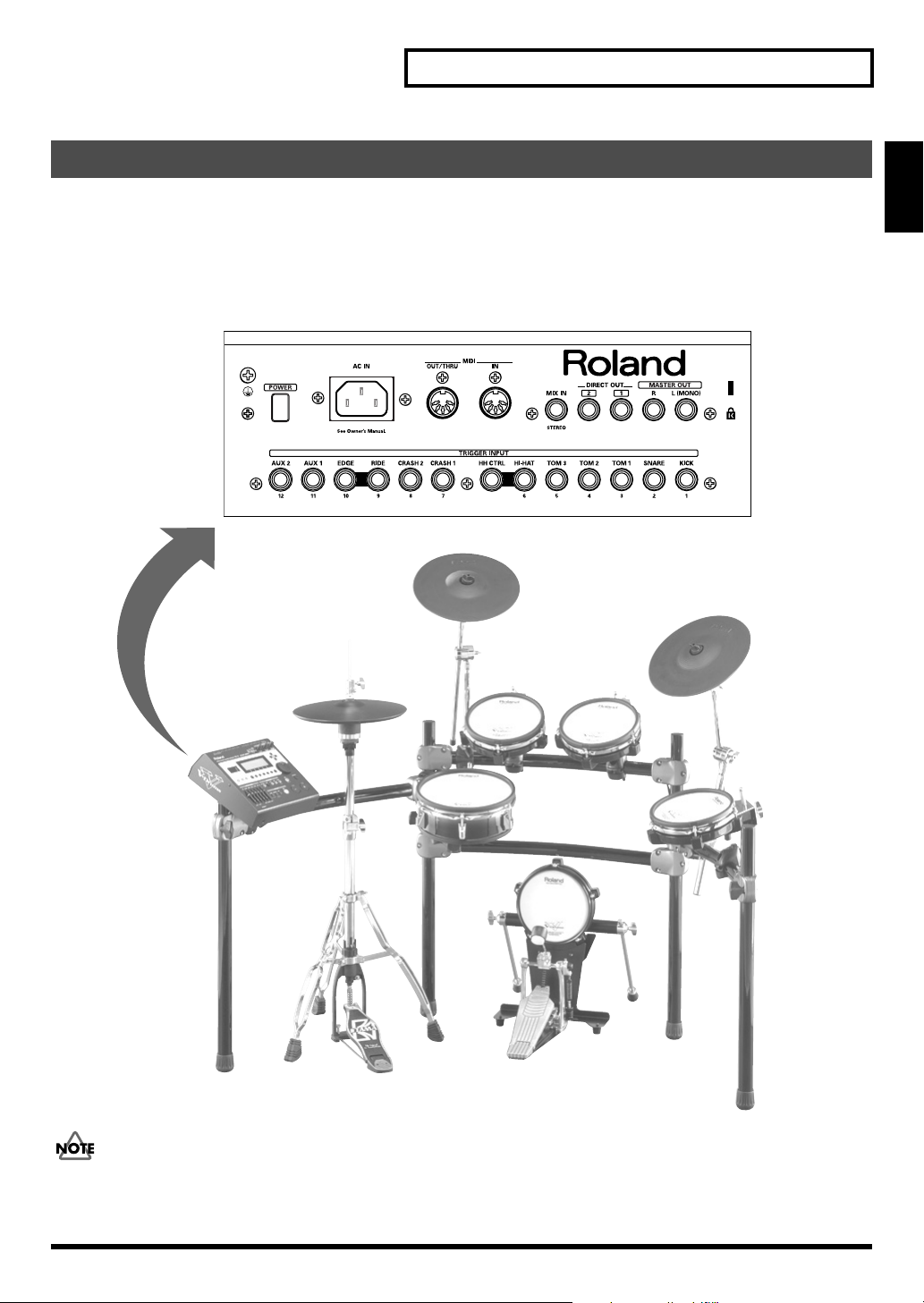
Page 15
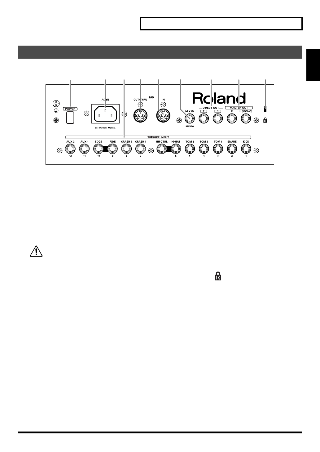
Rear Panel
fig.rear_50
12
1.
POWER Switch
This switch turns the power on/off.
* If you need to turn off the power completely, first turn off the
POWER switch, then unplug the power cord from the power
outlet. Refer to
2.
AC Inlet
Connect the included AC power cable to this inlet.
* For details on the power consumption, refer to p. 99.
3.
TRIGGER INPUT Jacks
Here is where you plug in pads, kick triggers, or acoustic
triggers. With dual trigger pads (PD-125/105/85/8),
cymbals (CY series), and a hi-hat (VH-11/12), use a stereo
(TRS) cable (p. 17).
Power Supply
The unit should be connected to a power source
only of the type marked on the bottom of the
unit.
(p. 5).
Panel Descriptions
83 4 5 7 96
6.
MIX IN Jack
Used for connecting any external audio source (p. 18).
This audio signal will be output from the MASTER OUT
jacks and/or PHONES jack. Other signal routing
possibilities (p. 76).
7.
DIRECT OUT Jacks
Individual outputs have a variety of uses. The TD-12
offers many options. See the SETUP screen (p. 76).
8.
MASTER OUT Jacks
For connecting to your amp/audio system. For monaural
output, use the MASTER OUT L (MONO) jack.
9.
Security Slot ( )
For retail store use.
http://www.kensington.com/
Overview
4.
MIDI OUT/THRU Connector
For using the TD-12/pads to play sounds in an external
MIDI sound module, or recording/saving data to an
external MIDI sequencer (pp. 72–75).
5.
MIDI IN Connector
To connect an external MIDI source (sequencer, pad
controller, keyboard, computer, etc.) to play the TD-12’s
sounds, or to load data (pp. 72–75).
15
Page 16
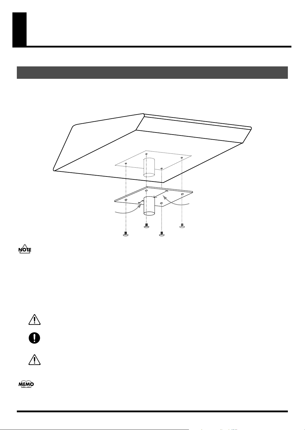
Setting Up the Kit
Mounting the TD-12 on the Stand
1.
Attach the stand holder (included with the optional drum stand) to the TD-12.
Using the screws attached to the bottom panel, attach the holder so the unit is oriented as shown in the diagram.
* ONLY use the 12 mm screws (M5 x 12) provided with the TD-12. Other screws may damage the unit.
fig.StandHolder.e
Wide
Narrow
928, 929
• When turning the unit upside-down, get a bunch of newspapers or magazines, and place them under the
four corners or at both ends to prevent damage to the buttons and controls. Also, you should try to orient
the unit so no buttons or controls get damaged.
• When turning the unit upside-down, handle with care to avoid dropping it, or allowing it to fall or tip over.
2.
Attach the TD-12 and stand holder to the drum stand (such as the optional MDS-12).
See the owner’s manual for the stand for details on assembling the drum stand and attaching the TD-12.
005
006
101c
This unit should be used only with a stand that is recommended by Roland.
When using the unit with a stand recommended by Roland, the rack or stand must be carefully placed so it is level
and sure to remain stable. If not using a rack or stand, you still need to make sure that any location you choose for
placing the unit provides a level surface that will properly support the unit, and keep it from wobbling.
This TD-12 for use only with Roland stand MDS series. Use with other stands is capable of resulting in instability
causing possible injury.
The optional APC-33 All Purpose Clamp can be attached to a pipe of 10.5–28.6 mm radius in case you
want to mount the TD-12 on a cymbal stand or other such stand.
16
Page 17
Connecting the Pads and Pedals
Setting Up the Kit
Using the provided cables, connect the pads, cymbals, hi-hat, and kick trigger pad.
* When mounting a TD-12 on an MDS-12 drum stand, use the built-in connection cables.
Set Up Example
fig.Kit.e
TD-12 Rear Panel
7 / CRASH 1 (BOW/EDGE)
CY-12R/CCY-12R/C
6 / HI-HAT (TRIGGER OUT)
HH CTRL (CTRL OUT)
VH-11VH-11
TD-12
3 / TOM 1
PD-85
9 / RIDE (BOW/BELL)
10 / EDGE (BOW/EDGE)
4 / TOM 2
PD-85
CY-12R/CCY-12R/C
Overview
PD-105
The HI-HAT and RIDE cymbal use two cables each. See p. 20 and p. 52.
2 / SNARE
KD-85
1 / KICK
5 / TOM 3
PD-85
17
Page 18

Setting Up the Kit
Connecting Headphones, Audio Equipment, Amps, or Other Gear
fig.Connect.e
Speakers with built-in amp etc.
L
CD/MD player etc.
TD-12 Rear Panel
Stereo phone type
R
Stereo set etc.
Phone type
Stereo phone type
TD-12 Front Panel
1.
Turn off the power of all devices before you
make connections.
921
* To prevent malfunction and/or damage to speakers or other
devices, always turn down the volume, and turn off the power
on all devices before making any connections.
2.
Connect the MASTER OUT L (MONO) and R
jacks on the rear panel to your audio system or
amp. Headphones should ONLY be connected
to the PHONES jack.
3.
Connect the supplied power cord to the AC
inlet.
4.
Plug the power cord plug into a power outlet.
18
The TD-12’s MIX IN jack allows you to play along with a
CD or other audio sources.
• To adjust the volume of the device connected to the MIX
IN jack, turn the [MIX IN] knob on the TD-12’s top panel.
• The sound input from the MIX IN jack can be output
from the MASTER OUT, PHONES, or DIRECT OUT 1/2
jacks (p. 76).
926a
* When connection cables with resistors are used, the volume
level of equipment connected to the MIX IN jack may be low. If
this happens, use connection cables that do not contain
resistors, such as those from the Roland PCS series.
Page 19
Setting Up the Kit
Turning On/Off the Power
941
* Once the connections have been completed (p. 17, p. 18), turn
on power to your various devices in the order specified. By
turning on devices in the wrong order, you risk causing
malfunction and/or damage to speakers and other devices.
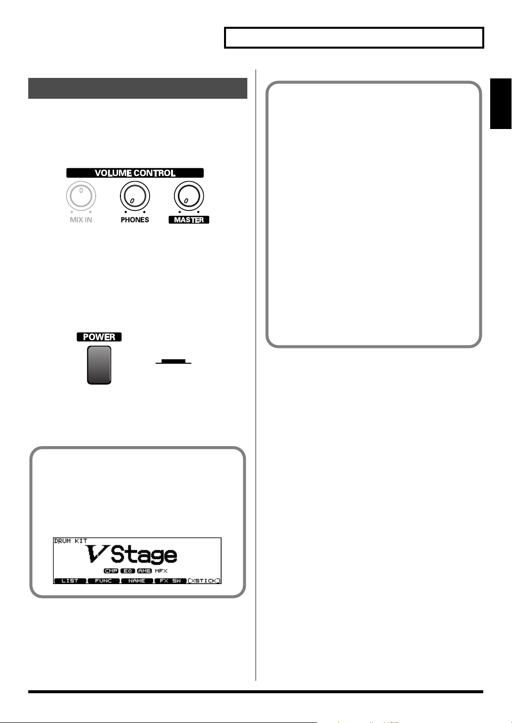
fig.VolMin
1.
Turn the [MASTER] and [PHONES] completely
to the left to lower the volume to “0.”
2.
Turn down the volume control on the
connected amp or audio system.
3.
Push the [POWER] switch on the TD-12’s rear
panel to turn on the power.
fig.PowerOn.e
Lower Position
ON
942
* This unit is equipped with a protection circuit. A brief interval
(a few seconds) after power up is required before the unit will
operate normally.
Precautions When Turning on the
Power
After the power is turned on, do NOT hit any pads or
step on the pedals until the drum kit name (following
figure) appears in the display. Doing so can cause
triggering problems.
fig.00-006
No Sound When Hitting the Pads or Using the
Pedals?
Check the following points.
When Using an Amp or Audio System
• Is the amp or audio system connected to the TD-12’s
MASTER OUT jacks?
• Is the input of the amp or audio system properly
connected?
• Is there a problem with any connection cables?
• Is the volume turned down in the [GROUP
FADERS] sliders?
• Is [MASTER] turned completely to the left?
• Have the input select settings of your audio system
or amp been made correctly?
• Is the amp or audio system volume setting correct?
When Using Headphones
• Are the headphones connected to the PHONES jack?
• Is [PHONES] turned completely to the left?
Turning Off the Power
1.
Completely turn down the volume of the TD-12
and any connected external devices.
2.
Turn off the power to all external devices.
3.
Push the [POWER] switch on the TD-12’s rear
panel to turn off the power.
945
* If you need to turn off the power completely, first turn off the
POWER switch, then unplug the power cord from the power
outlet. Refer to
Power Supply
(p. 5).
Overview
4.
Turn on the power to the connected amp or
audio system.
5.
While hitting a pad, gradually turn [MASTER]
(or [PHONES]) to the right to adjust the volume
level.
19
Page 20
Setting Up the Kit
Connecting the Hi-Hat (VH-11) and Setting the “VH Offset”
When using the VH-12, the “VH Offset” needs to be set up.
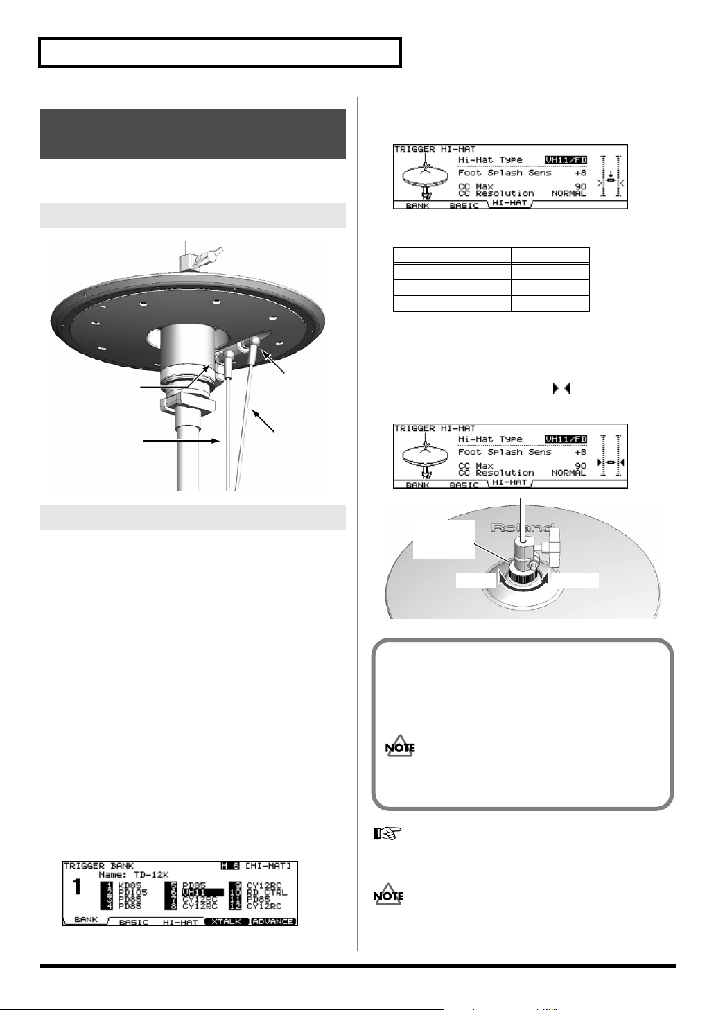
7.
Press [F3 (HI-HAT)].
The “TRIGGER HI-HAT” screen appears.
fig.05-VH11-Offset2
Connecting the Hi-Hat
fig.VH-Connect.e
CONTROL
OUT jack
to the
TD-12’s
HH CTRL jack
TRIGGER
OUT jack
to the
TD-12’s
TRIGGER INPUT
HI-HAT jack
Adjusting the Offset
1.
Confirm that the VH-11 and TD-12 are
connected properly.
2.
After making the hi-hat settings, release your
foot from the pedal, and while keeping your foot
off the pedal, turn on the power to the TD-12.
* The offset cannot be adjusted correctly if the hi-hat is making
contact with the motion sensor unit when the power is turned on.
3.
Loosen the clutch screw and let the hi-hat rest
naturally on the motion sensor unit.
4.
Press [TRIGGER] - [F1 (BANK)].
[TRIGGER] lights, and the “TRIGGER BANK” screen
appears.
5.
Press [CURSOR] to move the cursor to the
trigger type for TRIGGER INPUT 6.
8.
Confirm the TD-12’s settings.
Parameter Value
Hi-Hat Type VH11/FD
CC Max 90
CC Resolution NORMAL
9.
While reading the meter displayed on the right
side of the TD-12’s screen, adjust the offset
with the VH-11’s VH offset adjustment screw.
Adjust the offset so that a black appears in the
meter.
fig.05-VH11-Offset3
fig.Offset.e
VH Offset
Adjustment
Screw
OPEN CLOSE
VH Offset Adjustment Points
If the closed hi-hat sound is difficult to attain, rotate the
VH offset adjustment screw towards “CLOSE.”
If the open hi-hat sound is difficult to attain, rotate the
screw towards “OPEN.”
If the sound cuts off when you strike the hi-hat
forcefully, rotate the VH Offset adjustment screw
towards “OPEN.”
6.
Use [+/-] or [VALUE] to select “VH11.”
fig.05-VH11-Offset1
20
If you need, make further adjustments to the parameters.
Hi-Hat Settings [F3 (HI-HAT)]
If you do not make VH-11’s setting correctly, it may cause
malfunction. For details, refer to the VH-11 owner’s
manual.
(p. 46)
Page 21

The band has a width of 7 mm.
Use this for adjusting the head tension.
7 mm
Setting Up the Kit
Adjusting Mesh Head Tension
Heads MUST BE TUNED BEFORE PLAYING.
When adjusting, use a tuning key.
Like with an acoustic drum, accurate and equal head tension
is needed for correct triggering response.
On the PD-105/85, adjusting the head tension affects only
the head response, and not the pitch of the sound, as it
would on an acoustic drum.
Adjusting the PD-105 Head Tension
1.
Loosen the tuning bolts until a slight gap is
produced.
2.
Tighten all tuning bolts by fingers, as tightly as
you can.
fig.PD105-Nut.e
Tuning bolt
Washer
3.
Using the tuning key, turn the tuning bolts two
full revolutions each, thus tightening them.
Tighten each tuning bolt one by one, observing the
numerical order shown in the figure.
fig.PD105-BoltOrder
Slight gap
Hoop
Adjusting the PD-85 Head Tension
1.
Use the included tuning key to tighten the
tuning bolts.
Tighten the bolts until there is a space of approximately 7
mm between the frame and the hoop.
* The setup includes a lock bushing (to prevent loosening), so the
bolt should be tightened fairly securely.
fig.PD85-Adjust.e
Hoop
7mm
Frame
A black, 7 mm strip is printed at the edge of this page.
Use this as a reference when making the adjustment.
Tighten each tuning bolt one by one, observing the
numerical order shown in the diagram. Do not firmly
tighten a single tuning bolt by itself. Doing so will make
it impossible to tension the head evenly, and will cause
malfunctions.
fig.PD85-Bolt
3
1
5
Overview
13
6
4
2
HEAD MADE BY REMO U.S.A.
4
2
2.
5
Fine-tune the adjustment while continuing to
check the pad feel and response.
21
Page 22

Playing Methods
Pad (PD-105/PD-85)
fig.Play-Head.e
Head Shot
Hit only the head of the pad.
With certain snare sounds,
playing position will change
the nuance of the sound.
* Select an instrument from the Drum Instrument List (p. 88)
with “*P” appended to the name.
fig.Play-Rim.e
Rim Shot
Strike the head and the rim of
the pad simultaneously.
fig.Play-Cross.e
Cross Stick
Only strike the rim of the pad.
Depending on the instrument
assigned to the rim you can
play rim shots and/or cross
stick sounds.
* Select an instrument from the Drum Instrument List (p. 88)
with “*X” appended to the name.
* Enable cross sticks with the drum kit (press [KIT] - [F5
(XSTICK)]; p. 32).
* To play the cross stick, be sure that you only strike the rim of
the pad. Placing your hand on the head of the pad might
prevent the cross stick sound from being played properly.
Head
Head
Rim
Rim
Rim
fig.Play-Shallow.e
Shallow Rim Shot
Simultaneously strike the head near
the rim and the rim itself.
* Select an instrument from the
Drum Instrument List (p. 88)
with “*P” appended to the name.
Head
Rim
Brush Sweeps
You can express a sweep sound using brushes (brush sweeps).
* Select an instrument from the Drum Instrument List (p. 88)
with “*BRUSH” appended to the name.
* Enable brush performances with the drum kit (press [KIT] - [F2
(FUNC)] - [F3 (BRUSH)], Brush Switch = ON; p. 32).
* Brush sweeps can be used only on SNARE.
When using brushes, be sure to use nylon brushes. Using
metal brushes will not only scratch the head, but can also
be hazardous, since the tip of the brush may catch in the
mesh of the net.
Cymbal (CY-12R/C)
Bow Shot
This is the most common playing method, playing the middle
area of the cymbal. It corresponds to the sound of the “head-
side” of the connected trigger input.
fig.Play-CYBow
Change the Nuance of the Rim Shot
With certain snare and tom sounds, slight changes in the way
you play rim shots changes the nuance.
fig.Play-Rim.e
Normal Rim Shot
(Open Rim Shot)
Strike the head and rim
simultaneously.
Head
Rim
22
Edge Shot
This playing method involves striking the edge with the
shoulder of the stick. When played as shown in the figure, the
“rim-side” sound of the connected input is triggered.
fig.Play-CYEdge.e
Edge sensor
Page 23

Bell Shot
This playing method involves striking the bell. When played
as shown in the figure, the “rim-side” sound of the connected
input is triggered.
fig.Play-Bell
Playing Methods
Hi-Hat (VH-11/VH-12)
Open/Closed
The hi-hat tone changes smoothly and continuously from
open to closed in response to how far the pedal is pressed.
You can also play the foot closed sound (playing the hi-hat
with the pedal completely pressed down) and foot splash
sound (playing the hi-hat with the pedal fully pressed and
then instantly opening it).
Overview
* Strike the bell somewhat strongly with the shoulder of the stick.
Choke Play
Choking (pinching) the cymbal’s edge with the hand
immediately after hitting the cymbal makes the sound stop.
Choke the location of the edge sensor shown in the figure. If
you choke an area where there is no sensor, the sound does
not stop.
fig.Play-Choke.e
Roland logo
Edge sensor
Positional Sensing
fig.Play-CYPosi
Pressure (VH-12 Only)
When you strike the hi-hat while pressing on the pedal with
the hi-hat closed, you can then change the closed tone in
response to the pressure you place on the pedal.
Bow Shot
This playing method involves striking the middle area of the
top hi-hat. It corresponds to the sound of the “head-side” of
the connected trigger input.
fig.Play-VHBow
Edge Shot
This playing method involves striking the edge of the top hihat with the shoulder of the stick. When played as shown in
the figure, the “rim-side” sound of the connected trigger input
is triggered.
fig.Play-VHEdge.e
With certain ride sounds, playing position will change the
nuance of the sound.
* Only TRIGGER INPUT 9 RIDE corresponds to the positional
sensing.
* Select an instrument from the Drum Instrument List (p. 88)
with “*P” appended to the name.
Edge Sensor
* Do not strike the bottom hi-hat or the underside of the top hi-
hat.
23
Page 24
Button Operation and Displays
Operations common to all aspects TD-12 operations.
Changing Data Values
Saving Your Settings
Every time you change a value during the editing process, it’s
automatically stored in the TD-12’s memory. There’s no
“write/save” process.
fig.00-004_40
Buttons, Sliders, Dial and Knobs
References for top panel buttons, sliders, dial and knobs will
be printed in square brackets [ ]; e.g., [SETUP].
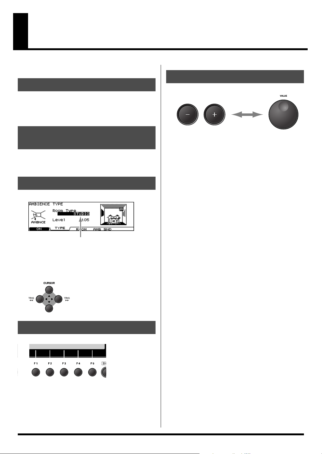
Cursor
fig.00-001e_70
Cursor
Cursor refers to the highlighted characters indicating an on-
screen parameter that can be set. When there is more than one
possibility within the screen, use the [CURSOR] buttons to
move it.
fig.00-002_50
[+] and [-] (referred to in this manual as [+/-]) and the
[VALUE] dial are both used to change the values of settings.
Both methods have advantages.
[+/-]
• Each time [+] is pressed, the value increases. Each time [-]
is pressed, the value decreases. This is convenient for fine
adjustments.
• When making an on/off setting, [+] will turn the setting
on and [-] will turn it off.
• If you hold down [+] and press [-], the value will increase
rapidly. If you hold down [-] and press [+], the value will
decrease rapidly.
[VALUE] dial
The dial allows you to make major changes to the value
quickly. If you hold down [SHIFT] and turn [VALUE], the
value will change even more rapidly.
Function Buttons ([F1]–[F5])
fig.00-003_50
The [F1]–[F5] buttons are called “function buttons.” The
bottom part of the display will show the names of the
functions available for [F1]–[F5]. For example, if this owner’s
manual makes reference to [INST] - [F2 (EDIT)], press [INST],
and then press [F2] (in this case, “EDIT” is displayed above
[F2]).
24
Page 25
Choosing Pads from the TD12’s Top Panel
fig.00-007_70
The [CURSOR] (TRIG) buttons can be used to select the pad/
trigger input to be edited without needing to hit a pad.
• Holding down [SHIFT] and pressing [CURSOR (left)]:
The next lower-numbered trigger will be selected.
• Holding down [SHIFT] and pressing [CURSOR (right)]:
The next higher-numbered trigger will be selected.
Button Operation and Displays
Changing the Tone Through the Strike
Position and Rim Shot Nuance and
Confirming the Closed Hi-Hat Tone
You can change the tone by changing the strike position and
rim shot nuance and confirm the closed hi-hat tone by holding
down [SHIFT] and pressing [PREVIEW].
Corresponding Inputs and Tone Changes That Can
Be Checked
INPUT Effect
2 SNARE Head Tone Change from Strike Position
Rim Rim Shot Nuance
3 TOM 1–
5 TOM 3
6 HI-HAT Head Closed Hi-Hat Tone
9 RIDE Head
11 AUX 1,
12 AUX 2
Rim Rim Shot Nuance
Rim Closed Hi-Hat Tone
Tone Change from Strike Position
(Bow)
Rim Rim Shot Nuance
How to Play Patterns
fig.06-003_70
Overview
If you are using a rim-capable pad, [RIM] selects whether the
settings being made are for the head or the rim. When [RIM] is
lit, it indicates that the rim is selected.
Holding down [SHIFT] as you press [RIM] locks the pad
(trigger) being set, so that the pad being set is not switched
even if another pad is touched. [RIM] flashes when a pad is
locked. To cancel the lock, hold down [SHIFT] and press
[RIM] once again.
* You can switch between the head and rim of the pad being set,
even when [RIM] is flashing, by holding down [SHIFT] and
pressing [CURSOR (left/right)].
By using these functions together with [PREVIEW], you can
edit the TD-12 only.
Convenient [PREVIEW] Functions
Checking the Tone While Changing the
Velocity
You can toggle between three velocity (volume) levels by
holding down [KIT] and pressing [PREVIEW].
Set the three velocity levels by pressing [SETUP] - F3
(CONTROL)] - [F2 (PREVIEW)] (p. 77).
Pressing [PATTERN]. The basic screen for the sequencer
appears.
Press [+/-] or turn [VALUE] in this screen to choose a pattern.
Or press [F1 (LIST)] to choose from the pattern list.
fig.06-001
Press [PLAY] to start playback of the pattern.
Press [STOP] to stop playback.
Press [STOP] again to return to the top of the pattern.
How to Turn the Metronome (Click) On/Off
Hold down [SHIFT] and press [TEMPO] to turn ON and OFF.
* The [TEMPO] indicator can also be used as a visual
metronome (p. 62).
25
Page 26
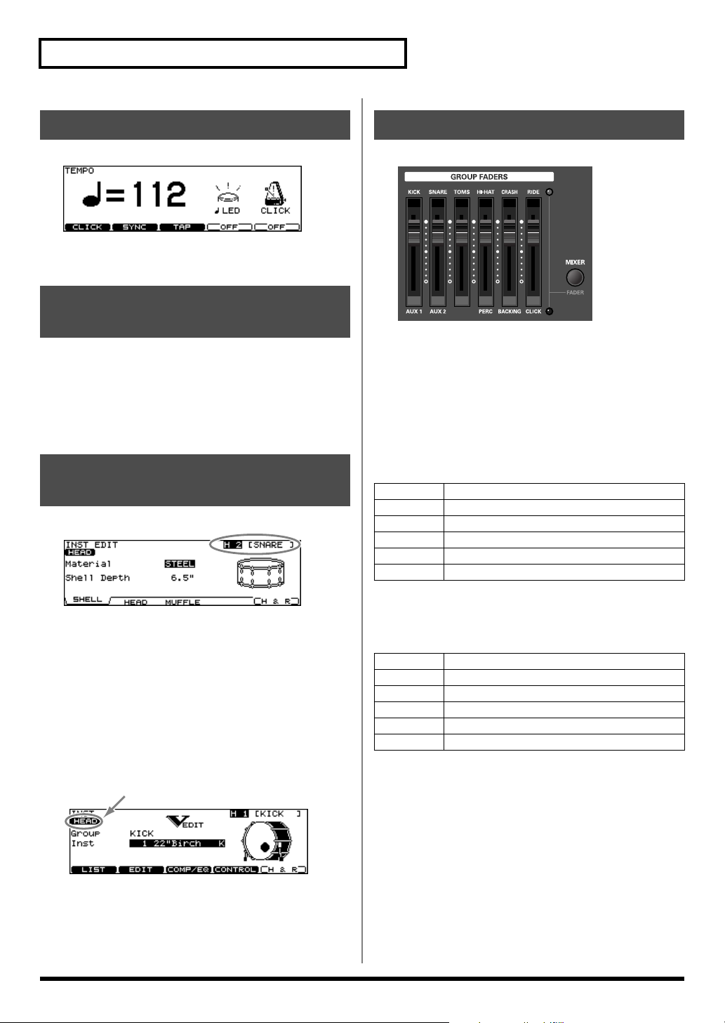
Button Operation and Displays
How to Adjust the Tempo
fig.06-Tempo1_70
To adjust the tempo of the sequencer and click, use [+/-] or
[VALUE] in the screen displayed by pressing [TEMPO].
Adjusting the Display Contrast
Display contrast can be influenced by location and lighting.
When needed, adjust the display contrast by:
holding down [KIT] and turning [VALUE]
* You can also adjust it in the screen displayed by pressing
[SETUP] - [F3 (CONTROL)] - [F3 (LCD)] (p. 77).
.
About the Display in the Upper Right of the Screen
fig.00-005_70
Group Faders
fig.00-009
Use [GROUP FADERS] sliders to adjust the volume.
If you press the [FADER] button, the function of the faders
will change as is explained in the chart below. An LED will
light up at the upper and lower right of the faders to indicate
which set of sounds is active.
• When upper indicator is lit, you can adjust the volume of
following trigger inputs.
KICK
SNARE
TOMS
HI-HAT
CRASH
RIDE
1 (KICK)
2 (SNARE)
3 (TOM 1), 4 (TOM 2), 5 (TOM 3)
6 (HI-HAT)
7 (CRASH 1), 8 (CRASH 2)
9 (RIDE), 10 (EDGE)
Many edit screens require you to hit a pad or press the
[PREVIEW] button to access the parameters you want. The
upper right of the display will show the number and trigger
input jack name of the corresponding pad. The first character
(“H” or “R”) stands for Head or Rim. ([RIM] lights up when
played.)
You can use the CURSOR (TRIG) buttons and [PREVIEW] to
get the same results. In cases where settings for the head and
rim can be edited separately, the following characters will also
be displayed.
fig.00-006_70
26
• When lower indicator is lit, you can adjust the volume of
following trigger inputs and sequencer parts.
AUX 1
AUX 2
(none)
PERC
BACKING
CLICK
Example: Adjusting the Snare Volume
1.
Press [FADER] so the upper indicator is lit.
2.
Move the [GROUP FADERS] [SNARE] slider.
The slider position shows the current snare volume.
* After switching with [FADER], the values for the [GROUP
FADERS] sliders may not reflect the actual volume of the
sound assigned to that fader. So after switching, be sure to
move the faders a bit before making your setting.
* This will NOT affect the independent volume balance for each
kit in: Mixer Settings (p. 39).
11 (AUX 1)
12 (AUX 2)
–
Percussion part (p. 57)
Backing part (p. 56)
Metronome click (p. 62)
Page 27
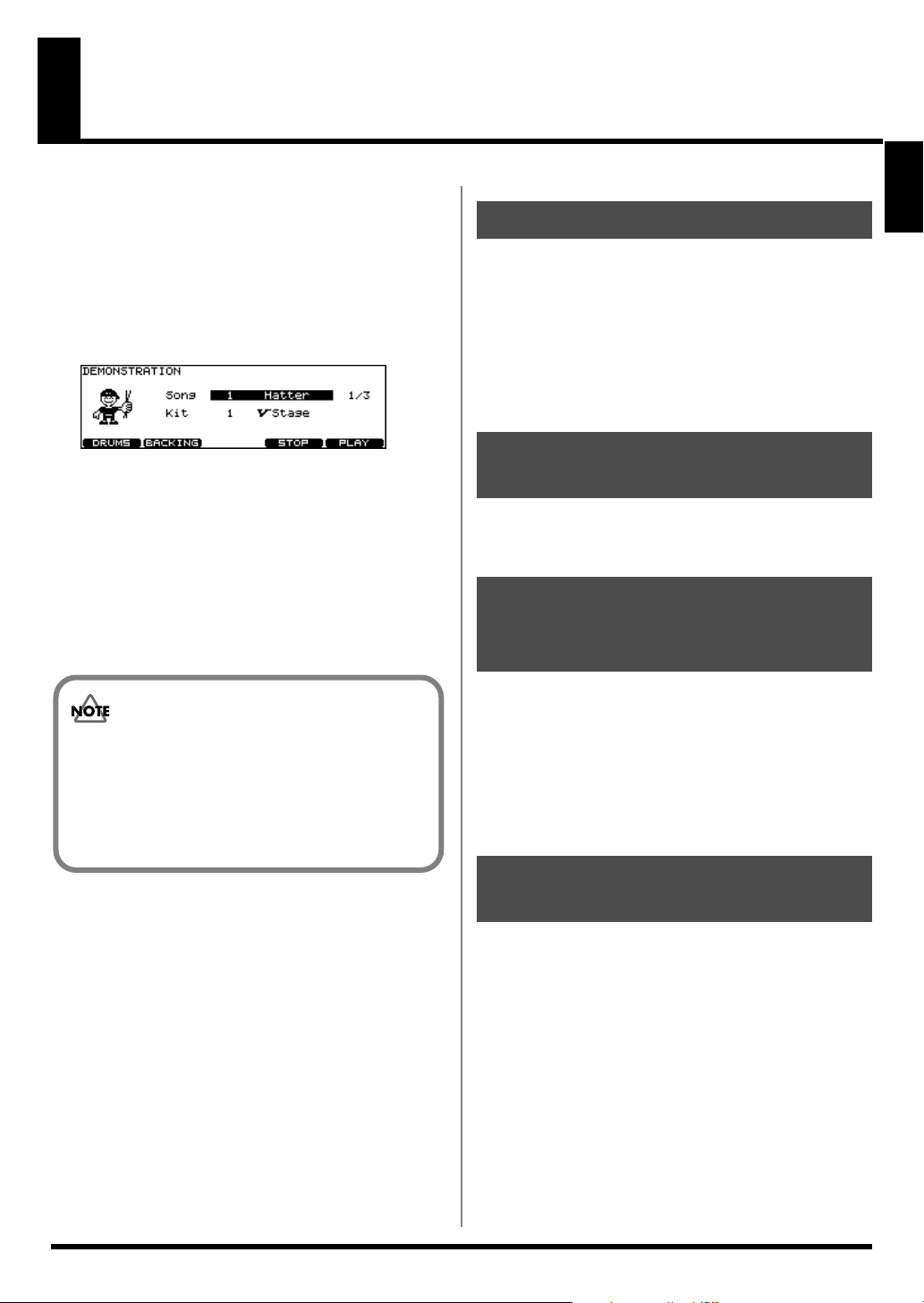
Listening to the Demo Song
The internal demo song features the TD-12’s expressive
capabilities and top quality sounds. The drums on this song
were recorded from the TD-12 system to a sequencer in real
time.
1.
Hold down [SHIFT] and press [CHAIN].
The “DEMONSTRATION” screen appears.
fig.Demo_70
2.
Use [+/-] or [VALUE] to select a song.
3.
Press [F5 (PLAY)].
Playback begins; the three demo songs are played back
repeatedly.
4.
Press [F4 (STOP)] to stop the demo song.
5.
Press [EXIT] or [KIT] to return to the “DRUM
KIT” screen.
Caution Concerning Volume
When playing back the demo song, turn [MASTER] and
[PHONES] to the left (counterclockwise) to bring the
volume level down. The sound levels (volume) of the
instruments may be louder when the demo song is
played back.
Changing the Drum Kits
You can change the drum kit used to play the demo songs.
1.
Press [CURSOR (down)] to move the cursor to
“Kit.”
2.
Use [+/-] or [VALUE] to select a drum kit.
* Demo songs are normally played using factory preset drum
kits.
Changing the Volume Balance
You can change the volume balance with [GROUP FADERS]
(p. 26).
Muting the Performance of the Backing Instruments and Drums
As drums are used to play the demo songs, you can mute
drum parts.
[F1 (DRUMS)]
You can MUTE the entire drum track.
[F2 (BACKING)]
You can MUTE all the backing instruments.
Overview
Demo Song
Hatter Copyright © 2005, Roland US
Brisa Copyright © 2005, Roland US
Cluster Hang Copyright © 2004, Roland US
981a
* All rights reserved. Unauthorized use of this material for
purposes other than private, personal enjoyment is a violation
of applicable laws.
982
* No data for the music that is played will be output from MIDI
OUT.
Turning the Metronome (Click) On/Off
You can have the metronome click sound in time with the
demo songs.
1.
Start by setting the click instrument and count
(p. 63).
2.
Hold down [SHIFT] and press [CHAIN].
The “DEMONSTRATION” screen appears.
3.
Hold down [SHIFT] and press [TEMPO] to turn
the metronome click (p. 62) on/off.
27
Page 28
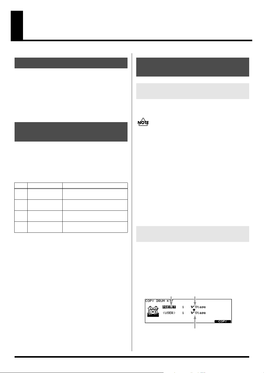
Useful Functions to Know
About the Preset Drum Kits
The TD-12 is shipped from the factory with 50 pre-loaded
drum kits. These drum kits are referred to as
Kits
.
The features of each preset drum kit, pad pattern function
settings, and other information is listed in the
Kit List
(p. 84). Look through this list to find the kit you want
to use.
Preset Drum
Preset Drum
Playing Patterns to Check Drum Kit Tones
The preset patterns offer a convenient way to check the drum
kit sounds.
By selecting instruments and then playing back patterns with
these instruments, you can confirm the sounds of instrument
combinations; for example, kick and snare or snare and tom.
Name Use
No.
DrumPreview1 To check the kick, snare, and hi-
1
2 DrumPreview2 To check the kick, snare, and ride
3 DrumFill 1 To check the tom and crash cym-
4 DrumFill 2 To check the tom and crash cym-
* You can use the [GROUP FADERS] to change the volume
balance and mute any unneeded instrument sounds.
hat sounds
cymbal sounds
bal sounds
bal sounds
Restoring Edited Drum Kits to the Factory Default Settings
Restoring All Settings to the Factory Settings
This restores the TD-12 to the original factory settings
(
Factory Reset
All data and settings stored in the TD-12 are lost in
carrying out this operation. So if necessary, save your
data to an external MIDI device before executing the
factory reset.
(Bulk Dump; [SETUP] - [F1 (MIDI)] -[F5 (BULK)]; p. 75)
1.
Press [SETUP] - [F5 (F RESET)].
[SETUP] lights, and the “FACTORY RESET” screen
appears.
2.
Press [F5 (RESET)].
The confirmation screen appears.
* To cancel, press [F1 (CANCEL)].
3.
Press [F5 (EXECUTE)] to execute Factory
Reset.
When Factory Reset is finished, the “DRUM KIT” screen
appears.
Restoring the Factory Settings to Individual Kits
When resetting individual drum kits whose instrument and/
or effect settings have been changed to the original factory
settings, use the Copy function (p. 70).
).
28
1.
Hold down [SHIFT] and press [SETUP].
[SETUP] lights, and the “COPY” screen appears.
2.
Press [F1 (KIT)].
fig.00-CopyKit_70
A
A:
copy-source type (PRESET or USER)
B:
copy-source
C:
copy-destination
B
C
Page 29
3.
Use [+/-] or [VALUE] to select “PRESET” for the
copy-source type.
4.
Use [CURSOR], [+/-], or [VALUE] to select the
copy-source kit and the copy-destination kit.
5.
Press [F5 (COPY)].
The confirmation screen appears.
* To cancel, press [F1 (CANCEL)].
6.
Press [F5 (EXECUTE)] to carry out.
Useful Functions to Know
Striking a Pad to Switch the
Drum Kits
Overview
(Pad Switch Function)
You can switch drum kits and patterns by striking the pads
connected to AUX 1 and AUX 2 (press [SETUP] - [F3
(CONTROL)] - [F1 (PAD SW)]; p. 76).
Playing Back Patterns by Striking the Pads (Pad Pattern Function)
You can set up a pattern beforehand and then strike a pad to
start the performance of the pattern (press [INST] - [F4
(CONTROL)] - [F1 (PATTERN)]; p. 37).
Some factory set drum kits (Preset drum kits) have this
function set.
* When playing back patterns with recorded drum kit
performances or demo songs, the patterns assigned to the pads
are not played back, even if the Pad Pattern function is enabled
for the selected drum kit.
* Performances using the Pad Pattern function cannot be
recorded to sequencers.
* With Pad Pattern, performance of the pattern starts only when
the pad is struck with sufficient force.
If the pad is struck weakly, only the instrument sound assigned
to the pad is played; the pattern is not played back.
Stopping Playback of the Pattern Being Played
Press [STOP].
Disabling the Pad Pattern Function
Enabling Cross Sticks
1.
Press [KIT].
2.
Press [F5 (XSTICK)].
The cross-stick sound is alternately switched on and off
each time you press this.
* Select an instrument from the Drum Instrument List (p. 88)
with “*X” appended to the name.
Playing Along with Patterns
Choosing a Pattern
1.
Press [PATTERN].
[PATTERN] lights, and the “PATTERN” screen appears.
2.
Use [+/-] or [VALUE] to select the pattern.
3.
Press [PLAY].
[PLAY] lights, and playback of the pattern begins.
Muting a Specific Part
1.
Press [PATTERN] - [F2 (PART)] - [F5 (MUTE)].
The “PART MUTE” screen appears.
2.
Press [F1]–[F5] to turn each part muted or
played.
You can switch off the Pad Pattern function for the entire kit,
without having to individually change the settings for each
pad.
Set PadPtn Master Sw (press [KIT] - [F2 (FUNC)] - [F4 (PAD
PTN)]; p. 32) to “ALL PADS OFF.”
29
Page 30
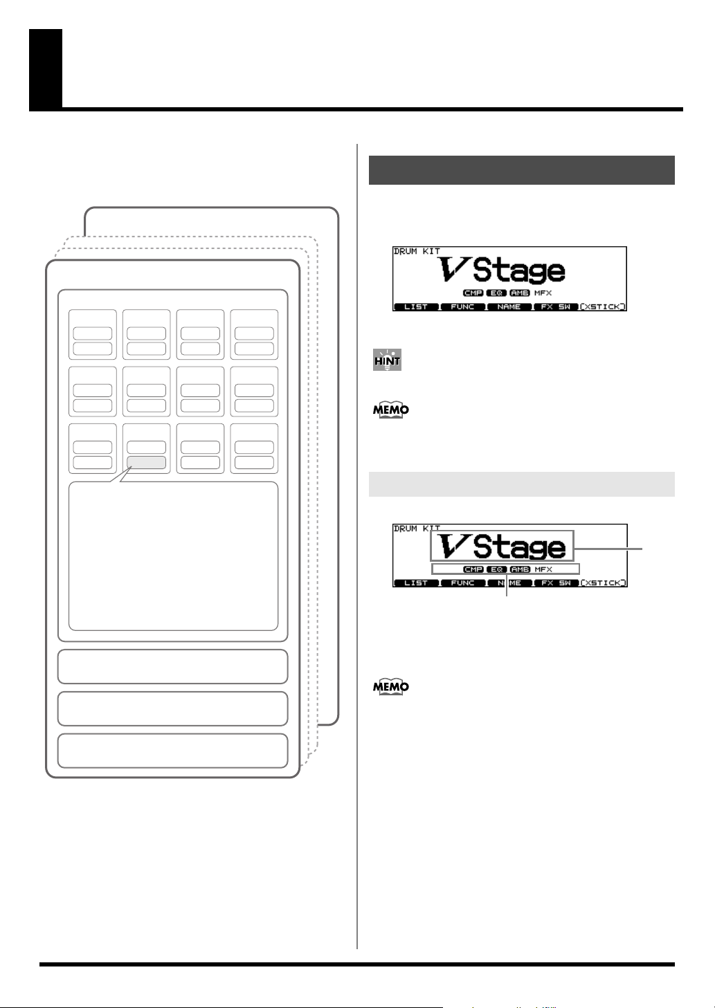
Chapter 1. Drum Kit Settings [KIT]
A “
drum kit
the sounds played with each pad, the hi-hat used, effect
settings, and so on.
fig.01-KitParam.e
Drum Kit 1
” refers to a configuration of settings that include
Drum Kit 50
Pad settings
KICK
Head 1
Rim 1
SNARE
Head 2
Rim 2
TOM1
Head 3
Rim 3
TOM2
Head 4
Rim 4
Choosing a Drum Kit
1.
Press [KIT].
[KIT] lights, and the “DRUM KIT” screen appears.
fig.01-001*_70
2.
Use [+/-] or [VALUE] to select drum kits.
TOM3
Head 5
Rim 5
RIDE
Head 9
Rim 9
Instrument settings
Instrument, V-EDIT/EDIT
Mixer settings
Volume, Pan, Minimum Volume
Effects settings
Compressor, Equalizer settings
Ambience/Multi-Effects Send Level
Various Function Settings
Pad Pattern setttings
Pitch Control function settings, MIDI settings
Ambience settings
ON/OFF, Room Type, Wall Type, etc.
Multi-Effects settings
ON/OFF, Type, effect level, etc.
Settings Affecting the Entire Drum Kit
Volume, Drum Kit Name, MIDI settings, etc.
HI-HAT
Head 6
Rim 6
EDGE
Head 10
Rim 10
CRASH1
Head 7
Rim 7
AUX1
Head 11
Rim 11
CRASH2
Head 8
Rim 8
AUX2
Head 12
Rim 12
Pads can be programmed to make selections (p. 76).
The selected or current kit number is indicated at all
times in the LED display at the left of the LCD display.
About the “DRUM KIT” Screen
fig.01-001_70
B
A:
Drum Kit Name
B:
Overall Kit Effects On/Off status (p. 40)
Pressing [KIT] always takes you back to the “DRUM KIT”
screen, from any Edit mode in the TD-12.
A
30
Page 31

Chapter 1. Drum Kit Settings [KIT]
Selecting a Drum Kit from the List [F1 (LIST)]
You can select a drum kit by accessing the list of available kits.
fig.01-002_70
1.
Press [KIT] - [F1 (LIST)].
The “DRUM KIT LIST” screen appears.
2.
Use [VALUE], [+/-], or [CURSOR] to select a
drum kit.
Function Buttons
[F1 (< PAGE)]
The previous page of the list appears.
[F2 (PAGE >)]
The next page of the list appears.
3.
Press [EXIT] (or just press [KIT]) to return to the
“DRUM KIT” screen.
Assigning a Tempo for Each Kit [F2 (TEMPO)]
Each kit can have an individual tempo setting.
When you select a kit of which Kit Tempo is set to “ON,” the
tempo you define here will be set automatically.
fig.01-004_70
Parameter Value Description
Kit Tempo OFF, ON
Tempo 20–260 defined tempo
When you select a kit of which Kit Tempo is set to “ON,”
the current tempo appears in the upper right of the
display.
fig.01-004a_70
OFF:
tempo is not defined
ON:
tempo is defined
[KIT]
Chapter 1
Kit Parameters [F2 (FUNC)]
1.
Press [KIT] - [F2 (FUNC)].
2.
Press [F1]–[F4] and [CURSOR (up/down)] to
select the parameter.
3.
Use [+/-] or [VALUE] to make settings.
Adjusting the Volume [F1 (VOLUME)]
fig.01-003_70
Parameter Value Description
Kit Volume 0–127 Volume of the entire drum
kit
Pedal HH Volume 0–127 Volume of the hi-hat’s foot
closed sound
XStick Volume 0–127 Volume of cross stick sound
Confirming the Tempo Before
Giving the Count
First, set up the drum kits for each song to be performed
with the tempos set in advance.
Setting the Tempo indicator (p. 62) to “ON” then allows
you to confirm the song tempo each time you switch the
drum kit. You can also check the tempo with the click
sound.
31
Page 32

Chapter 1. Drum Kit Settings [KIT]
Playing Brushes [F3 (BRUSH)]
In each kit, you can choose whether sticks or brushes will be
used.
fig.01-005_70
Parameter
Brush
Switch
* Select an instrument from the Drum Instrument List (p. 88)
with “*BRUSH” appended to the name.
When Brush Switch is set to “ON,” the brush icon
appears in the “DRUM KIT” screen.
fig.01-005_70
Value Description
OFF:
OFF, ON
for using sticks
ON:
for using brushes
1.
Press [KIT] - [F3 (NAME)].
The “DRUM KIT NAME” screen appears.
2.
Press [CURSOR (left/right)] to move the cursor
to the character to be changed.
3.
Use [VALUE], [+/-], or [CURSOR (up/down)] to
change the character.
Function Buttons
[F1 (INSERT)]:
[F2 (DELETE)]:
[F3 (SPACE)]:
[F4 (CHAR)]:
A blank space is inserted at the cursor
position, and characters after this point are
moved to the right one space.
Character at the cursor position is deleted,
and characters after this point are moved to
the left one space.
Character at the cursor position is replaced
by a blank space.
Type of character at the cursor position
changes between uppercase/lowercase
alphabet, or numbers and symbols.
Effects On and Off Switches [F4 (FX SW)]
Disabling the Pad Pattern Function [F4 (PAD PTN)]
You can switch the Pad Pattern function setting on and off for
each individual kit.
fig.01-PadPtnSw_70
Parameter Value and Description
PadPtn
Master Sw
ALL PADS OFF:
Pad Pattern function not used
ON:
Pad Pattern function used
Naming a Drum Kit [F3 (NAME)]
Each kit’s name can use up to 12 characters.
fig.01-005_70
These switches allow you to turn all individual effects on/off
within each drum kit.
fig.04-001_70
Refer to
Effects On and Off Switches [KIT] - [F4 (FX
SW)]
(p. 40).
Playing Cross Stick [F5 (XSTICK)]
In each kit, you can choose to use/not use cross stick by
pressing [F5 (XSTICK)] in the “DRUM KIT” screen.
You can also switch this with the pads (p. 76).
• Cross-stick sound played
fig.01-007_70
• Cross-stick sound not played
fig.01-008_70
32
* Select an instrument from the Drum Instrument List (p. 88)
with “*X” appended to the name.
Page 33

Chapter 2. Drum Instrument Settings [INST]
Here’s how to select and edit sounds, such as the snare drum
and kick drum.
Choosing a Pad to Edit
There are two basic ways to select the sound you want to edit.
Choose by Hitting a Pad
1.
Press [INST].
[INST] lights, and the “INST” screen appears.
fig.02-001_70
2.
Strike a pad.
The settings screen for the struck pad appears.
To select a pad’s rim, strike the rim.
Lock the Pad You are Editing (TRIG LOCK) [SHIFT] + [RIM]
When editing instruments, you can prevent the screen from
being switched inadvertently even if you hit another pad.
1.
Select the pad to be locked.
The settings screen for the pad appears.
2.
Hold down [SHIFT] and press [RIM] to make it
flash.
The pad is locked and other pads cannot be selected.
3.
To release the lock, hold down [SHIFT] and
press [RIM] to make it stop flashing.
* You can change the pad to be locked by using buttons even if
the [RIM] is flashing.
Assign an Instrument to a Pad
[INST]
Chapter 2
Choose with the Buttons
1.
Press [INST].
[INST] lights, and the “INST” screen appears.
2.
Hold down [SHIFT] and press [CURSOR (left/
right)] to select the trigger input number.
The trigger input number is indicated in the upper part of
the screen.
3.
Press [RIM] to select the head or rim.
Head: [RIM] is unlit.
Rim: [RIM] is lit.
fig.02-002_70
When MIDI Note Number (p. 38) corresponding to a pad
is received, the pad is selected and shown in the screen.
All the TD-12 sounds are referred to as instruments (
fig.02-001_70
1.
Press [INST].
[INST] lights, and the “INST” screen appears.
“Group”:
“Inst”:
2.
Strike a pad.
The settings screen for the struck pad appears.
3.
Press [CURSOR (up/down)] to move the cursor
Type of instrument (Inst Group)
Name of instrument (Inst Name)
to “Group” or “Inst.”
4.
Use [+/-] or [VALUE] to select the Inst group/
instrument.
5.
Press [EXIT] to return to the “DRUM KIT”
screen.
Pressing [F5 (H & R)], you can choose to set the head and
rim simultaneously or individually. When you select the
head and rim simultaneously, the rim’s instrument
number is one bigger than head.
INST
).
33
Page 34

Chapter 2. Drum Instrument Settings [INST]
Selecting an Instrument from the List [F1 (LIST)]
Here you can select from the list of all available instruments.
fig.02-003_70
1.
Press [INST] - [F1 (LIST)].
The “INST LIST” screen appears.
2.
Strike a pad.
The settings screen for the struck pad appears.
3.
Use [VALUE], [+/-], or [CURSOR] to select the
instrument.
Function Buttons
[F1 (< PAGE)]
The previous page of the list appears.
[F2 (PAGE >)]
The next page of the list appears.
[F3 (< GROUP)], [F4 (GROUP >)]
Selects the Inst Group.
[F5 (H & R)]
Switches to select the head and rim instruments
simultaneously or individually.
4.
Press [EXIT] to return to the “INST” screen.
About the Display at the Lower of the
Instrument Name
fig.02-InstInfo_70
Editing Drum Sounds [F2 (EDIT)]
Editing methods differ according to the type of instrument.
Editing an Acoustic Drum Kit (V-EDIT)
V-EDIT allows you to select a head type, shell depth, muffling,
etc. Please see the charts on next page.
When V-EDIT Can Be Used
V-EDIT is possible in the following instrument groups
“KICK,” “SNARE,” “TOM,” “HI-HAT,” “CRASH,”
“SPLASH,” “CHINA,” or “RIDE.”
The following icon appears to indicate instruments which
are V-EDIT compatible.
fig.02-004_70
Editing Other Instruments
Other instruments only allow “Pitch” and “Decay Time”
adjustment.
Editing Procedure
1.
Press [INST] - [F2 (EDIT)].
The “INST EDIT” screen appears.
2.
Strike a pad.
The settings screen for the struck pad appears.
3.
Use [F1]–[F3] and [CURSOR (up/down)] to
select the parameter.
POSI: Instrument marked with “*P” (p. 91)
You can select the effect on/off with pressing
[F4 (CONTROL)] - [F3 (MIDI)] “Position Ctrl.”
It can be correspond only to some special inputs (p.
44)
INTRVL: Instrument marked with “*I” (p. 91)
XSTK: Instrument marked with “*X” (p. 91)
* These appear only when [F5 (H & R)] is off.
34
4.
Use [+/-] or [VALUE] to adjust the setting.
5.
When finished, press [EXIT] to return to the
“INST” screen.
Page 35

Chapter 2. Drum Instrument Settings [INST]
KICK
fig.02-KICK_70
Parameter Value
[F1 (SHELL)]
Shell Depth NORMAL, DEEP1–2
[F2 (HEAD)]
Head Type CLEAR, COATED, PINSTRIPE
Head Tuning -480–+480
[F3 (MUFFLE)]
Muffling OFF, TAPE1–2, BLANKET, WEIGHT
Snare Buzz OFF, ON
SNARE
fig.02-SNARE_70
TOM
fig.02-TOM_70
Parameter Value
[F1 (SHELL)]
Shell Depth NORMAL, DEEP1–2
[F2 (HEAD)]
Head Type CLEAR, COATED, PINSTRIPE
Head Tuning -480–+480
[F3 (MUFFLE)]
Muffling OFF, TAPE1–2, FELT1–2
Snare Buzz OFF, ON
* PINSTRIPE is a registered trademark of Remo Inc., U.S.A.
HI-HAT
fig.02-HIHAT_70
[INST]
Chapter 2
Parameter Value
[F1 (SHELL)]
Material WOOD, STEEL, BRASS
Shell Depth 1.0”–20.0”
[F2 (HEAD)]
Head Type CLEAR, COATED, PINSTRIPE
Head Tuning -480–+480
[F3 (MUFFLE)]
Muffling OFF, TAPE1–2, DOUGHNUTS1–2
Strainer Adj. OFF, LOOSE, MEDIUM, TIGHT
Parameter Value
[F1 (SIZE)]
Size 1"–40"
[F2 (FIXED)]
Fixed Hi-Hat NORMAL, FIXED1–4
NORMAL:
The gap between the top and bottom hi-hat is
controlled by the pedal.
FIXED:
The gap is fixed.
35
Page 36

Chapter 2. Drum Instrument Settings [INST]
CRASH/SPLASH/CHINA/RIDE
fig.02-CYM_70
Parameter Value
[F1 (SIZE)]
Size 1"–40"
[F2 (SIZZLE)]
Sizzle Type OFF, RIVET
[F3 (SUSTAIN)]
Sustain -31–+31
Other Instruments
fig.02-005_70
For some instruments, raising or lowering the value
beyond a certain point may not produce further change.
• KICK/SNARE/TOM: “Head Tuning”
• CRASH/SPLASH/CHINA/RIDE: “Sustain”
• Other Instruments: “Pitch” and “Decay”
Some instruments have the parameters cannot be edited.
• SNARE: “Material” and “Strainer Adj.”
Using the Compressor and EQ [F3 (COMP/EQ)]
Compressor (COMP)
A compressor adjusts the envelope (changes in the volume
over time) and changes the character of the sound in response
to playing dynamics.
fig.04-003_70
Parameter Value
Pitch -480–+480
Decay Time -31–+31
You can edit the instruments of the head and rim
simultaneously. Pressing [F5 (H & R)], you can choose to
set the head and rim simultaneously or individually.
* When the instruments assigned to the head and rim are not in
the same Inst Group, you only can set the head and rim
individually even if [F5 (H & R)] is set to ON.
Equalizer (EQ)
You can use three-band equalizers (for high, middle, and low
frequency ranges) to adjust the sound.
fig.04-004_70
Refer to
Using the Compressor and EQ [INST] - [F3
(COMP/EQ)]
(p. 40).
36
Page 37

Chapter 2. Drum Instrument Settings [INST]
Using Pads/Pedal as Controllers [F4 (CONTROL)]
1.
Press [INST] - [F3 (CONTROL)].
2.
Strike a pad.
The settings screen for the struck pad appears.
You can select by using [SHIFT] and [CURSOR (left/
right)].
3.
Press [F1]–[F5] and [CURSOR (up/down)] to
select the parameter.
4.
Use [+/-] or [VALUE] to adjust settings.
5.
When finished, press [EXIT] to return to the
“INST” screen.
Parameter Value Description
[F1 (PATTERN)]
PadPtn
Master Sw
PadPtn OFF, P 1–150,
PadPtn
Velocity
Tap Ptn
Mute Grp
[F2 (PDLBEND)]
Pedal Bend
Range
[F3 (MIDI)]
Tx Channel
Note No. 0 (C -)–127
Gate Time 0.1–8.0 (s)
Position
Ctrl Sw
[F4 (HH MIDI)]
Note No.
Gate 0.1–8.0 (s)
[F5 (BR MIDI)]
Brush Note
No.
XStick Note
No.
ALL OFF,
ON
U 151–250
OFF, ON
OFF, 1–8
-24–0– +24 Refer to
CH1–CH16,
GLOBAL
(G9), OFF
OFF, ON
0 (C -)–127
(G9), OFF
0 (C -)–127
(G9), OFF
0 (C -)–127
(G9), OFF
Refer to
by Hitting a Pad (Pad Pattern) [F1 (PATTERN)]
37).
Pitch with the Hi-Hat Pedal [F2 (PDLBEND)]
Refer to
Each Pad [F3 (MIDI)]
38).
Refer to
bers transmitted by HiHat [F4 (HH MIDI)]
Refer to
ber transmitted by Brush
Sweep/Cross Stick [F5
(BR MIDI)]
Playing a Pattern
Changing the
MIDI Settings for
MIDI Note Num-
MIDI Note Num-
(p. 38).
(p.
(p. 38).
(p.
(p. 38).
Playing a Pattern by Hitting a Pad (Pad Pattern) [F1 (PATTERN)]
This function starts playback of a pattern when a pad is struck.
This function provides a very convenient way to use patterns
during a live performance.
If different patterns have been assigned to two or more pads,
striking another pad while a pattern is playing back will cause
pattern playback to switch to the newly selected pattern.
* When playing back patterns with recorded drum kit
performances or demo songs, the patterns assigned to the pads
are not played back, even if the Pad Pattern function is enabled
for the selected drum kit.
* Performances using the Pad Pattern function cannot be
recorded to sequencers.
PadPtn Master Sw:
You can switch use of the Pad Pattern function on and off
in each individual drum kit.
ALL OFF:
ON:
The Pad Pattern function is used.
PadPtn:
PadPtn Velocity:
Tap Ptn Mute Grp:
OFF, P 1–150, U 151–250
Selects the played back pattern when the pad is struck.
* If all pads are set to “OFF,” icon appears.
OFF:
The pattern plays back at the velocity set for the pattern,
regardless of the strength with which the pad is struck.
ON:
The pattern plays back with the velocity changing in
response to the strength with which the pad is struck.
In Tap playback (p. 61), if one sound (pattern) is set to
play before the previous sound (pattern) has finished
playing, this setting allows you to either have the
previous sound stop and the subsequent sound start
playing or have the two sounds layered.
Patterns set to the same number:
The previous sound stops while in progress, and the
subsequent sound (pattern) starts playing.
Patterns set to the different numbers:
The previous sound continues to play to the end, while
the subsequent sound (pattern) is superimposed on it.
ALL OFF, ON
The Pad Pattern function is not used.
OFF, ON
OFF, 1–8
Regarding Sounds Played with Pad
Pattern
With Pad Pattern, performance of the pattern starts only when
the pad is struck with sufficient force.
If the pad is struck weakly, only the instrument sound
assigned to the pad is played; the pattern is not played back.
[INST]
Chapter 2
37
Page 38

Chapter 2. Drum Instrument Settings [INST]
Changing the Pitch with the Hi-Hat Pedal [F2 (PDLBEND)]
This setting allows you use the hi-hat pedal as a pitch bender
for sounds assigned to any pad or rim.
Specified in semitone steps.
Pedal Bend Range:
* The Pitch Control function uses the same Control Change
message as the hi-hat open/close function (factory setting:
“FOOT (4)”). For details, refer to p. 73.
-24–0– +24
MIDI Settings for Each Pad [F3 (MIDI)]
Tx Channel:
Note No.:
Gate Time:
Position Ctrl:
CH1–CH16, GLOBAL
MIDI transmit channel for each pad.
GLOBAL:
part (p. 72).
OFF:
See the column.
This can be set for trigger inputs SNARE (Head, Rim),
TOM (Rim), RIDE (Bow), and AUX (Rim).
This turns the changing of the sound by strike position/
rim shot nuance ON or OFF.
Transmits on the same channel as the drum kit
0 (C -)–127 (G 9), OFF
Note messages are not transmitted.
0.1–8.0 (s)
OFF, ON
MIDI Note Number transmitted by Brush Sweep/Cross Stick [F5 (BR MIDI)]
Brush Note No.:
OFF:
XStick Note No.:
OFF:
0 (C -)–127 (G 9), OFF
Note messages are not transmitted.
0 (C -)–127 (G 9), OFF
Note messages are not transmitted.
When Setting Multiple Pads to the
Same Note Number
When the note number is set to be more than one pad
received, the instrument assigned to the pad with the lowest
TRIGGER INPUT number is played. When note numbers for
the head and rim are duplicated, the head instrument is
played.
An asterisk (*) appears at the right of the note number for
TRIGGER INPUTS that are not sounded.
Example:
Note number “38 (D 2)” is set for the head and rim of
TRIGGER INPUT 2 (SNARE) and the head of TRIGGER
INPUT 3 (TOM 1). In this case, when Note Number “38” is
received, the instrument assigned to the head of TRIGGER
INPUT 2 (SNARE) is played.
SNARE (Head):
SNARE (Rim):
TOM (Rim):
RIDE (Bow):
AUX (Rim):
Strike position
Rim shot nuance
Rim shot nuance
Strike position
Rim shot nuance
MIDI Note Numbers transmitted by Hi-Hat [F4 (HH MIDI)]
* The HH Note# Border setting is required to transmit switches
between the open and closed hi-hat. For details, refer to p. 74.
Open (Bow): Bow shot of open hi-hat
Closed (Bow): Bow shot of closed hi-hat
Open (Edge): Edge shot of open hi-hat
Closed (Edge): Edge shot of closed hi-hat
Pedal: Pedal hi-hat (Foot closed)
Note No.:
Gate:
0 (C -)–127 (G 9), OFF
OFF:
Note messages are not transmitted.
0.1–8.0 (s)
See the column.
38
About the Gate Time
Percussion sound modules normally produce sound only
in response to “Note on” messages, and ignore “Note off”
messages. However general-purpose sound modules or
samplers do receive the note-off messages that are
transmitted and respond by turning off the sound.
For example, if you are triggering a “loop” in a sampler,
or other sounds then the gate time parameter is very
important. With the factory defaults (preset values), the
transmitted gate time is set to the minimum value.
Page 39

Chapter 3. Mixer Settings
Mixer Parameters [MIXER]
Here you can adjust the volume, pan, etc.
fig.03-001_70
1.
Press [MIXER].
[MIXER] lights.
2.
Use [F1]–[F4] or [CURSOR (up/down)] to select
the parameter.
3.
Use [CURSOR (left/right)] or [RIM] to select the
instrument you wish to set.
You can also select the instrument by striking a pad.
4.
Use [+/-], [VALUE], or [CURSOR (up/down)] to
make the setting.
Parameter Value Description
[F1 (VOLUME)]
Volume 0–127 Volume of each trigger input
[F2 (PAN)]
Pan L15–CTR–
R15
[F3 (MIN VOL)]
Minimum
Volume
[F4 (KIT VOL)]
Kit Volume
Pedal HH
Volume
XStick Volume
* Pressing [F5 (H & R)] in the [F1 (VOLUME)], [F2 (PAN)], or
[F3 (MIN VOL)] setting screen, you can choose to set the head
and rim simultaneously or individually.
0–10 Minimum volume of each
0–127 Volume of the entire drum
0–127 Volume of the hi-hat’s foot
0–127 Volume of cross stick sound
Pan of each trigger input
trigger input
(This is used to narrow the
dynamic range.)
kit
closed sound
Using Group Faders to Edit (MIX EDIT)
You can use the GROUP FADERS to make adjustments.
fig.03-002_70
1.
Press [INST] and [MIXER] simultaneously.
[MIXER] flashes.
You can change the function of the faders by holding
down [SHIFT] and pressing [MIXER]. When lower
indicator is lit, you can adjust the volume of AUX 1 and
AUX2.
2.
Press [F1]–[F3] to select the parameter.
3.
Move the fader which corresponds to the
TRIGGER INPUT you wish to adjust.
* You can also use [+/-], [VALUE], or [CURSOR (up/down)].
Parameter Value Description
[F1 (VOLUME)]
Volume 0–127 Volume of each trigger input
[F2 (AMB SND)]
AMB SEND
LEVEL
[F3 (MFX SND)]
MFX SEND
LEVEL
* These settings are always common to the head and rim.
4.
Press [EXIT] or [FADER] to return to the “DRUM
KIT” screen.
* After pressing [EXIT] or [FADER], the values for the
[GROUP FADERS] sliders may not reflect the actual volume
of the sound assigned to that fader. Be sure to move the faders a
bit before making your setting.
0–127 Send level to the ambience for
each trigger input
0–127 Send level to the multi-effects
for each trigger input
[MIXER]
Chapter 3
5.
Press [EXIT] to return to the “DRUM KIT”
screen.
39
Page 40

Chapter 4. Effect Settings
Effects On and Off Switches [KIT] - [F4 (FX SW)]
These switches allow you to turn all individual effects on/off
within each drum kit.
fig.04-001_70
1.
Press [KIT] - [F4 (FX SW)].
[KIT] lights, and the “EFFECTS SWITCH” screen
appears.
2.
Press [F1]–[F4] to turn the following on/off.
[F1]: Pad Compressor (*1)
[F2]: Pad Equalizer (*1)
[F3]: Ambience
[F4]: Multi-effects
3.
Press [EXIT] to return to the “DRUM KIT”
screen.
* Effect on/off status appears in the “DRUM KIT” screen.
fig.04-002e_70
Using the Compressor and EQ [INST] - [F3 (COMP/EQ)]
An individual Compressor and EQ can be applied to every
sound assigned to a trigger input.
1.
Press [INST] - [F3 (COMP/EQ)].
[INST] lights.
2.
Strike the pad you wish to set.
3.
Press [F2], [F3], or [CURSOR] to select the
parameter.
Function Buttons
[F2 (COMP)]
Pad compressor parameters appear.
[F3 (EQ)]
Pad equalizer parameters appear.
4.
Use [+/-] or [VALUE] to adjust the setting.
5.
Press [F1] and/or [F4] to turn on the
compressor/equalizer for each trigger input.
[F1]:
Turns the pad compressor on/off
[F4]:
Turns the pad equalizer on/off
ON OFF
* 1: All pad compressors or pad equalizers are turned on/off
simultaneously.
40
,
COMP/EQ setting is ON, EFFECTS SWITCH is ON
Effect applies.
,
COMP/EQ setting is ON, EFFECTS SWITCH is OFF
Effect does not apply.
COMP/EQ setting is OFF
Effect does not apply.
* Pressing [F5 (H & R)], you can choose to set the head and rim
simultaneously or individually.
The sound may be distorted in a certain setting.
Page 41

Compressor (COMP)
A compressor adjusts the envelope (changes in the volume
over time) and changes the character of the sound in response
to playing dynamics.
fig.04-003_70
Chapter 4. Effect Settings
About Threshold and Ratio
As shown in the diagram below, these parameters determine
how the volume is to be compressed.
fig.Compressor.e
0.5:1
1:1
Ratio
1.7:1
Parameter Value Description
Attack EMPHASIS,
CRUSH
Type COMP SOFT 1–2,
COMP MED 1–3,
COMP HARD 1–2,
LIMITER 1–2,
EXPANDER 1–3
Time KICK 1–3,
SNARE1–3,
TOM 1–3,
CYM 1–2,
OTHER1–3
Gain -15– +20 (dB) Output level of the
For more detailed setting, adjust the parameters below.
Parameter
Thre
(Threshold)
Ratio 0.5:1–50:1 Compression ratio
Atck
(Attack)
Hold 2–9999 (ms) Time compression is
Rels (Release)
Value Description
-30–0 (dB) Volume level at
0–255 (ms) Time from when the
2–9999 (ms) Time from when the
EMPHASIS
Emphasizes the attack of the sound.
CRUSH
Press the attack.
This changes Thre
and Ratio values.
This changes Atck,
Hold, and Rels values.
compressor
which compression
begins
volume goes up the
threshold level until
the compressor effect
applies
kept
volume falls below
the threshold level
until the compressor
effect no longer applies
Output Level
Threshold
Input Level
4:1
50:1
Equalizer (EQ)
You can use three-band equalizers (for high, middle, and low
frequency ranges) to adjust the sound.
fig.04-004_70
Parameter
Q
Freq
(Frequency)
Gain -15– +15 (dB) Amount of boost/cut
Value Description
0.5–8.0
(only for MID)
20–1k (LOW),
20–8k (MID),
1k–8k (HIGH)
Width of the frequency
range
A higher Q narrows
the affected area.
Point at which the
boost/cut will occur
Chapter 4
[EFFECTS]
41
Page 42

Chapter 4. Effect Settings
Ambience [AMBIENCE]
You can choose the type of room where the drums are to be
played and modify the sound.
fig.04-005_70
1.
Press [AMBIENCE].
[AMBIENCE] lights.
2.
Press [F2]–[F4] or [CURSOR] to select the
parameter.
3.
Use [+/-] or [VALUE] to adjust the setting.
4.
Press [F1] to turn the ambience on.
Parameter Value Description
[F2 (TYPE)]
Room Type BEACH,
LIVING ROOM,
BATH ROOM,
STUDIO,
GARAGE,
LOCKER ROOM,
THEATER, CAVE,
GYMNASIUM,
DOME STADIUM
Level 0–127 Total ambience level
[F3 (ROOM)]
Room Size TINY, SMALL,
MEDIUM,
LARGE, HUGE
Wall Type WOOD, PLAS-
TER, GLASS
Mic Position LOW, HIGH Ambience mic posi-
Room Shape 0–100 Shape of the room
[F4 (AMB SND)]
Send Level
0–127 Ambience send level
Type of ambience
5 size available
Wall material
tion
for each instrument
Multi-Effects [SHIFT] + [AMBIENCE]
The multi-effects allow you to further customize your sound
and also provides a choice of output configurations.
fig.04-006_70
1.
Hold down [SHIFT] and press [AMBIENCE].
[AMBIENCE] lights.
2.
Press [F2], [F3], or [CURSOR] to select the
parameter.
3.
Use [+/-] or [VALUE] to adjust the setting.
4.
Press [F1] to turn the multi-effects on.
Parameter Value Description
[F2 (MFX)]
Type DELAY,
PANNING DELAY,
FLANGER,
PHASER,
CHORUS
Level 0–127 Total effect lev-
[F3 (MFX SND)]
Send Level 0–127 Effect SEND
* Pressing [F5 (H & R)] in the [F3 (MFX SND)] setting screen,
you can choose to set the head and rim simultaneously or
individually.
Type of multieffects
el
level for each
instrument
* Pressing [F5 (H & R)] in the [F4 (AMB SND)] setting screen,
you can choose to set the head and rim simultaneously or
individually.
42
Page 43

Multi-Effects Parameters
Chapter 4. Effect Settings
DELAY
Adds the delay sound.
Parameter Value Description
Time 0–1600 (ms) Time until the delay
sound is heard
Feedback -98–98 (%) Amount of the delay
sound that is fed back
into the effect (minus:
inverts the phase)
PANNING DELAY
This is a delay effect with echoes that pan left and right.
Parameter Value Description
TimeL 0–1600 (ms) Time until the delay
TimeR
Level L 0–127 Volume level of the deLevel R
Feedback -98–98 (%) Amount of the delay
sound is heard
lay sound
sound that is fed back
into the effect (minus:
inverts the phase)
FLANGER
Produces a metallic resonance that rises and falls somewhat
like a jet airplane taking off or landing.
PHASER
Adds a phase-shifted sound to the original sound, producing
a swirling modulation.
Parameter Value Description
Freq 100–8000 (Hz) Basic frequency at which
the sound will be modu-
lated
LFO Rate 1–128 Frequency of modulation
Depth 0–127 Depth of modulation
Resonance 0–127 Amount of feedback
CHORUS
Gives richness and spaciousness to the sound.
Parameter Value Description
Delay 8.0–30.0 (ms) Tone of the chorus
LFO Rate 1–128 Frequency of modulation
Depth 0–127 Depth of modulation
Phase 0–180 Spatial spread of the
sound
Chapter 4
[EFFECTS]
Parameter
Delay
LFO Rate 1–128 Frequency of modulation
Depth 0–127 Depth of modulation
Feedback -98–98 (%) Amount of the flanger
Phase 0–180 Spatial spread of the
Value Description
0–15.0 (ms) Tone of the flanger
sound that is fed back into
the effect (minus: inverts
the phase)
sound
43
Page 44

Chapter 5. Trigger Settings [TRIGGER]
Selecting the Pad Type [F1 (BANK)]
To be sure the TD-12 accurately receives signals sent from the
pads, select the
each trigger input.
Trigger Type
A
trigger type
optimally adjusted for a particular pad. Indications such as
“KD85,” “PD85,” or “VH11,” etc. in the above display
correspond to this. When you select a trigger type for a
connected pad, each of the parameters is set to the most
appropriate values for that pad, allowing you to play it
without encountering problems with the settings. Only when
factors unrelated to the selection of the proper trigger type
prevent you from getting good results in performance should
you fine-tune the individual parameters for the pad you are
using.
Trigger Bank
Trigger Banks
single unit of information. The large number at the left edge of
the above display is the Trigger Bank number. Move the
cursor to this area to select the Trigger Bank.
1.
Press [TRIGGER] - [F1 (BANK)].
[TRIGGER] lights, and the “TRIGGER BANK” screen
appears.
fig.05-TrigBank_70
trigger type
is a group of trigger settings with values
allow you to store the 15 trigger settings as a
(the type of pads being used) for
Trigger Type Used Model
PD125 PD-125
PD120 PD-120
PD105 PD-105
PD100 PD-100
PD80R PD-85, PD-80R, PD-80
PD9 PD-9
PD8 PD-8
PD7 PD-7
PD6 PD-6
KD120 KD-120
KD80 KD-85, KD-80
KD8 KD-8
KD7 KD-7
CY15R CY-15R
CY12RC CY-12R/C
CY14C CY-14C
CY8 CY-8
CY6 CY-6
CY12H CY-12H
VH12 VH-12
VH11 VH-11
PAD1 When using a non-Roland pad
PAD2
RT7K RT-7K
RT5S RT-5S
RT3T RT-3T
* When you select the trigger type, the trigger parameters (except
the crosstalk cancel parameters) are automatically set to the
most efficient values for each pad. Make settings for the
parameter as needed.
* When 3Way Trigger (p. 52) is set to ON, “RD CTRL” is
displayed for the trigger type for TRIGGER INPUT 10 EDGE.
It cannot be changed.
2.
Press [CURSOR (left)] to move the cursor to the
Trigger Bank number.
3.
Use [+/-] or [VALUE] to select the Trigger Bank.
4.
Press [CURSOR (right)] to move the cursor to a
trigger type.
5.
Strike the pad you wish to set.
The cursor moves to the trigger type for the struck pad.
You can also select by using [CURSOR] or [TRIG
SELECT].
6.
Use [+/-] or [VALUE] to select the trigger type.
44
Trigger Inputs and Pad/Playing Methods corresponding chart
Trigger Input
KICK
SNARE o o o
TOM 1–3 o – o
HI-HAT – – –
CRASH 1, 2 – – –
RIDE – o –
EDGE – – –
AUX 1, 2 o – o
* Brush sweep and Cross Stick can be used only on SNARE.
* Each playing method can be used with the instruments
corresponding to it (p. 91).
Dual Trigger
Mesh Pad
– – –
Positional
Sensing
Rim Shot
Nuance
Page 45

Chapter 5. Trigger Settings [TRIGGER]
Setting the Pad Sensitivity [F2 (BASIC)]
When you are using pads made by other manufacturers, try
adjusting the following parameters.
The velocity monitor at the right of the screen indicates
the velocity of the last sixteen strikes, starting with the
most recent strike.
1.
Press [TRIGGER] - [F2 (BASIC)].
[TRIGGER] lights, and the “TRIGGER BASIC” screen
appears.
fig.05-TrigBasic_70
2.
Use [CURSOR (up/down)] to select the
parameter.
3.
Strike the pad you wish to set.
The setting screen for the struck pad appears.
You can also select by using [TRIG SELECT].
4.
Use [+/-] or [VALUE] to adjust the setting.
5.
When you’re finished, press [EXIT] to return to
the “DRUM KIT” screen.
Minimum level for the pad (Threshold)
This setting allows a trigger signal to be received only when
the pad is above a determined force level (velocity). This can
be used to prevent a pad from sounding because of vibrations
from other pads.
In the following example, B will sound but A and C will not
sound.
fig.Threshold.e
Threshold
CBA
Threshold:
When set to a higher value, no sound is produced when the
pad is struck lightly.
Gradually raise the “Threshold” value while striking the pad.
Check this and adjust accordingly. Repeat this process until
you get the perfect setting for your playing style.
0–31
How Playing Dynamics Changes the Volume (Velocity Curve)
This setting allows you to control the relation between playing
velocity (striking force) and changes in volume. Adjust this
curve until the response feels as natural as possible.
Chapter 5
[TRIGGER]
Parameter
Trig Type
Sensitivity 1–32 Pad sensitivity
Threshold 0–31 Minimum level
Curve LINEAR, EXP1,
Value Description
refer to p. 44
for the pad
How playing dyEXP2, LOG1,
LOG2, SPLINE,
LOUD1, LOUD2
namics changes
the volume
Pad Sensitivity
You can adjust the sensitivity of the pads to accommodate
your personal playing style.
This allows you to have more dynamic control over the sound
volume, based on how hard you play.
Sensitivity:
Higher sensitivity allows the pad to produce a loud volume
even when played softly.
Lower sensitivity will keep the pad producing a low volume
even when played forcefully.
1–32
Curve:
LINEAR
The standard setting. This produces the most natural
correspondence between playing dynamics and volume
change.
fig.VeloC-LINEAR.e
Volume
LINEAR
Curve:
EXP1, EXP2
Compared to LINEAR, strong dynamics produce a greater
change.
fig.VeloC-EXP.e
Volume Volume
Striking Force
Striking Force
EXPONENTIAL 2EXPONENTIAL 1
45
Page 46

Chapter 5. Trigger Settings [TRIGGER]
Curve:
LOG1, LOG2
Compared to LINEAR, a soft playing produces a greater
change.
fig.VeloC-LOG.e
Volume Volume
Hi-Hat Settings [F3 (HI-HAT)]
1.
Press [TRIGGER] - [F3 (HI-HAT)].
[TRIGGER] lights, and the “TRIGGER HIHAT” screen
appears.
fig.05-TrigHH_70
LOG2LOG1
Curve:
SPLINE
Extreme changes are made in response to playing dynamics.
fig.VeloC-SPLINE.e
Volume
SPLINE
Curve:
LOUD1, LOUD2
Very little dynamic response, making it easy to maintain
strong volume levels. If using drum triggers, these settings
help maintain stable levels.
fig.VeloC-LOUD.e
Volume Volume
Striking Force
LOUD2LOUD1
Striking Force
Striking Force
2.
Use [CURSOR (up/down)] to select the
parameter.
3.
Use [+/-] or [VALUE] to adjust the setting.
4.
When you’re finished, press [EXIT] to return to
the “DRUM KIT” screen.
Parameter Value Description
Hi-Hat Ctrl
Type
When HH Ctrl Type is set to “VH12”
Offset -100– +100 Extent of Opening Hi-Hat
Foot Splash
Sens
Noise Cancel 1–3 Amount of strength to can-
When HH Ctrl Type is set to “VH11/FD”
Foot Splash
Sens
CC Max 90, 127 Amount of Control
CC
Resolution
VH12,
VH11/FD
-10– +10 Amount of how easy to
-10– +10 Amount of how easy to
NORMAL,
HIGH
Used Hi-Hat Controller
VH12:
VH-12
VH11/FD:
make the Foot Splash
cel the bow and edge noise
when you play “Foot
Close.”
make the Foot Splash
Change that is transmitted
in stepping the pedal down
completely.
Amount of Data Resolution that is transmitted
from Hi-Hat Pedal. (*1)
VH-11, FD-8
The bigger the value is,
the wider the opening
extent is.
After setting the automatic adjustment (p. 48),
make fine adjustments
until you achieve the settings you like.
The bigger the value is,
the more difficult to
have a noise excluding
the “Foot Close.”
46
*1: When you control the pitch by Hi-Hat Pedal (p. 38), the
pitch can be changed smoothly if you set “High.”
Page 47

Connecting the VH-11 and Adjusting the TD-12
Connecting the Hi-Hat
fig.VH-Connect.e
CONTROL
OUT jack
to the
TD-12’s
HH CTRL jack
TRIGGER
OUT jack
to the
TD-12’s
TRIGGER INPUT
HI-HAT jack
Chapter 5. Trigger Settings [TRIGGER]
7.
Press [F3 (HI-HAT)].
The “TRIGGER HI-HAT” screen appears.
fig.05-VH11-Offset2
8.
Confirm the TD-12’s settings.
Parameter Value
Hi-Hat Type VH11/FD
CC Max 90
CC Resolution NORMAL
9.
While reading the meter displayed on the right
side of the TD-12’s screen, adjust the offset
with the VH-11’s VH offset adjustment screw.
Adjust the offset so that a black appears in the
meter.
fig.05-VH11-Offset3
Making the Hi-Hat Settings
1.
Confirm that the VH-11 and TD-12 are
connected properly.
2.
After making the hi-hat settings, release your
foot from the pedal, and while keeping your foot
off the pedal, turn on the power to the TD-12.
* The offset cannot be adjusted correctly if the hi-hat is making
contact with the motion sensor unit when the power is turned on.
3.
Loosen the clutch screw and let the hi-hat rest
naturally on the motion sensor unit.
4.
Press [TRIGGER] - [F1 (BANK)].
[TRIGGER] lights, and the “TRIGGER BANK” screen
appears.
5.
Press [CURSOR] to move the cursor to the
trigger type for TRIGGER INPUT 6.
6.
Use [+/-] or [VALUE] to select “VH11.”
fig.05-VH11-Offset1
fig.Offset.e
VH Offset
Adjustment
Screw
OPEN CLOSE
VH Offset Adjustment Points
If the closed hi-hat sound is difficult to attain, rotate the
VH offset adjustment screw towards “CLOSE.”
If the open hi-hat sound is difficult to attain, rotate the
screw towards “OPEN.”
If the sound cuts off when you strike the hi-hat
forcefully, rotate the VH Offset adjustment screw
towards “OPEN.”
10.
If you need, make further adjustments to other
parameters (p. 46).
Chapter 5
[TRIGGER]
47
Page 48

Chapter 5. Trigger Settings [TRIGGER]
Connecting the VH-12 and Adjusting the TD-12
Connecting the Hi-Hat
fig.VH12-Connect.e
Clutch
screw
8.
Press [F5 (EXECUTE)].
[TRIGGER] flashes, and the “VH offset” parameter is set
automatically.
fig.05-VH12-Offset2_70
When finished, [TRIGGER] stops flashing and remains
lit, and the following screen appears.
fig.05-VH12-Offset3_70
TRIGGER
OUTPUT
jack
to the TD-12’s
TRIGGER INPUT
HI-HAT jack
CONTROL
to the TD-12’s
HH CTRL jack
Adjusting the Offset
1.
Press [TRIGGER] - [F1 (BANK)].
[TRIGGER] lights, and the “TRIGGER BANK” screen
appears.
2.
Press [CURSOR] to move the cursor to the
trigger type for TRIGGER INPUT 6.
3.
Use [+/-] or [VALUE] to select “VH12.”
4.
Press [F3 (HI-HAT)].
The “TRIGGER HI-HAT” screen appears.
5.
Set the Hi-Hat Type to “VH12.”
6.
Press [F5 (OFFSET)].
The “VH OFFSET ADJUSTMENT” screen will appear.
fig.05-VH12-Offset1_70
OUTPUT
jack
9.
If you need, make further adjustments to other
parameters (p. 46).
When Hi-Hat Type is set to “VH12,” you can also
perform this operation by holding down [KIT] and
pressing [TRIGGER] (p. 20).
Connecting and Setting the Hi-Hat Control Pedal (FD Series)
Making the Hi-Hat Settings
1.
Press [TRIGGER] - [F3 (HI-HAT)].
[TRIGGER] lights, and the “TRIGGER HI-HAT” screen
appears.
2.
Set the Hi-Hat Type to “VH11/FD.”
3.
If you need, make further adjustments to other
parameters (p. 46).
7.
Loosen the clutch of the top hi-hat and let it sit
on the bottom hi-hat.
* Do NOT touch the hi-hats or the pedal.
48
Page 49

Chapter 5. Trigger Settings [TRIGGER]
Eliminate Crosstalk Between Pads [F4 (XTALK)]
When two pads are mounted on the same stand, hitting one
pad may trigger the sound from another pad unintentionally.
(This is called
Cancel on the pad that is sounding inadvertently.
In some cases, you can prevent crosstalk between two
pads by increasing the distance between them.
1.
Press [TRIGGER] - [F1 (BANK)] - [F4 (XTALK)].
2.
Use [F1]–[F3] to select the parameter.
3.
Strike the pad you wish to set.
The cursor will move to the trigger input number for the
struck pad.
You can also select by using [CURSOR] or [TRIG
SELECT].
4.
Use [+/-] or [VALUE] to adjust the setting.
5.
When you’re finished, press [EXIT] to return to
the “DRUM KIT” screen.
[F1 (XTALK)]:
fig.05-Xtalk1_70
crosstalk
XTALK CANCEL
.) Eliminate this by adjusting Xtalk
Crosstalk Example: If you hit the snare pad and
the tom 1 also sounds
Set the snare and tom 1 to the same XTALK GROUP.
Raise the “XTALK CANCEL” for the pad being used for
the tom 1. The tom 1 pad will be less prone to receive
crosstalk from other pads. With a setting “OFF,” crosstalk
prevention will not work.
* If the value is set too high, and two pads are played
simultaneously, the one that is struck less forcefully may
not sound. Be careful and set this parameter to the
minimum value required to prevent crosstalk.
Chapter 5
[TRIGGER]
[F2 (MOUNT)]:
Select the pad mount type here.
SEPARATE:
PAD:
CYMBAL:
fig.05-Xtalk2_70
[F3 (GROUP)]:
Crosstalk Cancel affects the pads set to the same number.
fig.05-Xtalk3_70
MOUNT TYPE
Using a separate stand or no stand
Using a pad mount
Using a cymbal mount
XTALK GROUP
49
Page 50

Chapter 5. Trigger Settings [TRIGGER]
Advanced Trigger Parameters [F5 (ADVANCE)]
The following parameters (Advanced Trigger Parameters) are
automatically set to the most efficient values for each pad
when you select the Trigger Type (p. 44), and don’t require
adjustment, except if you experience any of the problems that
are discussed in the explanation of each parameter.
1.
Press [TRIGGER] - [F1 (BANK)] [F5 (ADVANCE)].
2.
Use [F1]–[F3] and [CURSOR (up/down)] to
select the parameter.
3.
Strike the pad you wish to set.
The setting screen for the struck pad will appear.
You can also select by using [TRIG SELECT].
4.
Use [+/-] or [VALUE] to adjust the setting.
5.
When you’re finished, press [EXIT] to return to
the “DRUM KIT” screen.
Parameter Value Description
[F1 (SCAN)]
Trigger Signal Detection Time (Scan Time)
Since the rise time of the trigger signal waveform may differ
slightly depending on the characteristics of each pad or
acoustic drum trigger (drum pickup), you may notice that
identical hits (velocity) may produce sound at different
volumes. If this occurs, you can adjust the “Scan Time” so that
your way of playing can be detected more precisely.
fig.ScanTime.e
Scan Time
Time
Scan Time:
While repeatedly hitting the pad at a constant force, gradually
raise the Scan Time value from 0 msec, until the resulting
volume stabilizes at the loudest level. At this setting, try both
soft and loud strikes, and make sure that the volume changes
appropriately.
* As the value is set higher, the time it takes for the sound to be
0–4.0 (ms)
played increases. Set this to the lowest value possible.
Trig Type refer to p. 44
Scan Time 0–4.0 (ms) Trigger signal detection
time
Retrig Cancel 1–16 Detecting trigger signal
attenuation
Mask Time 0–64 (ms) Double triggering pre-
vention (p. 51)
[F2 (RIM)]
Trig Type refer to p. 44
Rim Gain 0–3.2 Rim/Edge dynamic re-
sponse (p. 51)
RimShot Adjust 0–8.0 Rim shots response (p. 51)
XStick Thrshld 0–127 Cross stick response (p.
51)
[F3 (3-WAY)]
3Way Trigger
(Ride & Edge)
[F5 (NAME)]
OFF, ON Playing Bow/Bell/Edge
(p. 52)
Trigger Bank Name (p. 52)
Detecting Trigger Signal Attenuation (Retrigger Cancel)
Important if you are using acoustic drum triggers. Such
triggers can produce altered waveforms, which may also
cause inadvertent sounding at Point A in the following figure
(
Retrigger
fig.Retrigger.e
This occurs in particular at the decaying edge of the
waveform. Retrigger Cancel detects such distortion in and
prevents retriggering from occurring.
Retrig Cancel:
While repeatedly striking the pad, raise the “Retrig Cancel”
value until retriggering no longer occurs.
).
A
Time
1–16
* Although setting this to a high value prevents retriggering, it
then becomes easy for sounds to be omitted when the drums
played fast (roll etc.). Set this to the lowest value possible while
still ensuring that there is no retriggering.
50
Page 51

Chapter 5. Trigger Settings [TRIGGER]
You can also eliminate this problem of retriggering with
the Mask Time setting. Mask Time does not detect trigger
signals if they occur within the specified amount of time
after the previous trigger signal was received. Retrigger
Cancel detects the attenuation of the trigger signal level,
and triggers the sound after internally determining which
trigger signals were actually generated when the head
was struck, while weeding out the other false trigger
signals that need not trigger a sound.
Double Triggering Prevention (Mask Time)
When playing a kick trigger the beater can bounce back and
hit the head a second time immediately after the intended
note—with acoustic drums sometimes the beater stays against
the head—this causes a single hit to “double trigger” (two
sounds instead of one). The Mask Time setting helps to
prevent this. Once a pad has been hit, any additional trigger
signals occurring within the specified “Mask Time” (0–64
msec) will be ignored.
fig.MaskTime.e
Mask Time
Time
Sound not produced
Mask Time:
Adjust the “Mask Time” value while playing the pad.
When using a kick trigger, try to let the beater bounce back
and hit the head very quickly, then raise the “Mask Time”
value until there are no more sounds made by the beater
rebound.
* When set to a high value, it will be difficult to play very
0–64 (ms)
quickly. Set this to as low a value as you can.
If two or more sounds are being produced when you
strike the head just once, then adjust Retrig Cancel.
Rim/Edge Dynamic Response (Rim Gain)
Rim Shots Response (Rim Shot Adjust)
When a PD-125/120/105/85/80R or RT-5S (trigger) is
connected, you can adjust the sensitivity of the rim response.
RimShot Adjust:
There are some cases that you have a rim sound unexpectedly
when you hit the head strongly. You can improve this
situation with decreasing the value of “RimShot Adjust.”
* When you set the value too small, it might be difficult to play
the rim sound.
0–8.0
Cross Stick Threshold (XStick Thrshld)
When a PD-125/120/105/85/80R or RT-5S (trigger) is
connected, you can determine the “cross over point” between
the cross stick and a rim shot sounds.
XStick Thrshld:
Setting this to a higher value makes it easier to get cross stick
sounds. When set to “0,” playing a cross stick produces the
open rim shot sound.
* Increasing the value excessively may cause the cross stick to
sound as well when the open rim shot is played.
fig.MaskTime.e
High
Low
0–127
Volume Levels
Cross Stick
Sound
Cross Stick Threshold
(0–127)
Rim Shot
Sound
HardSoft
Striking
force
Chapter 5
[TRIGGER]
When a PD-125/120/105/85/80R, PD-9/8/7, CY series pad,
VH-12/11, or RT-5S (trigger) is connected, you can adjust the
relation between your playing velocity (force) on the rim/
edge and the resulting volume level.
Rim Gain:
Higher value allows the rim/edge to produce a loud volume
even when played softly. Lower value will keep the rim/edge
producing a low volume even when played forcefully.
0–3.2
51
Page 52

Chapter 5. Trigger Settings [TRIGGER]
Playing Bow, Bell, and Edge (3-Way Triggering)
When using the CY-15R or CY-12R/C for the RIDE, you can
three way triggering (bow, bell, and edge shot) performance
are possible.
3Way Trigger:
Connect as shown below, set 3Way Trigger to “ON.”
fig.05-Ride.e
OFF, ON
Ride
CY-15R or CY-12R/C
BOW/BELL
BOW/EDGE
TD-12 Rear Panel
Naming a Trigger Bank [F5 (Name)]
Each trigger bank can be named (up to 12 characters).
fig.05-BankName_70
1.
In the “TRIGGER BANK” screen, select the
trigger bank you want to name.
2.
[F5 (ADVANCE)] - [F5 (NAME)].
The “TRIGGER BANK NAME” screen appears.
3.
[CURSOR (left/right)] to move the cursor to the
character to be changed.
4.
Use [VALUE], [+/-], or [CURSOR (up/down)] to
change the character.
Function Buttons
[F1 (INSERT)]
A blank space is inserted at the cursor position.
[F2 (DELETE)]
Character at the cursor position is deleted.
[F3 (SPACE)]
Character at the cursor position is replaced by a blank
space.
[F4 (CHAR)]
Character at the cursor position changes between
uppercase/lowercase alphabet, or numbers and symbols.
EDGE
RIDE
Correspondences Between Playing
Method and Trigger Input
Playing Method TD-12 TRIGGER INPUT
Bow Shot 9 RIDE head
Bell Shot 9 RIDE rim
Edge Shot 10 EDGE rim
* Head-side tone for the TRIGGER INPUT 10 EDGE cannot be
sounded.
* When 3Way Trigger is set to “ON,” “RD CTRL” is displayed
for the trigger type for TRIGGER INPUT 10 EDGE. It cannot
be changed.
52
5.
When finished, Press [EXIT].
Page 53

Chapter 6. Sequencer (Playback)
The TD-12’s sequencer organizes music into six parts. The
Drum Kit part is used to record/play back what is played on
the pads. Additionally, Melody Part, Bass Part, Backing 1 Part,
and Backing 2 Part are the four backing instrument parts, and
there is another Percussion part.
The collective performance of these six parts is called a
pattern
.
Preset Patterns (Pattern P 1–150)
Settings in Preset patterns cannot be modified. These patterns
are provided for use in practicing or live performances.
User Patterns (Pattern U 151–250)
These are patterns for you to use as you wish. You can record
directly from the pads or an external MIDI keyboard in real
time (p. 64). User pattern settings are saved automatically.
About Preset Pattern Copyright
The sounds, phrases and patterns contained in this product are
sound recordings protected by copyright. Roland hereby grants to
purchasers of this product the permission to utilize the sound
recordings contained in this product for the creation and
recording of original musical works; provided however, the
sound recordings contained in this product may not be sampled,
downloaded or otherwise re-recorded, in whole or in part, for any
other purpose, including but not limited to the transmission of all
or any part of the sound recordings via the internet or other
digital or analog means of transmission, and/or the manufacture,
for sale or otherwise, of any collection of sampled sounds, phrases
or patterns, on CD-ROM or equivalent means.
The sound recordings contained in this product are the original
works of Roland Corporation. Roland is not responsible for the use
of the sound recordings contained in this product, and assumes no
liability for any infringement of any copyright of any third party
arising out of use of the sounds, phrases and patterns in this product.
Using Preset Patterns
Although you can confirm various settings for Preset patterns,
you cannot change the settings. You also cannot record these
patterns.
* As you cannot record over a preset pattern, the following
appears in the display if you press [REC].
fig.06-002_70
If you want to change, edit, or record any Preset pattern
settings, copy them to a User pattern (p. 67).
Basic Operation
fig.06-001
[PATTERN]:
[STOP]
[PLAY]
[REC]
[TEMPO]
[CURSOR (up)]
[CURSOR (left)]
[CURSOR (right)]
[CURSOR (down)]
* [CURSOR] cannot be used while the pattern is played back.
Selects patterns. This displays the basic screen for the
sequencer.
Stops playback of the pattern. When pressed while the
pattern is stopped, this returns you to the beginning of
the pattern.
Starts playback of the pattern.
Enters record-standby mode.
Sets the Tempo (p. 55).
When pressed while the pattern is stopped, this returns
you to the beginning of the pattern.
When pressed while the pattern is stopped, this returns
you to the previous measure in the pattern.
When pressed while the pattern is stopped, this advances
you to the next measure in the pattern.
When pressed while the pattern is stopped, this advances
you to the end of the pattern.
[PLAY]
Chapter 6
53
Page 54

Chapter 6. Sequencer (Playback)
Choosing a Pattern [PATTERN]
fig.06-003_70
1.
Press [PATTERN].
[PATTERN] lights, and the “PATTERN” screen appears.
2.
Use [+/-] or [VALUE] to select the pattern.
* If you press [F5 (NEW)], an empty pattern with the lowest
number is called up.
About the “PATTERN” screen
fig.06-004_70
CABD
A:
Pattern Number
Currently selected pattern number.
B:
Pattern Name
The name of the currently selected pattern.
C:
Pattern Type
“P” is displayed for preset patterns, and “U” is
displayed for user patterns. When choosing an empty
pattern, an asterisk (*) appears.
D:
Pattern Playback Type (p. 61)
E:
Measure Number
Playback begins from the measure indicated here
when [PLAY] is pressed.
F:
Beat
G:
Part Mute Status (p. 60)
Select a Pattern from the List [F1 (LIST)]
Here you can select patterns from a list of pattern names.
Pattern number, pattern name, beat, measure length, pattern
playback type, and tempo are displayed.
fig.06-List_70
1.
Press [PATTERN] - [F1 (LIST)].
The “PATTERN LIST” screen appears.
2.
Use [VALUE], [+/-], or [CURSOR (up/down)] to
select the pattern.
Function Buttons
F
E
G
[F1 (▲ PAGE)]
The previous page of the list appears.
[F2 (PAGE ▼)]
The next page of the list appears.
[F5 (NEW)]
An empty pattern with the lowest number is called up.
3.
Press [EXIT] to return to the “PATTERN”
screen.
Playing Back a Pattern [PLAY]
fig.06-Play_70
1.
Select the pattern to play.
When you have finished making the settings, press
[PATTERN] to bring up this screen. This prevents data
from being overwritten inadvertently during
performance.
54
2.
Press [PLAY].
[PLAY] lights, and playback of the pattern begins.
3.
Press [STOP] to stop playback of the pattern.
[PLAY] goes off, and returns to the beginning of the
measure played at that moment.
4.
Press [STOP] once again to return to beginning
of the pattern.
Page 55

Chapter 6. Sequencer (Playback)
Tempo Adjustment
1.
Press [TEMPO].
[TEMPO] lights, and the “TEMPO” screen appears.
fig.06-Tempo1_70
2.
Use [+/-] or [VALUE] to select the tempo.
3.
Press [EXIT] to return to the “DRUM KIT”
screen.
Setting the Tempo by Hitting a Pad (Tap Tempo)
You can set the tempo by hitting a pad or pressing [PREVIEW]
two or more times
tempo.
1.
Press [TEMPO].
[TEMPO] lights, and the “TEMPO” screen appears.
2.
Press [F3 (TAP)].
The “TAP TEMPO” screen appears.
fig.06-Tempo2_70
3.
Press [CURSOR (up)] to move the cursor to
“Tap Switch.”
4.
Use [+/-] or [VALUE] to set to “ON.”
5.
Press [CURSOR (down)] to move the cursor to
“Tap Pad.”
6.
Use [+/-] or [VALUE] to select the pad (or
[PREVIEW]) to use for Tap Tempo function.
7.
Press [KIT] to return to the “DRUM KIT” screen.
When Tap Switch is set to “ON,” the tempo is displayed at the
upper right of the display.
fig.06-Tempo3_70
at
quarter-note intervals
of the desired
Synchronizing with an External MIDI Device
This section discusses the settings that allow an external MIDI
sequencer and the TD-12’s sequencer to be synchronized. The
device that is playing back is called the “master” and the device
that is synchronizing to the playback is called the “slave.”
1.
Press [TEMPO].
[TEMPO] lights, and the “TEMPO” screen appears.
2.
Press [F2 (SYNC)].
The “TEMPO SYNC” screen appears.
fig.06-Tempo4_70
3.
Use [+/-] or [VALUE] to make settings.
4.
Press [KIT] to return to the “DRUM KIT” screen.
Parameter
Sync Mode
INTERNAL:
The TD-12’s tempo setting will be used for playback/
recording. When shipped from the factory, this setting is
selected.
EXTERNAL:
The TD-12’s sequencer will operate in accordance with
tempo data (MIDI Clock) from the external device.
AUTO:
This is a convenient setting that combines features of both
the INTERNAL and EXTERNAL settings. When no
synchronization signal is being received, the TD-12’s
tempo setting will be used for playback/recording. When
a synchronization signal is being received from an
external device, the TD-12 will sync to that signal.
REMOTE:
The TD-12 will obey start/pause/stop messages from an
external device, but will playback according to its own
tempo setting.
Synchronizing to the playback of an
external sequencer
In this case, the TD-12 will be the slave and an external
sequencer will be master.
1.
Connect the TD-12’s MIDI IN connector with a
MIDI cable to the MIDI OUT connector of the
external sequencer.
2.
Set Sync Mode to “EXTERNAL.”
3.
Begin playback on the external sequencer.
Synchronized playback will begin.
Value Description
INTERNAL, EXTERNAL,
AUTO, REMOTE
See below.
[PLAY]
Chapter 6
55
Page 56

Chapter 6. Sequencer (Playback)
Part Settings [F2 (PART)]
PATTERN PART screen
fig.06-Part_70
Make Settings for the Backing Part [F1 (BACKING)]
Here you can select the instrument used for the backing parts
(other parts than drum kit part and percussion part), etc.
1.
Press [PATTERN] - [F2 (PART)].
The “PATTERN PART” screen appears.
2.
Press [F1 (BACKING)].
The “MELODY (BASS, BACKING1, BACKING2) PART”
screen appears.
fig.06-Backing_70
Instrument Numbers/Instrument
Names
You can change the tone by changing the instrument
number. Selecting different variations within each
instrument number changes the instrument name, with a
different tone being selected.
Instrument numbers correspond to the program numbers
(1-128).
Variation Tones
These are slightly varied tone types found in an
instrument number. The number of variation tones varies
with the instrument number.
fig.06-Variation_70
Instrument Name
Number of
Variation Tones
Master Tuning
3.
Press [F1]–[F4] to select the part you wish to
set.
[F1]: Melody Part
[F2]: Bass Part
[F3]: Backing 1 Part
[F4]: Backing 2 Part
4.
Press [CURSOR (up/down)] to select the
parameter.
5.
Use [+/-] or [VALUE] to make settings.
Parameter Value Description
Inst Refer to
Key Shift -24–0– +24 Shifts the overall
Bend Range 0– +24 Amount of
Backing
Instrument List
(p. 94)
Part Instrument
pitch (in semitone steps).
change in pitch
with pitch bend
at the maximum
level (in semitone
steps).
Here you can adjust the overall tuning for the Melody, Bass,
Backing 1, and Backing 2 part.
1.
Press [PATTERN] - [F2 (PART)] - [F2
(BACKING)] - [F5 (M TUNE)].
The “MASTER TUNE” screen appears.
fig.06-Tune_70
2.
Use [+/-] or [VALUE] to make setting.
Master Tune:
* You can set this to 440.0 Hz by pressing [F5 (440 Hz)].
415.3–466.2Hz
56
Page 57

Chapter 6. Sequencer (Playback)
Percussion Part Settings [F2 (PERC)]
Choosing a Percussion Set
An assembled group of different
called a
percussion set
percussion instruments assigned to each note number (128).
So multiple instruments can be used at one time. They can be
edited and use the effects unit of the backing instruments.
1.
Press [PATTERN] - [F2 (PART)].
The “PATTERN PART” screen appears.
2.
Press [F2 (PERC)].
The “PERCUSSION PART” screen appears.
fig.06-PercPart_70
3.
Use [+/-] or [VALUE] to select the percussion
. There are 8 percussion sets, with
set.
percussion instruments
is
About the Percussion Sets
The TD-12 features eight percussion sets.
You can select which percussion set is to be used in each
pattern with the pattern’s Percussion Part setting
(press [PATTERN]) - [(F2 (PART)] - [F2 (PERC)]).
Pattern
Pattern 1
Pattern 2
Pattern 151
Pattern 152
Pattern 250
Changing a percussion set’s instrument settings
simultaneously changes the percussion instruments in
patterns using the same percussion sets.
* The Preset patterns use Percussion Sets 1--5. If you
change the percussion set settings, it is recommended that
you first copy the percussion set you want to change to
Percussion Set 6 or other percussion set, then change the
settings in the copy.
Percussion Set
Percussion Set 1
Percussion Set 2
Percussion Set 3
Percussion Set 4
Percussion Set 5
Percussion Set 6
Percussion Set 7
Percussion Set 8
Percussion Set Settings
1.
In the “PERCUSSION PART” screen, press [F5
(EDIT)].
The “PERCUSSION SET EDIT” screen appears.
fig.06-PercSet_70
2.
Make settings of the percussion set.
3.
When finished, press [EXIT] to return to the
“PERCUSSION PART” screen.
Selecting a Percussion Instrument
Select an instrument for each note number.
1.
Press [CURSOR (up/down)] to select the note
number you wish to set.
2.
Use [VALUE] or [+/-] to select the instrument.
You can listen the sound of instrument by pressing
[PREVIEW].
Selecting a Percussion Instrument
from the List [F1 (LIST)]
Here you can select from the list of all available instruments.
1.
Press [CURSOR (up/down)] to select the note
number you wish to set.
2.
Press [F1 (LIST)].
The “PERCUSSION SET INST LIST” screen appears.
fig.06-PercList_70
3.
Use [VALUE], [+/-], or [CURSOR] to select the
instrument.
Function Buttons
[F1 (< PAGE)]
Previous page of the list appears.
[F2 (PAGE >)]
The next page of the list appears.
[F5 (OFF)]
Selects the instrument #561 (OFF).
4.
Press [EXIT] to return to the “PERCUSSION
SET EDIT” screen.
[PLAY]
Chapter 6
57
Page 58

Chapter 6. Sequencer (Playback)
Making the Settings for Each
Percussion Instrument [F2 (EDIT)]
Set the volume, pan, pitch, decay, etc. for each percussion
instrument.
1.
Press [F2 (EDIT)].
The “PERCUSSION SET EDIT” screen appears.
fig.06-PercEdit_70
2.
Press [CURSOR] to select the parameter.
3.
Use [+/-] or [VALUE] to make settings.
Parameter Value Description
Perc Note 0 (C -)–127 (G 9) Note number to
be set
(Inst) Refer to
Volume 0–127 –
Pan L15–CTR–R15 Stereo position
Pitch -480–+480 –
Decay Time -31–+31 –
Rev Send Level 0–127 Amount of re-
CC 0–127 See below.
CC:
Specifies how the instrument which changes the tone
like a snare (striking position) or hi-hat (pedal position)
sounds.
Drum In-
strument List
88).
Instrument
(p.
verb
Naming a Percussion Set [F3 (NAME)]
Each percussion set can be named (up to 12 characters).
fig.06-PercName_70
1.
Press [F3 (NAME)].
The “PERCUSSION SET NAME” screen appears.
2.
Press [CURSOR (left/right)] to move the cursor
to the character to be changed.
3.
Use [VALUE], [+/-], or [CURSOR (up/down)] to
change the character.
Function Buttons
[F1 (INSERT)]
A blank space is inserted at the cursor position.
[F2 (DELETE)]
Character at the cursor position is deleted.
[F3 (SPACE)]
Character at cursor position is replaced by a blank space.
[F4 (CHAR)]
Character at the cursor position changes between
uppercase/lowercase alphabet, or numbers and symbols.
4.
Press [EXIT] to return to the “PERCUSSION
SET EDIT” screen.
4.
Press [EXIT] to return to the “PERCUSSION
SET EDIT” screen.
58
Page 59

Chapter 6. Sequencer (Playback)
Volume/Pan Settings for Each Part [F3 (MIXER)]
* Drum part cannot be set here. Set in the MIXER settings (p.
39).
* To adjust volume/pan settings for each instrument of the
percussion part, refer to p. 57.
1.
Press [PATTERN] - [F2 (PART)].
The “PATTERN PART” screen appears.
2.
Press [F3 (MIXER)].
The “PART VOLUME”, “PART PAN”, or “PART
REVERB SEND LEVEL” screen appears.
fig.06-Mixer_70
3.
Press [F1]–[F3] to select the parameter.
4.
Press [CURSOR (left/right)] to select the part
you wish to set.
5.
Use [+/-], [VALUE], or [CURSOR (up/down)] to
make settings.
Parameter Value
[F1 (VOLUME)]
PART VOLUME 0–127
[F2 (PAN)]
PART PAN L15–CTR–R15
[F3 (REV SND)]
PART REVERB SEND LEVEL 0–127
Reverb Settings for Backing Parts [F3 (MIXER)] - [F4 (REVERB)]
Set the amount of reverb and chorus for each backing part.
1.
Press [PATTERN] - [F2 (PART)].
The “PATTERN PART” screen appears.
2.
Press [F3 (MIXER)] - [F4 (REVERB)].
The “REVERB” screen appears.
fig.06-Rev_70
3.
Press [CURSOR] to select the parameter.
4.
Use [+/-] or [VALUE] to make settings.
5.
Press [F5 (REV SW)] to turn the reverb ON or
OFF.
Parameter Value Description
REVERB
Type ROOM1, ROOM2,
STAGE1, STAGE2,
HALL1, HALL2,
DELAY, PAN-DELAY
Time 0–127 Reverb Length/
Type of reverb
Delay Time
[PLAY]
Chapter 6
59
Page 60

Chapter 6. Sequencer (Playback)
Muting a Specific Part [F5 (MUTE)]
You can mute specific parts in patterns.
1.
Press [PATTERN] - [F2 (PART)].
The “PATTERN PART” screen appears.
2.
Press [F5 (MUTE)].
The “PART MUTE” screen appears.
fig.06-Mute1_70
3.
Press [F1]–[F5] to turn each part muted or
played.
[F1]: Melody Part
[F2]: Bass Part
[F3]: Backing 1 Part + Backing 2 Part
[F4]: Percussion Part
[F5]: Drum Kit Part
4.
Press [PATTERN] to return to the “PATTERN”
screen.
* You can check the part mute status in the “PATTERN” screen.
fig.06-Mute2_70
Pattern Settings [F3 (FUNC)]
Set various settings for the user patterns.
Time Signature/Number of Measures/Tempo Settings [F1 (SETUP)]
1.
Press [PATTERN].
The “PATTERN PART” screen appears.
2.
Press [F3 (FUNC)] - [F1 (SETUP)].
The “PATTERN SETUP” screen appears.
fig.06-PtnSetup_70
3.
Press [CURSOR] to select the parameter.
4.
Use [+/-] or [VALUE] to make settings.
Parameter Value Description
Pattern Length 1–999 Number of
measures
Time Signature Numerator: 1–15
Denominator: 2, 4, 8, 16
Tempo 20–260 –
Beat
60
MUTE PLAY
Change the Time Signature setting before recording. You
cannot set 1/8 and 1/16-3/16.
Page 61

Choosing a Playback Method [F2 (TYPE)]
1.
Press [PATTERN].
The “PATTERN PART” screen appears.
2.
Press [F3 (FUNC)] - [F2 (TYPE)].
The “PATTERN TYPE” screen appears.
fig.06-PtnType_70
3.
Press [CURSOR (up/down)] to select the
parameter.
4.
Use [+/-] or [VALUE] to make settings.
Parameter Value Description
Play Type LOOP, ONESHOT,
TAP, VLINK
Tap Reset Time OFF, 0.2–4.0
Quick Play OFF, ON
See below.
Chapter 6. Sequencer (Playback)
TAP ( ):
When set to Pad Pattern (p. 37), the sounds are played
back in sequence each time the pad is pressed. (You can
use [PLAY] instead of a pad.)
For example if you specify “TAP” for a pattern which
contains a melody line and assign this pattern to a pad,
you can play the notes of the melody in order each time
you strike the pad. You can set the “Tap Reset Time” so
that the pattern will automatically return to the
beginning if that time interval elapses without that pad
being hit again. You can play a bass line with your kick
drum, too.
* When using Realtime Recording (p. 64) to record patterns used
for TAP playback, make the Quantize settings (p. 66) before
you begin recording.
VLINK ( ):
Special “TAP” for the V-LINK function (p. 78).
You can switch the images in order each time you strike
the pad (or press [PLAY]).
TAP and VLINK cannot be selected on an empty pattern.
About Play Type
(LOOP, ONESHOT, TAP, and VLINK)
LOOP ( ):
After the pattern is played back all the way to the end,
playback then repeats, starting at the beginning of the
pattern. Playback continues until [STOP] is pressed.
Loop is useful for practicing and live performance.
ONESHOT ( ):
Playback stops once the end of the pattern is reached.
This is a convenient feature to use when assigning
patterns to the pads (Pad Pattern; p. 37). Each time you
hit the pad to which the pattern is assigned, it will
automatically start from the beginning of the pattern.
Supplementary function for LOOP and
ONESHOT
Quick Play: OFF, ON
Quick Play starts playback of the pattern from the first
note (first event) even if when you recorded the pattern,
you left a pause at the beginning. For example if you had
just played/recorded freely, ignoring the tempo clock.
Supplementary function for TAP and
VLINK
Tap Reset Time: OFF, 0.2–4.0 (sec.)
This function automatically returns the pattern to the
beginning if the set time interval elapses without the pad
being hit again. This is the time interval that resets the
pattern being used. If it is set to “OFF,” this function will
be disabled.
You can have the velocity of the pattern being
played change according to the force with which the
pad is tapped (Pad Pattern Velocity). Refer to p. 37.
Confirming the Usage Status of the TD-12’s Internal Memory [F3 (MEMORY)]
You can confirm the usage status of the TD-12’s internal
memory.
fig.06-Memory_70
[PLAY]
Chapter 6
61
Page 62

Chapter 6. Sequencer (Playback)
Naming a Pattern [F5 (NAME)]
Each pattern can be named (up to 12 characters).
fig.06-PtnName_70
1.
Press [PATTERN] - [F3 (FUNC)] - [F5 (NAME)].
[PATTERN] lights, and the “PATTERN NAME” screen
appears.
2.
Press [CURSOR (left/right)] to move the cursor
to the character to be changed.
3.
Use [VALUE], [+/-], or [CURSOR (up/down)] to
change the character.
Function Buttons
[F1 (INSERT)]
A blank space is inserted at the cursor position.
[F2 (DELETE)]
Character at the cursor position is deleted.
[F3 (SPACE)]
Character at cursor position is replaced by a blank space.
[F4 (CHAR)]
Character at the cursor position changes between upper
case/lowercase alphabet, or numbers and symbols.
Starting and Stopping the Metronome (Click) On/Off
1.
Press [TEMPO].
[TEMPO] lights, and the “TEMPO” screen appears.
2.
Press [F5] to turn the click ON and OFF.
fig.06-Click1_70
3.
Press [EXIT] to return to the “DRUM KIT”
screen.
You can also turn the click on/off by holding down
[SHIFT] and pressing [TEMPO].
Using a Indicator as a Click (Tempo Indicator)
You can use the [TEMPO] indicator as a click.
1.
Press [TEMPO].
[TEMPO] lights, and the “TEMPO” screen appears.
2.
Press [F4] to turn the [TEMPO] indicator
flashing (ON) or going off (OFF).
fig.06-Click2_70
62
3.
Press [EXIT] to return to the “DRUM KIT”
screen.
Page 63

Chapter 6. Sequencer (Playback)
Setting the Click
1.
Press [TEMPO] - [F1 (CLICK)].
The “CLICK SETTINGS” screen appears.
fig.06-Click5_70
2.
Press [CURSOR] to select the parameter.
3.
Use [+/-] or [VALUE] to make settings.
Parameter Value Description
[F1 (INST)]
Inst Refer to right col-
umn.
Pan L15–CENTER–
R15
Amb Send
Level
Output MASTER
[F2 (TIMESIG)]
Time
Signature
Interval 1/2 (half note), 3/8 (dotted quarter note),
[F3 (COUNT)]
Count In
Play
Count In
Rec
During
Play
During Rec OFF, ON Sets the click to play
0–127 Amount of ambience
When “---” is displayed, this level is set to
“0” automatically to prevent the click sound
from leaking.
+PHONES,
PHONES ONLY,
DIRECT 5,
DIRECT 6,
DIRECT 5+6,
DIRECT 7,
DIRECT 8,
DIRECT 7+8
Numerator: 0–13
Denominator:
2, 4, 8, 16
1/4 (quarter note), 1/8 (eighth note),
1/12 (eighth-note triplet), 1/16 (16th note)
OFF, 1 MEAS,
2 MEAS
OFF, 1 MEAS,
2 MEAS
OFF, ON Sets the click to play
Sound for the click
Stereo position of the
click
for the click
You have to turn the
ambience on (p. 42).
Output destination for
the click
You can also select
by pressing [SETUP]
- [F2 (OUTPUT)] [F2 (OTHER)] (p.
76).
When the numerator is
set to “0,” no accent is
added to the first beat.
Adds a count in before
playback.
Adds a count in before
recording.
during pattern playback.
during recording.
To adjust the click level, move [GROUP FADERS] [CLICK] (p. 26).
Click Instruments
VOICE, CLICK, BEEP, METRONOME, CLAVES,
WOOD BLOCK, STICKS, CROSS STICK, TRIANGLE,
COWBELL, CONGA, TALKING DRUM, MARACAS,
CABASA, CUICA, AGOGO, TAMBOURINE, SNAPS,
909 SNARE, 808 COWBELL
[PLAY]
Chapter 6
63
Page 64

Chapter 7. Sequencer (Recording/Editing)
Recording a Pattern [REC]
What is played on the pads or on an external MIDI keyboard
can be recorded (Realtime Recording).
Your performance will be recorded exactly as you play it,
including hi-hat control pedal movements and Positional
Sensing.
Please keep in mind that even though there are 100 user
patterns, the amount of memory available will be
determined by how much data is recorded into TD-12.
You can check the amount of memory available by
pressing [PATTERN] - [F3 (FUNC)] - [F3 (MEMORY)].
Storing performance data that describes every instance
where the Hi-Hat Control Pedal is used, and that
includes strike position detection rapidly consumes the
User memory.
How to Record
The procedure is the same when recording with pads or with
a MIDI keyboard.
(1) Select an Empty Pattern
1.
Press [PATTERN].
[PATTERN] lights, and the “PATTERN” screen appears.
fig.06-003_70
2.
Press [F5 (NEW)].
An empty pattern is automatically selected.
fig.07-Rec1-2_70
If all of the patterns have been used, this can’t be selected.
Delete an unneeded pattern (p. 69) before you record.
* You can also select by using [+/-] or [VALUE].
64
Page 65

Chapter 7. Sequencer (Recording/Editing)
(2) Set the Time Signature, the
Number of Measures, and the Tempo
1.
In the “PATTERN” screen, press [F3 (FUNC)] [F1 (SETUP)].
The “PATTERN SETUP” screen appears.
fig.06-PtnSetup_70
2.
Press [CURSOR] to select the parameter.
3.
Use [+/-] or [VALUE] to make settings.
Parameter Value
Pattern Length 1–999
Time Signature Numerator: 1–15
Denominator: 2, 4, 8, 16
Tempo 20–260
Time Signature can be set on an empty pattern. You
cannot set 1/8 and 1/16–3/16.
(3) Select a MIDI Channel
Be sure that the transmit channel on your keyboard
corresponds to the MIDI channel of the part you wish to
record.
Each part has it’s own MIDI channel. The factory preset
channels are as follows:
Part MIDI Channel
Drum Kit part CH10
Percussion part CH11
Melody part CH1
Bass part CH2
Backing 1 part CH3
Backing 2 part CH4
You can change the MIDI channel by pressing [SETUP] -
[F1 (MIDI)] - [F1 (MIDI CH)] (p. 72).
You can record the percussion part with pads by pressing
[SETUP] - [F1 (MIDI)] - [F2 (GLOBAL)] and then setting
Local Control to “ON (PERC)” (p. 73).
If REC Mode (p. 66) is set to “Replace,” it is not necessary
to specify the Length. Recording will continue until you
press [STOP], and the number of measures recorded will
automatically become the “LENGTH” setting.
You can have a count sound (click) inserted before
recording begins by pressing [TEMPO] - [F1 (CLICK)] -
[F3 (COUNT)] and then setting Count In Rec (p. 63).
If you are recording from the pads,
disregard paragraphs (3) and (4) of this
section.
(4) Part Setting
Follow the procedures described in
(PART)]
(p. 56) to make settings of the parts.
Part Settings [F2
[REC]
Chapter 7
65
Page 66

Chapter 7. Sequencer (Recording/Editing)
(5) Set the Recording Method
1.
In the “PATTERN” screen, press [REC].
[PLAY] flashes, and [REC] lights.
The “PATTERN REC STANDBY” screen appears, and the
click sound begins to play.
fig.07-Rec5-1_70
2.
Press [CURSOR (up/down)] to select the
parameter.
3.
Use [+/-] or [VALUE] to make settings.
Parameter Value Description
Tempo 20–260 –
Quantize 8th note–
64th note,
OFF
Rec Mode LOOP ALL,
LOOP 1–2,
REPLACE
Hit Pad
Start
OFF, ON When “ON,” recording
See below.
See below.
starts the instant you strike
a pad in recording standby mode. Press [F5 (HITPAD)] to turn on/off.
This function can be
used only when Local
Control (p. 73) is set to
“ON (DRUM).”
(6) Recording
1.
Press [PLAY] to begin recording.
[PLAY] stops flashing and remains lit, and the
“PATTERN RECORDING” screen appears.
fig.07-Rec6-1_70
2.
Play with pads or MIDI keyboards to record.
3.
Press [STOP] to stop recording.
[PLAY] and [REC] go off.
You can name the recorded pattern (p. 62).
Checking the Tones and Phrases During Recording (Rehearsal)
The Rehearsal function temporarily suspends recording
during the recording process, allowing you to rehearse and
then quickly resume recording.
1.
Start recording (p. 64).
2.
While recording is underway, press [REC].
[REC] flashes, and the REHEARSAL screen appears.
Now, data from pads or keyboard cannot be recorded.
fig.07-Rehearsal_70
Quantize
Quantize is a function that corrects timing inaccuracies while
you record. Set the note value before you begin recording and
everything you play will be quantized automatically.
The value should be set to the shortest note appearing in the
phrase. When set to “OFF,” the pattern is recorded exactly as
played.
* When using Tap Playback to play back a pattern you have
created, first make sure that this is not set to “OFF,” then
quantize. If set to “OFF,” then Tap Playback cannot be
executed correctly.
Rec Mode
LOOP ALL:
The entire pattern will be repeated in loop mode and you
can continually record (like overdubbing).
LOOP 1, LOOP 2:
Recording in a one or two measure loop mode.
REPLACE:
Recording will continue until you press [STOP]. Any
previously recorded data for all Parts will be erased.
66
3.
Press [REC] to resume recording.
[REC] lights.
Page 67

Editing a Pattern [F4 (EDIT)]
You can edit user patterns.
PATTERN EDIT screen (Preset Pattern)
fig.07-PrstEdit_70
PATTERN EDIT screen (User Pattern)
fig.07-UserEdit_70
Copying a Pattern [F1 (COPY)]
Chapter 7. Sequencer (Recording/Editing)
3.
When you want to copy selected measures or
part, press [F4 (MEASURE)].
The “COPY PATTERN MEASURE” screen appears.
fig.07-Cpy4_70
4.
Press [CURSOR] to select the parameter.
5.
Use [+/-] or [VALUE] to select the pattern, part,
and measures.
Pattern Part Measure
Src Copy-
source pattern
Dst Copy-desti-
nation pattern
Copysource part
Copy-destination part
Measures to be copied (First Measure–
Last Measure)
First measure of the
copy-destination
Copy the pattern as is to the User patterns.
fig.07-Cpy1
12 643785
Src
12 643785
Dst
You can copy selected measures of a part or pattern. Unlike
copying an entire pattern, settings such as instrument and part
volume etc. will not be copied.
fig.07-Cpy2
12 643785
Src
12 643785
Dst
1.
Press [PATTERN] - [F4 (EDIT)].
The “PATTERN EDIT” screen appears.
2.
Press [F1 (COPY)].
The “COPY PATTERN” screen appears.
fig.07-Cpy3_70
6.
Press [F5 (COPY)].
The confirmation screen appears.
fig.07-Cpy5_70
7.
Press [F5 (EXECUTE)].
* To cancel, press [F1 (CANCEL)].
• If the number of measures in the copy-source pattern and
the copy-destination pattern differ, the number of
measures in the copy-destination pattern may increase or
decrease according to this difference.
• When “ALL” is specified in copy-source part, then only
“ALL” may be specified in copy-destination part.
Additionally, if other than “ALL” is specified in copy-
source part, then “ALL” cannot be specified in copy-
destination part.
• When copying between drum kit parts and percussion
parts or backing parts, copy takes place in accord with
the predetermined correspondence between note
numbers and pads. Only note numbers assigned to pads
will be copied.
[REC]
Chapter 7
For more on note numbers and trigger inputs, refer to
Preset Percussion Set List
(p. 92).
67
Page 68

Chapter 7. Sequencer (Recording/Editing)
Connecting Two Patterns [F2 (APPEND)]
This connects two patterns to create one pattern. The pattern
specified as “Dst” will be first, and the pattern specified as
“Src” will be connected to it. The new pattern will be created
in “Dst.”
fig.07-Apd1
Dst
12 43
12 643785
Dst
1.
Press [PATTERN] - [F4 (EDIT)].
The “PATTERN EDIT” screen appears.
2.
Press [F2 (APPEND)].
“APPEND PATTERN” screen appears.
fig.07-Apd2_70
3.
Press [CURSOR (up)] to move the cursor to
“Src.”
4.
Use [+/-] or [VALUE] to select the pattern that
will come later.
Src
12 43
+
Erasing a pattern [F3 (ERASE)]
This erases the pattern. Performance data is erased, while beat,
measure length, and other settings are left intact.
fig.07-Ers1
12 643785
12 643785
You can erase portions of the pattern, in measure units. The
erased portions become blank measures.
fig.07-Ers2
12 643785
12 643785
Although the data is erased, the pattern length is
unchanged.
1.
Press [PATTERN] - [F4 (EDIT)].
The “PATTERN EDIT” screen appears.
2.
Press [F3 (ERASE)].
The “ERASE PATTERN” screen appears.
fig.07-Ers3_70
5.
Press [CURSOR (down)] to move the cursor to
“Dst.”
6.
Use [+/-] or [VALUE] to select the pattern that
will come first.
7.
Press [F5 (APPEND)].
The confirmation screen appears.
fig.07-Apd3_70
8.
Press [F5 (EXECUTE)].
* To cancel, press [F1 (CANCEL)].
68
3.
When you want to erase selected measures or
part, press [F4 (MEASURE)].
The “ERASE PATTERN MEASURE” screen appears.
fig.07-Ers4_70
4.
Press [CURSOR (left/right)] to select the
parameter.
5.
Use [+/-] or [VALUE] to select the pattern, part,
and measures.
Page 69

Pattern Part Measure
Pattern to be
erased
6.
Press [F5 (ERASE)].
The confirmation screen appears.
fig.07-Ers5_70
7.
Press [F5 (EXECUTE)].
* To cancel, press [F1 (CANCEL)].
Part to be
erased
Measures to be erased
(First Measure–Last Measure)
Chapter 7. Sequencer (Recording/Editing)
2.
Press [F4 (DELETE)].
The “DELETE PATTERN” screen appears.
fig.07-Del3_70
3.
When you want to delete selected measures,
press [F4 (MEASURE)].
The “DELETE PATTERN MEASURE” screen appears.
fig.07-Del4_70
Deleting a Pattern [F4 (DELETE)]
This deletes the pattern performance, beat, measure length,
part, and all other settings, creating a empty pattern.
fig.07-Del1
12 643785
1
You can delete unneeded measures from the pattern, then
connects the portions before and after the resulting gap.
fig.07-Del2
12 643785
123778
• The performance data following the deleted range is
moved forward (and the performance data for that part is
shortened).
• When all parts in the targeted range are specified,
deletion results in the pattern itself becoming shorter.
• When all measures for all parts are deleted, the pattern
itself is deleted, resulting in a pattern containing no
performance data (an empty pattern). Settings, including
beat and measure length, are restored to their initial
values as well.
4.
Press [CURSOR (left/right)] to select the
parameter.
5.
Use [+/-] or [VALUE] to select the pattern and
measures.
Pattern Measure
Pattern to be deleted Measures to be deleted
(First Measure–Last Measure)
6.
Press [F5 (DELETE)].
The confirmation screen appears.
fig.07-Del5_70
7.
Press [F5 (EXECUTE)].
* To cancel, press [F1 (CANCEL)].
[REC]
Chapter 7
1.
Press [PATTERN] - [F4 (EDIT)].
The “PATTERN EDIT” screen appears.
69
Page 70

Chapter 8. Copy Function [COPY]
You can copy drum kits, instruments, etc. to the destination of
your choice.
Copying will overwrite the data that was in the new
destination. So take caution when performing this
operation.
1.
Press [COPY].
[COPY] lights, and the “COPY” screen appears.
fig.08-CopyMenu_70
2.
Press [F1]–[F5] to select what you want to copy.
[F1 (KIT)]: drum kit
[F2 (INST)]: drum instrument
[F3 (PERC)]: percussion set
[F4 (TRIG)]: trigger bank
[F5 (CHAIN)]: drum kit chain
3.
Use [CURSOR], [+/-], or [VALUE] to select the
copy-source and the copy-destination.
fig.08-CopyParam_70
AE
B
4.
Press [F4] or [F5].
[F4 (EXCHNG)]:
The contents of the copy-source and copy-destination are
exchanged. (This can be selected when a “USER” data is
used for the copy-source.)
[F5 (COPY)]:
The previous content of the copy-destination is
overwritten by the content of the copy-source.
The confirmation screen appears. (Example: Copying a
drum kit)
fig.08-Confirm_70
* To cancel, press [F1 (EXIT)].
5.
Press [F5 (EXECUTE)] to carry out the
procedure.
• “EXCHNG” is convenient for changing the order of data
in a sequence.
• To restore the original factory settings, select “PRESET”
for the copy-source type.
C
A:
copy-source type (PRESET or USER)
B:
copy-source
C:
copy-destination
D:
exchange button
(This appears when “USER” is selected for the copy-
source type.)
E:
copy-source pad
(This appears when copying a drum instrument.)
F:
copy-destination pad
(This appears when copying a drum instrument.)
70
For details on copying a pattern, refer to p. 67.
FD
Page 71

About Copied Settings
Drum Kit
Pad settings
Head
Ambience Settings
Multi-effect Settings
Global Drum Kit Settings
Percussion Set
Note Settings
Instrument Settings
Volume, Pan, Effect, CC Settings
Percussion Set Name
Trigger Bank
Input Settings
Trigger Type
Sensitivity, Curve Settings
Advanced Trigger settings
Hi-hat Settings
Crosstalk Cancel Settings
3-Way Trigger Settings
Trigger Bank Name
Drum Kit Chain
Step Settings
Drum Kit Settings
Drum Kit Chain Name
Rim
Instrument Settings
Mixer Settings
Effect Settings
Pad Pattern Settings, etc.
Chapter 8. Copy Function [COPY]
Instruments
Copied pad instrument settings include settings for both the
head and rim.
Copied Settings
• Instrument Settings
• V-EDIT/EDIT Settings
* Effect and mixer settings are not copied.
Percussion Sets
All percussion set settings are copied.
Copied Settings
Percussion Set Settings
Note Settings
Percussion Set Name
Instrument Settings
Volume, Pan, Effect,
CC Settings
Trigger Bank
All trigger bank set settings are copied.
Copied Settings
Trigger Bank Settings
Input Settings
Hi-hat Settings
Crosstalk Cancel Settings
3-Way Trigger Settings
Trigger Bank Name
Trigger Type
Sensitivity, Curve Settings
Advanced Trigger settings
Drum Kits
All drum kit settings are copied.
Copied Settings
Drum Kit
Settings
Pad
Settings
Global Drum
Kit Settings
Ambience
Settings
Multi-effect
Settings
Instrument
Settings
Effect Settings Compressor, Equalizer,
Other Various
Function Settings
Volume, Drum Kit Name,
Midi Settings, etc.
On/Off, Performance Space,
Wall Material, Effect Level,
etc.
On/Off, Effect Type,
Effect Level, etc.
Instrument, V-EDIT/EDIT,
Volume, Pan and Other Mixer Settings
Ambience/Multi-effects
Send Level
Pad Pattern Function,
Pitch Control Function,
MIDI Settings, etc.
Drum Kit Chain
All Drum Kit Chain settings are copied.
Copied Settings
• Drum Kit Chain Name
• Stepped Drum Kit settings
71
[COPY]
Chapter 8
Page 72

Chapter 9. Settings for the Entire TD-12 [SETUP]
SETUP screen
fig.09-Setup_70
MIDI Settings and Operations [F1 (MIDI)]
Setting the MIDI Channels for Each Part [F1 (MIDI CH)]
For each part, you can specify the channel on which the TD-12
will receive and transmit MIDI messages.
1.
Press [SETUP].
[SETUP] lights, and the “SETUP” screen appears.
2.
Press [F1 (MIDI)] - [F1 (MIDI CH)].
The “MIDI CHANNEL” screen appears.
fig.09-MidiCh_70
3.
Press [CURSOR (up/down)] to select the part
you wish to set.
4.
Press [CURSOR (left/right)] to select the
parameter.
5.
Use [+/-] or [VALUE] to make settings.
Parameter
Tx/Rx
Channel CH1–CH16 transmit and receive channel
* Drum kit part and percussion part can be overlaid and set to
“CH10.” When a duplicate note number is received, the
instrument assigned to the drum kit part (the pad instrument)
sounds. Other note number is received, the percussion part
instrument is played.
* Other parts and MIDI channels cannot be overlaid.
Value Description
OFF, ON Turns the transmitting and
receiving MIDI messages
ON or OFF.
2.
Press [F1 (MIDI)] - [F2 (GLOBAL)].
The “MIDI GLOBAL” screen appears.
fig.09-MidiGlobal_70
3.
Press [CURSOR (up/down)] to select the
parameter.
4.
Use [+/-] or [VALUE] to make settings.
Parameter
Soft Thru
Local Control OFF, ON (DRUM), ON (PERC)
Device ID 1–32
V-LINK MIDI Ch CH1–CH16
V-LINK Device ID 1–32, 128
Value
OFF, ON
Soft Thru
This section explains how you can use the Roland SPD-20 (a
MIDI controller) together with the TD-12’s pads to play
internal sounds and an external sound module.
When Soft Thru is set to “ON,” the messages received at MIDI
IN will also be transmitted from the MIDI OUT/THRU
connector.
fig.SoftThru.e
Pad or Pedal
TRIGGER
INPUT
MIDI IN
SPD-20
MIDI OUT
To the MIDI IN of another
sound module or sampler
MIDI
OUT/THRU
MIDI Settings for the Entire TD-12 [F2 (GLOBAL)]
1.
Press [SETUP].
[SETUP] lights, and the “SETUP” screen appears.
72
TD-12
Page 73

Chapter 9. Settings for the Entire TD-12 [SETUP]
Local Control
This is required when you want to trigger sounds in an
external sound module and/or record your performance on
an external MIDI sequencer, and NOT use the TD-12’s internal
sounds. If that is your need, then turn Local Control to “OFF.”
The trigger signals from the pads go directly to the MIDI
OUT/THRU connector.
The TD-12’s default mode is with Local Control “ON.”
fig.LocalCtrl.e
Pad
Trigger Input
TD-12
Trigger→MIDI
Converter
Local Control:
OFF
OUT
IN
OUT
IN
Device ID
The setting described here is necessary only when you wish to
transmit separate data to two or more TD-12 units at the same
time. Do not change this setting in any other case. (At the
factory settings, the device ID is set to “17.”)
* If you lose track of the Device ID setting that was used when
saving data via a bulk dump, it will no longer be possible to
reload the bulk data that was saved.
Example:
Suppose that when data was saved via bulk dump (p. 75), the
TD-12’s Device ID was set to “17.” When re-transmitting this
data back to the TD-12, it won’t receive if the Device ID is set
to something other than “17.”
fig.DeviceID.e
Transmit data
Device ID: 17
MIDI IN
Device ID: 17
MIDI OUT
Internal Sound Generator
External MIDI Sequencer
(Soft Thru: ON)
If you make connections and record as shown, with a setting
of Local Control “ON,” duplicate notes will be re-transmitted
to the TD-12 and will not be played correctly.
ON (DRUM):
The performance data from the pad is sent to the drum
kit part. Normally set to this.
ON (PERC):
The performance data from the pad is sent to the
percussion part and drum kits cannot be played. Select
this only when you record the percussion part with pads.
When Local Control is set to “ON (PERC),” the sound
does not change if you switch drum kits because drum
kits cannot be played with pads.
MIDI IN
System Exclusive
is not received
Device ID: 16
PedalBend CC Max
This setting specifies the range of Control Change
messages used in the Pitch Control function (p. 38). No
change to the setting is necessary when performing or
recording with the TD-12 and pads.
The Pitch Control function uses the same Control Change
message as the hi-hat open/close function (factory setting:
“FOOT (4)”). As set at the factory, Pitch Control uses values
ranging from 0 to 90 to change the pitch. When a value of 90 is
received, the pitch changes up to the pitch set in Pedal Bend
Range. Set PedalBend CC Max to 127 only if you wish to use
an external MIDI device to change the pitch using values
ranging from 0 to 127.
* There is no need to change the factory settings when recording
TD-12 performances to an external MIDI device and playing
back such performances using the external MIDI device.
* When set to “127,” the change in pitch stops at the pitch set in
Pedal Bend Range, even if you continue to press the hi-hat
control pedal down completely.
[SETUP]
Chapter 9
73
Page 74

Chapter 9. Settings for the Entire TD-12 [SETUP]
MIDI Messages for Detailed Performance Expressions [F3 (CTRL)]
1.
Press [SETUP].
[SETUP] lights, and the “SETUP” screen appears.
2.
Press [F1 (MIDI)] - [F3 (CTRL)].
The “MIDI CONTROL” screen appears.
fig.09-MidiCtrl_70
3.
Press [CURSOR (up/down)] to select the
parameter.
4.
Use [+/-] or [VALUE] to make settings.
Parameter Value Description
Pedal CC OFF,
MODULATION(1),
BREATH(2),
FOOT(4),
EXPRESSION(11),
Snare CC Control change used
Ride CC
Toms CC
HH Note#
Border
* When a control change is set to be more than one parameter, an
asterisk (*) appears at the right of the unavailable parameter.
GENERAL1(16)–
GENERAL4(19)
0–127 See below.
Control change used
for transmitting/receiving the depth to
which the hi-hat
pedal pressed
for transmitting/receiving the strike position of the snare,
ride, and tom 1–4
HH Note# Border
(Hi-Hat Note Number Border)
The only time you would need to change this setting is
when you are triggering an external sound module.
The note number transmitted when you strike the hi-hat will
change depending on the amount of pressure on the hi-hat
pedal. HH Note# Border allows you to adjust the pedal
position at which the note number switches from the open hi-
hat to the closed hi-hat.
As you monitor the note number transmitted by the TD-12
and the Control Change message value, adjust the setting until
the note number is switched at the pedal position you want.
When using a VH-11 for the hi-hat, setting this value to
around 80 allows you to transmit the closed hi-hat note
number when the pedal is slightly above the fully depressed
position.
If you change the Hi-hat Note Number Border setting, the
hi-hat of a pattern that was recorded onto the internal
sequencer by playing the pads may play back in a way
that is different from the actually recorded performance.
Switching Drum Kits via MIDI (Program Change) [F4 (PROG)]
Each drum kit/percussion set has its own program change
number.
1.
Press [SETUP].
[SETUP] lights, and the “SETUP” screen appears.
2.
Press [F1 (MIDI)] - [F4 (PROG)].
The “MIDI PROGRAM CHANGE (DRUM KIT)” or
“MIDI PROGRAM CHANGE (PERC SET)” screen
appears.
fig.09-MidiPcDrum_70
fig.09-MidiPcPerc_70
3.
Press [F3 (DRM KIT)], [F4 (PRC GRP)], and
[CURSOR (up/down)] to select the drum kit or
percussion set you wish to set.
[F3 (DRM KIT)]: Drum Kit
[F4 (PRC GRP)]: Percussion Set
4.
Use [+/-] or [VALUE] to make settings.
The drum kits/percussion sets will switch when a Program
Change message is received from an external MIDI device.
When you switch TD-12’s drum kits/percussion sets, the
Program Change number set here is transmitted.
Turning the Reception/Transmission of
Program Changes On/Off
In the “MIDI PROGRAM CHANGE (DRUM KIT)” or “MIDI
PROGRAM CHANGE (PERC SET)” screen, pressing [F1]
turns the reception of program changes on or off, and pressing
[F2] turns the transmission on/off.
74
Page 75

Saving Data to an external MIDI Device (Bulk Dump) [F5 (BULK)]
Saving Data
To save data, use the external sequencer as you would when
recording musical data, and perform the following steps on
the TD-12 as shown in the following diagram.
1.
Connect the TD-12’s MIDI OUT connector with a
MIDI cable to the MIDI IN connector of the
external sequencer.
fig.BulkDump.e
MIDI IN MIDI OUT
Sequencer
TD-12
2.
Press [SETUP].
[SETUP] lights, and the “SETUP” screen appears.
3.
Press [F1 (MIDI)] - [F5 (BULK)].
The “MIDI BULK DUMP” screen appears.
fig.09-MidiBulk1_70
Chapter 9. Settings for the Entire TD-12 [SETUP]
5.
Start the recording process of the external
sequencer.
6.
Press [F5 (EXECUTE)] to begin sending the
data.
fig.09-MidiBulk2_70
* If you want to stop sending, press [F5 (STOP)].
7.
When finished, the following screen appears.
fig.09-MidiBulk3_70
Bulk Dump is one kind of System Exclusive message. Be
sure to use an external MIDI sequencer that is capable of
recording System Exclusive messages. In addition,
confirm that the sequencer is not set to “Do not receive
System Exclusive messages.”
Loading Data to the TD-12
At this time, all the TD-12’s current data is overwritten.
Make sure you have made the needed backup.
4.
Press [+/-], [VALUE], and [CURSOR (up/down)]
to select the content to be sent.
Transmit Data
ALL
SETUP Trigger, pad, and other kinds of set-
ALL DRUM KITS All data for drum kits 1–50
1 DRUM KIT Only the data for the selected drum
ALL TRIG BANKS All settings for trigger banks 1–4
1 TRIG BANK Only the settings for the selected
ALL PERC
GROUPS
1 PERC GROUP Only the data for the selected percus-
ALL PATTERNS All data for the user patterns 151–250
Description
All data, including setup, drum kits,
user percussion sets, user patterns
tings
kit
trigger bank
All data for the user percussion sets
1–8
sion set
1.
Connect the TD-12’s MIDI IN connector with a
MIDI cable to the MIDI OUT connector of the
external sequencer.
fig.BulkLoad.e
MIDI OUT MIDI IN
Sequencer
TD-12
2.
Press “PLAY” on the external sequencer to
transmit the data to the TD-12.
Received data is written into the TD-12.
75
[SETUP]
Chapter 9
Page 76

Chapter 9. Settings for the Entire TD-12 [SETUP]
Selecting Output Destinations [F2 (OUTPUT)]
Here you can select the output destination for each TRIGGER
INPUTs, sequencer parts, and the sound input from the MIX
IN jack.
Output Destination for the Drum Instruments
1.
Press [SETUP].
[SETUP] lights, and the “SETUP” screen appears.
2.
Press [F2 (OUTPUT)] - [F1 (PAD)].
The “OUTPUT ASSIGN (PAD)” screen appears.
fig.09-OutAsgn1_70
3.
Press [CURSOR (left/right)] to select the
TRIGGER INPUT.
You can also select by striking the pad.
4.
Use [+/-] or [VALUE] to select the output
destination.
* You can restore all output destinations to factory settings
(MASTR L+R) by pressing [F5 (DEFAULT)] - [F5
(EXECUTE)].
4.
Use [+/-] or [VALUE] to select the output
destination.
* You can restore all output destinations to factory settings
(MASTR L+R and PHONES) by pressing [F5 (DEFAULT)] [F5 (EXECUTE)].
Block Diagram
(p. 100)
Setting the Switches [F3 (CONTROL)]
Using Pads as Switches [F1 (PAD SW)]
Pads connected to TRIGGER INPUT 12 (AUX2) and/or 11
(AUX1) can be set to switch drum kits and play back patterns.
1.
Connect the pad(s) to the TRIGGER INPUT 12
(AUX2) and/or 11 (AUX1).
2.
Press [SETUP].
[SETUP] lights, and the “SETUP” screen appears.
3.
Press [F3 (CONTROL)] - [F1 (PAD SW)].
The “PAD SWITCH” screen appears.
fig.09-PadSw_70
Output Destination for the Sequencer Parts/Metronome Click/Sound Input from MIX IN [F2 (OTHER)]
1.
Press [SETUP].
[SETUP] lights, and the “SETUP” screen appears.
2.
Press [F2 (OUTPUT)] - [F2 (OTHER)].
The “OUTPUT ASSIGN (OTHER)” screen appears.
fig.09-OutAsgn2_70
3.
Press [CURSOR (left/right)] to select the
source.
AMB:
MFX:
BACK:
PERC:
CLICK:
MIXIN:
Ambience
Multi-effects
Backing parts of the sequencer
Percussion part of the sequencer
Metronome click
Sound input from the MIX IN jack
76
4.
Use [+/-] or [VALUE] to select the function.
5.
When setting to “USER,” press [CURSOR] to
move the cursor to “AUX1” and “AUX2.”
6.
Use [+/-] or [VALUE] to select the functions for
the heads and rims of AUX1 and AUX2.
Function AUX1 AUX2
Head Rim Head Rim
OFF
KIT SELECT1 OFF KIT#
KIT SELECT2 KIT# DEC KIT# INC
CHAIN SELECT1 OFF CHAIN
CHAIN SELECT2 CHAIN# DEC CHAIN# INC
PATTERN
SELECT1
PATTERN
SELECT2
OFF OFF
INC
# INC
OFF PTN#
INC
PTN# DEC PTN# INC
KIT#
DEC
CHAIN
# DEC
PTN#
DEC
Page 77

Function AUX1 AUX2
Head Rim Head Rim
USER Select from the table below.
OFF Turns off Pad Switch.
KIT# INC Calls up the next kit.
KIT# DEC Calls up the previous kit.
CHAIN# INC Calls up the next drum kit chain.
CHAIN# DEC Calls up the previous drum kit chain.
PTN# INC Calls up the next pattern.
PTN# DEC Calls up the previous pattern.
XSTICK SW Switches the cross-stick sound on and
off (p. 32).
• If you don’t want sound from the pad used as a pad
switch, press [MIXER] - [F1 (VOLUME)], and set the
volume level for AUX2 and/or AUX1 to “0” (p. 39). Or
press [INST] and select “561 Off” for AUX2 and/or AUX1
(p. 33).
• To prevent triggering playback of patterns when the pad
is hit, switch off the Pad Pattern setting (p. 37).
• When using pad switches to switch kits in a Drum Kit
Chain (p. 80), FUNCTION should be set to “KIT SELECT
1” or “KIT SELECT 2,” and you need to press the
[CHAIN], so its indicator is lit. (The Drum Kit Chain
settings need to be made beforehand.)
Chapter 9. Settings for the Entire TD-12 [SETUP]
• You can press [PREVIEW] to preview sounds at the
velocity corresponding to the cursor position.
• By holding down [KIT] when you press [PREVIEW], you
can shift through three separate velocity levels set here as
you check the sound (p. 25).
Adjusting the Display Contrast [F3 (LCD)]
The display contrast is strongly influenced by the location of
the TD-12 and the lighting of the room it’s in. Adjust this
parameter when needed.
1.
Press [SETUP].
[SETUP] lights, and the “SETUP” screen appears.
2.
Press [F3 (CONTROL)] - [F3 (LCD)].
The “LCD CONTRAST” screen appears.
fig.09-Contrast_70
3.
Use [+/-] or [VALUE] to adjust.
* You can also adjust it by holding [KIT] and turning [VALUE].
PREVIEW Button Velocity [F2 (PREVIEW)]
You can check the sound of the instrument assigned to the
selected input by pressing [PREVIEW]. The procedure
described here sets the velocity (volume) used in playing the
instrument when [PREVIEW] is pressed.
1.
Press [SETUP].
[SETUP] lights, and the “SETUP” screen appears.
2.
Press [F3 (CONTROL)] - [F2 (PREVIEW)].
The “PREVIEW” screen appears.
fig.09-Preview_70
3.
Press [CURSOR (up/down)] to select the
velocity you wish to set.
4.
Use [+/-] or [VALUE] to make settings.
Checking the TD-12’s Internal Program Version [F5 (VERSION)]
1.
Press [SETUP].
[SETUP] lights, and the “SETUP” screen appears.
2.
Press [F3 (CONTROL)] - [F5 (VERSION)].
The “VERSION INFORMATION” screen appears.
fig.09-Version_70
[SETUP]
Chapter 9
77
Page 78

Chapter 9. Settings for the Entire TD-12 [SETUP]
Synchronizing Images to a TD-12 Performance [F4 (V-LINK)]
What is V-LINK?
V-LINK ( ) is a function that allows music and
images to be performed together. By using MIDI to connect
two or more V-LINK compatible devices, you can easily enjoy
performing a wide range of visual effects that are linked to the
expressive elements of a music performance.
For example, by using the TD-12 and Edirol DV-7PR together,
you can use the pads connected to the TD-12 to switch the
Edirol DV-7PR’s images (clips/palettes).
* In order to use V-LINK with the TD-12 and Edirol DV-7PR,
you will need to make connections using an Edirol UM-1X/
UM-1SX (sold separately).
Connection Examples
* Before connecting this unit to other devices, turn off the power
to all units. This will help prevent malfunctions and/or damage
to speakers or other devices.
Use an Edirol UM-1X to connect the TD-12’s MIDI OUT
connector to the Edirol DV-7PR’s remote jack.
fig.V-LINKconnect.e
Using V-LINK
Turning V-LINK On/Off
1.
Press [SETUP] - [F4 (V-LINK)].
[SETUP] lights, and the “V-LINK” screen appears.
fig.09-VLink_70
2.
Press [F5 (V-LINK)] to turn the V-LINK function
ON and OFF.
fig.09-VLinkOn1_70
* Before turning V-LINK on, turn the Edirol DV-7PR’s power
on.
3.
Press [KIT] to display the “DRUM KIT” screen.
When V-LINK is on, the V-LINK icon appears in the “DRUM
KIT” screen.
fig.09-VLinkOn2_70
Edirol DV-7PR
Edirol UM-1X
MIDI OUT
78
REMOTE
TD-12
Projector
Display
* The V-LINK function will always be OFF when you turn the
TD-12’s power on.
V-LINK MIDI Ch (V-LINK MIDI Channel)
When V-LINK function is on, the performance data recorded
in the backing part of the sequencer is transmitted on this
channel.
* At the factory settings, this is set to “CH16.”
V-LINK Device ID
Set this ID to match the device ID number of the video
equipment which is controlled by the TD-12. If this is set to
“128,” you can control the video equipment regardless of the
device ID number of it.
* At the factory settings, this is set to “17.”
Page 79

V-LINK Functions that the TD-12 Can
Control and MIDI Messages
When playing a pattern by hitting a pad (Pad Pattern; p. 37),
you can assign the following functions to the note messages
recorded in the backing parts of the pattern to control the V-
LINK-compatible video equipment.
* The backing parts are the parts other than the drum part and
percussion part of the internal sequencer.
* Set Play Type (p. 61) of the pattern to “V-LINK.”
V-LINK function Transmitted
MIDI messages
Palette 1–20 Selecting a palette Note On (*1)
Clip 1–28 Selecting a clip Note On (*2)
Dissolve Time Changing the time
of the transition between clips
*1
Palette No. Note No. Clip No. Note No.
Palette 1
Palette 2 39 (D#2) Clip 2 38 (D2)
Palette 3 42 (F#2) Clip 3 40 (E2)
Palette 4 44 (G#2) Clip 4 41 (F2)
Palette 5 46 (A#2) Clip 5 43 (G2)
Palette 6 49 (C#3) Clip 6 45 (A2)
Palette 7 51 (D#3) Clip 7 47 (B2)
Palette 8 54 (F#3) Clip 8 48 (C3)
Palette 9 56 (G#3) Clip 9 50 (D3)
Palette 10 58 (A#3) Clip 10 52 (E3)
Palette 11 61 (C#4) Clip 11 53 (F3)
Palette 12 63 (D#4) Clip 12 55 (G3)
Palette 13 66 (F#4) Clip 13 57 (A3)
Palette 14 68 (G#4) Clip 14 59 (B3)
Palette 15 70 (A#4) Clip 15 60 (C4)
Palette 16 73 (C#5) Clip 16 62 (D4)
Palette 17 75 (D#5) Clip 17 64 (E4)
Palette 18 78 (F#5) Clip 18 65 (F4)
Palette 19 80 (G#5) Clip 19 67 (G4)
Palette 20 82 (A#5) Clip 20 69 (A4)
37 (C#2) Clip 1 36 (C2)
Clip 21 71 (B4)
Clip 22 72 (C5)
Clip 23 74 (D5)
Clip 24 76 (E5)
Clip 25 77 (F5)
Clip 26 79 (G5)
Clip 27 81 (A5)
Clip 28 83 (B5)
Note On (*2)
(Velocity)
*2
Chapter 9. Settings for the Entire TD-12 [SETUP]
For details on clips/palettes, dissolve time, and retrigger
point, refer to the Edirol DV-7PR owner’s manual.
The TD-12 does not support the Edirol DV-7PR’s dual
stream mode.
Restoring the Factory Settings [F5 (F RESET)]
This restores the TD-12 to the original factory settings
(
Factory Reset
All of the data and settings stored in the TD-12 will be
erased. Use the Bulk Dump function (p. 75) to save any
data and settings you need to an external MIDI device.
1.
Press [SETUP] - [F5 (F RESET)].
[SETUP] lights, and the “FACTORY RESET” screen
appears.
fig.09-Factory1_70
2.
Press [F5 (RESET)].
The confirmation screen appears.
fig.09-Factory2_70
* To cancel, press [F1 (CANCEL)].
3.
Press [F5 (EXECUTE)] to execute Factory
Reset.
When Factory Reset is finished, the “DRUM KIT” screen
appears.
When Factory Reset is carried out, the [GROUP FADERS]
settings values are set to the maximum volume,
regardless of the slider positions.
).
[SETUP]
Chapter 9
79
Page 80

Chapter 10. Drum Kit Chain [CHAIN]
Drum Kit Chain
your choice and in the order you want. The TD-12 lets you
create and store 16 different chains of up to 32 steps each.
fig.10-001e
Chain 1 Kit
Chain 2
Chain 16
allows you to step through the drum kits of
32 steps
7
Kit2Kit
5
Kit
10
Creating a Drum Kit Chain
1.
Press [CHAIN] to switch Drum Kit Chain on.
[CHAIN] lights, and the “DRUM KIT CHAIN” screen
appears.
fig.10-Chain_70
8.
Repeat steps 6 and 7 to create the drum kit
chain.
fig.10-ChainEdit2_70
9.
Press [EXIT].
The “DRUM KIT CHAIN” screen appears.
Function Buttons
[F1 (INSERT)]
A step with the same kit is inserted at the cursor position,
and steps after this point are moved back one place.
[F2 (DELETE)]
Step at the cursor position is deleted, and steps after this
point are moved forward one place.
[F5 (NAME)]
You can name a drum kit chain.
2.
Press [F1 (EDIT)].
The “CHAIN EDIT” screen appears.
fig.10-ChainEdit1_70
3.
Press [CURSOR (left)] to move the cursor to the
chain number.
4.
Use [+/-] or [VALUE] to select the chain number.
5.
Press [CURSOR (right)] to move the cursor to
the step (the order in which the drum kits will be
selected) in the right area of the display.
6.
Press [CURSOR (up/down)] to select the step.
7.
Use [+/-] or [VALUE] to select the drum kit.
80
Page 81

Chapter 10. Drum Kit Chain [CHAIN]
Naming a Drum Kit Chain [F5 (NAME)]
Each chain’s name can use up to 12 characters.
fig.10-ChainName_70
1.
Select the drum kit chain you want to name in
the “DRUM KIT CHAIN” screen.
2.
Press [F1 (C EDIT)] - [F5 (NAME)].
The “CHAIN NAME” screen appears.
3.
Press [CURSOR (left/right)] to move the cursor
to the character to be changed.
4.
Use [VALUE], [+/-], or [CURSOR (up/down)] to
change the character.
Function Buttons
[F1 (INSERT)]
A blank space is inserted at the cursor position, and
characters after this point are moved to the right one
space.
[F2 (DELETE)]
Character at the cursor position is deleted, and characters
after this point are moved to the left one space.
[F3 (SPACE)]
Character at the cursor position is replaced by a blank
space.
[F4 (CHAR)]
Type of character at the cursor position changes between
upper case/lowercase alphabet, or numbers and
symbols.
5.
When you’re finished, press [EXIT] twice to
return to the “DRUM KIT CHAIN” screen.
Playing with a Drum Kit Chain
1.
Press [CHAIN] to switch Drum Kit Chain on.
[CHAIN] lights.
fig.10-ChainPlay_70
2.
Press [CURSOR (up/down)] to select the chain
number to be used.
3.
Use [+/-] or [VALUE] to call up the kits to be
used in each selected step in the chain.
4.
When the performance is finished, press
[CHAIN] or [EXIT] to switch Drum Kit Chain off.
[CHAIN] goes off.
With the Pad Switch function, you can use the pads to
call up drum kit chains. For more details, refer to
Pads as Switches [F1 (PAD SW)]
If differences in volume levels between kits is a problem,
press [MIXER] - [F4 (KIT VOL)] and adjust “Kit Volume”
(the overall kit volume).
The following Drum Kit Chains have been
preconfigured in the factory settings.
1. Tap Ptns
2. Loop Ptns
3. Acoustic
4. Electronic
5. Percussion
6. Ambience
(p. 76).
Using
81
[CHAIN]
Chapter 10
Page 82

Messages and Error Messages
This section lists the messages (error messages) that the TD-12 produces and explains the meaning of each
message, giving you the appropriate action to take.
fig.Message_70
When an indication of “ACCEPT” is shown above [F5] as in the
figure, pressing that button will close the message window.
Error Messages
Message
Backup Battery Low!
Backup NG! Data in the TD-12’s memory may be corrupt-
MIDI Communication Error! It is possible that the power has been turned
System Error! A problem has occurred with the internal
Measure Maximum! The maximum number of measures that can
Data Overload! Pattern contained an excessive amount of da-
Not Enough Memory! Pattern recording or editing could not be car-
BULK DUMP
Checksum Error!
BULK DUMP
Receive Address Error!
BULK DUMP
Receive Data Error!
BULK DUMP
Receive Time Out!
Meaning Action
The internal backup battery of the TD-12 (a
battery that maintains data in the user memory) has run down.
ed. The TD-12’s internal backup battery (the
battery used for saving User memory data) is
fully drained; internal data has been lost.
off for the MIDI device connected to the TD12’s MIDI IN connector.
system.
be recorded to one pattern has been exceeded; no further recording or editing that adds
measures can be carried out.
ta, and as a result could not be output successfully from MIDI OUT.
ried out because there was not enough internal memory.
The checksum value of a system exclusive
message was incorrect.
The receive address of a system exclusive
message was incorrect.
A MIDI message was received incorrectly. If the same error message is displayed repeat-
The interval in receiving system exclusive
messages were too long.
Contact your dealer or a nearby Roland service
center to have the battery replaced.
Contact your dealer or a nearby Roland service
center to have the battery replaced. Follow the
messages appearing on the screen to carry out
Factory Reset (p. 79); you will then be able to
use the unit temporarily.
Check the power of the connected MIDI device.
Contact your dealer or a nearby Roland service
center.
Delete unneeded measures from the pattern
being recorded or edited (p. 69).
Try eliminating a part that has too much data.
Try deleting patterns that are no longer needed
(p. 69).
Correct the checksum value.
Correct the receive address.
edly, there is a problem with the MIDI messages that are being transmitted to the TD-12.
Make the interval of the data shorter.
82
Page 83

Messages and Error Messages
Messages
Message Meaning Action
BULK DUMP
Receiving... Please Wait.
BULK DUMP
Aborted!
Preset Pattern! You cannot record on the preset pattern. Copy the pattern onto a user pattern.
Empty Pattern! This pattern contains no performance data; it
No Empty Pattern! There are no empty patterns for recording. Delete unneeded pattern (p. 69).
MIDI Offline! A MIDI cable was disconnected. (Or commu-
MIDI Buffer Full! A large amount of MIDI messages were re-
Power On Too Long.
Please Turn Off!
Auto Shutdown Completed.
Please Turn Off!
Bulk data is now being received. –
Bulk data transmission was halted. –
Select the other pattern that contains perfor-
cannot be edited.
nication with the external MIDI device
stopped for some reason.)
ceived in a short time, and could not be processed completely.
The power remains ON for a long time. Turn the TD-12’s power off, then turn on
mance data.
Make sure that MIDI cables have not been
pulled out or broken.
Confirm that the external MIDI device is properly connected. If the problem persists, reduce
the amount of MIDI messages sent to the TD-
12.
again.
83
Appendices
Page 84

Preset Drum Kit List
No. Drum Kit Name
1 V Stage
2 TheEDGE
3 Jazz
4 Custom
5 processing
6 FLA>n<GER *
7 Melodies *
8 NewAgeJam *
9 LatinDrms *
10 Brushes
11 Fusion
12 Skanky
13 _/ Spark! _/
14 GT Rock
15 UrbanPop
16 JazzSizzle
17 BigRock
18 RotoKit
UNIVERSE
19
20 Cognito *
21 Rock Band *
22 HighSpeed *
23 A.O.R *
24 ShortCut *
25 JazzGig *
26 TEK MIX *
27 Groover *
Pad Pattern
Tap, 1Shot
Tap
Tap, 1Shot
Loop
Loop
Loop, Tap
Loop
Loop
Loop
Loop
Loop
Loop
Description
Standard V-drums sound, perfect for testing V-editing possibilities.
Slash metal kit created using EQ, Comp, and Ambience.
Jazz combo sound.
You can simulate the sound of leaving the beater against the bass drum head.
Very bright and tight sound.
Processed sounds used in dance music and similar styles.
Chords are played on Crash 1’s edge.
Snare and Tom rims use a one-shot pattern with a flanger effect.
Tap patterns assigned to the Kick, Snare, Hi-Hat, Crash, and Ride
allow you to play ensemble performances.
Chords are played on Crash 1’s edge, and phrases on the Tom 1 & Tom 2 rims
and the Ride’s bell.
Latin patterns played on the Crash 1’s bow.
Also features the characteristic Tom rim shot sound.
Brush kit allowing you to play perfect brush sweeps.
Tight fusion kit.
Loose, funky and very naturally live sound.
Sounds with wide dynamic range and rapid attack.
Dry 80’s Rock sound. (No Ambience is used.)
Bright, sparkling sound, perfect for music featuring heavy use of synthesizers.
Jazz kit with sizzle cymbals.
Hard Rock kit featuring characteristic fat kick and big, prominent snare sound.
Kit with roto-kick and roto-toms.
Kit features sound with heavy use of Ambience.
Kit with tight sound suitable for all Funk styles.
Various percussion sounds are assigned to the Tom rims.
Bass is played on the Kick, guitar riffs, chords and solos on the Crash 1 bow and edge,
and the Tom rims.
Kit suited to fast-tempo music styles.
Dry, simple Rock kit.
Drum and bass kit with short decay sounds.
Big Band kit with bright Ambience.
Kit featuring mixed electronic sounds.
Funk kit with a fixed hi-hat on the Tom 2 head, and a cow bell on it’s rim.
84
Page 85

Preset Drum Kit List
No. Drum Kit Name
28 DoubleBass *
29 PopReggae *
30 Booth *
31 neo style *
32 Airtime
33 Zeppy
34 Drumline
35 SlapBack
36 GatePumper
37 Stadium
38 70s Record
39 90s Power
40 BreakBeats
41 TR-808
42 TR-909
43 Hexa<[]>drum
44 Cosmosis
45 OrchPerc *
46 LatinToys *
AfricanPerc*
47
48 Tabla/Sitar*
49 SurVivor
50 My VKit
Pad Pattern
Loop
Loop
Loop
Tap, 1Shot
Tap, 1Shot
Loop
Loop
Loop, Tap
Description
Double-bass kick played with the hi-hat pedal.
A fixed hi-hat sound is assigned to the Hi-Hat edge.
Reggae drum kit with timbales assigned to the toms.
Studio ambient kit. 7/4 patterns are assigned to Crash 1 and Crash 2’s bow.
Effects-type sounds. A Tap pattern of Chords is assigned to Crash 1’s edge,
and one-shot patterns on Tom 1, 2 & 3’s rims.
Fat sounding kit using lots of Ambience.
This sounds like a kit in a concert hall, with a slight delay from the walls.
Marching band or drum corps sound.
This kit features multi-effects delay.
These drums sound like they’re a big, dry wood room.
Kit with stadium reverberation.
Vintage sounding 70’s kit.
90’s-style “rhythm machine” sound.
Lo-Fi sound.
TR-808 rhythm machine kit.
TR-909 rhythm machine kit.
Old-style “electric drum” sound.
Combination of electronic and processed sounds.
Orchestra percussion kit. String tap patterns are assigned to Tom 1, 2 & 3’s rims.
Latin percussion sounds. A 6/4 pattern is played on Crash 1’s bow.
African percussion sounds. A xylophone pattern is played on Crash 1’s bow.
Indian percussion sounds. Sitar can be played on Crash 1’s bow and Tom 1’s rim.
Spacey sound kit with a big ambient feel.
Use as a copy destination kit.
All parameters are set to default values. EQ, Comp, Ambience, and Effects are set to OFF.
About the Pad Patterns
Loop:
Tap:
1Shot:
Loop Pattern: Playback starts when the pad to which the pattern is assigned is struck, and stops when hit again.
Tap Pattern: Chords or melodies are played once each time the pad to which the pattern is assigned is struck.
One-Shot Pattern: Playback (one time only) starts when the pad to which the pattern is assigned is struck.
* Drum kits marked with an “*” ( icon in the display) use the Pad Pattern function (Loop, One-Shot, Tap).
* To stop a Loop pattern that is playing, either strike the pad used to play the Loop pattern once again, or press the TD-12’s [STOP] button.
* To turn off all pad patterns assigned to a drum kit at one time, set the PadPtn Master SW setting to OFF. This is on a “per-kit” basis.
Procedure:
Press [KIT] - [F2 (FUNC)] - [F4 (PAD PTN)], then set PadPtn Master SW to “ALL PADS OFF.”
Appendices
85
Page 86

Preset Pattern List
No.
Name Category T.S
1 DrumPreview1
2
DrumPreview2
3 DrumFill 1
DrumFill 2
4
Wanna Ride?
5
Early Flight
6
7
Djembe’nBass
8
Walk Alone
9
2-Steppin’
10 12bar4/4Trip
Paris Nights
11
Disco LIVES!
12
Chillin’
13
14
Flitting
15
Salsa minor
16
80’s Rock
17 LittleDoggie
CrossOver110
18
Rockin’
19
20
Rockin’ Hard
21 Shufflin’
Rockmay
22
Flee
23
ScaryHop
24
25
Grr-unge
26
Afterglow
27
Rain Dance
28 Party Time
Water Fall
29
Happy R&B
30
Holiday
31
32
Jammin’
33
Festival
34 Pop X
35 King Strut
Funky Strut
36
Blue Funk
37
The Chase
38
39
Space Funk
40
SmoothSchool
41
In the House
42 Brown Funk
Old Soul
43
Funk Hop
44
Night Groove
45
46
Smooth Sail
47
Thick Funk
48
7/4 Funk A
7/4 Funk B
49
NuFunkA 5/4
50
Drums
Drums
Drums 4/4 2 112 Loop
Drums
Variety (Rock)
Variety (Pops)
Variety (Fusion)
Variety (Ballad)
Variety (Misc.)
Variety (Misc.) 4/4 12 160 Loop
Variety (Pops)
Variety (Funk/R&B)
Variety (Ballad)
Variety (Misc.)
Variety (Latin)
Rock
Rock 4/4 8 100 Loop
Rock
Rock
Rock
Rock 4/4 26 140 Loop
Rock
Rock
Rock
Rock
Rock
Pops
Pops 4/4 8 102 Loop
Pops
Pops
Pops
Pops
Pops
Pops 4/4 8 124 Loop
Pops 4/4 4 84 Loop
Funk/R&B
Funk/R&B
Funk/R&B
Funk/R&B
Funk/R&B
Funk/R&B
Funk/R&B 4/4 18 130 Loop
Funk/R&B
Funk/R&B
Funk/R&B
Funk/R&B
Funk/R&B
Funk/R&B
Funk/R&B
Funk/R&B
Tempo
Type
Len
4/4 4 112 Loop
4/4 4 112 Loop
4/4 2 112 Loop
4/4 29 130 Loop
4/4 20 90 Loop
4/4 16 154 Loop
4/4 22 110 Loop
4/4 16 130 Loop
4/4 8 116 Loop
8 135 Loop
4/4
4/4 4 120 Loop
4/4 8 150 Loop
4/4 24 176 Loop
4/4 32 130 Loop
4/4 16 110 Loop
4/4 16 110 Loop
4/4 18 95 Loop
4/4 8 100 Loop
4/4 4 120 Loop
4/4 8 97 Loop
4/4 4 111 Loop
4/4 4 112 Loop
4/4 8 115 Loop
4/4 4 80 Loop
4/4 8 104 Loop
4/4 8 111 Loop
4/4 8 113 Loop
6/4 4 164 Loop
4/4 4 70 Loop
4/4 8 105 Loop
4/4 4 112 Loop
4/4 8 85 Loop
4/4 10 88 Loop
4/4 4 100 Loop
4/4 8 114 Loop
4/4 4 102 Loop
4/4 4 88 Loop
4/4 4 89 Loop
4/4 12 102 Loop
7/4 4 110 Loop
7/4 4 110 Loop
5/4 4 176 Loop
No. Name Category T.S
51
NuFunkB 4/4
52
Funk 5/4A
53 Funk 4/4B
Jupiter
54
Mars
55
Afro-Shuffle
56
57
Night Bird
58
Lite as Air
59
Fun Times
60 kool breeze
LateNiteTalk
61
Fast Track
62
Bug Juice
63
64
R&B Groove
65
Smooth Grv
66
Suspended
67 Slow Fusion
Jazz Swing
68
Jazz Waltz
69
70
Jazz Ballad
71 6/8 Jazz
Smooth Jazz
72
Swing&Latin
73
Aqua
74
75 LoungeLizard Latin 4/4 8 110 Loop
76 Ocean Latin 4/4 4 94 Loop
77 Salsa major Latin 4/4 16 176 Loop
78 Latin 24 Latin 4/4 24 130 Loop
79 Afro Jazz Latin 4/4 22 194 Loop
80 Latin Jazz Latin 4/4 26 167 Loop
81 Songo Latin 4/4 16 109 Loop
82 Blues Latin Blues 4/4 12 55 Loop
83 Rockabilly Blues 4/4 24 192 Loop
84 Sweet Reggae Reggae 4/4 12 150 Loop
85 New Reggae Reggae 4/4 4 116 Loop
86 Rastamon Reggae 4/4 4 86 Loop
87 Ska-Daddle Reggae 4/4 4 156 Loop
88 Fallout Ballad 4/4 24 120 Loop
89 Just Chill Ballad 4/4 8 92 Loop
90 6/8 Ballad Ballad 6/8 21 50 Loop
91 Comin’ Home Country 4/4 8 123 Loop
92 Country Blld Country 4/4 8 102 Loop
93 Kyoto Tale Misc. 4/4 16 100 Loop
94 La Riviera! Misc. 4/4 2 170 Loop
95 THINK FAST Misc. 4/4 8 170 Loop
96 Barrel House Misc. 4/4 8 121 Loop
97 R 3 D 3 Misc. 4/4 12 120 Loop
98 Dopeness Misc. 4/4 4 160 Loop
99 Romantico Misc. 4/4 4 133 Loop
100 N’Sanity 101 Misc. 4/4 16 170 Loop
Funk/R&B
Funk/R&B
Funk/R&B 4/4 4 86 Loop
Fusion
Fusion
Fusion
Fusion
Fusion
Fusion
Fusion 4/4 8 105 Loop
Fusion
Fusion
Fusion
Fusion
Fusion
Fusion
Fusion 4/4 15 85 Loop
Jazz
Jazz
Jazz
Jazz 6/8 26 101 Loop
Jazz
Jazz
Latin
Len
Tempo
Type
4/4 4 176 Loop
5/4 2 86 Loop
4/4 8 93 Loop
4/4 4 70 Loop
4/4 8 120 Loop
4/4 20 78 Loop
4/4 16 85 Loop
4/4 8 90 Loop
4/4 16 95 Loop
4/4 4 105 Loop
4/4 4 74 Loop
4/4 12 80 Loop
4/4 19 73 Loop
4/4 18 95 Loop
4/4 48 208 Loop
3/4 40 110 Loop
4/4 36 110 Loop
4/4 20 183 Loop
4/4 92 188 Loop
4/4 26 105 Loop
86
Page 87

Preset Pattern List
No.
Name Category T.S
101
Toxic Change
102
Alien Attack
103 Prowl
Guttn’
104
BigBandBass
105
Latin Bass
106
107
Shuffle Bass
108
Fusion Bass
109
ShuffleFnkBs
110 Soul Funk Bs
2BeatAfro Lp
111
Djembe Beat
112
Latin Lp 6/4
113
114
African Xylo
115
Sitar Drone
116
Rock Rhythm
117 Rock Bass
RockGt Chrds
118
RockGt Lead1
119
120
RockGt Lead2
121 RockGt Lead3
Jam Fretless
122
Jam SynVibe
123
Jam Vibes
124
125
Jam Sweep
126
Jam D/E
127
Roll Snr Rim
128 Roll Tom1Rim
Roll Tom2Rim
129
Roll Tom3Rim
130
AsianRoad
131
132
Tune Bass
133
Tune Chord
134 Tune Alp A1
135 Tune Alp A2
Tune Alp B1
136
Tune Alp B2
137
Tune Alp C1
138
139
Tune Alp C2
140
Tune Ending
141
Tune Alp Gm6
142 8 Chords
Applause
143
Samba Tap
144
Sitar Rag
145
146
OrchString1
147
OrchString2
148
OrchString3
7 Notes
149
12 Notes
150
Misc.
Misc.
Misc. 4/4 4 80 Loop
Misc.
Perc & Bass
Perc & Bass
Perc & Bass
Perc & Bass
Perc & Bass
Perc & Bass 4/4 16 140 Loop
for Pad Pattern
for Pad Pattern
for Pad Pattern
for Pad Pattern
for Pad Pattern
for Pad Pattern
for Pad Pattern 4/4 3 112 Tap
for Pad Pattern
for Pad Pattern
for Pad Pattern
for Pad Pattern 4/4 31 112 Tap
for Pad Pattern
for Pad Pattern
for Pad Pattern
for Pad Pattern
for Pad Pattern
for Pad Pattern
for Pad Pattern 2/4 1 168 1Shot
for Pad Pattern
for Pad Pattern
for Pad Pattern
for Pad Pattern
for Pad Pattern
for Pad Pattern 4/4 4 120 Tap
for Pad Pattern 4/4 4 120 Tap
for Pad Pattern
for Pad Pattern
for Pad Pattern
for Pad Pattern
for Pad Pattern
for Pad Pattern
for Pad Pattern 4/4 16 168 Tap
for Pad Pattern
for Pad Pattern
for Pad Pattern
for Pad Pattern
for Pad Pattern
for Pad Pattern
for V-LINK
for V-LINK
Tempo
Type
Len
4/4 4 130 Loop
4/4 4 104 Loop
4/4 4 68 Loop
4/4 32 145 Loop
4/4 8 120 Loop
4/4 12 125 Loop
4/4 16 110 Loop
4/4 16 100 Loop
4/4 2 102 Loop
4/4 4 94 Loop
6/4 2 170 Loop
4/4 2 100 Loop
4/4 1 90 Loop
4/4 2 112 Loop
4/4 16 112 Tap
4/4 41 112 Tap
4/4 25 112 Tap
4/4 8 120 Tap
4/4 36 120 Tap
4/4 18 120 Tap
4/4 32 120 Tap
4/4 4 120 1Shot
2/4 1 168 1Shot
2/4 1 168 1Shot
2/4 1 168 1Shot
4/4 16 168 Tap
4/4 3 120 Tap
4/4 8 120 Tap
4/4 1 120 Tap
4/4 2 120 Tap
4/4 1 120 Tap
4/4 2 120 Tap
4/4 2 120 Tap
4/4 28 120 Tap
4/4 2 116 1Shot
4/4 1 120 Tap
4/4 17 100 Tap
4/4 8 128 Tap
4/4 8 128 Tap
4/4 8 128 Tap
4/4 7 128 VLink
4/4 12 128 VLink
T.S:
Len:
Type:
Time Signature
Pattern Length (Number of measures)
Play Type (See p. 61.)
Loop:
Loop Pattern
Tap:
Tap Pattern
1Shot:
One-Shot Pattern
VLink:
V-LINK Pattern
Appendices
87
Page 88

Drum Instrument List
No. Name Remark
KICK
1
22”Birch K
2
22”Solid K
3
22”StdMple K
4
22”Maple K
5
24”Carbon K
6
22”CbnMple K
7
22”GT K
8
22”TitanHp K
9
22”Mahogny K
10
20”Lite K
11
22”RoseWd K
12
22”Oak K
13
Recording1 K
14
Recording2 K
15
Universal K
16
BigOpen K
17
JazzCombo1 K
18
JazzCombo2 K
19
Cannon K
20
Roto K
21
Booth K
22
Ballad K
23
Swing K
24
Heavy K
25
Can K
26
Fusion K
27
Latin K
28
Meat K
29
Pillow K
30
DryMed K
31
Dry K
32
Solid K
33
Reso K
34
Raw K
35
Vintage K
36
OldMple K
37
Hard K
38
BigLow K
39
Hybrid K
40
Gabba1 K
41
Gabba2 K
42
Gabba3 K
KICK PROCESSED
43
Cartoon K
44
Chicken K
45 Jive K
46 RB K
47 Layered K
48 Lazy K
49 HardLow K
50 Alley K
51 DaFloor K
52 Croak K
53 Plastic K
54 Trip K
55 Gokigen K
56 FX-Wah K
57 Lo-Fi K
No. Name Remark
KICK ELEC
58 Cosmic K
59 Hi-Q K
60 Analog1 K
61 Analog2 K
62 Analog3 K
63 ClascElec1 K
64 ClascElec2 K
65 ClascElec3 K
66 ClascElec4 K
67 ClascElec5 K
68 ClascElec6 K
69 TR808 Kick
70 TR909 Kick
SNARE
71 RoundBdge S *P *I
72 RoundBdge SR *P *I *X
73 CoolyMple S *P *I
74 CoolyMple SR *P *I *X
75 70’sMetal S *P *I
76 70’sMetal SR *P *I *X
77 WoodBrass S *P *I
78 WoodBrass SR *P *I *X
79 13”Hole S *P *I
80 13”Hole SR *P *I *X
81 Aluminum S *P *I
82 Aluminum SR *P *I *X
83 Titanium S *P *I
84 Titanium SR *P *I *X
85 Skanky S *P *I
86 Skanky SR *P *I *X
87 30’sMaple S *P *I
88 30’sMaple SR *P *I *X
89 BrassPico S *P *I
90 BrassPico SR *P *I *X
91 Booth S *I
92 Booth SR *I *X
93 Studio S *I
94 Studio SR *I *X
95 Ballad S *I
96 Ballad SR *I *X
97 Swing S *P *I
98 Swing SR *I *X
99 Street S *P *I *X
100 Lite S *P *I *X
101 LA Fat S *I *X
102 Ring S *I *X
103 Whack S *I *X
104 Impulse S *I *X
105 Cruddy1 S *I *X
106 Cruddy2 S *I *X
107 HotRod S *I
108 HotRod SR *I *X
No. Name Remark
SNARE BRUSH
109 Brush1 S *BRUSH
110 Brush1 SR
111 Brush2 S *BRUSH
112 Brush2 SR
SNARE PROCESSED
113 Basis S *X
114 Chunk S *X
115 ClapTailS *X
116 ClubDry S *X
117 Dump S *X
118 HopRim1 S *X
119 HopRim2 S *X
120 HopRim3 S *X
121 LzrGate S *X
122 Pick S *X
123 Planet S *X
124 RB S *X
125 2Step S *X
126 Lo-Fi S *X
127 Round XStik
128 Cooly XStik
129 70’s XStik
130 WoodBr XStik
131 13” XStik
132 Alumi XStik
133 Titan XStik
134 Skanky XStik
135 30’s XStik
136 Reggae XStik
137 Ballad XStik
138 Studio XStik
139 Swing XStik
140 Hard XStik
141 Maple XStik
SNARE ELEC
142 ClascElec1 S
143 ClascElec2 S
144 ClascElec3 S
145 ClascElec4 S
146 ClascElec5 S
147 TR808 Snare
148 TR808 SnrRim
149 TR909 Snare
150 TR909 SnrRim
88
Page 89

Drum Instrument List
No. Name Remark
TOM
151
12”Birch T1
152
12”Birch T1R *P
153
13”Birch T2
154
13”Birch T2R *P
155
16”Birch T3
156
16”Birch T3R *P
157
18”Birch T4
158
18”Birch T4R *P
159
12”GT T1
160
12”GT T1R *P
161
13”GT T2
162
13”GT T2R *P
163
16”GT T3
164
16”GT T3R *P
165
18”GT T4
166
18”GT T4R *P
167
10”Univ T1
168
10”Univ T1R *P
169
12”Univ T2
170
12”Univ T2R *P
171
14”Univ T3
172
14”Univ T3R *P
173
16”Univ T4
174
16”Univ T4R *P
175
12”Clasc T1
176
12”Clasc T1R *P
177
13”Clasc T2
178
13”Clasc T2R *P
179
16”Clasc T3
180
16”Clasc T3R *P
181
18”Clasc T4
182
18”Clasc T4R *P
183
12”Fiber T1
184
12”Fiber T1R *P
185
14”Fiber T2
186
14”Fiber T2R *P
187
16”Fiber T3
188
16”Fiber T3R *P
189
18”Fiber T4
190
18”Fiber T4R *P
191
12”Maple T1
192
12”Maple T1R *P
193
14”Maple T2
194
14”Maple T2R *P
195
16”Maple T3
196 16”Maple T3R *P
197 18”Maple T4
198 18”Maple T4R *P
199 12”Oak T1
200 12”Oak T1R *P
201 14”Oak T2
202 14”Oak T2R *P
203 16”Oak T3
204 16”Oak T3R *P
205 18”Oak T4
206 18”Oak T4R *P
No. Name Remark
207 8”Roto T1
208 8”Roto T1R
209 10”Roto T2
210 10”Roto T2R
211 12”Roto T3
212 12”Roto T3R
213 14”Roto T4
214 14”Roto T4R
215 16”Roto T5
216 16”Roto T6
217 18”Roto T7
218 18”Roto T8
219 18”RotoExLo1
220 18”RotoExLo2
221 Ballad T1
222 Ballad T2
223 Ballad T3
224 Ballad T4
225 Swing T1
226 Swing T2
227 Swing T3
228 Swing T4
229 Pop1 T1
230 Pop1 T2
231 Pop1 T3
232 Pop1 T4
233 Pop2 T1
234 Pop2 T2
235 Pop2 T3
236 Pop2 T4
237 Round T1
238 Round T2
239 Round T3
240 Round T4
241 80’sDry T1
242 80’sDry T2
243 80’sDry T3
244 80’sDry T4
245 90’sBig T1
246 90’sBig T2
247 90’sBig T3
248 90’sBig T4
249 90’sPower T1
250 90’sPower T2
251 90’sPower T3
252 90’sPower T4
253 OctaTom C Hi
254 OctaTom B
255 OctaTom A
256 OctaTom G
OctaTom F
257
258 OctaTom E
259 OctaTom D
260 OctaTom C
261 Mallet T1
262 Mallet T2
263 Mallet T3
264 Mallet T4
265 Brush T1
266 Brush T2
267 Brush T3
268 Brush T4
No. Name Remark
TOM ELEC
269 ClscElec1 T1
270 ClscElec1 T2
271 ClscElec1 T3
272 ClscElec1 T4
273 ClscElec2 T1
274 ClscElec2 T2
275 ClscElec2 T3
276 ClscElec2 T4
277 ClscElec3 T1
278 ClscElec3 T2
279 ClscElec3 T3
280 ClscElec3 T4
281 ClscElec4 T1
282 ClscElec4 T2
283 ClscElec4 T3
284 ClscElec4 T4
285 TR808 T1
286 TR808 T2
287 TR808 T3
288 TR808 T4
289 TR909 T1
290 TR909 T2
291 TR909 T3
292 TR909 T4
HI-HAT
293 14”P-HatHH
294 14”P-HatHHEg
295 13”Hatz HH
296 13”Hatz HHEg
297 14”Hatz HH
298 14”Hatz HHEg
299 14”Dark HH
300 14”Dark HHEg
301 14”Edge HH
302 14”Edge HHEg
303 TriangleHH
304 HandCym HH
305 Brush HH
306 CR78 HH
307 TR808 HH
308 TR909 HH
309 Tekno HH
310 Elec HH
CRASH
311 16”DarK CrBw
312 16”DarK CrEg *I
313 16”Thin CrBw
314 16”Thin CrEg *I
315 16”PaperCrBw
316 16”PaperCrEg *I
317 16”FsPwrCrBw
318 16”FsPwrCrEg *I
319 18”PowerCrBw
320 18”PowerCrEg *I
321 18”Med CrBw
322 18”Med CrEg *I
323 19”NY CrBw
324 19”NY CrEg *I
325 18”Fast CrBw
326 18”Fast CrEg *I
327 18”Fast CrBl
328 Brush Cr
329 Brush CrEg *I
330 Mallet Cr *I
89
Appendices
Page 90

Drum Instrument List
No. Name Remark
SPLASH
331
6”SplazhSpBw
332
6”SplazhSpEg
333
8”Thin SpBw
334
8”Thin SpEg
335
8”Bell SpBw
336
8”Bell SpEg
337
8”Open SpBw
338
8”Open SpEg
339
10”Med SpBw
340
10”Med SpEg
CHINA
341
12”PgyBack
342
12”PgyBackEg *I
343
16”Swish
344
16”Swish Eg *I
345
18”CB Low
346
18”CB Low Eg *I
347
20”U-China *I
348
China PgBack *I
349
Crash PgBack *I
RIDE
350
18”PRideRd *P
351
18”PRideRdBl
352
18”PRideRdEg *I
353
18”Bop Rd *P
354
18”Bop RdBl
355
18”Bop RdEg *I
356
20”HeavyRd *P
357
20”HeavyRdBl
358
20”HeavyRdEg *I
359
20”Med Rd *P
360
20”Med RdBl
361
20”Med RdEg *I
362
20”TurkyRd *P
363
20”TurkyRdBl
364
20”TurkyRdEg *I
365
19”NY Rd *P
366
19”NY RdBl
367
19”NY RdEg *I
368
20”Lite Rd *P
369
20”Lite RdBl
370
20”Lite RdEg *I
371
22”CleanRd *P
372
22”CleanRdBl
373
22”CleanRdEg *I
374
18”FormuRd *P
375 18”FormuRdBl
376 18”FormuRdEg *I
377 20”Bell Rd *P
378 20”Bell RdBl
379 20”Bell RdEg *I
380 Brush Rd
381 Brush RdEg
382 Mallet1 Rd *I
383 Mallet2 Rd *I
No. Name Remark
PERCUSSION
384 Bongo Hi
385 Bongo HiSlap
386 Bongo Lo
387 Bongo LoSlap
388 Conga Hi
389 Conga HiMute
390 Conga HiSlap
391 Conga Lo
392 Conga LoMute
393 Cajon Bass
394 Cajon Mute
395 Cajon Slap
396 Cowbell Hi
397 Cowbell Lo
398 Cowbell Mute
399 CowbellMambo
400 Claves
401 SquareBlock
402 Block Hi
403 Block Lo
404 Maracas
405 Caxixi
406 Shaker
407 Tambourine1
408 Tambourine2
409 Tambourine3
410 Guiro Long
411 Guiro Short
412 Timbale Hi
413 Timbale HiRm
414 Timbale Lo
415 TimbalePaila
416 Agogo Hi
417 Agogo Lo
418 Cabasa
419 Cuica Hi
420 Cuica Lo
421 Cuica Acc
422 Pandeiro
423 PandeiroMute
424 PandeiroSlap
425 Surdo Hi
426 Surdo HiMute
427 Surdo Lo
428 Surdo LoMute
429 Whistle
430 WhistleShort
431 VibraSlap
432 Tabla Na
433 Tabla Te
Tabla Ti
434
435 Tabla Tin
436 Tabla Tun
437 Baya Ge
438 Baya Gin
439 Baya Ka
440 Baya Slide
441 PotDrum
442 PotDrum Acc
443 PotDrum Mute
444 Djembe Tone
445 Djembe Slap
446 Djembe Bass
447 TalkingDr
448 TalkingDr Up
449 Castanet
450 WoodBlock
No. Name Remark
451 Timpani C
452 Timpani G
453 ConcertBD
454 ConcertBD Mt
455 HandCymbal
456 HandCymbalMt
457 Triangle
458 TriangleCls
459 Triangle2
460 Triangle2Cls
461 Crotale
462 BellTree
463 SleighBell
464 TreeChimes
465 ThaiGong
466 TinyGong
467 Gong
468 OrchestraHit
469 SnareRoll
470 ConcertSnare
471 SteelDrum
472 Celesta
473 Glockenspiel
474 Kalimba
475 Marimba
476 TubularBell
477 Vibraphone
478 Xylophone
PERC ANALOG
479 CR78Cowbell
480 CR78Guiro
481 CR78Maracas
482 CR78MtlBeat
483 CR78Tamb
484 TR808Clap
485 TR808Claves
486 TR808Cowbell
487 TR808Maracas
488 TR808XStick
489 TR909Clap
SFX
490 Hi-Q
491 Poa
492 Pyon
493 Picoon
494 Byon
495 Kyun
496 Psyun
497 Boom
498 SuperLow
499 TimeWarp1
500 TimeWarp2
501 Transform1
502 Transform2
503 Tramsform3
504 Tekno FX1
505 Tekno FX2
506 Tekno FX3
507 Ring FX
508 Drop Out
509 LaserGun
510 Spiral
511 Emergency
512 Wonderer
90
Page 91

No. Name Remark
OTHER
513
Click
514
Beep
515
Sticks
516
Sticks2
517
MetroBell
518
MetroClick
519
FingerSnaps
520
Clap
521
R8Slap
522
Motor
523
Engine
524
Glass
525
Burt
526
Boing1
527
Boing2
528
Bounce
529
VerbyHit
530
AfroStomp
531
Bomb!
532
TuningTom
533
ReverseCrash
534
ReverseChina
535
PhaseCrash
536
PhaseRide
537
Scratch1
538
Scratch2
539
Scratch3
540
Scratch4
541
TapeStop
542
TapeRewind
543
Voice OK
544
Voice Yeah
545
Vocoder1
546
Vocoder2
547
TeknoHit
548
PhillyHit
549
FunkHit
550
Bass Gliss
551
Guitar Gliss
552
GuitarScrtch
553
CutGt Down
554
CutGt Up
555
WahGt1 Down
556
WahGt1 Up
557
WahGt2 Down
558 WahGt2 Up
559 Sine 440Hz
560 For PadCheck
561 Off
About Remarks
*P (Position):
Can get various changes of the sound in
accordance with the positioning where
on the pad you hit with a stick. In rim
sounds, can get such various changes of
the sound in accordance with the depth
of the stick on the rim.
*I (Interval):
Can make the sound so smooth in
accordance with a roll or continuous
strokes with sticks.
*X (XStick):
When the Cross Stick Switch is turned
ON, it makes possible to use both “Rim
Shot” and “Cross Stick” on the rim.
*BRUSH:
Can be played using “Brush Sweep.”
About Snare/Tom
Instruments
The last letter of each instrument name
means the sound of head shot, or rim
shot.
(Example)
S: head sound of Snare
SR: rim sound of Snare
T1: head sound of Tom 1
T1R: rim sound of Tom 1
About Cymbal
Instruments
The last letter of each instrument name
means the sound of bow shot, edge shot,
or bell shot.
(Example)
HH: bow sound of hi-hat
HHEg: edge sound of hi-hat
CrBw: bow sound of crash
CrEg: edge sound of crash
Rd: bow sound of ride
RdBl: bell sound of ride
RdEg: edge sound of ride
Drum Instrument List
Copyright
When you purchase the TD-12
percussion sound module from an
authorized Roland dealer, the
included sounds are licensed, not
sold, to you by Roland Corporation,
for commercial use in music
production, public performance,
broadcast, etc.
You may use any of the included
sounds in a commercial or noncommercial recording without
paying any additional license fees.
However, you must strictly adhere
to the following crediting guidelines
on any music recording that utilize
material from TD-12.
Reproduction or duplication of any
of the sound contained in the TD-12,
either as they exist on this sound
module or by any means of
reformatting, mixing, filtering, resynthesizing, processing or
otherwise editing for use in another
product or for re-sale, is strictly
prohibited without the express
written consent of Roland. All
unauthorized giving, trading,
lending, renting, re-issue, redistribution or re-sale of the sounds
included in the TD-12 are expressly
prohibited.
In Plain English: Be creative in your
application of the TD-12 sounds, and
keep this sounds for your use only.
DO NOT COPY IT.
* Special thanks to Spectrasonics.
Appendices
91
Page 92

Preset Percussion Set List
C-1
C0
C1
C2
C3
Percussion Set
1. Latin Toys
Note No.
Bass Gliss
0
GuitarScrtch
1
WahGt1 Down
2
WahGt1 Up
3
4
WahGt2 Down
WahGt2 Up
5
CR78Guiro
6
CR78Tamb
7
TR808Clap
8
TR808Cowbell
9
10
TR808Maracas
11
TR909Clap
Hi-Q
12
R8Slap
13
Scratch2
14
Scratch3
15
16
Sticks
Click
17
MetroClick
18
MetroBell
19
Clap
20
VibraSlap
21
22
SquareBlock
23
Off
Beep
24
Crotale
25
SquareBlock
26
Conga Lo
27
28
Conga LoMute
Guiro Short
29
Guiro Long
30
Cuica Hi
31
Cuica Lo
32
Cowbell Hi
33
34
Cowbell Lo
35
CowbellMambo
Cowbell Mute
36
PandeiroSlap
37
PandeiroMute
38
Conga LoMute
39
40
PandeiroSlap
Conga Lo
41
Claves
42
Conga Hi
43
Claves
44
45
Bongo Lo
46
Claves
47
Bongo LoSlap
Bongo Hi
48
TriangleCls
49
Bongo HiSlap
50
SleighBell
51
52
Agogo Lo
Cowbell Hi
53
Tambourine1
54
Triangle
55
Cowbell Mute
56
57
Agogo Hi
58
Conga HiMute
59
TreeChimes
• Up to eight percussion sets can be stored.
• You can change the used instruments in each percussion set.
For details, refer to
2. Indian
Perc
Bass Gliss
GuitarScrtch
WahGt1 Down
WahGt1 Up
WahGt2 Down
WahGt2 Up
CR78Guiro
CR78Tamb
TR808Clap
TR808Cowbell
TR808Maracas
TR909Clap
Hi-Q
R8Slap
Scratch2
Scratch3
Sticks
Click
MetroClick
MetroBell
Clap
VibraSlap
TriangleCls
Off
Beep
ThaiGong
Triangle
Baya Ge
Baya Slide
TinyGong
Gong
PotDrum
PotDrum Acc
Tambourine2
Tambourine3
PotDrum
Baya Ge
Tabla Tin
Tabla Na
Baya Slide
Tabla Tin
Baya Ge
TriangleCls
Baya Gin
TriangleCls
Tabla Tun
Triangle
FingerSnaps
Tabla Ti
Crotale
Tabla Te
ThaiGong
TreeChimes
ThaiGong
Tambourine1
TreeChimes
Cowbell Mute
Crotale
Baya Ka
ThaiGong
Percussion Set Settings
3. African
Perc
Bass Gliss
GuitarScrtch
WahGt1 Down
WahGt1 Up
WahGt2 Down
WahGt2 Up
CR78Guiro
CR78Tamb
TR808Clap
TR808Cowbell
TR808Maracas
TR909Clap
Hi-Q
R8Slap
Scratch2
Scratch3
Sticks
Click
MetroClick
MetroBell
Clap
VibraSlap
Cabasa
Off
Beep
Kalimba
Cabasa
Triangle2
Triangle2Cls
VibraSlap
AfroStomp
Block Hi
Block Lo
Tambourine2
Tambourine3
Djembe Bass
Djembe Bass
Djembe Slap
Djembe Tone
PotDrum Acc
Djembe Slap
PotDrum Mute
Caxixi
PotDrum
Caxixi
TalkingDr
Caxixi
TalkingDr Up
TalkingDr
SleighBell
TalkingDr Up
Kalimba
Cowbell Lo
Kalimba
Tambourine1
TreeChimes
Cowbell Mute
Cowbell Hi
PotDrum Acc
Kalimba
4. Salsa
Off
Off
Off
Off
Off
Off
Off
Off
Off
Off
Off
Off
Off
Off
Off
Off
Off
Off
Off
Off
Off
Off
Bongo Hi
Bongo HiSlap
Bongo Lo
Bongo LoSlap
Cabasa
Conga HiMute
Conga HiSlap
Conga Lo
Conga LoMute
Cajon Bass
Cajon Mute
Cajon Slap
Cowbell Hi
Cowbell Lo
CowbellMambo
CowbellMambo
Pandeiro
Surdo LoMute
PandeiroSlap
Surdo Lo
Maracas
Surdo Hi
Shaker
Timbale Lo
Shaker
TimbalePaila
Timbale Hi
Guiro Short
Timbale HiRm
WhistleShort
Cuica Lo
VibraSlap
Agogo Hi
Guiro Long
Cabasa
Cuica Hi
Surdo HiMute
Whistle
(p. 57).
5. SFX
Off
Off
Off
Off
Off
Off
Off
Off
Off
Off
Off
Off
Off
Off
Off
Off
Off
Off
Off
Off
Off
Off
Off
Off
Hi-Q
Poa
Pyon
Picoon
Byon
Kyun
Psyun
Boom
SuperLow
TimeWarp1
TimeWarp2
Transform1
Transform2
Tramsform3
Tekno FX1
Tekno FX2
Tekno FX3
Ring FX
Drop Out
LaserGun
Spiral
Emergency
Wonderer
Click
Beep
Sticks
Sticks2
MetroBell
MetroClick
FingerSnaps
Clap
R8Slap
Motor
Engine
Glass
Burt
6–8. User
Bass Gliss
GuitarScrtch
WahGt1 Down
WahGt1 Up
WahGt2 Down
WahGt2 Up
CR78Guiro
CR78Tamb
TR808Clap
TR808Cowbell
TR808Maracas
TR909Clap
Hi-Q
R8Slap
Scratch2
Scratch3
Sticks
Click
MetroClick
MetroBell
Clap
VibraSlap
Off
Off
Beep
Off
Off
Off
Off
Off
Off
Sticks
Click
MetroClick
MetroBell
Off
Off
Off
Off
18”Birch T4R
Off
18”Birch T4
Off
Off
Off
Off
Off
Off
Off
Off
Off
Off
Off
Off
Tambourine1
Off
Cowbell Mute
Off
Off
Off
Drum Kit
Drum Kit 1–50
(Trigger Inputs)
–
–
–
–
–
–
–
–
–
–
–
–
–
–
–
–
–
–
–
–
–
–
(6) Closed HH Rim
(for BrushSweep)(p. 38)
–
(10) Ride-Edge
(6) Open HH Rim
(11) AUX1
(11) AUX1 Rim
(12) AUX2
(12) AUX2 Rim
–
–
–
–
(1) Kick Rim
(1) Kick
(for X-Stick) (p. 38)
(2) Snare
–
(2) Snare Rim
–
(6) Closed HH
(5) Tom3
(6) Pedal HH
(4) Tom2
(6) Open HH
(4) Tom2 Rim
(3) Tom1
(7) Crash1
(3) Tom1 Rim
(9) Ride
(8) Crash2 Rim
(9) Ride Rim
–
(7) Crash1 Rim
–
(8) Crash2
(5) Tom3 Rim
(10) Ride-Edge Rim
92
Page 93

Preset Percussion Set List
C4
C5
C6
C7
C8
C9
Note No.
60
61
62
63
64
65
66
67
68
69
70
71
72
73
74
75
76
77
78
79
80
81
82
83
84
85
86
87
88
89
90
91
92
93
94
95
96
97
98
99
100
101
102
103
104
105
106
107
108
109
110
111
112
113
114
115
116
117
118
119
120
121
122
123
124
125
126
127
1. Latin Toys
Bongo Hi
Bongo Lo
Conga Hi
Conga HiSlap
Conga Lo
Timbale Hi
Timbale Lo
Agogo Hi
Agogo Lo
Cabasa
Maracas
WhistleShort
Whistle
Guiro Short
Guiro Long
Claves
Block Hi
Block Lo
Cuica Hi
Cuica Lo
TriangleCls
Triangle
Shaker
SleighBell
BellTree
Castanet
Surdo LoMute
Surdo Lo
Bongo HiSlap
Bongo LoSlap
Conga HiMute
Conga LoMute
PandeiroMute
Pandeiro
PandeiroSlap
TreeChimes
Crotale
Gong
Cajon Bass
Cajon Mute
Cajon Slap
CowbellMambo
SquareBlock
Caxixi
Timbale HiRm
TimbalePaila
Cuica Acc
Surdo Hi
Surdo HiMute
PotDrum
PotDrum Acc
PotDrum Mute
Djembe Tone
Djembe Slap
Djembe Bass
TalkingDr
TalkingDr Up
Tabla Na
Tabla Te
Tabla Ti
Tabla Tun
Baya Ge
Baya Gin
Baya Ka
Baya Slide
Tambourine2
6”SplazhSpEg
Off
2. Indian
Perc
Bongo Hi
Bongo Lo
Conga Hi
Conga HiSlap
Conga Lo
Timbale Hi
Timbale Lo
Agogo Hi
Agogo Lo
Cabasa
Maracas
WhistleShort
Whistle
Guiro Short
Guiro Long
Claves
Block Hi
Block Lo
Cuica Hi
Cuica Lo
TriangleCls
Triangle
Shaker
SleighBell
BellTree
Castanet
Surdo LoMute
Surdo Lo
Bongo HiSlap
Bongo LoSlap
Conga HiMute
Conga LoMute
PandeiroMute
Pandeiro
PandeiroSlap
TreeChimes
Crotale
Gong
Cajon Bass
Cajon Mute
Cajon Slap
CowbellMambo
SquareBlock
Caxixi
Timbale HiRm
TimbalePaila
Cuica Acc
Surdo Hi
Surdo HiMute
PotDrum
PotDrum Acc
PotDrum Mute
Djembe Tone
Djembe Slap
Djembe Bass
TalkingDr
TalkingDr Up
Tabla Na
Tabla Te
Tabla Ti
Tabla Tun
Baya Ge
Baya Gin
Baya Ka
Baya Slide
ConcertBD
HandCymbal
Off
3. African
Perc
Bongo Hi
Bongo Lo
Conga Hi
Conga HiSlap
Conga Lo
Timbale Hi
Timbale Lo
Agogo Hi
Agogo Lo
Cabasa
Maracas
WhistleShort
Whistle
Guiro Short
Guiro Long
Claves
Block Hi
Block Lo
Cuica Hi
Cuica Lo
TriangleCls
Triangle
Shaker
SleighBell
BellTree
Castanet
Surdo LoMute
Surdo Lo
Bongo HiSlap
Bongo LoSlap
Conga HiMute
Conga LoMute
PandeiroMute
Pandeiro
PandeiroSlap
TreeChimes
Crotale
Gong
Cajon Bass
Cajon Mute
Cajon Slap
CowbellMambo
SquareBlock
Caxixi
Timbale HiRm
TimbalePaila
Cuica Acc
Surdo Hi
Surdo HiMute
PotDrum
PotDrum Acc
PotDrum Mute
Djembe Tone
Djembe Slap
Djembe Bass
TalkingDr
TalkingDr
Tabla Na
Tabla Te
Tabla Ti
Tabla Tun
Baya Ge
Baya Gin
Baya Ka
Baya Slide
AfroStomp
HandCymbal
Off
4. Salsa
Pandeiro
PandeiroMute
PandeiroSlap
Surdo Hi
Surdo HiMute
Surdo Lo
Surdo LoMute
Whistle
WhistleShort
VibraSlap
Tabla Na
Tabla Te
Tabla Ti
Tabla Tin
Tabla Tun
Baya Ge
Baya Gin
Baya Ka
Baya Slide
PotDrum
PotDrum Acc
PotDrum Mute
Djembe Tone
Djembe Slap
Djembe Bass
TalkingDr
TalkingDr Up
Castanet
WoodBlock
Timpani C
Timpani G
ConcertBD
ConcertBD Mt
HandCymbal
HandCymbalMt
Triangle
TriangleCls
Triangle2
Triangle2Cls
Crotale
BellTree
SleighBell
TreeChimes
ThaiGong
TinyGong
Gong
OrchestraHit
SnareRoll
ConcertSnare
SteelDrum
Celesta
Glockenspiel
Kalimba
Marimba
TubularBell
Vibraphone
Xylophone
CR78Cowbell
CR78Guiro
CR78Maracas
CR78MtlBeat
CR78Tamb
TR808Clap
TR808Claves
TR808Cowbell
TR808Maracas
TR808XStick
TR909Clap
5. SFX
Boing1
Boing2
Bounce
VerbyHit
AfroStomp
Bomb!
TuningTom
ReverseCrash
ReverseChina
PhaseCrash
PhaseRide
Scratch1
Scratch2
Scratch3
Scratch4
TapeStop
TapeRewind
Voice OK
Voice Yeah
Vocoder1
Vocoder2
TeknoHit
PhillyHit
FunkHit
Bass Gliss
Guitar Gliss
GuitarScrtch
CutGt Down
CutGt Up
WahGt1 Down
WahGt1 Up
WahGt2 Down
WahGt2 Up
Sine 440Hz
For PadCheck
Off
Off
Off
Off
Off
Off
Off
Off
Off
Off
Off
Off
Off
Off
Off
Off
Off
Off
Off
Off
Off
Off
Off
Off
Off
Off
Off
Off
Off
Off
Off
Off
Off
6–8. User
Bongo Hi
Bongo Lo
Conga Hi
Conga HiSlap
Conga Lo
Timbale Hi
Timbale Lo
Agogo Hi
Agogo Lo
Cabasa
Maracas
WhistleShort
Whistle
Guiro Short
Guiro Long
Claves
Block Hi
Block Lo
Cuica Hi
Cuica Lo
TriangleCls
Triangle
Shaker
SleighBell
BellTree
Castanet
Surdo LoMute
Surdo Lo
Bongo HiSlap
Bongo LoSlap
Conga HiMute
Conga LoMute
PandeiroMute
Pandeiro
PandeiroSlap
TreeChimes
Crotale
Gong
Cajon Bass
Cajon Mute
Cajon Slap
CowbellMambo
SquareBlock
Caxixi
Timbale HiRm
TimbalePaila
Cuica Acc
Surdo Hi
Surdo HiMute
PotDrum
PotDrum Acc
PotDrum Mute
Djembe Tone
Djembe Slap
Djembe Bass
TalkingDr
TalkingDr Up
Tabla Na
Tabla Te
Tabla Ti
Tabla Tun
Baya Ge
Baya Gin
Baya Ka
Baya Slide
ConcertBD
HandCymbal
Off
Drum Kit 1–50
(Trigger Inputs)
–
–
–
–
–
–
–
–
–
–
–
–
–
–
–
–
–
–
–
–
–
–
–
–
–
–
–
–
–
–
–
–
–
–
–
–
–
–
–
–
–
–
–
–
–
–
–
–
–
–
–
–
–
–
–
–
–
–
–
–
–
–
–
–
–
–
–
–
93
Appendices
Page 94

Backing Instrument List
PC CC0 Name VOICES
PIANO
1
0 PIANO 1 1
8 PIANO 1W 2
16 PIANO 1D 1
2
0 PIANO 2 1
8 PIANO 2W 2
3
0 PIANO 3 1
8 PIANO 3W 2
4
0 HONKY-TONK 2
8 HONKY-TONK W 2
E. PIANO
5
0 E.PIANO 1 1
8 DETUNED EP 1 2
24 60’S E.PIANO 1
64 FM+SA EP 2
65 HARD EP 2
6
0 E.PIANO 2 2
64 BRIGHT FM EP 2
CLAVI
7
0 HARPSICHORD 1
8 COUPLED HPS. 2
16 HARPSI.W 2
24 HARPSI.O 2
8
0 CLAV. 1
64 FUNK CLAV. 2
CHROMATIC PERCUSSION
9
0 CELESTA 1
10
0 GLOCKENSPIEL 1
11
0 MUSIC BOX 1
12
0 VIBRAPHONE 1
8 VIB.W 2
13
0 MARIMBA 1
14
0 XYLOPHONE 1
15
0 TUBULAR-BELL 1
8 CHURCH BELL 1
9 CARILLON 1
16
0 SANTUR 1
ORGAN
17
0 ORGAN 1 1
8 DETUNED OR.1 2
16 60’S ORGAN 1 1
32 ORGAN 4 2
64 SC88 ORGAN 4 1
65 EVEN BAR 2
18
0 ORGAN 2 1
8 DETUNED OR.2 2
32 ORGAN 5 2
19
0 ORGAN 3 2
20
0 CHURCH ORG.1 1
8 CHURCH ORG.2 2
16 CHURCH ORG.3 2
21
0 REED ORGAN 1
22
0 ACCORDION FR 2
8 ACCORDION IT 2
23
0 HARMONICA 1
24
0 BANDONEON 2
GUITAR
25
0 NYLON-STR.GT 1
26
0 STEEL-STR.GT 1
8 12-STR.GT 2
64 NYLON+STEEL 2
27
0 JAZZ GT. 1
8 HAWAIIAN GT. 1
28
0 CLEAN GT. 1
8 CHORUS GT. 2
29
0 MUTED GT. 1
64 MUTED GT.2 2
65 POP GT. 1
66 FUNK GT. 1 *
67 FUNK GT.2 1 *
30
0 OVERDRIVE GT 1
64 FDBK.ODRV.GT 2
31
0 DISTORTIONGT 1
8 FEEDBACK GT. 2
64 HEAVY GT. 1
65 FDBK. HVY.GT 2
66 MUTED DIS.GT 1
67 ROCK RHYTHM 2
32
0 GT.HARMONICS 1
8 GT. FEEDBACK 1
*
: VELOCITY SWITCH
The tone switches at velocity 116.
BASS
33
0 ACOUSTIC BS. 2
64 ELCTRC.AC.BS 2
34 0 FINGERED BS. 1
64 FUNK BASS 2
65 REGGAE BASS 2
35 0 PICKED BS. 1
64 MUTE PICKBS1 1
65 MUTE PICKBS2 1
36 0 FRETLESS BS. 1
37 0 SLAP BASS 1 1
64 SLAP BASS 3 1
65 RESO SLAP 1
66 SLAP BASS 4 1
38 0 SLAP BASS 2 1
SYN. BASS
39 0 SYNTH BASS 1 1
1 SYNTHBASS101 1
8 SYNTH BASS 3 1
64 TB33 BS 1 1
65 TB33 BS 2 1
66 TB33 BS 3 1
40 0 SYNTH BASS 2 2
16 RUBBER BASS 2
64 SH101 BS 1 1
65 SH101 BS 2 1
66 SH101 BS 3 1
67 MODULAR BASS 2
ORCHESTRA
41 0 VIOLIN 1
8 SLOW VIOLIN 1
42 0 VIOLA 1
43 0 CELLO 1
44 0 CONTRABASS 1
45 0 TREMOLO STR 1
46 0 PIZZICATOSTR 1
47 0 HARP 1
48 0 TIMPANI 1
STRINGS
49 0 STRINGS 1
8 ORCHESTRA 2
50 0 SLOW STRINGS 1
51 0 SYN.STRINGS1 1
8 SYN.STRINGS3 2
64 SYN.STRINGS4 2
65 OB STRINGS 2
52 0 SYN.STRINGS2 2
53 0 CHOIR AAHS 1
32 CHOIR AAHS 2 1
54 0 VOICE OOHS 1
55 0 SYNVOX 1
56 0 ORCHESTRAHIT 2
BRASS
57 0 TRUMPET 1
58 0 TROMBONE 1
1 TROMBONE 2 2
59 0 TUBA 1
60 0 MUTEDTRUMPET 1
61 0 FRENCH HORN 2
1 FR.HORN 2 2
62 0 BRASS 1 1
8 BRASS 2 2
94
Page 95

Backing Instrument List
SYN. BRASS
63
0 SYNTH BRASS1 2
8 SYNTH BRASS3 2
16 ANALOGBRASS1 2
64 SYNTH BRASS5 2
65 POLY BRASS 2
66 QUACK BRASS 2
67 OCTAVE BRASS 2
64
0 SYNTH BRASS2 2
8 SYNTH BRASS4 1
16 ANALOGBRASS2 2
64 SOFT BRASS 2
65 VELO BRASS 1 2
66 VELO BRASS 2 2
REED
65
0 SOPRANO SAX 1
66
0 ALTO SAX 1
67
0 TENOR SAX 1
68
0 BARITONE SAX 1
69
0 OBOE 1
70
0 ENGLISH HORN 1
71
0 BASSOON 1
72
0 CLARINET 1
PIPE
73
0 PICCOLO 1
74
0 FLUTE 1
75
0 RECORDER 1
76
0 PAN FLUTE 1
77
0 BOTTLE BLOW 2
78
0 SHAKUHACHI 2
79
0 WHISTLE 1
80
0 OCARINA 1
SYN. LEAD
81
0 SQUARE WAVE 2
1 SQUARE 1
8 SINE WAVE 1
82
0 SAW WAVE 2
1 SAW 1
8 DOCTOR SOLO 2
64 BIG LEAD 2
65 WASPY SYNTH 2
83
0 SYN.CALLIOPE 2
84
0 CHIFFER LEAD 2
85
0 CHARANG 2
64 DIST. LEAD 1 2
65 DIST. LEAD 2 2
66 FUNK LEAD 2
86
0 SOLO VOX 2
87
0 5TH SAW WAVE 2
64 BIG FIVES 2
88
0 BASS & LEAD 2
64 BIG & RAW 2
65 FAT & PERKY 2
SYN. PAD
89
0 FANTASIA 2
90
0 WARM PAD 1
64 THICK PAD 2
65 HORN PAD 2
91
0 POLYSYNTH 2
64 80’S POLYSYN 2
92
0 SPACE VOICE 1
93
0 BOWED GLASS 2
94
0 METAL PAD 2
64 PANNER PAD 2
95
0 HALO PAD 2
96
0 SWEEP PAD 1
64 POLAR PAD 1
65 CONVERGE 1
SYN. SFX
97
0 ICE RAIN 2
98 0 SOUNDTRACK 2
64 ANCESTRAL 2
65 PROLOGUE 2
99 0 CRYSTAL 2
1 SYN MALLET 1
100 0 ATMOSPHERE 2
101 0 BRIGHTNESS 2
102 0 GOBLIN 2
103 0 ECHO DROPS 1
1 ECHO BELL 2
2 ECHO PAN 2
64 ECHO PAN 2 2
65 BIG PANNER 2
66 RESO PANNER 2
104 0 STAR THEME 2
ETHNIC MISC
105 0 SITAR 1
1 SITAR 2 2
106 0 BANJO 1
107 0 SHAMISEN 1
108 0 KOTO 1
8 TAISHO KOTO 2
109 0 KALIMBA 1
110 0 BAGPIPE 1
111 0 FIDDLE 1
112 0 SHANAI 1
PERCUSSIVE
113 0 TINKLE BELL 1
114 0 AGOGO 1
115 0 STEEL DRUMS 1
116 0 WOODBLOCK 1
8 CASTANETS 1
117 0 TAIKO 1
8 CONCERT BD 1
118 0 MELO. TOM 1 1
8 MELO. TOM 2 1
119 0 SYNTH DRUM 1
8 808 TOM 1
9 ELEC PERC. 1
120 0 REVERSE CYM. 1
GUITAR BASS FX
121 0 GT.FRETNOISE 1
1 GT.CUT NOISE 1
64 WAH BRUSH GT 1
65 GT. SLIDE 1
66 GT. SCRATCH 1
67 BASS SLIDE 1
SFX
122 0 BREATH NOISE 1
1 FL.KEY CLICK 1
123 0 SEASHORE 1
1 RAIN 1
2 THUNDER 1
3 WIND 1
5 BUBBLE 2
124 0 BIRD 2
1 DOG 1
3 BIRD 2 1
125 0 TELEPHONE 1 1
1 TELEPHONE 2 1
3 DOOR 1
5 WIND CHIMES 2
126 0 HELICOPTER 1
2 CAR-STOP 1
9 BURST NOISE 2
64 SPACE TRI. 1
127 0 APPLAUSE 2
3 PUNCH 1
128 0 GUN SHOT 1
2 LASERGUN 1
3 EXPLOSION 2
PC: Program number
(Instrument number)
CC0: Value of control
change number 0
VOICES: Number of voices used
* To switch instruments from the
external MIDI device, send “0” on the
CC32# (Control Change Bank Select)
from the external MIDI device to the
TD-12.
* The value of the CC32# (Control
Change Bank Select) that the TD-12
transmits is always “0.”
Appendices
95
Page 96

MIDI Implementation Chart
PERCUSSION SOUND MODULE
Model TD-12
MIDI Implementation Chart
(SOUND GENERATOR SECTION)
Date : Dec. 17, 2004
Version : 1.00
Basic
Channel
Mode
Note
Number :
Velocity
After
Touch
Pitch Bend
Control
Change
Function...
Default
Changed
Default
Messages
Altered
True Voice
Note On
Note Off
Key’s
Channel’s
100, 101
0, 32
6, 38
10
11
16–19
64
91
Transmitted Recognized
1–16, OFF
1–16, OFF
Mode 3
X
**************
0–127
**************
O 9nH, v = 1–127
O 8nH, v = 64
O *3
X
X
O
1
O (Pad, Pedal) *1 *2 *3
2
O (Pad, Pedal) *1 *2 *3
4
O (Pad, Pedal) *1 *2 *3
X
7
X
X
O (Pad, Pedal) *1 *2 *3
O (Pad, Pedal) *1 *2 *3
X
X
X
1–16, OFF
1–16, OFF
Mode 3
X
**************
0–127
0–127
O
O *4
O *3
X
O *4
O *4
O *1 *2 *3
O *1 *2 *3
O *1 *2 *3
O *4
O
O *4
O *1 *2 *3
O *1 *2 *3
O *4
O *4
O *4
Remarks
Memorized
Bank Select
Modulation
Breath Controller
Foot Controller
Data Entry
Volume
Panpot
Expression
General Purpose Controller 1–4
Hold 1
Effects 1
(Reverb Send Level)
RPN LSB, MSB
Program
Change
: True Number
System Exclusive
System
Common
System
Real Time
Aux
Messages
: Song Position
: Song Select
: Tune Request
: Clock
: Commands
: All Sound Off
: Reset All Controllers
: Local On/Off
: All Notes Off
: Active Sensing
: System Reset
Notes
Mode 1 : OMNI ON, POLY
Mode 3 : OMNI OFF, POLY
96
O 0–127 *5
**************
O
X
X
X
X
X
X
X
X
X
O
X
O 0–127 *5
0–127
O
X
X
X
O
X
O (120, 126, 127)
O
X
O (123–127)
O
X
*1 One is selected as the strike position.
*2 One is selected as the hi-hat control pedal.
*3 Drum part only.
Mode 2 : OMNI ON, MONO
Mode 4 : OMNI OFF, MONO
Program No. 1–128
*4 Backing part only.
*5 O X is selectable.
O : Yes
X : No
Page 97

PERCUSSION SOUND MODULE (SEQUENCER SECTION)
Model TD-12
MIDI Implementation Chart
Date : Dec. 17, 2004
Version : 1.00
Basic
Channel
Mode
Note
Number :
Velocity
After
Touch
Pitch Bend
Control
Change
Function...
Default
Changed
Default
Messages
Altered
True Voice
Note On
Note Off
Key’s
Channel’s
100, 101
0, 32
6, 38
10
11
16–19
64
91
Transmitted Recognized
1–16, OFF
1–16, OFF
Mode 3
X
**************
0–127
**************
O 9nH, v = 1–127
O 8nH, v = 64
O *3
X
O *4
O *6 *7
1
O *1 *2 *3
2
O *1 *2 *3
4
O *1 *2 *3
O *4 *6 *7
7
O *6 *7 *10
O *4 *6 *7
O *1 *2 *3
O *1 *2 *3
O *4
O *4 *6 *7
O *4 *6 *7
1–16, OFF
1–16, OFF
Mode 3
X
**************
0–127
0–127
O
O
O *3
X
O *4
X
O *1 *2 *3
O *1 *2 *3
O *1 *2 *3
X
X
X
O *1 *2 *3
O *1 *2 *3
O *4
X
X
Remarks
Memorized
Bank Select
Modulation
Breath Controller
Foot Controller
Data Entry
Volume
Panpot
Expression
General Purpose Controller 1–4
Hold 1
Effects 1
(Reverb Send Level)
RPN LSB, MSB
Program
Change
: True Number
System Exclusive
System
Common
System
Real Time
Aux
Messages
: Song Position
: Song Select
: Tune Request
: Clock
: Commands
: All Sound Off
: Reset All Controllers
: Local On/Off
: All Notes Off
: Active Sensing
: System Reset
Notes
Mode 1 : OMNI ON, POLY
Mode 3 : OMNI OFF, POLY
O 0–127 *5 *6 *7
**************
O
X
X
X
O
O
X
X
X
X
X
X
*1 One is selected as the strike position.
*2 One is selected as the hi-hat control pedal.
*3 Drum part only.
*4 Backing part only.
*5 O X is selectable.
*6 Transmits when pattern is selected.
Mode 2 : OMNI ON, MONO
Mode 4 : OMNI OFF, MONO
X
O
Program No. 1–128
Only reception/transmission
of Bulk Data.
X
X
X
O *8
O *9
O
O
X
O (123–127)
X
X
*7 Transmits when modified.
*8 Receives when Sync Mode setting is “EXTERNAL” or “AUTO.”
*9 Receives when Sync Mode setting is “EXTERNAL,” “AUTO,”
or “REMOTE.”
*10 Except drum part.
O : Yes
X : No
Appendices
97
Page 98

Specifications
TD-12: Percussion Sound Module
Sound Generator
Variable Drum Modeling
Maximum Polyphony
64 voices
Instruments
Drum Instruments: 560 (172,161 variations)
Backing Instruments: 262
Drum Kits
50
Drum Kit Chains
16 chains (32 steps per chain)
Instrument Parameters
V-EDIT (KICK):
Shell Depth, Head Type, Head Tuning, Muffling, Snare Buzz
V-EDIT (SNARE):
Shell Material, Shell Depth, Head Type, Head Tuning,
Muffling, Strainer Adjustment
Ambience Parameters
Room Type, Room Size, Wall Type, Mic Position, Room Shape
Mixer Parameters
Volume, Pan, Minimum Volume, Output Assign
Effect Types
Pad Equalizer (each pad)
Pad Compressor (each pad)
Multi-Effects: 5 types
Reverb (for backing part)
Percussion Sets
8
Sequencer
User Patterns: 100
Preset Patterns: 150
Parts: 6
Play Type: Oneshot, Loop, Tap
Tempo: 20–260
Resolution: 192 ticks per quarter note
Recording Method: Realtime
Maximum Note Storage: approx. 20,000 Notes
Click Sounds: 20 types
V-EDIT (TOM):
Shell Depth, Head Type, Head Tuning, Muffling, Snare Buzz
V-EDIT (HI-HAT):
Cymbal Size, Fixed Hi-Hat
V-EDIT (CYMBAL):
Cymbal Size, Sizzle Type, Sustain
EDIT:
Pitch, Decay
98
Display
64 x 240 dots (backlit graphic LCD)
7 segments, 3 characters (LED)
Trigger Indicator (LED)
Controllers
Faders: 6
Preview Button (velocity: 3 steps)
Page 99

Specifications
Connectors
Trigger Input Jack x 12
Hi-Hat Control Jack (for VH-11, VH-12, and FD-8)
Master Output Jacks (L/MONO, R): 1/4 inch phone type
Direct Output Jacks (1, 2): 1/4 inch phone type
Headphones Jack: Stereo 1/4 inch phone type
Mix in Jack: Stereo 1/4 inch phone type
MIDI Connectors (IN, OUT/THRU)
AC Inlet
Output Impedance
1.0 k ohms
Power Supply
AC 115 V, AC 117 V, AC 220 V, AC 230 V, AC 240 V
(50/60 Hz)
Power Consumption
13 W
Dimensions
260 (W) x 248 (D) x 108 (H) mm
10-1/4 (W) x 9-13/16 (D) x 4-1/4 (H) inches
Options
Pads (PD-8, PD-85, PD-105, PD-125)
Cymbals (CY-8, CY-12R/C, CY-14C, CY-15R)
Kick Triggers (KD-7, KD-8, KD-85, KD-120)
Hi-Hats (VH-11, VH-12)
Hi-Hat Control Pedal (FD-8)
Stands (MDS-12BK, MDS-20BK)
Cymbal Mount (MDY-10U)
Pad Mount (MDH-10U)
984
* A separate publication titled “MIDI Implementation” is also
available. It provides complete details concerning the way
MIDI has been implemented on this unit. If you should require
this publication (such as when you intend to carry out byte-
level programming), please contact the nearest Roland Service
Center or authorized Roland distributor.
962a
* In the interest of product improvement, the specifications and/
or appearance of this unit are subject to change without prior
notice.
Weight
2.6 kg / 5 lbs 12 oz
Accessories
Owner’s Manual
Power Cord
Appendices
99
Page 100

Drums
Block Diagram
3
5
7
8
9
10
KICK1
SNARE2
TOM1
:
TOM3
HI-HAT6
CRASH1
CRASH2
RIDE
EDGE
AUX111
AUX212
Head
Rim
Head
Rim
Head
Rim
Head
Rim
Head
Rim
Head
Rim
Head
Rim
Head
Rim
INST
INST
INST
INST
INST
INST
INST
INST
INST
INST
INST
INST
INST
INST
INST
INST
INST
/COMP/EQ
MIXER
/VOLUME
VolumeCOMP/EQ
VolumeCOMP/EQ
VolumeCOMP/EQ
VolumeCOMP/EQ
VolumeCOMP/EQ
VolumeCOMP/EQ
VolumeCOMP/EQ
VolumeCOMP/EQ
VolumeCOMP/EQ
VolumeCOMP/EQ
VolumeCOMP/EQ
VolumeCOMP/EQ
VolumeCOMP/EQ
VolumeCOMP/EQ
VolumeCOMP/EQ
VolumeCOMP/EQ
KICK
SNARE
TOMS
HI-HAT
CRASH
RIDE
AUX1
AUX2
MIXER
/KIT VOL
Kit Volume
Drums
AMBIENCEINST
AMB Send
AMB Send
AMB Send
AMB Send
AMB Send
AMB Send
AMB Send
AMB Send
AMB Send
AMB Send
AMB Send
AMB Send
AMB Send
AMB Send
AMB Send
AMB Send
Percussion Part
PATTERN/PART
/PERC/INST/EDIT
PERC
INST
Backing Part
MELODY
BASS
BACK 1
BACK 2
Click
INST
INST
INST
INST
PATTERN
/PART
/BACKING
TEMPO/CLICK/INST
INST
Volume
Volume
PATTERN
/PART
/MIXER
/VOLUME
Volume
Volume
Volume
Volume
PERC
GROUP
FADERS
CLICK
switch with
[SHIFT] + [MIXER]
BACKING
MIDI CC#7
(Volume)
Volume
Volume
Volume
Volume
Volume
AMB Send
CLICK
([SHIFT] + [TEMPO])
100
TD-12 Block Diagram
 Loading...